Embed Size (px)
Citation preview

LABMAX™ USER MANUAL ADDENDUM
This addendum modifies information originally published in the following documents:
• LabMax-TOP User Manual (part number 1143715)
• LabMax-TO User Manual (part number 1143716)
Topics discussed in this addendum include:
• Battery directive (this page)
• Dip switch (OEM mode) (page 2)
• ActiveX (page 2)
• Pulsed thermopile joules mode (page 13)
• Collecting pulsed thermopile joules data over a host port (page 13)
• Thermopile sensors, long pulse joules (page 14)
Battery Directive The batteries used in this product are in compliance with the EUDirective 2006/66/EC (“EU Battery Directive”).
Dispose of batteries according to local regulations. Donot dispose as normal waste. Consult your local wasteauthorities for guidance.
Batteries Contained in this Product
DESCRIPTION TYPE
4400 mAH battery pack Lithium Ion
Page 1 of 16

LabMax User Manual Addendum
Dip Switch (OEM Mode)
Setting the Dip switch to OEM mode ensures that if power is lostwhile the meter is in use, it will automatically turn back on againwhen power is restored. The benefit of this mode is that, followinga power loss, remote installations can communicate with the meterwithout having to manually recycle instrument power.
To activate OEM mode, move Switch 1 on the Dip switch to the ONposition (see the following figure).
To avoid prematurely draining the onboard battery (whichcould result in erratic meter readings), leave Switch 2 in thedown (OFF) position.
ActiveX
Document Overview
This section specifies the ActiveX control interface for the CoherentLabMax single-channel meter. The purpose is to detail the proper-ties, events, and methods of the control so that it can easily integrateinto a variety of containers such as LabVIEW, Visual Basic, VB.Net,and C#.
Scope This section defines the interface for the LabMax low-level ActiveXcontrol. The actual high-level commands, responses, and behaviorthat you can expect from the meter resulting from these interfacecalls are in the Host Interface section of the user manual.
Battery Compartment
Dip Switch isvisible here
Page 2 of 16

LabMax User Manual Addendum
Installation The ActiveX control and low-level DDL are automaticallyinstalled—along with the LabMax PC Applications soft-ware—when you run the CD that is supplied with the meter.
LabMax Low Level Control
Overview The LabMax Low Level Control (LabMaxLowLevCtl.ocx)provides a simple interface that enables a container to access allinterfacing capabilities available through the host interface. Thiscontrol hides the differences relating to specific details whencommunicating with the meter through USB, RS-232 or GPIB. Onlyone instance of the control is allowed per process and only a singlemode of communication (USB, RS-232 or GPIB) is allowed percontrol. In other words, the communication modes are not mixed perprocess.
Before using any methods or properties in the control, you must callthe Initialize() method. This method sets up the necessary membervariables to enable proper connection to the meter(s). Likewise,when the connection is no longer needed, you must call the DeIni-tialize() method. The DeInitialize disconnects from any attachedmeters and enables the caller to call Initialize() again withoutdestroying the control. Note that calling DeInitialize() to disconnectmeters will not cause the MeterRemoved event to fire. If you wantto receive this event, call DisconnectFromMeter() before callingDeInitialize().
The command set is based on the SCPI Standard. A major deficiencyof SCPI is that commands and queries do not have defined repliesand illegal commands and queries are silently ignored, except forstandard error queuing. To have a more robust method of communi-cation, this control establishes a command/query handshakingprotocol, which allows it to immediately identify an illegalcommand/query and reflect this through the interface. For moreinformation, see the specification for “SendCommandOrQuery” onpage 8.
To support the command/query and reply handshaking protocol, aqueue is implemented that contains strings received from the meterafter a command/query has been sent. This queue is flushed if yousend another command/query to the meter. It is up to you to knowhow many calls to GetNextString are needed to retrieve the stringsin the queue, and that the data in the queue is lost if you initiateanother command/query without retrieving the data from theprevious query.
Page 3 of 16

LabMax User Manual Addendum
Quick Reference Below is a summary of the properties, methods, and events exposedin the control.
Detailed Reference Below is detailed information on the properties, methods and eventsexposed in the control. Some of the properties and all of the methodsand events have a parameter called iMeterIndex. The iMeterIndexparameter contains a value specific to the communication modesetup by the CommunicationMode property. The following valuesare valid for the iMeterIndex parameter:
USB CommunicationMode
Valid inputs are 0 to 127. The control automatically detects any USBdevices, either when the communication mode is set toCOM_MODE_USB, or when a device is plugged in. The iMeter-Index is assigned by the control and is sent to the MeterAdded ()event. Thereafter, this parameter should be used in the calls to themethods and properties of the control.
PURPOSE PAGE
PROPERTIES
CommunicationMode(…) Specifies whether USB, RS-232 or GPIB is used 5
RS232Settings(…) Specifies port settings for a specific meter 6
GPIBSettings(…) Specifies board index for the GPIB board 7
SerialNumber(…) Retrieves serial number for a specific meter 7
METHODS
Initialize() Initialize the control 8
DeInitialize() Deinitializes the control; disconnects all meters 8
SendCommandOrQuery(…) Sends specified SCPI command or query to meter 8
GetNextString(…) Returns string received from meter 9
ConnectToMeter(…) Connects to a specific meter 10
DisconnectFromMeter(…) Disconnects from a specific meter 10
EVENTS
MeterAdded(…) Meter has established a communication channel 10
MeterRemoved(…) Meter has broken a communication channel 11
AsynchronousNotification(…) An asynchronous notification event is transmitted from the meter 11
USBStreamingPacket(…) A streaming measurement data packet is available 12
Page 4 of 16

LabMax User Manual Addendum
GPIB CommunicationMode
Valid inputs are 1 to 31. Address 0 is reserved for the GPIBcontroller-in-charge board. The assigned number must match what-ever is currently set in the meter hardware.
RS232 CommunicationMode
Valid inputs are 1 to 9, depending on which COM port the meter isconnected.
Properties
CommunicationMode
The CommunicationMode property defines the single mode ofcommunication for this instance of the ActiveX control. If a commu-nication channel is connected and you try to reset this mode, the callis ignored. The control is inactive until this property is set. The prop-erty is defined by the enumerated type LabMaxCommunication-Mode, defined as follows:
typedef enum {
COM_MODE_NONE, // 0
COM_MODE_USB, // 1
COM_MODE_GPIB, // 2
COM_MODE_RS2322 // 3
} LabMaxCommunicationMode;
The initial value for the property is COM_MODE_NONE.
HRESULT CommunicationMode([in] LabMaxCommunicationModeiCommunicationMode)
Inputs:
iCommunicationMode—value in the enumerated type LabMax-CommunicationMode, specified above.
HRESULT CommunicationMode([out, retval] LabMaxCommunicationMode *oCommunicationMode)
Outputs:
oCommunicationMode—value in the enumerated type LabMax-CommunicationMode, specified above.
Page 5 of 16

LabMax User Manual Addendum
RS232Settings
The RS232Settings property specifies the serial port settings of theaddressed meter. It uses the same specification format as theMSCOMM32 control settings property. Basically, it is a stringcomposed of four settings and has the following format: “B,P,D,S”where B is the baud rate, P is the parity, D is the number of data bits,and S is the number of stop bits. The default value is “19200,N,8,1”.
• Valid baud rates are: 9600, 19200(default), 38400, 57600, and115200.
• Valid parity values are: E (even), N (none—default), and O(odd).
• Valid data bit value is: 8(default)
• Valid stop bits values are: 1(default), and 2.
HRESULT RS232Settings([in] SHORT iMeterIndex,[out,retval] BSTR* oRS232Settings)
Inputs:
iMeterIndex—valid parameter values depend on the communica-tion mode. For more information, refer to “Detailed Reference” onpage 4.
Outputs:
oRS232Settings—a BSTR holding the serial port settings string, asdefined above.
HRESULT RS232Settings([in] SHORT iMeterIndex,[in] BSTR iRS232Settings)
Page 6 of 16
LabMax User Manual Addendum
Inputs:
iMeterIndex—valid parameter values depend on the communica-tion mode. For more information, refer to “Detailed Reference” onpage 4.
iRS232Settings—a BSTR holding the serial port settings string, asdefined above.
Because this property takes an input parameter, it can appear differ-ently when used by VB.Net and LabVIEW. For example, in VB.Net,the property is accessed by set_RS232Settings(…) andget_RS232Settings(…). For LabVIEW, the property appears underthe Methods menu as RS232Settings(put) and RS232Settings(get).
GPIBSettings
The GPIBSettings property specifies the board index for the GPIBboard. The default value is “0”. Only one board index is supportedfor this instance of the ActiveX control. All referenced meters mustbe attached to this board.
HRESULT GPIBSettings([out,retval] BSTR* oGPIBSettings)
Outputs:
oGPIBSettings—a BSTR holding the GPIB board index string.
HRESULT GPIBSettings([in] BSTR iGPIBSettings)
Inputs:
iGPIBSettings—a BSTR holding the GPIB board index string.
SerialNumber
The SerialNumber property indicates the serial number of theaddressed meter.
HRESULT SerialNumber(in] SHORT iMeterIndex,[out,retval] BSTR* oSerialNumber)
Inputs:
iMeterIndex—valid parameter values depend on the communica-tion mode. For more information, refer to “Detailed Reference” onpage 4.
Page 7 of 16

LabMax User Manual Addendum
Outputs:
oSerialNumber—a BSTR holding the serial number of theaddressed meter. It will be an empty string if an invalid meter isaddressed.
Because this property takes an input parameter, it can appear differ-ently when used by VB.Net and LabVIEW. For example, in VB.Net,the property is accessed by get_SerialNumber(…). In LabVIEW, theproperty appears under the Methods menu as SerialNumber.
Methods
Initialize
You must call the Initialize method before calling any othermethods. This is equivalent to a C++ constructor and is used toinitialize the control variables.
HRESULT Initialize([out, retval] SHORT* oResult)
Outputs:
oResult—the method returns 1 if the initialization was successful;otherwise, 0.
DeInitialize
You must call the DeInitialize method when communication withthe control is no longer needed. This is equivalent to a C++destructor. It ensures that all meters are properly disconnected andallocated memory is freed. If you use this method—as opposed toDisconnectFromMeter—to handle disconnecting from all connectedmeters, the MeterRemoved event will not be fired.
HRESULT DeInitialize([out, retval] SHORT* oResult)
Outputs:
oResult—the method returns 1 if the initialization was successful;otherwise, 0.
SendCommandOrQuery
The SendCommandOrQuery method allows the container to send aspecified SCPI command or query to the addressed meter specifiedby the parameter iMeterIndex. This method waits for a responsefrom the meter to state whether the command/query is valid or not.The timeout value for this response is 3 seconds. After issuing thecommand/query, it is expected that you call GetNextString() toretrieve the string(s) in response to this action.
Page 8 of 16

LabMax User Manual Addendum
HRESULT SendCommandOrQuer([in] SHORT iMeterIndex, [in] BSTR iCommandOrQuery,[out,retval] SHORT* oResult)
Inputs:
iMeterIndex—valid parameter values depend on the communica-tion mode. For more information, refer to “Detailed Reference” onpage 4.
iCommandOrQuery—contains a user-specified SCPI command orquery string.
Outputs:
oResult—the method returns a 1 if the string is successfully trans-mitted and the validation of the command/query from the meter isreceived before the timeout period. A 0 is returned if the timeoutexpires, the command/query is invalid, an invalid meter is specifiedas an input parameter, or the CommunicationMode property is notset.
GetNextString
The GetNextString method allows the caller to retrieve the nextavailable string in the string queue of the addressed meter. Thisqueue is filled according to the specific command/query sent to themeter in the SendCommandOrQuery() method. Refer to the “Send-CommandOrQuary” heading, above, for more information.
HRESULT GetNextString([in] SHORT iMeterIndex,[out,retval] BSTR* oString)
Inputs:
iMeterIndex—valid parameter values depend on the communica-tion mode. For more information, refer to “Detailed Reference” onpage 4.
Outputs:
oString—the method returns the next available string in the stringqueue of the addressed meter. An empty string is returned if there isno string available in the queue, if an invalid meter is addressed, orif the CommunicationMode property is not set.
Page 9 of 16

LabMax User Manual Addendum
ConnectToMeter
The ConnectToMeter method connects to the addressed meter if thecommunication mode is RS-232 or GPIB. If the communicationmode is RS-232, it uses the settings as defined by the RS232Settingsproperty. If the communication mode is USB, this method doesnothing.
HRESULT ConnectToMeter([in] SHORT iMeterIndex,[out,retval] SHORT* oResult)
Inputs:
iMeterIndex—valid parameter values depend on the communica-tion mode. For more information, refer to “Detailed Reference” onpage 4.
Outputs:
oResult—this method returns 1 if the communication mode isRS-232 or GPIB, and a successful connection is established. If thecommunication mode is USB, the method returns 1; otherwise, itreturns a 0.
DisconnectFromMeter
The DisconnectFromMeter method disconnects from the addressedmeter if the communication mode is RS-232 or GPIB. If the commu-nication mode is USB, this method does nothing.
HRESULT DisconnectFromMeter([in] SHORT iMeterIndex,[out,retval] SHORT* oResult)
Inputs:
iMeterIndex—valid parameter values depend on the communica-tion mode. For more information, refer to “Detailed Reference” onpage 4.
oResult—this method returns 1 if the communication mode isRS-232 or GPIB, and connection is successfully broken. If thecommunication mode is USB, the method return 1; otherwise, itreturns a 0.
Events
MeterAdded
The MeterAdded event fires when a meter establishes a connection.If the communication mode is RS-232 or GPIB, this event occursafter a successful call to ConnectToMeter(). If the communication
Page 10 of 16

LabMax User Manual Addendum
mode is USB and a meter is already plugged in a USB port, thisevent will occur immediately after setting the control in communi-cation mode to USB. If the communication mode is USB and a meteris plugged in after the communication mode is configured, this eventwill occur when the plug-in is detected. For USB, the iMeterIndexis assigned by the control and should be used in further calls tomethods and properties relating to this device. For RS-232 andGPIB, the iMeterIndex is the index that is sent in the ConnectToM-eter() function call.
void MeterAdded([in] SHORT iMeterIndex)
Inputs:
iMeterIndex—valid parameter values depend on the communica-tion mode. For more information, refer to “Detailed Reference” onpage 4.
MeterRemoved
The MeterRemoved event fires when the connection with the config-ured meter is broker. If the communication mode is RS-232 or GPIB,this event occurs after a successful call to DisconnectToMeter(). Ifthe communication mode is USB, this event occurs when a meter isunplugged from the USB port.
void MeterRemoved([in] SHORT iMeterIndex)
Inputs:
iMeterIndex—valid parameter values depend on the communica-tion mode. For more information, refer to “Detailed Reference” onpage 4.
AsynchronousNotification
The AsynchronousNotification event fires when an asynchronousevent is received from the meter. The communication mode deter-mines when this event happens. For USB, it occurs when an atten-tion packet is transmitted. For GPIB, it occurs when a servicerequest is generated. For RS-232, it occurs when a service request istransmitted.
void AsynchronousNotification([in] SHORT iMeterIndex)
Inputs:
iMeterIndex—valid parameter values depend on the communica-tion mode. For more information, refer to “Detailed Reference” onpage 4.
Page 11 of 16

LabMax User Manual Addendum
USBStreamingPacket
The USBStreamingPacket event fires when a streaming measure-ment data packet is generated by the meter. This event only occursif the communication mode is USB.
void USBStreamingPacket([in] SHORT iMeterIndex,[in] VARIANT iStreamingPacket)
Inputs:
iMeterIndex—valid parameter values depend on the communica-tion mode. For more information, refer to “Detailed Reference” onpage 4.
iStreamingPacket—the VARIANT data type is an array of VARI-ANTS. Each array element is a VARIANT, and maps to the data typeand value of each structure element.
The C data structure is:
typedef struct LMHostMsg {float measurement;float quadDistanceMMX;float quadDistanceMMY;unsigned char displayFormatId;unsigned char scaleMultiplierId;unsigned char unitsId;unsigned char flags;unsigned int pulsePeriodUS;unsigned int sequenceNumber;
};
The corresponding VARIANT array is:
array [0]—4-byte float (in Labview, "Single Precision")array [1]—4-byte floatarray [2]—4-byte floatarray [3]—1-byte unsigned (in Labview, "Unsigned Byte")array [4]—1-byte unsignedarray [5]—1-byte unsignedarray [6]—1-byte unsignedarray [7]—4-byte unsigned (in Labview, "Unsigned Long")array [8]—4-byte unsigned
Page 12 of 16

LabMax User Manual Addendum
Pulsed Thermopile Joules Mode
(for long-pulsed lasers only) When a thermopile sensor is attached,the meter has the capability of measuring energy from a finite dura-tion laser pulse, or from a series of finite duration laser pulses.(Thermopile sensors are typically used to measure laser power andhave an extremely slow response time relative to the pulse width ofthe laser used to generate the power signal.)
The power curve (shown below) is integrated from the pulse start toinfinity. The final energy value is algorithmically calculated shortlyafter peak power is attained.
The trigger is not determined by the power threshold, but by theslope of the change in power.
Collecting Pulsed Thermopile Joules Data Over a Host Port
To collect pulsed thermopile joules data:
1. Set the mode to Joules by using either the UNITS soft key onthe meter, or the CONFigure:MEASure host command.
2. Query the host for measurement data by using theFETCh:NRECords query. (For detailed information, refer to“Data Query” in the Host Interface section of the user manual.)
The type of data that will be collected depends entirely on whichmode is currently selected: Joules mode will collect only joulesdata and Watts mode will collect only watts data.
Peak Power
Algorithm integratesthis area
Pulse Start
Trigger
Joules ValueReady
Time
Powe
r
Page 13 of 16

LabMax User Manual Addendum
Thermopile Sensors, Long Pulse Joules
Connecting a thermopile sensor to the meter and switching to Joulesmode displays the screen shown below. This mode measures theenergy of single pulses between 1 millisecond and 10 seconds inlength, and with energies from 5 mJ to hundreds of joules.Measuring long mJ pulses requires more sensitive thermopiles (suchas a PS10Q).
When measuring energy with a thermopile sensor, the energyrange is sensor-dependent and is automatically determined bythe meter. The range value cannot be manually changed.
Display Smoothing and Speedup are not active in this mode. Whena pulse is received, the READY indicator in the upper left of thescreen changes to CALCULATING, the position indicator shows thebeam position in the crosshairs of the bulls eye target (quad sensorsonly), and a plot of the thermopile response begins, as shown below.
MEASURE ENERGY: Thermopile Sensors (Long Pulse Joules)
MEASURE ENERGY
UNITSJoules
STATS
Wavelength: Gain:1.064 µm OFF
READY
5.2 mW
TRIGGERLow
MEASURE ENERGY: Thermopile Sensors (Long Pulse - Active)
MEASURE ENERGY
UNITSJoules
STATS
Wavelength: Gain:1.064 µm OFF
CALCULATING
5.2 mW
TRIGGERLow
Page 14 of 16
LabMax User Manual Addendum
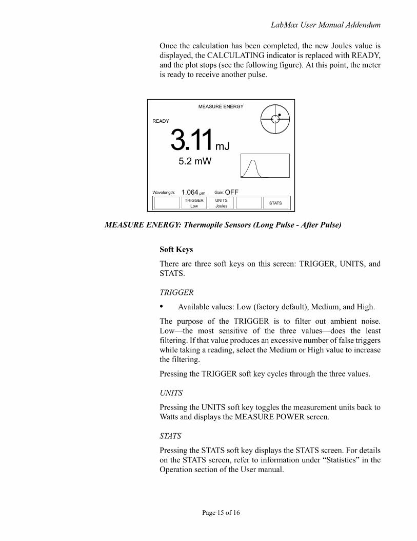
Once the calculation has been completed, the new Joules value isdisplayed, the CALCULATING indicator is replaced with READY,and the plot stops (see the following figure). At this point, the meteris ready to receive another pulse.
Soft Keys
There are three soft keys on this screen: TRIGGER, UNITS, andSTATS.
TRIGGER
• Available values: Low (factory default), Medium, and High.
The purpose of the TRIGGER is to filter out ambient noise.Low—the most sensitive of the three values—does the leastfiltering. If that value produces an excessive number of false triggerswhile taking a reading, select the Medium or High value to increasethe filtering.
Pressing the TRIGGER soft key cycles through the three values.
UNITS
Pressing the UNITS soft key toggles the measurement units back toWatts and displays the MEASURE POWER screen.
STATS
Pressing the STATS soft key displays the STATS screen. For detailson the STATS screen, refer to information under “Statistics” in theOperation section of the User manual.
MEASURE ENERGY: Thermopile Sensors (Long Pulse - After Pulse)
MEASURE ENERGY
UNITSJoules
STATS
Wavelength: Gain:1.064 µm OFF
READY
3.11 mJ5.2 mW
TRIGGERLow
Page 15 of 16

LabMax User Manual Addendum
Questions?
Call: (USA) 1.800.343.4912(Europe) +49-6071-968-0(International) 503.454.5700
or visit our website: www.Coherent.com
LabMaxTM User Manual Addendum© Coherent, Inc., 3/2009, (RoHS). Printed in the U.S.A.Part No. V006341
Page 16 of 16