Embed Size (px)
Citation preview

7/25/2019 Lab Manual v3
http://slidepdf.com/reader/full/lab-manual-v3 1/67
1 Department of Industrial Engineering
College of Engineering
King Saud University
IE 337 Industrial Automation Laboratory
Manual
Prof. Dr Ali M AL Samhan
Dr. Saber Darmoul
Eng. Ibraheem Ahmmed Alsharawy
Ver3.0, Jan 2014

7/25/2019 Lab Manual v3
http://slidepdf.com/reader/full/lab-manual-v3 2/67
2 Department of Industrial Engineering
College of Engineering
King Saud University
IE 337 Industrial Automation
Laboratory Manual
Prepared by
Prof. Dr. Ali M Alsamhan
(Prof. Department of Industrial Engineering KSU)
Dr. Saber Darmoul
(Assistant Prof. Department of Industrial Engineering KSU)
And
Engr. Ibraheem A. Alsharawy
(Researcher, Department of Industrial Engineering KSU)
Version 3.0 Jan. 2014
Supported by Department of Industrial Engineering, KSU
King Saud University
College of Engineering, Department of Industrial Engineering, P.O.Box 800, Riyadh 11421,
Kingdom of Saudi Arabia

7/25/2019 Lab Manual v3
http://slidepdf.com/reader/full/lab-manual-v3 3/67
3 Department of Industrial Engineering
College of Engineering
King Saud University
PrefaceEvery component of a product is supposed to perform satisfactorily on its job and
these components are engineered by considering a lot of aspects. Selection of the
right material with desired properties is the fundamental assessment. All of the
design efforts may failed down if the material does not have appropriate properties.
The knowledge of material regarding the manufacturing automation using
programmable logic controller, is important for industrial engineer. Factory
automation mainly covers; Machine level automation, Production line or work cell
automation, Shop floor automation, and Plant level automation. The present manual
focus on the 1st level of factory automation e.g. machine automation level. It
provides an introduction and application of programmable logic controller (PLC)
with illustrated example in automating the manufacturing processes. It also focuses
on some problems and applications of PLC in sequential and logic automations.
Furthermore, it introduces different types of logic sensors/actuators. Hence, this
manual is intended as a reference manual on Manufacturing Automation using PLCs,
for both undergraduate engineering students as well as practicing engineers.
Unit 1 covers theory and background on PLC, RLL programing basics, electric
sensor/actuators and pneumatic logic networks. The total integrated automation
software is introduced in Unit 2 and covers two experiments. Pneumatic network
design given in experiment 3. Connecting electric sensor to PLC input ports and also
electric switching elements are demonstrated in experiment 4. Design RLL and
programming using CASCADE method demonstrated in experiment 5. Special
functions like timer, counter analog input/output are given and illustrated using
experiment 6. Details of these problems are given and demonstrated in text book 1.
Writers;Industrial Engineering Department, KSU
1 Prof Dr Ali M AL Samhan, Prof Dr S.M. Darwish “Manufacturing Automation Using
PLCs, Supported by Research Center, College of Engineering Project No. 16/424, Ver
3.0 (Feb 2007)

7/25/2019 Lab Manual v3
http://slidepdf.com/reader/full/lab-manual-v3 4/67
4 Department of Industrial Engineering
College of Engineering
King Saud University
Table of Contents1. Unit 1: Theory and background ............................................................................................. 11
1.1 PLC and Relay Ladder Logic (RLL) .................................................................................. 11
1.1.1 The functions of these modules are given as follows: .......................................... 11
1.1.2 PLC Operation using scanning technique .............................................................. 14
1.1.3 Understanding Relay Ladder Diagram (RLL) .......................................................... 15
1.1.4 Basic Instructions of RLL, see Fig 1.9 ..................................................................... 17
1.1.5 Integrated automation system .............................................................................. 19
1.2 Electric logic sensors and actuators .............................................................................. 21
1.2.1 Electric sensors and actuators ............................................................................... 21
1.2.2 Electric Logic Sensor types .................................................................................... 21
1.2.3 Electric logic actuators........................................................................................... 25
1.2.4 Sensor wiring circuit .............................................................................................. 27
1.3 Pneumatic logic sensors and actuators ......................................................................... 29
1.3.1 Pneumatic and electric control systems ................................................................ 29
1.3.2 Pneumatic actuators.............................................................................................. 29
1.3.3 Pneumatic logic sensor and valves ........................................................................ 31
2. Unit 2: Total Integrated Automation TIA portal V12 software basics ................................... 36
2.1 The S7-300 PLC training Unit at Industrial Engineering Automation laboratory .......... 36
2.2 Task 1: Open existing project on TIA V12 portal (Experiment 1). ................................. 42
2.2.1 Objectives .............................................................................................................. 42
2.2.2 Outcomes of Laboratory Exercise ......................................................................... 42
2.2.3 Experimental Procedure : ..................................................................................... 43
2.3 Task 2: Open new project on TIA V12 portal (Experiment 2). ....................................... 48
2.3.1 Objectives .............................................................................................................. 48
2.3.2 Outcomes of Laboratory Exercise ......................................................................... 48
2.3.3 Requirement .......................................................................................................... 48

7/25/2019 Lab Manual v3
http://slidepdf.com/reader/full/lab-manual-v3 5/67
5 Department of Industrial Engineering
College of Engineering
King Saud University
2.4 Pneumatic networks (Experiment 3). ............................................................................ 55
2.4.1 Objectives .............................................................................................................. 55
2.4.2 Outcomes of Laboratory Exercise ......................................................................... 55
2.4.3 Requirements ........................................................................................................ 55
2.5 Electric logic sensor and actuators and wiring them to PLC (Experiment 4) ................ 58
2.5.1 Experimental objectives ........................................................................................ 58
2.5.2 Outcomes of Laboratory Exercise ......................................................................... 58
2.5.3 Requirements ........................................................................................................ 58
2.6 PLC, RLL programming using CASCADE method (Experiment 5) ................................... 61
2.6.1 Experimental objectives ........................................................................................ 61
2.6.2 Outcomes of Laboratory Exercise ......................................................................... 61
2.6.3 Requirements ........................................................................................................ 61
2.7 PLC timer, counter, registers and analog input/output functions (Experiment 6). ...... 64
2.7.1 Experimental objectives ........................................................................................ 64
2.7.2 Outcomes of Laboratory Exercise ......................................................................... 64
2.7.3 Requirements ........................................................................................................ 64

7/25/2019 Lab Manual v3
http://slidepdf.com/reader/full/lab-manual-v3 6/67
6 Department of Industrial Engineering
College of Engineering
King Saud University
List of Figures
FIGURE 1.1 INTERNAL STRUCTURE OF A PLC. .................................................................................... 11
FIGURE 1.2 PLC STRUCTURE, USER COMMUNICATION AND INTERFACES MODULES
INTERCONNECTIONS. ........................................................................................................................... 13
FIGURE 1.3 LAYOUT OF PLC SCANNING TECHNIQUE ...................................................................... 14
FIGURE 1.4 SIMPLE CONTROL CIRCUIT OF A BELL ......................................................................... 15
FIGURE 1.5 A TYPICAL INDUSTRIAL RELAY. ...................................................................................... 15
FIGURE 1.6 CONTACT RELAY SYMBOL. ............................................................................................... 16
FIGURE 1.7 OUTPUT RELAY SYMBOL. .................................................................................................. 16
FIGURE 1.8 RLL FOR BELL CONTROL CIRCUIT. .................................................................................. 16
FIGURE 1.9 MAIN INSTRUCTIONS IN RLL. ............................................................................................ 17
FIGURE 1.10 CONTROL AND RLL FOR AND BOOLEAN OPERATION. ............................................. 17
FIGURE 1.11 AMENDED RLL USING NORMALLY CLOSED SWITCH FOR SWITCH SW2. ............ 17
FIGURE 1.12 PROGRAMMING LANGUAGE FOR PLC FOR AND/OR GATES. .................................. 18 FIGURE 1.13 PLC PROGRAMMING TECHNIQUE USING PC COMPUTER THROUGH SERIAL
PORT. .................................................................................................................................................. 18
FIGURE 1.14 SIMATIC AND TOTALLY INTEGRATED AUTOMATION SYSTEM IN SIEMENS. .... 19
FIGURE 1.15 SIMATIC S7-300 GENERAL LAYOUT............................................................................... 20
FIGURE 1.16 GENERAL LAYOUT AND MODULES OF THE SIMATIC S7-300 SYSTEM. ................ 20
FIGURE 1.18 TYPES OF USER INTERFACE CONTACT ELECTRIC SWITCHES. .............................. 22
FIGURE 1.18 TYPES OF MACHINE LIMIT SWITCHES. ......................................................................... 22
FIGURE 1.19 REED MAGNETIC SWITCH OPERATION. ....................................................................... 22
FIGURE 1.20 TYPE OF INDUCTIVE AND CAPACITIVE PROXIMITY LOGIC SENSORS. ................ 23
FIGURE 1.21 OPTICAL LOGIC DETECTORS (THREE TYPES). ............................................................ 24
FIGURE 1.22 DIFFERENT TYPES OF SOLENOID LOGIC ACTUATORS. ............................................. 25
FIGURE 1.23 STRUCTURE OF ELECTROMECHANICAL RELAY, RELAY LADDER NOTATION,
BLOCK DIAGRAM OF MAIN INTERNAL STRUCTURE. ............................................................ 26
FIGURE 1.24 SOLID STATE RELAYS. ...................................................................................................... 26
FIGURE 1.25 TYPES OF WIRE SENSORS, TWO-WIRED LOAD-POWERED SENSOR, AND THREE-
WIRED LINE-POWERED SENSORS. .............................................................................................. 27
FIGURE 1.26 TRANSISTOR OUTPUT, CURRENT SINK TYPE. ............................................................ 28
FIGURE 1.27 TRANSISTOR OUTPUT CIRCUIT (CURRENT SOURCE). .............................................. 28
FIGURE 1.28 A DOUBLE ACTING PNEUMATIC MOTOR ..................................................................... 29
FIGURE 1.30 DOUBLE ACTING PNEUMATIC CYLINDER (LINEAR DISPLACEMENT ACTUATOR,
WITH DOUBLE ACTUATION PORTS) ........................................................................................... 30
FIGURE 1.30 SINGLE ACTING PNEUMATIC CYLINDER (LINEAR DISPLACEMENT ACTUATOR,
WITH SINGLE ACTUATION PORT) ............................................................................................... 30
FIGURE 1.31 NORMALLY CLOSED LIMIT VALVE STRUCTURE (ISI-ANSI SYMBOL) AND
CORRESPONDING ELECTRO-MECHANICAL SWITCH SYMBOL. .......................................... 31

7/25/2019 Lab Manual v3
http://slidepdf.com/reader/full/lab-manual-v3 7/67
7 Department of Industrial Engineering
College of Engineering
King Saud University
FIGURE 1.32 5-WAYS TWO POSITIONS DIRECTIONAL LIMIT VALVE, INTERNAL STRUCTURE,
ISI-ANSI VALVE NOTATION. ......................................................................................................... 32
FIGURE 1.33 5-WAYS TWO POSITIONS DIRECTIONAL LIMIT VALVE, INTERNAL STRUCTURE,
ISI-ANSI VALVE NOTATION. ......................................................................................................... 33
FIGURE 1.34 5-WAYS TWO POSITIONS SOLENOID VALVE. ............................................................. 33
FIGURE 1.35 SYMBOLS OF COMMON CONTROL SIGNALS FOR DIRECTIONAL VALVES .......... 34
FIGURE 1.36 ADDITIONAL PNEUMATIC SYMBOLS. .......................................................................... 34
FIGURE 2.1 S7-300 PLC TRAINING STATIONS AT INDUSTRIAL ENGINEERING DEPART
AUTOMATION LABORATORY. ..................................................................................................... 36
FIGURE 2.2 S7-300 TRAINING UNITS WITH PNEUMATIC AND ELECTRIC SWITCHING
ELEMENTS/ACTUATORS. .............................................................................................................. 37
FIGURE 2.3 GENERAL LAYOUT OF S7-300 PLC WITH ITS MODULES ............................................. 38
FIGURE 2.4 THE PNEUMATIC AND ELECTRIC SWITCHING ELEMENTS/ACTUATORS. .............. 39
FIGURE 2.5 HUMAN-MACHINE INTERFACE HMI) UNIT, PNEUMATIC SIMPLE NETWORK
SIMULATE R/S MEMORY UNITS ................................................................................................... 40
FIGURE 2.6 PC COMPUTER PROGRAMMING MEDIA FOR INSTALLED WITH SIMATIC S7
SOFTWARE V12.0 ............................................................................................................................. 41
FIGURE 2.8 EXPERIMENT 1.1. ...................................................................................................................... 43
FIGURE 2.8 EXPERIMENT 1.2. ....................................................................................................................... 43
FIGURE 2.10 EXPERIMENT 1.3 ...................................................................................................................... 44
FIGURE 2.10 EXPERIMENT 1.4 ..................................................................................................................... 44
FIGURE 2.13 EXPERIMENT 1.5 ...................................................................................................................... 45
FIGURE 2.13 EXPERIMENT 1.6 ...................................................................................................................... 45
FIGURE 2.13 EXPERIMENT 1.7 ...................................................................................................................... 45
FIGURE 2.14 EXPERIMENT 1.8 ..................................................................................................................... 46
FIGURE 2.15 CREATING NEW PROJECT: ................................................................................................ 49
FIGURE 2.16 CONFIGURING NEW DEVICE (1), ..................................................................................... 49
FIGURE 2.17 CONFIGURING NEW DEVICE (2), ..................................................................................... 49
FIGURE 2.18 CONFIGURING NEW DEVICE (3), ..................................................................................... 50
FIGURE 2.19 CONFIGURING NEW DEVICE (4), ..................................................................................... 50
FIGURE 2.20 CONFIGURING NEW DEVICE (5), ..................................................................................... 50
FIGURE 2.21 LOADING PROJECT (1), ....................................................................................................... 51
FIGURE 2.22 LOADING PROJECT (2), ....................................................................................................... 51
FIGURE 2.23 LOADING PROJECT (3), ....................................................................................................... 51
FIGURE 2.24 DEVELOP FIRST LAD NETWORK IN MAIN BLOCK OB1 (1), ....................................... 52 FIGURE 2.25 DEVELOP FIRST LAD NETWORK IN MAIN BLOCK OB1 (2), ....................................... 52
FIGURE 2.26 .................................................................................................................................................. 61
FIGURE 2.27 TIMER FUNCTIONS SYMBOLS ................................................................................................. 65

7/25/2019 Lab Manual v3
http://slidepdf.com/reader/full/lab-manual-v3 8/67
8 Department of Industrial Engineering
College of Engineering
King Saud University
List of Tables
TABLE 1.1: COMMON RATINGS FOR DISCRETE I/O INTERFACE MODULES. ................................................. 13
TABLE 2.1: COMPLETE THE FOLLOWING TASKS AND OBTAIN LAB SUPERVISOR
SIGNATURE FOR EACH .................................................................................................................. 53
TABLE 2.2: COMPLETE THE FOLLOWING TASKS AND OBTAIN LAB SUPERVISOR SIGNATURE
FOR EACH .......................................................................................................................................... 56
TABLE 2.3: COMPLETE THE FOLLOWING TASKS AND OBTAIN LAB SUPERVISOR SIGNATURE
FOR EACH .......................................................................................................................................... 59
TABLE 2.4: COMPLETE THE FOLLOWING TASKS AND OBTAIN LAB SUPERVISOR SIGNATURE
FOR EACH .......................................................................................................................................... 62
TABLE 2.5: COMPLETE THE FOLLOWING TASKS AND OBTAIN LAB SUPERVISOR SIGNATURE
FOR EACH .......................................................................................................................................... 67

7/25/2019 Lab Manual v3
http://slidepdf.com/reader/full/lab-manual-v3 9/67
9 Department of Industrial Engineering
College of Engineering
King Saud University
Theory and Background On Industrial Automation
UNIT 1

7/25/2019 Lab Manual v3
http://slidepdf.com/reader/full/lab-manual-v3 10/67
10 Department of Industrial Engineering
College of Engineering
King Saud University
Theory and Background:
PLC, Relay Ladder Logic RLL
electric and pneumatic logi
sensor/actuators.
AbstractThis unit is dedicated to the introduction to manufacturing automation us
programmable logic controller (PLC). It provides on basic hardware and softw
components of PLC, and provide outlook on the available PLC training station
also, illustrates the layout of main components of PLC which cover, power sup
unit, CPU unit, discrete input and outputs modules as well as analog continu
input/output modules. Also, provide details on the programming ports, mainly se
ports and also communication ports, with Human-Machine-Interface (HMI) unit.
There are many type of PLC manufactures for different industries. Some of th
general purpose type and some of them applied for specific automation applicati
In this lab. Mainly Siemens S7-300 type introduced and mounted on the train
station with TIA Ver 12.0 software as programming media. In the same PLC train
station, there are also different pneumatic actuators and solenoid valve switch
elements as well as different electromechanical relay as switching elements and u
push-button switches to be used with the experiments.

7/25/2019 Lab Manual v3
http://slidepdf.com/reader/full/lab-manual-v3 11/67
11 Department of Industrial Engineering
College of Engineering
King Saud University
1. Unit 1: Theory and background1.1 PLC and Relay Ladder Logic (RLL)
PLC stands for programmable logic controller. PLCs are electronic control devices thatare used in variety of industries, ranging from manufacturing plants to processing plants.
A PLC is a device that was invented to replace the necessary sequential relay circuits formachine control and to replace analog controller. The PLC works by looking at its inputs
(both logic and continues types) and depending upon their state, turning on/off itsoutputs. Examples: PLCs used in automotive assembly plants, automotive parts
manufacturing plants, mineral processing plants, semi-conductor manufacturing plants,
steel mills ….etc. The user enters a program, usually via software, that gives the desired
results.
The PLC has three components;
a) Central Processing Unit CPU,
b) Inputs,
c) Outputs.
We could consider the PLC to be a box of hundreds of separate relays, counters, timers
and data storage locations. Do these counters, timers, etc. really exist? No, they
"physically" don't exist but rather they are simulated and can be considered softwarecounters, timers, etc. The internal relays are simulated through bit locations in registers,
as shown in Fig. 1.1.
1.1.1 The functions of these modules are given as follows:
INPUT RELAYS-(contacts): These are connected to the outside world. They
physically exist and receive signals from switches, sensors, etc. Typically they are notrelays but rather they are transistors. These inputs are called discrete or logic inputs.
INTERNAL UTILITY RELAYS-(contacts): These relays do not receive signalsfrom the outside world nor do they physically exist. They are simulated relays and are
what enables a PLC to eliminate external relays. There are also some special relays
that are dedicated to performing only one task. Some are always on while some arealways off. Some are on only once during power-on and are typically used for
initializing data that was stored.
Figure 1.1 internal structure of a PLC.
Analog
Input
Analog
Output
Networking
module
Modem

7/25/2019 Lab Manual v3
http://slidepdf.com/reader/full/lab-manual-v3 12/67
12 Department of Industrial Engineering
College of Engineering
King Saud University
COUNTERS: These again do not physically exist. They are simulated countersand they can be programmed to count pulses. Typically these counters can count up,
down or both up and down. Since they are simulated they are limited in their countingspeed. Some manufacturers also include high-speed counters that are hardware based. We
can think of these as physically existing. Most of the time these counters can count up,down or up/down.
TIMERS: These also do not physically exist. They come in many varieties andincrements. The most common type is an on-delay type. Others include off-delay and
both retentive and non-retentive types. Increments vary from 1ms through 1s.
OUTPUT RELAYS-(coils):These are connected to the outside world. They physically exist and send on/off signals to solenoids, lights, etc. They can be transistors,
relays, or triacs depending upon the model chosen.
DATA STORAGE: Typically there are registers assigned to simply store the data.They are usually used as temporary storage for math or data manipulation. They can also
typically be used to store data when power is removed from the PLC . Upon power-onthey will still have the same contents as before when power has been removed.
ANALOG MODELS: This covers analog inputs and outputs. The analog modelscover reading analog signals from sensor, provides analog signal such as thermocouples,
strain gauges, thermistor, pressure sensor….etc. The analog output signals can be used tocommand external controller e.g. servomotors amplifier, solenoid amplifier …etc.
USER INTERFACE INPUT: Which contains extra push-bottoms that can be
configured by the user to set/reset logic output devices e.g. relays outputs, or can be usedas storage of messages that can be displayed on liquid crystal display. Furthermore, some
of these interfaces have led which can be configured by the user.
NETWORKING MODULES: Larger PLC s could have serial port that can be usedfor networking a multiple of PLCs that are to be programmed from one main computer or
sending/receiving data between PLC networks. Furthermore, some of the PLCs are
equipped with remote control module (modem) to program the PLC from long distance
computer.
The CPU of the PLC contains a microprocessor, which means that a PLC is basically a
specialized computer that has been designed to control the operation of machines and
processes within the harsh environment of the plant.
The language used to program the PLC to perform the logic required to connect thefielded input to its outputs is called Relay Ladder Logic (RLL). The RLL language is
programmed by means of special software using personal computer (connected to the
PLC using serial port) or hand-held programmer which has led or liquid-crystal display,
see Fig. 1.2.

7/25/2019 Lab Manual v3
http://slidepdf.com/reader/full/lab-manual-v3 13/67
13 Department of Industrial Engineering
College of Engineering
King Saud University
RAM and EPROM memory are used to store the program instructions in the PLC . Thecomputer or hand-held programmer can be used to load and save the RLL programs into
the PLC .
The physical input and output modules can be discrete or analog I/O modules and can be
selected and specified when purchasing the PLC , and depend on the number of therequired I/O lines.
The discrete I/O modules connects field inputs devices of the ON/OFF nature like limit
switches, push button switches, solenoids, solenoid valve or electro-mechanical relay
..etc. Each discrete I/O module supply voltage source. Since these voltages can be of
different magnitude or types, I/O modules are available at various AC & DC voltagesratings as shown in Table 1.1. Furthermore, the inputs and outputs are connected to
LED’s to indicate the operation of the I/O module
Table 1.1: common ratings for discrete I/O interface modules.
Interface input module Interface output modules
24 V AC/DC 12-48 V AC
48 V AC/DC 120 V AC
230 V AC/DC 230 V DC
5 V (TTL) V DC (TTL)
CPU & Memory
Input
Module
(logic or
Output
module
(logic
Power Supply
M
S
Figure 1.2 PLC structure, user communication and interfaces modules
Hand-held programmer or PC communication

7/25/2019 Lab Manual v3
http://slidepdf.com/reader/full/lab-manual-v3 14/67
14 Department of Industrial Engineering
College of Engineering
King Saud University
1.1.2 PLC Operation using scanning technique
A PLC works by continually scanning a program. It can be think of this scan cycle as
consisting of 3 important steps, see Fig. 1.3. There are typically more than three steps butit is possible to focus on the important parts and ignore the others. Typically the others
are checking the system and updating the current internal counter and timer values.
Step 1: CHECK INPUT STATUS:
First the PLC takes a look at each input to determine if it is on or off. In other words, isthe sensor connected to the first input on? How about the second input? How about the
third. It records this data into its memory to be used during the next step.
Step 2: EXECUTE PROGRAM:
Next the PLC executes your program one instruction at a time. Maybe the program said
that if the first input was on then it should turn on the first output. Since it already knows
which inputs are on/off from the previous step it, will be able to decide whether the firstoutput should be turned on based on the state of the first input. It will store the execution
results for use later during the next step.
Step 3: UPDATE OUTPUT STATUS:
Finally the PLC updates the status of the outputs. It updates the outputs based on whichinputs were on during the first step and the results of executing the PLC program during
the second step. Based on the example in step 2, it would now turn on the first output
because the first input was on and the program said to turn on the first output when thiscondition is true.
After the third step the PLC goes back to step one and repeats the steps continuously.
One scan time is defined as the time it takes to execute the 3 steps listed above.
Figure 1.3 Layout of PLC
scanning technique

7/25/2019 Lab Manual v3
http://slidepdf.com/reader/full/lab-manual-v3 15/67
15 Department of Industrial Engineering
College of Engineering
King Saud University
1.1.3 Understanding Relay Ladder Diagram (RLL)
To understand the programming of PLC relay ladder diagram, let us start with simple
case of relay control system, see Fig 1.4. It can be think of a relay as an electromagneticswitch. Apply a voltage to the coil results in a magnetic field is generated. This magnetic
field sucks the contacts of the relay in, causing them to make a connection. These
contacts can be considered to be a switch. They allow current to flow between 2 pointsthereby closing the circuit.
Let's consider the following example. Here a simply turn on a bell whenever a switch isclosed, as shown in Fig. 1.4. In real-world there are 3 parts; a switch, a relay and a bell.
Whenever the switch closes apply a current to the bell causing it to sound. The bottom
circuit indicates the DC control circuit. The top circuit indicates the AC control circuit.Here a DC relay is used to control an AC circuit. That’s the benefit of using relay. When
the switch is open no current can flow through the coil of the relay. As soon as the switch
is closed, however, current runs through the coil cause a magnetic field to build up. Thismagnetic field causes the contacts of the relay to close. Now AC current flows throughthe bell. Fig. 1.5 shows a typical industrial relay which consist of the main components,
contact switch-spring system, coil and mounting base with different connection pins.
Next, think like the relay control system is replaced with PLC control system using relay
ladder logic. After seeing a few of these it will become obvious why it’s called a ladder
diagram. However, be noted unfortunately, a PLC doesn't understand a schematicdiagram. It only recognizes code. Fortunately most PLCs have software, which convert
ladder diagrams into code. This shields us from actually learning the PLC's code.
Figure 1.4 Simple control circuit of a bell
Power circuit
Figure 1.5 A typical industrial relay.
7/25/2019 Lab Manual v3
http://slidepdf.com/reader/full/lab-manual-v3 16/67
16 Department of Industrial Engineering
College of Engineering
King Saud University
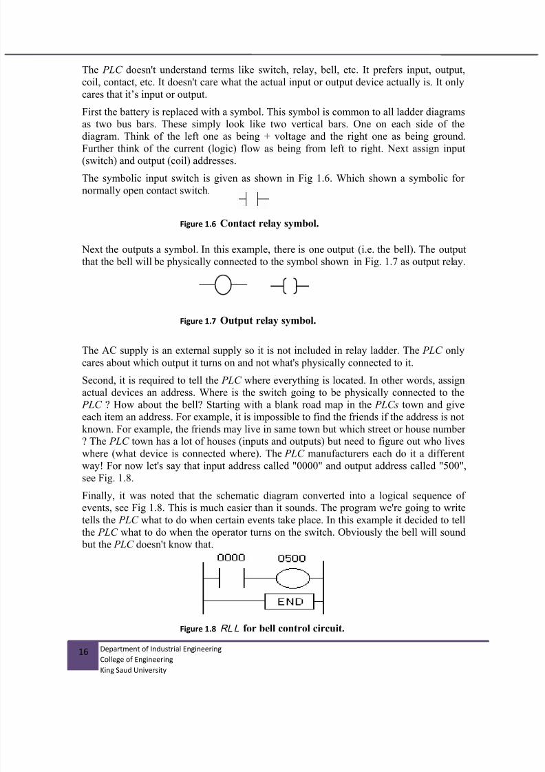
The PLC doesn't understand terms like switch, relay, bell, etc. It prefers input, output,
coil, contact, etc. It doesn't care what the actual input or output device actually is. It only
cares that it’s input or output.
First the battery is replaced with a symbol. This symbol is common to all ladder diagramsas two bus bars. These simply look like two vertical bars. One on each side of the
diagram. Think of the left one as being + voltage and the right one as being ground.Further think of the current (logic) flow as being from left to right. Next assign input(switch) and output (coil) addresses.
The symbolic input switch is given as shown in Fig 1.6. Which shown a symbolic for
normally open contact switch.
Next the outputs a symbol. In this example, there is one output (i.e. the bell). The output
that the bell will be physically connected to the symbol shown in Fig. 1.7 as output relay.
The AC supply is an external supply so it is not included in relay ladder. The PLC only
cares about which output it turns on and not what's physically connected to it.
Second, it is required to tell the PLC where everything is located. In other words, assign
actual devices an address. Where is the switch going to be physically connected to the
PLC ? How about the bell? Starting with a blank road map in the PLCs town and giveeach item an address. For example, it is impossible to find the friends if the address is not
known. For example, the friends may live in same town but which street or house number? The PLC town has a lot of houses (inputs and outputs) but need to figure out who lives
where (what device is connected where). The PLC manufacturers each do it a different
way! For now let's say that input address called "0000" and output address called "500",
see Fig. 1.8.
Finally, it was noted that the schematic diagram converted into a logical sequence ofevents, see Fig 1.8. This is much easier than it sounds. The program we're going to write
tells the PLC what to do when certain events take place. In this example it decided to tell
the PLC what to do when the operator turns on the switch. Obviously the bell will sound
but the PLC doesn't know that.
Figure 1.6 Contact relay symbol.
Figure 1.7 Output relay symbol.
Figure 1.8 RLL for bell control circuit.

7/25/2019 Lab Manual v3
http://slidepdf.com/reader/full/lab-manual-v3 17/67
17 Department of Industrial Engineering
College of Engineering
King Saud University
The Fig. 1.8shows the final converted diagram ( RLL) for bell control system. Notice that
we eliminated the real world relay from needing a symbol. Also noted, the END
statement at the end of the program.
1.1.4 Basic Instructions of RLL, see Fig 1.9
Example 1:
Draw ladder logic for the control circuit shown in Fig. 1.10:
The Boolean AND logic equation for this control circuit: Coil = SW1 . SW2
Example 2:
Redraw the relay ladder logic of Example 1, using normally closed switch for SW2 ?
The amended RLL is shown in Fig. 1.10, to Fig 1.11:
The main language used to program the PLC to perform the logic required and to connect
the field input to its outputs is called Relay Ladder Logic (RLL or LAD). Other
languages like FBD and STL also available for PLC programming (not considered in
1.1.1.1.1 Main input
instructions
Normally open contact :
Normally closed contact :
1.1.1.1.2 Main output
instructions
Normally open relayNormally closed relay
Figure 1.9 Main instructions in RLL .
Figure 1.10 Control and RLL for AND Boolean
Figure 1.11 Amended RLL using normally closed switch for switch SW2.

7/25/2019 Lab Manual v3
http://slidepdf.com/reader/full/lab-manual-v3 18/67
18 Department of Industrial Engineering
College of Engineering
King Saud University
current project). All languages can be used in same program. For example, it is possible
to program PLC with STL method through two lines, same program need three pages in
LAD language. Fig. 1.12, shows three types of programming languages for AND/ORgates. As illustrated in there are four discrete inputs switches (S1, S2, S3 and S4) and
three discrete outputs (L1, L2 and L3). Each input and output has discrete input address
shown of I0.0, I0.1, …I0.3 and four discrete output of Q8.0 … Q8.2 .
The RLL (LAD) language is programmed by means of special software using personalcomputer (connected to the PLC using serial port) or hand-held programmer which has
led or liquid-crystal display and keyboard, see Fig 1.13.
Figure 1.12 Programming language for PLC for AND/OR gates.
Figure 1.13 PLC Programming technique using PC computer through serial port.

7/25/2019 Lab Manual v3
http://slidepdf.com/reader/full/lab-manual-v3 19/67
19 Department of Industrial Engineering
College of Engineering
King Saud University
1.1.5 Integrated automation system
Production processes are no longer seen as individual processes, but rather as integral
components of an entire production process. The total integrated automation environment
is today achieved with the help of:
One common software environment that integrates all components and tasks intoone uniform easy to use system.
A common data management (central database).
A common communication between all participating automation components.
Siemens one of the leaders in the field of total integrated automation system for theirautomation system, see Fig 1.14. Simatic S7 is developed by Siemens for solving the
totally integrated automation system. This platform software coves barriers between
computer, PLC, and process control plus operator interface and monitoring system for
controller process.
Simatic S7 is a family of PLC and cover, micro-plc (S7-200) performance range, (S7-
300) lower/middle range and (S7-400) middle-upper performance range.
Simatic C7 is a complete system combine of the PLC (S7-300) with an operator panel
interface (HMI) and process monitoring system.
WinAC is a PC-based solution. It is used when various automation tasks (control,visualization, data processing) are to be solved with PC.
Figure 1.14 Simatic and totally
integrated automation system in
Siemens.

7/25/2019 Lab Manual v3
http://slidepdf.com/reader/full/lab-manual-v3 20/67
20 Department of Industrial Engineering
College of Engineering
King Saud University
In this laboratory work we will focus on the S7-300 PLC, see Fig 1.15 family which also
available in Industrial Engineering Automation Laboratory.
The general layout of S7-300 PLC with its modules is shown in Fig 1.16. As illustrated in Fig.,the first slot of the system is the power supply (PS) mounted to top-left side of the figure. Next
slot from the left side is the CPU. Next, IM model (multi-tier) which is option. Next, discrete
input and outputs (SM-DI, SM-DO). Next, the analog input/output models (SM-AI, SM-AO),followed by the FM model (counter, positioning, closed loop control modules), and finally, CP
module (point-to-point, profibus and industrial Ethernet) communication module.
Figure 1.15
Simatic S7-300 general
layout.
Figure 1.16 General layout and modules of the Simatic S7-300 system.

7/25/2019 Lab Manual v3
http://slidepdf.com/reader/full/lab-manual-v3 21/67
21 Department of Industrial Engineering
College of Engineering
King Saud University
1.2 Electric logic sensors and actuators
1.2.1 Electric sensors and actuators
Electric sensors and actuators can be classified as continuous and/or logic types. Electric
logic sensors can be used as standalone control system or can be connected to PLCdiscrete input to detect the state of the process as true or false (on or off). Similarlyelectric logic actuators can be used as standalone control system or can be driven by PLC
discrete outputs to activate or deactivate machine logic mechanical actuators.
On the other hand, continuous sensors are those, which generate a continuous signal
(voltage or current) that proportional with the actual physical variable. This signal has
either analog or digital values depend of the type of the sensor and can be fed very easilyto the PLC module to measure the physical variable. For example, a linear potentiometer
will generate analog output signal proportional to linear displacements. Continuous
actuator like DC servomotors can be driven using servo drive (or servo amplifier) that
commanded using analog control signal generated by the PLC ports.
1.2.2 Electric Logic Sensor types
The main function of using electric logic sensors detecting the present or absent of
objects. This achieved either with direct physical contact (e.g. contact switches), or by
moving the object nearby the sensor (e.g. proximity sensors), or by breaking a beam of
light between object and sensor (e.g. photoelectric sensors). Hence, the main categoriesof electric logic sensors are contact switches, proximity sensors and photoelectric
sensors.
Contact switches
Internally, contact switches consist of electric contacts driven by mechanical lever andspring. When applying a small force on this mechanical liver it will actuates the contact.Removing the force will return contact to its original position, by return spring.
Contact switches are available with either normally closed NC or normally opened NO
contacts. Micro limit switches can be found with small equipment, while heavy-duty limit
switches (more expensive) can be found with large equipment. Contact switches can beused as motion limit switches or as push bottoms switches and used as user-machine
interface switches, e.g. start/stop push button switches, see Fig 1.17 and 1.18.
Proximity reed sensorsA reed switch consist of two leaf springs (called reeds) sealed in small glass tube with
two free ends overlapping and almost touching. Reed switches are nearly similar toelectro-mechanical relays, except that the magnetic field is developed by permanent
magnet instead of electric coil. The permanent magnet is mounted on the moving part.
Fig. 1.19 shows how reed switch operates. As long as the permanent magnet moved
toward the reed switch and get closer the switch will close or open the contacts,depending on the contact type NO or NC contact.

7/25/2019 Lab Manual v3
http://slidepdf.com/reader/full/lab-manual-v3 22/67
22 Department of Industrial Engineering
College of Engineering
King Saud University
Figure 1.19 Reed magnetic switch operation.
Figure 1.18 Types of user interface contact electric switches.
Figure 1.18 Types of machine limit switches.

7/25/2019 Lab Manual v3
http://slidepdf.com/reader/full/lab-manual-v3 23/67
23 Department of Industrial Engineering
College of Engineering
King Saud University
Inductive proximity sensorsStrictly speaking, the reed switches and photoelectric sensors discussed so far, are all
proximity sensors. However, the term “proximity sensors” generally refers to devices
based on inductive, capacitive or magnetic effects, with some electronic circuits, that candetect the presence of an object. These proximity sensors are usually packed in one of
two ways, as shown in Fig. 3.4. Some come in standard limit-switch enclosures, whichfacilitate interchangeability and maintenance and other called threaded-barrel type. Mostinductive proximity sensors operate by generating high-frequency electromagnetic fields
that induces eddy current in the metal target. The sensor inductance is part of an oscillator
circuit. When the target (which must be a conducting material) near the sensor the
oscillations are damped. This resulting in change in oscillator current which actuates asolid-state switch. Sensing distance from 2 to 30 mm, also depends on the target size,
thickness, material, and temperature. The material of the object must be ferrous material.
Proximity capacitive sensor
These contain a damped RC oscillator. When a target, which need not be of
conducting materials (such as liquid, water, oil, powder, wood, plastic …etc), is brought
within operating range of the sensor, the resulting change in capacitance causes thecircuit to actuate a solid-state switch. The maximum sensing distances range from 5 to 40
mm, depend on the sensor design and target material. General layout of these sensors are
also shown in Fig. 1.20.
The main advantage of the capacitive proximity sensors is that they are not limited tometallic targets. Thus, they can be used to detect the level of a liquid or solid material in
the vessel. Also they can detect objects inside sealed containers. However, theirswitching accuracy is affected by humidity and temperature. They have low responses for
detecting very high speed moving objects when compared to the inductive sensors.
Figure 1.20 Type of inductive and capacitive proximity logic sensors.

7/25/2019 Lab Manual v3
http://slidepdf.com/reader/full/lab-manual-v3 24/67
24 Department of Industrial Engineering
College of Engineering
King Saud University
Photoelectric sensors
Photoelectric sensors consist basically of a source emitting a light beam and a light-
sensing detector receiving the beam. The object to be sensed interrupts or reflects the
beam, thereby making its presence known without physical contact between sensors and
object.
Three types are common:
a) In the operation mode of the through-beam photoelectric sensor, the emitter anddetector are mounted in separate housings which is aligned carefully so as to face
each other exactly. As the target to be detected approaches, it breaks the beam. In this
type of operation the sensor can work for larger length up to 100 m, provided the
beam is concentrated and the air is clean also the emitter and detector are accuratelyaligned. An interesting variation of the through-beam principle can be used as smoke
detector (such as in domestic fire alarm).
b) In the reflection operation mode of photoelectric sensor, the emitter and detector are
built into a single housing, which reduces wiring and mounting cost. The target,when it reaches the proper location, reflects the beam back into the detector. Sinceonly part of the emitter light returns to the detector, this mode is only suitable for
fairly small distances, where the air must be reasonably clean of contamination. The
method can be used for detecting the liquid level.
c) In the retroflection operation mode, a special reflector (typically a formed plastic
surface with small embedded spheres or pyramids) reflects the light beam back intothe detector, regardless of the angle of incidence, unless the target interrupts it. Here
also the emitter and detector are mounted on the same housing. This method can be
used to sense a distance up to 10 m in the absence of atmospheric contaminations.
Figure 1.21 Optical logic detectors (three types).

7/25/2019 Lab Manual v3
http://slidepdf.com/reader/full/lab-manual-v3 25/67
25 Department of Industrial Engineering
College of Engineering
King Saud University
1.2.3 Electric logic actuators
Displacement solenoids
Solenoids are electromechanical devices consisting of an electromagnetic coil and
plunger (also called armature), as illustrated in Fig 1.22. When current is sent through the
coil, the resulting magnetic field draws the sleeve within the coil; this will convert theelectric energy to mechanical linear displacement (linear or rotary displacements).
Relay switching elementThere are three basic relay types: Electromechanical relay, reed relay, and solid-staterelays. Relays are used for two purpose as logic switching elements (i.e. control relay), or
as current or voltage amplifiers (i.e. power relays).
a) Electromechanical relays
Electromechanical relays (EMRs) consist of an electromagnetic coil and core designed to
pull in an armature against a spring (i.e. basically a solenoid), and a number of electricalcontacts. The armature is connected to the contacts so that all switches are simultaneously
in operation when the coil is energized. Fig. 1.23 shows general structure of EMR.
Relay contacts are either normally open (NO) or normally closed (NC). The term
“normally” refers to the state in which the coil is not energized. Relays can have manyindependent contacts, some of these are NO and other NC and each contact can be used
on the same circuit.
Figure 1.22 Different types of solenoid logic
actuators.

7/25/2019 Lab Manual v3
http://slidepdf.com/reader/full/lab-manual-v3 26/67
26 Department of Industrial Engineering
College of Engineering
King Saud University
b) Reed Relay
Reed relays are close to the reed switches. However, while reed switches are actuated bya moving permanent magnet, reed relays contain several reed capsules actuated by one
stationary electromagnet. Thus the armature and mechanical like is eliminated in EMR
and seal reed tubes or capsules replace the contacts. Life is more that EMR, nearly 108
operations, contact rating up to 1 Amp and operating time up to 0.5 msec.
c) Solid state relay
Solid-state relays (SSRs) are invariably compared with EMR and reed relays. Most SSR
switches one circuit, equivalent to SPST relay, see Fig. 1.24. It is not suitable switching
logic operations; used as output elements which interfaces the logic gates to the outsideload.
Figure 1.23 Structure of electromechanical relay, Relay ladder notation,
block dia ram of main internal structure.
Figure 1.24 Solid state relays.

7/25/2019 Lab Manual v3
http://slidepdf.com/reader/full/lab-manual-v3 27/67
27 Department of Industrial Engineering
College of Engineering
King Saud University
1.2.4 Sensor wiring circuit
When detecting the logic state of a process, the sensor must signal this state to the PLC
through switching either voltage or current from on to off or from off to on. The outputfrom the sensor will be an input to the PLC.
Sensor interface to other control circuits (sensor output circuit) are different. The controlvoltage type, whether AC,DC or AC/DC can be grouped to be as Load-Power Sensor or
Line-Power Sensor, see Fig 1.25
Load-power devices are similar to limit switches. They are connected in series with the
controlled load. These devices have two connection points to the circuit and are often
referred to as 2-wire switches, see Fig 3.8a. In another hand, Line-powered switchesderive their power from the line and not through load, see Fig.3.8b. They have three
connection points to the circuit, and are often referred to as 3-wire switches. The
operating current pulls from the line and is called the Burden Current. This is typically
20mA (e.g. transistor sensor output)
There are mainly three output types: Relay, Traic and Transistor outputs.
Relay output: A relay is a mechanical device that can handle load current at higher
voltage. This allows the sensor to directly interface with motor, solenoids and other
inductive load. They can be used to switch either AC or DC voltage.
A Triac Output: A triac is a solid-state device designed to control AC current. A triacswitch turn on in less than microsecond when its gate (control gate) is energized. As long
as triac is used within its rated maximum current and voltage, triac has infinite life.
A Transistor Output: It is also solid state device designed to control DC current. There
are mainly two types of circuits depending on the switching function:
Figure 1.25 Types of wire sensors, two-wired load-powered sensor, and
- -

7/25/2019 Lab Manual v3
http://slidepdf.com/reader/full/lab-manual-v3 28/67
28 Department of Industrial Engineering
College of Engineering
King Saud University
NPN (Current Sink) open collector; Here the output transistor is connected to the
negative DC. Current flows from the positive terminal through the load, to the sensor, to
the negative terminal. The sensor “sinks” the current from the load, as shown Fig.1.26.
PNP (Current Source); the sensor is connected to the positive DC and current flows
from the positive terminal through the sensor, to the load, to the negative terminal. The
sensor “sources” the current to the load, see Fig 1.27.
Figure 1.26 Transistor output, current sink type.
Figure 1.27 Transistor output circuit (Current Source).

7/25/2019 Lab Manual v3
http://slidepdf.com/reader/full/lab-manual-v3 29/67
29 Department of Industrial Engineering
College of Engineering
King Saud University
1.3 Pneumatic logic sensors and actuators
1.3.1 Pneumatic and electric control systems
Like electric control system, pneumatic control system can be used directly without PLC
controller to build control circuit actuating pneumatic assembly machine. There aresimilarity between electric control circuit and pneumatic control circuits. In electricsystem current and voltage are the main parameters determine electric machine power. In
another hand, flow and pressure are the corresponding parameters in pneumatic control
system that determines the machine power.
Pneumatic control system is frequently used in building automatic assembly machinesdue to low cost compare to hydraulic or electric systems. Also, high response time
compare to hydraulic.
Hydraulic system is commonly used for heavy duty and heavy load involved, e.g. heavy
transportation vehicles.
1.3.2 Pneumatic actuators
Like electric system, pneumatic actuators can provide either linear or angular
displacements. Pneumatic linear displacement achieved using pneumatic single and/or
double acting cylinders. While, angler displacement commonly achieved using singleand/or double acting air motors. Fig 1.28 – Fig 1.30 show double acting pneumatic
motor, pneumatic double acting cylinders and single acting cylinder respectively. Double
acting actuators, means the actuator can be activated for two directions e.g.forward/backward or clockwise/counterclockwise rotation.
Figure 1.28 A double acting
pneumatic motor

7/25/2019 Lab Manual v3
http://slidepdf.com/reader/full/lab-manual-v3 30/67
30 Department of Industrial Engineering
College of Engineering
King Saud University
It is worth noting, increase in pressure will produce high force in case of pneumaticcylinders, while increase the torque in case of pneumatic motor. In another hand, increase
pneumatic flow will increase cylinder linear speed, while increase the motor RPM in case
of pneumatic motor.
High pressurizes air usually obtained using main air compressor that produce pressure between 4 to10 bars. This pressure quite high in some applications, hence, pressure
regulator is required to reduce the pressure to the required level.
Figure 1.30 Double acting
pneumatic cylinder (linear
displacement actuator, with
double actuation ports)
Figure 1.30 Single acting
pneumatic cylinder (linear
displacement actuator, with
single actuation port)

7/25/2019 Lab Manual v3
http://slidepdf.com/reader/full/lab-manual-v3 31/67
31 Department of Industrial Engineering
College of Engineering
King Saud University
1.3.3 Pneumatic logic sensor and valves
The main structure of the limit valves, push button and emergency stop valves are same
like electric limit, push button and emergency switches. The main difference betweenthe pneumatic limit valves and the mechanical switches, in the latter, the actuating arm or
plunger shifts a so-called directional-control valve rather than electric contacts. Similarly
directional valves can be single pole-single through (SPST) (e.g. has one output eithernormally open (NO) or normally closed) or single pole-double through (SPDT)(e.g. has
double outputs one is normally open and another normally closed).
Single-pole-single through configuration used mainly to drive pneumatic actuator in one
direction (e.g. single acting cylinder or one direction pneumatic motor). In another hands,
single pole double through commonly used to drive pneumatic actuators in doubleopposite ways (e.g. double acting cylinder or two direction pneumatic motor). For
example, consider Fig. 1.31, which shows a so-called 3/2 limit valve (meaning 3
connections and 2 positions valve). The valve shown as normally closed, so that theoutlet line is exhausted to atmosphere when the valve is not actuated. When the valve is
actuated, the roller is depressed against the return spring at the bottom, so that the valveopens and passes supply pressure to the outlet line.
Fig 1.31 shows also ISO/ANSI symbol for 3/2 valve. The symbol consist of two squares,
which represent the two position valve, have internal and external notation. External
notation shown on the top of the square for the three ports. In top rectangular, the circlewith center dot notation represent the pressure air supply, while small triangle represent
the exhaust. The output is represented by simple small horizontal line in right direction as
shown in section view. The internal notations cover the arrow directions and T-notation.
Arrow show the flow direction (pressure flow from high to low level), while T-notation
represent that the valve is blocked at that port. Since, the external notation is shown onthe top rectangular, this represent the state of the valve without actuation, while thesecond rectangular represent the state of the valve after actuation. Furthermore, thecontrol signal that actuate the 3x2 valve shown in Fig 4.2 are roller plunger with spring
return. This type of limit valve called 3x2 limit valve with spring return (no mechanical
memory)
Figure 1.31 Normally closed limit valve structure (ISI-ANSI symbol)
and corresponding electro-mechanical switch symbol.

7/25/2019 Lab Manual v3
http://slidepdf.com/reader/full/lab-manual-v3 32/67
32 Department of Industrial Engineering
College of Engineering
King Saud University
Figure 1.32 5-ways two positions directional limit valve, internal
structure, ISI-ANSI valve notation.
Fig. 1.32 illustrates another pneumatic limit valve called 5/2 limit valve (meaning 5
connections and 2 positions valve), which has two independent outlet lines, one is
normally open and normally closed outputs. Such a valve is analogous to limitmechanical switch with changeover contacts (NO and NC contacts switch), single pole
double through (SPDT).
Most directional-control valves are of the spool and sleeve type. Fig. 1.33, shows a 5/2
spool valve (schematically). When the spool position or pilot line has been pressurized by p1 line. Flow line between A & D ports, and B & E posts are passed, while C is blocked.
If pilot line p2 is pressurized, the spool shifted to the lift with corresponding change in
flow paths as illustrated in Fig 4.4. Also, Fig. 4.4 shows also the ISO or ANSI standardsymbol of 5/2 way directional valve. This type of directional valve can be used as SET-
REST mechanical memory in pneumatic circuit.

7/25/2019 Lab Manual v3
http://slidepdf.com/reader/full/lab-manual-v3 33/67
33 Department of Industrial Engineering
College of Engineering
King Saud University
The main difference between the solenoid actuation directional control valve and pilot
control valve, is the way of displacement of the valve spool. Spool valve displacement is
carried out using two pressurized air p1 and p2 in case of the pilot control valve. While
solenoid and spring mechanisms are used to displace the spool valve in case of thesolenoid actuation directional valve (or simply solenoid directional valve) as shown in
Fig. 1.34. Similarly, solenoid actuation can also be used with 3/2 ways directional valve.
Different control singles can be used to actuate the directional valves, Fig 1.35 show
some of the methods used for different applications. Different pneumatic notations areshown in Fig 1.36.
Figure 1.33 5-ways two positions directional limit valve, internal
structure, ISI-ANSI valve notation.
Figure 1.34 5-ways two positions solenoid valve.

7/25/2019 Lab Manual v3
http://slidepdf.com/reader/full/lab-manual-v3 34/67
34 Department of Industrial Engineering
College of Engineering
King Saud University
Figure 1.35 Symbols of common control signals for directional valves
Figure 1.36 Additional pneumatic symbols.

7/25/2019 Lab Manual v3
http://slidepdf.com/reader/full/lab-manual-v3 35/67
35 Department of Industrial Engineering
College of Engineering
King Saud University
Total Integrated Automation TIA portal V12 software basics
Experiment 1
UNIT 2

7/25/2019 Lab Manual v3
http://slidepdf.com/reader/full/lab-manual-v3 36/67
36 Department of Industrial Engineering
College of Engineering
King Saud University
2. Unit 2: Total Integrated Automation TIA portal
V12 software basics
2.1 The S7-300 PLC training Unit at Industrial Engineering
Automation laboratory
The general layout of S7-300 PLC training laboratory is shown in Fig 2.1.Where three
training stations are shown on lift side and another two stations shown in right side.
Figure 2.1 S7-300 PLC training stations at Industrial Engineering depart
automation laborator .

7/25/2019 Lab Manual v3
http://slidepdf.com/reader/full/lab-manual-v3 37/67
37 Department of Industrial Engineering
College of Engineering
King Saud University
Fig 2.2, shows the detail layout of each training station. As illustrated in Fig, the trainingunit consists of five parts given as follows:
i. The S7-300 PLC units, with its input and output modules (discrete and analog
types), CPU, Power supply and communication module, see Fig 2.3.
ii. The pneumatic and electric switching elements/actuators. Which cover sixPneumatic cylinders with solenoid valve switching element and three
electromechanical relays as electric switch elements (controlled and monitoredusing PLC), see Fig 2.4
iii. Human-machine-interface (HMI), which is touch screen can be programmed peruser needs and used as input and process monitoring monitor, see Fig 2.5.
iv. Pneumatic simple network simulate R/S memory units, which work independentto PLC as hardwiring control network (manual hardwired pneumatic network),
see Fig 2.5.
v. PC computer unit work as programming media through its serial port through
serial to USB converter (MPI port), see Fig 2.6.
S7-300 PLC
unit with its
input/output
modules
Pneumatic and
electric switching
elements/actuators
Human-Machine-
Interface (HMI) units
with discrete switch
inputs
Pneumatic simple
network
PC serial
programming media
Figure 2.2 S7-300 training units with pneumatic and electric switching
elements/actuators.

7/25/2019 Lab Manual v3
http://slidepdf.com/reader/full/lab-manual-v3 38/67
38 Department of Industrial Engineering
College of Engineering
King Saud University
Power
supply
Units
CPU Units
plus MPI
and
profibus
communic
ation
ports.
Discrete
output
module Discrete
input
module
Analog
input
module
Analog
output
module
Simulation
module
Analog scale and potion-
meter for variable analog
input single
Terminal
connection foroutput modules
Terminal
connection for
input modules
MPI serial
communication
to PC
Figure 2.3 General layout of S7-300 PLC with its modules

7/25/2019 Lab Manual v3
http://slidepdf.com/reader/full/lab-manual-v3 39/67
39 Department of Industrial Engineering
College of Engineering
King Saud University
Six double actingpneumatic cylinderactuators.
Solenoid switchingelements.
Relay SwitchElements withauxiliary contacts forfeed-back status
DC Power Supply220AC/24DC15Amp
Figure 2.4 The pneumatic and electric switching
elements/actuators.

7/25/2019 Lab Manual v3
http://slidepdf.com/reader/full/lab-manual-v3 40/67
40 Department of Industrial Engineering
College of Engineering
King Saud University
Pneumatic hardwirecontrol network
Human-MachineInterface HMI) unit
User push-buttonand toggle switches
Figure 2.5 Human-Machine Interface HMI) unit, Pneumatic simple network simulate R/S

7/25/2019 Lab Manual v3
http://slidepdf.com/reader/full/lab-manual-v3 41/67
41 Department of Industrial Engineering
College of Engineering
King Saud University
Figure 2.6 PC computer programming media for installed with Simatic S7 Software

7/25/2019 Lab Manual v3
http://slidepdf.com/reader/full/lab-manual-v3 42/67
42 Department of Industrial Engineering
College of Engineering
King Saud University
2.2 Task 1: Open existing project on TIA V12 portal (Experiment 1).
2.2.1 Objectives
1. To identify programmable logic controller (PLC), Siemens S7-300 family, and itsmodules of the PLC trainer station available in the industrial engineeringdepartment automation laboratories.
2. To identify Siemens S7-300 PLC programming media (TIA Ver 12.0) and carry out
the procedure of opening the 1st step project on the TIA Ver 12.0.
3. To identify, power supply, PLC CPU, discrete and continues hardware mounted on
the training station.
4. Identify how the actual and symbolic address are assigned and mapped to bothdiscrete and continues PLC modules.
5. Identify different pneumatic and electric switching elements outputs/inputs andtheir mapped actual and symbolic address.
6. Open exiting project and identify the software elements and hardware network
available in the training unit.
2.2.2 Outcomes of Laboratory Exercise
Upon completion of this laboratory exercise the student would able to understand how to
work on the PLC training units and how to assign the hardware PLC devices and
networking with human machine interface (HMI). At this stage, the student will able tounderstand the theoretical background given in lecture and how this knowledge is applied
experimentally and also in industries.
Switch on both desk-computer connected to the training unit and also themain switch for the training unit. Follow the steps shown in the following
Figures from 2.7 to 2.14. For each step, try to identify the main fetchers ofthe TIA software during opening the existing project.

7/25/2019 Lab Manual v3
http://slidepdf.com/reader/full/lab-manual-v3 43/67
43 Department of Industrial Engineering
College of Engineering
King Saud University
2.2.3 Experimental Procedure :
Figure 2.8
Experiment 1.1.
Choose TIA
Portal V12 Icon
to start the
Software.
1
Figure 2.8
Experiment 1.2.
Open existing
project Flow
steps as shown

7/25/2019 Lab Manual v3
http://slidepdf.com/reader/full/lab-manual-v3 44/67
44 Department of Industrial Engineering
College of Engineering
King Saud University
Figure 2.10 Experiment 1.3
1- Start menu
2- Open exit projectmenu.
3- Select existingproject.
4- To view the projectdetails
5- Current opened
project.
Figure 2.10 Experiment 1.4
1- Open devices andnetworks.
2- Report devices inthe network (PLCdevice and HMIdevice)
3- Report the serialProfibus networkbetween the twodevices.
4- Select and openPLC device.

7/25/2019 Lab Manual v3
http://slidepdf.com/reader/full/lab-manual-v3 45/67
45 Department of Industrial Engineering
College of Engineering
King Saud University
1
Figure 2.13 Experiment 1.5
1- PLC Rail and its
hardware.
2- Properties of the PLC
hardware and addressmapping.
3- Hardware library.
Figure 2.13 Experiment 1.6
1- Open HMI Device. 2- Report properties.
Figure 2.13 Experiment 1.7
1- Select and openMain [OB1] underPLC_1 menu.
2- Report the shortmenu for commonprogrammingFunctions.
3- Programming LADNetworks.
4- Full library for Basic
Instructions.
1
2
3
1
2
1 2
3 4

7/25/2019 Lab Manual v3
http://slidepdf.com/reader/full/lab-manual-v3 46/67
46 Department of Industrial Engineering
College of Engineering
King Saud University
Figure 2.14 Experiment 1.8
1- Select and Open“show All Tags”
under PLC_1 menu. 2- Shown full list of all
Confirmed Tags inthe Program.

7/25/2019 Lab Manual v3
http://slidepdf.com/reader/full/lab-manual-v3 47/67
47 Department of Industrial Engineering
College of Engineering
King Saud University
Open new project on TIA V12 portal
Ex eriment 2
UNIT 2

7/25/2019 Lab Manual v3
http://slidepdf.com/reader/full/lab-manual-v3 48/67
48 Department of Industrial Engineering
College of Engineering
King Saud University
2.3 Task 2: Open new project on TIA V12 portal (Experiment 2).
2.3.1 Objectives
1. Open new TIA project and assign station devices.
2. Assign the communication between PLC and HMI as two devices in the network.
3. Assign PLC basic address and tags for input and output modules.
4. Write the 1st program network, download the program, run the program and monitor
the program network during execution through TIA portal monitor view.
2.3.2 Outcomes of Laboratory Exercise
Upon completion of this laboratory exercise the student would able to understand how towork on the PLC training units and how to assign the hardware PLC devices and
networking with human machine interface (HMI). At this stage, the student will able to
understand the theoretical background given in lecture and how this knowledge is applied
experimentally and also in industries.
2.3.3 Requirement
In current experiment, it is required to repeat the experimental
procedure shown in task 1with opening new project.
Start develops the basic automation network and gets the signature
from laboratory supervisor for each sub-task.
At this stage, you must able to complete all the given sub-task
required and shown in the tabled form at the end of the experiment.

7/25/2019 Lab Manual v3
http://slidepdf.com/reader/full/lab-manual-v3 49/67
49 Department of Industrial Engineering
College of Engineering
King Saud University
Figure 2.15
Creating New Project:
1- Select Create new project. 2- Name your project as follow:
”Group No.” ”station No.”-
Ex1.1 3- Set Path as follow:
D:\Students Projects
4- Set the Author to your Name.
5- Comments area can show the
description for your Project.
Figure 2.17
Configuring new Device (2),
1- Select Add new device
2- Select Controllers and choose
the controller under
SIMATIC S7-300
- CPU
- CPU 315-2-DP
3- Select the order no.
6ES7 315-2AH14-0AB0
4- Press Add
1
2
4
3
1
Figure 2.16
Configuring new Device (1),
Select first steps flow chart.
1- Start by configure a device.
7/25/2019 Lab Manual v3
http://slidepdf.com/reader/full/lab-manual-v3 50/67
50 Department of Industrial Engineering
College of Engineering
King Saud University
3
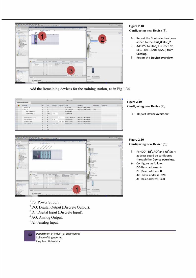
Add the Remaining devices for the training station, as in Fig 1.34
1PS: Power Supply.
2DO: Digital Output (Discrete Output).
3DI: Digital Input (Discrete Input).
4AO: Analog Output.
5AI: Analog Input.
21
Figure 2.18
Configuring new Device (3),
1- Report the Controller has been
added to the Rail_0 Slot_2.
2- Add PS1 to Slot_1. (Order No.
6ES7 307-1EA01-0AA0) from
Catalog.
3- Report the Device overview.
Figure 2.20
Configuring new Device (5),
1- For DO2, DI
3, AO
4 and AI
5 Start
address could be configured
through the Device overview.
2- Configure as follow:
DO Basic address 4
DI Basic address 0
AO Basic address 320
AI Basic address 300
1
Figure 2.19
Configuring new Device (4),
1- Report Device overview.

7/25/2019 Lab Manual v3
http://slidepdf.com/reader/full/lab-manual-v3 51/67
51 Department of Industrial Engineering
College of Engineering
King Saud University
2
1
2
3
Figure 2.21
Loading project (1),
1- Select PLC_1.
2- Select Download button.
3- Select MPI for Type of the
PG/PC interface.
Figure 2.22
Loading project (2),
1- Select Show all compatible
devices.
2- Select CPU 315-2 DP.
3- Select Load.
12
3
Figure 2.23
Loading project (3),
1- Select Consistent
download.
2- Select Load. 1
2

7/25/2019 Lab Manual v3
http://slidepdf.com/reader/full/lab-manual-v3 52/67
52 Department of Industrial Engineering
College of Engineering
King Saud University
3
Figure 2.24
Develop First LAD Network in
Main Block OB1 (1),
1- Select PLC_1
Program Blocks
Main [OB1]
2- Report Network 1 created
automatically.
3- Report the Basic Instructions
menu.
1
2
Figure 2.25
Develop First LAD Network inMain Block OB1 (2),
4- Insert Normally open contact
symbol for discrete input
device with address of I3.1
5- Insert Assignment symbol for
normally open coil discrete
output with address of Q4.6
6- Download Program, Set PLC to
RUN mode.
7- Set Monitor Mode and press
switch (I3.1) and report the
result.
1 2

7/25/2019 Lab Manual v3
http://slidepdf.com/reader/full/lab-manual-v3 53/67
53 Department of Industrial Engineering
College of Engineering
King Saud University
Table 2.1: Complete the Following tasks and obtain LAB supervisor
signature for each
Sub-
Task no.
Task Name Signature
1 Equality: SW1=Output1
2 AND gate: SW1.SW2
3 OR gate: SW1+SW2
4 NOT gate: SW1 BAR
5 R/S Memory : SW1-set, SW2-reset
6 R/S Memory: (SW1.SW2)-set, SW2-reset
7 R/S Memory:(SW1+SW2)-set, SW3 reset
8 R/S Memory: SW1-set, (SW2.SW3)-reset
9 R/S Memory: SW1-set,(SW2+SW3)-reset
10 R/S Memory: A-Cylinder movement: SW1-set,d+reset
11 R/S Memory: D-Cylinder movement: d--set, d-reset
12 R/S Memory: D-Cylinder movement: d--set, d-reset ,
SW4 enable
13 R/S Memory: A-Cylinder moment using two solenoid
valves: A+,A-

7/25/2019 Lab Manual v3
http://slidepdf.com/reader/full/lab-manual-v3 54/67
54 Department of Industrial Engineering
College of Engineering
King Saud University
task:
Pneumatic Network
Ex eriment 3
UNIT 2

7/25/2019 Lab Manual v3
http://slidepdf.com/reader/full/lab-manual-v3 55/67
55 Department of Industrial Engineering
College of Engineering
King Saud University
2.4 Pneumatic networks (Experiment 3).
2.4.1 Objectives
1. Identify main components of pneumatic power networks.
2. Identify pneumatic actuators with liner and angular displacements, types and ISO-
ANSI symbols.
3. Identify the pneumatic switching valves, types and ISO-ANSI symbols.
4. Identify pneumatic logic gates and development of pneumatic memory elements.
2.4.2 Outcomes of Laboratory Exercise
Upon completion of this laboratory exercise the student would able to understand how to
work with main pneumatic components and how to develop very simple pneumaticnetworks commonly used in industries.
2.4.3 Requirements
Complete the following tasks shown in the tabled form and get the supervisorsignature for each sub-task.

7/25/2019 Lab Manual v3
http://slidepdf.com/reader/full/lab-manual-v3 56/67
56 Department of Industrial Engineering
College of Engineering
King Saud University
Table 2.2: Complete the Following tasks and obtain LAB supervisor
signature for each
Sub-
Task no.
Task Name Signature
1 Identify 3x2 directional valve (Two types: push button
valve and limit valve.
2 Identify 5x2 directional valve (Four types: push
button valve, limit valve, solenoid and pilot line
valves).
3 Identify single and double acting cylinders (linear
displacement and angular displacement)
4 Identify pneumatic pressure regulator unit and try to
adjust the pressure.
5 Develop R/S pneumatic unit to drive double acting
cylinder using two 3x2 push button valves and 5x2
pilot line valve as memory unit.
6 Develop the pneumatic machine cycle for two double
acting cylinders A and B given as follows:
START, A+, B+,A-
B-

7/25/2019 Lab Manual v3
http://slidepdf.com/reader/full/lab-manual-v3 57/67
57 Department of Industrial Engineering
College of Engineering
King Saud University
Electric logic sensor and actuators
Ex eriment 4
UNIT 2

7/25/2019 Lab Manual v3
http://slidepdf.com/reader/full/lab-manual-v3 58/67
58 Department of Industrial Engineering
College of Engineering
King Saud University
2.5 Electric logic sensor and actuators and wiring them to PLC
(Experiment 4)
2.5.1 Experimental objectives The main objective from current experiment is the understanding type of electric
logic sensor and actuators. Also, how these type electric sensors are connected
and wired to PLC discrete input ports.
Five sensors where considered mainly, contact switches, proximity sensor and photoelectric sensors (three types).
For logic actuators, two types considered: Pneumatic solenoid valve and
electromechanical relay.
Memory element to be used to set the two type outputs using the given electriclogic sensors (contact, induction proximity, capacity proximity, photoelectric
three types)
2.5.2 Outcomes of Laboratory Exercise
Upon completion of this laboratory exercise the student would able to understand how to
work with main electric logic sensors and actuators and how to wire them to PLC.
2.5.3 Requirements
Identify the main electric logic sensors available in the laboratory (contact switch, proximity “two types’ inductive and capacitive types”, photo-detectors “three
types through beam, reflection from target and retro-reflection”).
Identify the main electric logic actuators available in laboratory(electromechanical relay and solenoid valve “many types)
Connect some of the proximity detectors to PLC input terminal and write small program showing how the sensor can be used in the control network.
Complete the sub-task required and get the supervisor signature for each task.

7/25/2019 Lab Manual v3
http://slidepdf.com/reader/full/lab-manual-v3 59/67
59 Department of Industrial Engineering
College of Engineering
King Saud University
Table 2.3: Complete the Following tasks and obtain LAB supervisor
signature for each
Sub-
Task no.
Task Name Signature
1 Identify different types of electric logic sensors
(contact type “NO and NC”, proximity “two types”,
reed switch, and optical “three types”)
2 Wire them to PLC and report the application of eachtype.
3 Identify electromechanical relay and solenoid
switching elements
4 Report some of them has mechanical memory while
other didn’t have.
5 Connect electromechanical relay to one of PLCoutput and develop R/S memory network to drive the
electromechanical relay using two push button
contact switches.
6 Repeat step 5, for two types of solenoid valves (with
and without mechanical memory)
7/25/2019 Lab Manual v3
http://slidepdf.com/reader/full/lab-manual-v3 60/67
60 Department of Industrial Engineering
College of Engineering
King Saud University
PLC, RLL programming using CASCADE Method
Ex eriment 5
UNIT 2

7/25/2019 Lab Manual v3
http://slidepdf.com/reader/full/lab-manual-v3 61/67
61 Department of Industrial Engineering
College of Engineering
King Saud University
2.6 PLC, RLL programming using CASCADE method (Experiment 5)
2.6.1 Experimental objectives
The main objective from current experiment is the understanding type RLL programming using CASCADE method.
Five common industrial machine sequences considered in current experiment.
2.6.2 Outcomes of Laboratory Exercise
Upon completion of this laboratory exercise the student would able to understand how to
design RLL control program using CASCADE method. Theoretical background on
CASCADE method is given in the course lecture.
2.6.3 Requirements
Develop the RLL program and check program execution for five commonmachine sequences discussed in theory given in lectures.
Complete the sub-task required and get the supervisor signature for each task.
Figure 2.26

7/25/2019 Lab Manual v3
http://slidepdf.com/reader/full/lab-manual-v3 62/67
62 Department of Industrial Engineering
College of Engineering
King Saud University
Table 2.4: Complete the Following tasks and obtain LAB supervisor
signature for each
Sub-Task
no.
Task Name Signature
1 Single path machine sequence:
START , A+, A-, B+, C+, B-, C-.
2 Parallel machine path:
START , A+, A-, , A-, B-, C-.
3 Parallel machine path with selection option:
START , A+, A-
4 Single machine path with option selection:
START , A+, ,A-
5 Single path with repeat option:
START , A+,(Repeat (B+,C+,B-,C-) until (xp=1)), A-
A+, B+
C+
Xp=1 (B+,B-, C+)
Xp=0 (B+, C+, B-)
Xp=1 (B+,B-)
Xp=0 (by pass)

7/25/2019 Lab Manual v3
http://slidepdf.com/reader/full/lab-manual-v3 63/67
63 Department of Industrial Engineering
College of Engineering
King Saud University
PLC timer, counter,registers and analog input/output functions
Ex eriment 6
UNIT 2

7/25/2019 Lab Manual v3
http://slidepdf.com/reader/full/lab-manual-v3 64/67
64 Department of Industrial Engineering
College of Engineering
King Saud University
2.7 PLC timer, counter, registers and analog input/output functions
(Experiment 6).
2.7.1 Experimental objectives
The main objective from current experiment is the understanding type RLL programming using CASCADE method.
Five common industrial machine sequences considered in current experiment.
2.7.2 Outcomes of Laboratory Exercise
Upon completion of this laboratory exercise the student would able to understand how to
design RLL control program using CASCADE method. Theoretical background onCASCADE method is given in the course lecture.
2.7.3 Requirements
Develop the RLL program and check program execution for five commonmachine sequences discussed in theory given in lectures.
Complete the sub-task required and get the supervisor signature for each task.

7/25/2019 Lab Manual v3
http://slidepdf.com/reader/full/lab-manual-v3 65/67
65 Department of Industrial Engineering
College of Engineering
King Saud University
Example 8 1:
Develop RLL program using 10 seconds Duration for Controlling output Q0.6
Through input contact switch I3.1 . in the follow cases:
- Pulse function 10s
- ON Delay 10s
- OFF Delay 10s
- ON Delay 10s and OFF Delay 10s
Example 8 5 ; Develop RLL for the given machine sequence using non-sustain
and sustain output signals ? Draw the sequencing chart of the machine
sequence for both cases?
Machine control sequence:
START, A+, 10s delay, A-, B+, 10s delay, C+, B-, C-.
Figure 2.27 Timer Functions symbols

7/25/2019 Lab Manual v3
http://slidepdf.com/reader/full/lab-manual-v3 66/67
66 Department of Industrial Engineering
College of Engineering
King Saud University
Example 8 8 : Modify example 7.4, see Chapter 7, to have specific repeated
number of cycles using counter function, e.g. 5 repeated cycles. Modify the same
RLL to have this feature. The machine cycle can be rewritten again as follows:
.,),,,(5,, AC BC Bcyclesrepeat ASTART

7/25/2019 Lab Manual v3
http://slidepdf.com/reader/full/lab-manual-v3 67/67
Table 2.5: Complete the Following tasks and obtain LAB supervisor
signature for each
Sub-Task
no.
Task Name Signature
1 Example 8.1 (TP timer function)
2 Example 8.1 (TON timer function)
3 Example 8.1 (TOF timer function)
4 Example 8.1(TON and TOF functions)
5 Example 8.5 (NON-Sustain)
6 Example 8.5 (Sustain outputs)
7 Example 8.8