Embed Size (px)
Citation preview

Department of Mechanical Engineering
LAB MANUAL
FOR
PRODUCTION ENGINEERING LAB II
DEPT. OF MECHANICAL ENGINEERING
Downloaded from Official website of Ammini College of Engineering, Palakkad http://ammini.edu.in/content.aspx?pageid=362

Lab Manual Production Engg. Lab II
1Ammini College of Engineering Dept. of Mechanical Engg.
1. SHAPER
1.1 INTRODUCTION The shaper is a reciprocating type of machine tool intended primarily to produce flat surfaces.
These surfaces may be horizontal, vertical, or inclined.
1.2 TYPES OF SHAPERS Shapers are classified in a number of ways depending upon the general features of design or
the purpose for which they are intended. Shapers are classified under the following headings.
a) According to the type of mechanism used for giving reciprocating motion to the ram: (a)
Crank type (b) Geared type (c) Hydraulic type.
b) According to the position and travel of ram: (a) Horizontal type (b) Vertical type (c)
Traveling head type.
c) According to the type of design of the table : (a) Standard shaper (b) Universal shaper d) According to the type of cutting stroke: (a) Push type (b) Draw type.
1.2.1 CRANK SHAPER - The most common type of shaper is Crank Shaper in which a single
point cutting tool is given a reciprocating motion equal to the length of the stroke
desired while the work is clamped in position on an adjustable table. In construction, the
crank shaper employs a crank mechanism to change circular motion of a large gear called
"bull gear" incorporated in the machine to reciprocating motion of the ram. The bull gear
receives power either from an individual motor or from an overhead line shaft if it is a belt
driven shaper.
1.2.2 HORIZONTAL SHAPER - In a horizontal shaper, the ram holding the tool reciprocates
in a horizontal axis
1.2.3 UNIVERSAL SHAPER - In a universal shaper, in addition to the two movements
provided on the table of a standard shaper, the table can be swiveled about an axis parallel to
the ram ways, and the upper portion of the table can be tilted about a second horizontal axis
perpendicular to the first axis. As the work mounted on the table can be adjusted in different
planes, the machine is most suitable for different types of work and is given the name
"Universal". A universal shaper is mostly used in tool room work.
Downloaded from Official website of Ammini College of Engineering, Palakkad http://ammini.edu.in/content.aspx?pageid=362

Lab Manual Production Engg. Lab II
2Ammini College of Engineering Dept. of Mechanical Engg.
1.2.4 PUSH TYPE SHAPER - This is the most general type of shaper used in common
practice. The metal is removed when the ram moves away from the column, i.e. pushes the
work.
1.2.5 DRAW TYPE SHAPER - In a draw shaper, the metal is removed when the ram moves
towards the column of the machine, i.e. draws the work towards the machine.
1.3 PRINCIPAL PARTS OF A SHAPER Figure below illustrates different parts of a standard shaper.
1.3.1 BASE The base is the necessary bed or support required for all machine tools. The base may be
rigidly bolted to the floor of the shop or on the bench according to the size of the machine. It
is so designed that it can take up the entire load of the machine and the forces set up by the
cutting tool over the work. It is made of cast iron to resist vibration and take up high
compressive load.
1.3.2 COLUMN The column is a box like casting mounted upon the base. It encloses the ram driving
mechanism. Two accurately machined guide ways are provided on the top of the column on
which the ram reciprocates. The front vertical face of the column which serves as the
Downloaded from Official website of Ammini College of Engineering, Palakkad http://ammini.edu.in/content.aspx?pageid=362

Lab Manual Production Engg. Lab II
3Ammini College of Engineering Dept. of Mechanical Engg.
guide ways for the cross rail is also accurately machined. The lid on the left side of the column
Downloaded from Official website of Ammini College of Engineering, Palakkad http://ammini.edu.in/content.aspx?pageid=362

4Ammini College of Engineering Dept. of Mechanical Engg.
Lab Manual Production Engg. Lab II
may be opened for inspection and oiling of the internal mechanism with the column. The
other side of the column contains levers, handles, etc. for operating the machine.
1.3.3 CROSS RAIL The cross rail is mounted on the front vertical guide ways of the column. It has two parallel
guide ways on its top in the vertical plane that are perpendicular to the ram axis. The table
may be raised or lowered to accommodate different sizes of jobs by rotating an elevating
screw which causes the cross rail to slide up and down on the vertical face of the column. A
horizontal cross feed screw which is fitted within the cross rail and parallel to the top guide
ways of the cross rail actuates the table to move in a crosswise direction.
1.3.4 SADDLE The saddle is mounted on the cross rail which holds the table firmly on its top. Crosswise
movement of the saddle by rotating the cross feed screw by hand or power causes the table to
move sideways.
1.3.5 TABLE The table which is bolted to the saddle receives crosswise and vertical movements from the
saddle and crosswise. It is a box like casting having T-Slots both on the top of the sides for
clamping the work
1.3.6 RAM The ram is a reciprocating member of the shaper. This is semi - cylindrical in form and
heavily ribbed inside to make it more rigid. It slides on the accurately machined dovetail
guide ways on the top of the column and is connected to the reciprocating mechanism
contained within the column.
1.3.7 TOOL HEAD The tool head of a shaper holds the tool rigidly, provides vertical and angular feeds
movement of the tool and allows the tool to have an automatic relief during its return stroke.
The vertical slide of the tool head has a swivel base which is held on a circular seat on the
ram. The swivel base is graduated in degrees, so that the vertical slide may be set
perpendicular to the work surface or at any desired angle. Apron consisting of clapper box,
dapper block md tool post is clamped up the vertical slide by a screw. The two vertical walls
on the apron called clapper box houses the clapper block which is connected to it by means of a
Downloaded from Official website of Ammini College of Engineering, Palakkad http://ammini.edu.in/content.aspx?pageid=362

Amm
Lab M
hinge
moun
On th
rigid t
block
dragg
dragg
1.4 The s
range
of the
power
numb
1.5 In a s
mini College o
Manual
pin. The to
nted upon th
he forward
tool suppor
k- out of th
ging and con
ging.
SHAPER
size of a sha
s from l75
e shaper. Ot
r input, flo
ber and amou
SHAPER
shaper, rota
of Engineerin
ool post is
he clapper bl
cutting stro
rt. On the re
he clapper
nsequent w
R SIZE
aper is dete
to 900mm.
ther particu
oor space r
unt of feed
R MECHA
ary moveme
ng
lock.
Figure
oke the clap
eturn stroke
box a suff
wear. The w
ermined by
The length
lars such as
required, w
etc. are also
ANISM
ent of the d
5
: Tool Head
pper block
e a slight fri
ficient amo
work surface
the length
h of stroke
s the type o
weight of th
o sometimes
drive is con
d of a Shap
fits secure
ictional drag
ount preven
e is also pre
of stroke o
of a shaper
of drive: bel
he machine
s necessary.
nverted into
Dep
P
per
ely to the c
g of the too
nting the to
evented fro
r cut it can
r merely ind
lt drive or in
e, cutting t
.
o reciprocat
ept. of Mecha
Production E
lapper box
ol on the wo
ool cutting
m any dam
n make. The
dicates the o
ndividual m
to return st
ting movem
anical Engg.
Engg. Lab II
to make a
ork lifts the
edge from
mage due to
e usual size
overall size
motor drive,
troke ratio,
ment by the
a
m
e
e
e
Downloaded from Official website of Ammini College of Engineering, Palakkad http://ammini.edu.in/content.aspx?pageid=362
6Ammini College of Engineering Dept. of Mechanical Engg.
Lab Manual Production Engg. Lab II
mechanism within the column of the machine. The ram holding the tool gets the reciprocating
movement. In a standard shaper metal is removed in the forward cutting stroke, while the
return stroke goes idle and no metal is removed during this period. To reduce the total
machining time it is necessary to reduce the time taken by the return stroke. The shaper
mechanism should be designed that it can allow the ram holding the tool to move at a
comparatively slower speed during the forward cutting stroke. During the return stroke it can
allow the ram to move at a faster rate to reduce the idle return time. This mechanism is
known as quick return mechanism. The reciprocating movements of the ram and the quick
return mechanism of the machine are usually obtained by anyone of the following methods.
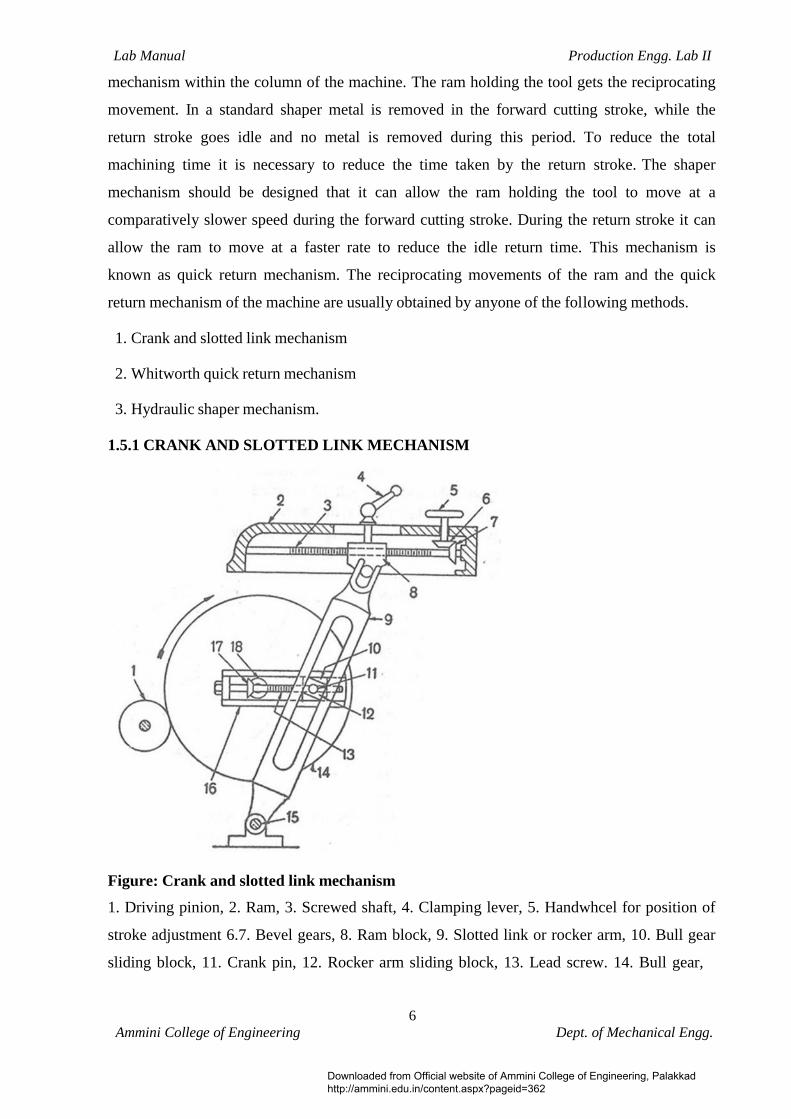
1. Crank and slotted link mechanism 2. Whitworth quick return mechanism 3. Hydraulic shaper mechanism. 1.5.1 CRANK AND SLOTTED LINK MECHANISM
Figure: Crank and slotted link mechanism
1. Driving pinion, 2. Ram, 3. Screwed shaft, 4. Clamping lever, 5. Handwhcel for position of
stroke adjustment 6.7. Bevel gears, 8. Ram block, 9. Slotted link or rocker arm, 10. Bull gear
sliding block, 11. Crank pin, 12. Rocker arm sliding block, 13. Lead screw. 14. Bull gear,
Downloaded from Official website of Ammini College of Engineering, Palakkad http://ammini.edu.in/content.aspx?pageid=362

7Ammini College of Engineering Dept. of Mechanical Engg.
Lab Manual Production Engg. Lab II
15. Rocker arm pivot, 16. Bull gear slide, 17. Bevel gears. The motion or power is transmitted to the bull gear 14 through a pinion 1 which receives its
motion from an individual motor. Speed of the bull gear may be changed by different
combination of gearing or by simply shifting the belt on the step cone pulley. Bull gear is a
large gear mounted within the column. Bolted to the centre of the bull gear is a radial slide 16
which carries a sliding block 10 into which the crank pin 11 is fitted.
Rotation of the bull gear will cause the crank pin to receive a uniform speed. Sliding block 12
which is mounted upon the crank pin is fitted within the slotted link 9. The slotted link also
known as rocker arm is pivoted at 15 at its bottom end attached to the frame of the column.
The upper end of the rocker arm is forked and connected to the ram block 8 by a pin. As the
bull gear rotates causing the crank pin to rotate, the sliding block 12 fastened to the crank pin
will rotate on the crank pin circle, and at the same time will move up and down the slot in the
slotted link 9 giving it a rocking movement which is communicated to the ram. Thus the
rotary motion of the bull gear is converted to reciprocating movement of the ram.
Figure: Principle of Quick Return Mechanism
When the link is in the position PM, the ram will be at the extreme backward position of its
stroke, and when it is at PN, the extreme forward position of the ram will have been reached.
PM and PN are drawn target to the crank pin circle. The forward cutting stroke, therefore,
takes place when the crank rotates through the angle C1KC2 and the return stroke takes place
when the crank rotates through the angle C2LC1. It is evident that the angle C1KC2 made by
the forward or cutting stroke is greater than the angle C2LC1 described by the return stroke.
The angular velocity of the crank pin being constant the return stroke as therefore, completed
within a shorter time for which it is known as quick return motion.
Downloaded from Official website of Ammini College of Engineering, Palakkad http://ammini.edu.in/content.aspx?pageid=362

8Ammini College of Engineering Dept. of Mechanical Engg.
Lab Manual Production Engg. Lab II
1.6 FEED MECHANISM In a shaper both down feed and cross feed movements are provided intermittently and during
the end of return stroke only. Vertical or bevel surfaces are produced by rotating the down
feed screw of the tool head by hand. Cross feed movement is used to machine a flat
horizontal surface. This is done by rotating the cross feed screw either by hand or power.
Rotation of the cross feed screw causes the table mounted upon the saddle to move sideways
through a predetermined amount.
Figure below illustrates the automatic cross feed mechanism of a shaper. The rotation of the
bull gear causes the driving disc 8 to rotate in a particular direction. The driving disc 8 is T-
slotted and position of the cranky pin 9 attached to the connecting rod may be altered to give
different throw of eccentricity.
Figure: Automatic feed mechanism of a shaper
1. Knob, 2. Pin, 3. Helical spring, 4. Pawl, 5. Ratchet wheel, 6. Rocker arm fulcrum,
7. Rocker arm connecting pin, 8. Driving disc, 9. Crank pin. The other end of the connecting rod is attached to the rocking arm by a pin 7. The rocking
arm is fulcrumed at 6, the centre of the ratchet wheel 5. The ratchet wheel 5 is keyed to the
cross feed screw. The rocking arm houses a spring loaded pawl 4 which is straight on one side
and bevel on the other side. As the driving disc rotates, the connecting rod starts reciprocating
and the rocking arm rocks on the fulcrum 6. When the driving disc rotates through half of the
revolution in the clockwise direction, top part of the rocking arm moves in the clockwise
direction and the pawl 4 being slant on one side slips over the teeth of the ratchet wheel 5
Downloaded from Official website of Ammini College of Engineering, Palakkad http://ammini.edu.in/content.aspx?pageid=362

9Ammini College of Engineering Dept. of Mechanical Engg.
Lab Manual Production Engg. Lab II
imparting it no movement.
As the driving disc rotates through the other half, the top of the rocking arm now moves in
the anticlockwise direction and the straight side of the pawl engages with the teeth of the
ratchet wheel causing the wheel to move in anticlockwise direction only. As the driving disc
is connected to the bull gear the table feed movement is effected when the bull gear or the
driving disc rotates through half of the revolution, i.e., during return stroke only. Rotation
through other half imparts no feed movement. To reverse the direction of rotation of ratchet
wheel and consequently the feed, a knob 1 on the top of the pawl 4 after removing the pin 2
is rotated through 180 degrees. The amount of feed may be altered by shifting the position of
crank pin 9 with respect to the centre.
1.7 SHAPER OPERATIONS A shaper is a versatile machine tool primarily designed to generate a flat surface by a single
point cutting tool. But it may also be used to perform many other operations. The different
operations which a sharper can perform are as follows:
1. Machining horizontal surface. 2. Machining vertical surface. 3. Machining angular surface. 4. Cutting slots, grooves, and key ways. 5. Machining irregular surface. 6. Machining splines or cutting gears. 1.8 WORK HOLDING DEVICES The work may be supported on the table by the following methods depending on the nature of
the work piece.
1. Clamped in a vise 2. Clamped on the table 3. Clamped to the angle plate 4. Clamped on a V-block 5. Held between shaper index centre
Downloaded from Official website of Ammini College of Engineering, Palakkad http://ammini.edu.in/content.aspx?pageid=362

1Ammini College of Engineering Dept. of Mechanical Engg.
Lab Manual Production Engg. Lab II
1.8.1 SHAPER VISES Figure below illustrates a typical shaper vise. A vise is a quick method of holding and
locating relatively small and regular shaped work pieces. It consists of a base, table, screw,
fixed and movable jaws. The work is clamped between fixed and movable jaws by rotating
the screw.
Figure: Shaper Vise
1. Screw, 2. Movable jaw, 3. Hold down, 4. Work 5. Parallels, 6. Handle 1.9 SHAPER TOOLS
The cutting tool used in a shaper is a single point cutting tool having rake, clearance and
other tool angles similar to a lathe tool. It differs from a lathe tool in tool angles. Shaper tools
are much more rigid and heavier to withstand shock experienced by the cutting tool at the
commencement of each cutting stroke. In a lathe tool the effective angle of rake and clearance
may be varied by raising or lowering the point of the tool in relation to the centre of the work,
but in a shaper the tool angles cannot be changed as the tool is always clamped
perpendicular to the surface of the work. As the tool removes metal mostly from its side
cutting edge, side rake of 10° is usually provided with little or no front rake. The side rake
angle to be provided is dependent upon the kind of metal being cut, the hardness of the tool
material, type of cut and other factors which influence the rake angle. A shaper can also use a
right hand or left hand tool. The left hand tool is more common because it permits the
operator to see the cut better than the right hand tool. High speed steel is the most common
material for a shaper tool but shock resistant cemented carbide tipped tool is also used where
harder material is to be machined.
Downloaded from Official website of Ammini College of Engineering, Palakkad http://ammini.edu.in/content.aspx?pageid=362

Lab Manual Production Engg. Lab II
10Ammini College of Engineering Dept. of Mechanical Engg.
2. SLOTTING MACHINE
2.1 INTRODUCTION A slotting machine or slotter is used for cutting different types of slots and it certainly proves
to be most economical. Its other uses are in machining irregular shapes, circular surfaces and
other premarked profiles. Its construction is similar to that of a vertical shaper. Its ram moves
vertically and the tool cuts during the downward stroke only.
2.2 YPES OF SLOTTER 2.2.1 PUNCHER SLOTTER The puncher slotter is a heavy rigid machine designed for removal of large amount of metal
from large forgings or castings. The length of stroke of a puncher slotter is sufficiently large.
2.2.2 PRECISION SLOTTER The precision slotter is a lighter machine and is operated at high speeds. The machine is
designed to take light cuts giving accurate finish. The precision machines are also used for
general purpose work and are usually fitted with whit worth quick return mechanism.
2.3 LOTTER SIZE The size of a slotter like that of a shaper is specified by the maximum length of stroke of the
ram expressed in mm. The size of a general purpose or precision slotter usually ranges from
80 to 900 mm. To specify a slotter correctly the diameter of the table in mm, amount of cross
and longitudinal travel of the table expressed in mm, number of speeds and feeds available,
h.p of the motor, floor space required etc. should also be stated. 2.4 SLOTTING MACHINE PARTS 2.4.1 BASE OR BED The base is rigidly built to take up all the cutting forces and entire load of the machine. The
top of the bed is accurately finished to provide guide ways on which the saddle is mounted.
2.4.2 COLUMN The column is a vertical member which is cast integral with the base and houses driving
mechanism of the ram and feeding mechanism.
Downloaded from Official website of Ammini College of Engineering, Palakkad http://ammini.edu.in/content.aspx?pageid=362

10Ammini College of Engineering Dept. of Mechanical Engg.
Lab Manual Production Engg. Lab II
The front vertical face of the column is accurately finished for providing ways on which the
ram reciprocates.
Figure: Slotting Machine 1. Base, 2. Feed gear, 3. Cross-slide, 4. Table, 5. Cross feed handle, 6. Longitudinal feed Handle, 7. Circular feed handle, 8. Tool, 9. Ram, 10. Crank disc, 11. Lever for counterbalance weight, 12. Bull gear, 13. Cone pulley, 14. Column, 15. Feed shaft, 16. Pawl actuating crank.
2.4.3 SADDLE The saddle is mounted upon the guide ways and may be moved towards or away from the
column either by power or manual control to supply longitudinal feed to the work. The top
face of the saddle is accurately finished to provide guide ways on the base.
2.4.4 CROSS SLIDE The cross slide is mounted upon the guide way of the saddle and may be moved parallel to
the face of the column.
Downloaded from Official website of Ammini College of Engineering, Palakkad http://ammini.edu.in/content.aspx?pageid=362

10Ammini College of Engineering Dept. of Mechanical Engg.
Lab Manual Production Engg. Lab II
2.4.5 ROTARY TABLE The rotary table is a circular table which is mounted on the top of the cross slide. The table
may be rotated by rotating a worm which meshes with a worm gear connected to the
underside of the table. In some machines the table is graduated in degree that enables the
table to be rotated for indexing or dividing the periphery of a job in equal lumber of parts. T-
slots are cut on the top face of the table for holding the work by different clamping devices.
2.4.6 RAM AND TOOLHEAD ASSEMBLY The ram is the reciprocating member of the machine mounted on the guide ways of the
column. It supports the tool at its bottom end on a tool head. A slot is cut on the body of the
ram for changing the position of stroke.
2.5 RAM DRIVE MECHANISM A slotter removes metal during downward cutting stroke only whereas during upwards return
stroke no metal is removed. The usual types of ram drive mechanisms are
1. Whitworth quick return mechanism
2. Variable speed reversible motor drive mechanism
3. Hydraulic drive mechanism. 2.5.1 WHITWORTH QUICK RETURN MECHANISM The Whitworth quick return mechanism is most widely used in medium sized slotting
machine for driving the ram. The bullgear 7 located at the back of the machine receives its
motion from the pinion 11 which is driven by an electric motor. The gear 7 is mounted on a
fixed pin or hub 9 attached to the machine frame. The driving plate 8 is mounted on the shaft
which passes through the fixed pin. The shaft 6 is placed eccentrically with respect to the
bullgear centre. A crank pin is mounted on the face of the bullgear which holds a slide block
10. The slide block is fitted within a radial slot provided by the inner side of the driving plate
8. As the bull gear rotates, the crank pin and the slide block rotate in a circular path, but
owing to the eccentricity of the bull gear and the driving plate, the slide block rotates and
slides within the slot of the driving plate imparting it and the shaft rotary movement. The
rotation of the driving plate is transmitted to the disc 5 which is attached to the end of the
shaft.
Downloaded from Official website of Ammini College of Engineering, Palakkad http://ammini.edu.in/content.aspx?pageid=362

10Ammini College of Engineering Dept. of Mechanical Engg.
Lab Manual Production Engg. Lab II
Figure: Whitworth quick return mechanism
1. Ram, 2. Connecting rod clamping bolt, 3. Pivot, 4. Counter balance weight,
5. Crank disc, 6. Driving shaft, 7. Bull gear, 8. Driving plate, 9. Fixed hub,
10. Crankpin with slide block, 11. Driving pinion. A radial T-slot is cut on the face of the disc. The position of the pin fitted within the T-slot
may be altered with respect to the centre of the disc and then clamped at one end of the
connecting rod. The other end of the connecting rod is attached to the ram 1 by a clamping
bolt 2. The rotation of the disc is converted into reciprocating movement of the ram by the
connecting rod and the pin eccentrically mounted on the disc.
2.6 FEED MOVEMENTS In a slotter, the feed is given by the table. A slotting machine table may have three types of
feed movements.
1. Longitudinal 2. Cross 3. Circular If the table is feed perpendicular to the column towards or away from its face, the feed
movements termed as longitudinal. If the table is feed parallel to the face of the column the
feed movement is termed as cross. If the table is rotated on a vertical axis, the feed movement
is termed as circular.
Downloaded from Official website of Ammini College of Engineering, Palakkad http://ammini.edu.in/content.aspx?pageid=362

10Ammini College of Engineering Dept. of Mechanical Engg.
Lab Manual Production Engg. Lab II
2.7 WORK HOLDING DEVICES
The work is held on a slotter table by a Vise, T-bolts and clamps of by special fixtures. T-
Bolts and clamps are used for holding most of the work on the table. Before clamping packing
pieces are place below the work so as to allow the tool to complete the cut without touching
the table.
2.8 LOTTER OPERATIONS The operations performed in a slotter are 1. Machining flat surfaces: 2. Machining cylindrical surfaces 3. Machining irregular surfaces and cam machining 4. Machining slots, keyways and grooves. 2.9 LOTTER TOOLS The tool in a slotter removes metal during its vertical cutting stroke. This changed cutting
condition presents a lot of difference, in the tool shape. In a slotter the cutting pressure acts
along the length of the tool. The rake and the clearance angle of a slotter tool apparently look
different from a lathe or a shaper tool as these angles are determined with respect to a vertical
plane rather than the horizontal. Slotter tools are provided with top rake front clearance and
side clearance, but no side rake is given. The-nose of the tool projects slightly beyond the
shank to provide clearance.
Downloaded from Official website of Ammini College of Engineering, Palakkad http://ammini.edu.in/content.aspx?pageid=362
10Ammini College of Engineering Dept. of Mechanical Engg.
Lab Manual Production Engg. Lab II
3. MILLING MACHINE
3.1 INTRODUCTION A milling machine is a machine tool that removes metal as the work is fed against a rotating
multipoint cutter. The cutter rotates at a high speed and because of the multiple cutting edges
it removes metal at a very fast rate. The machine can also hold one or more number of cutters
at a time.
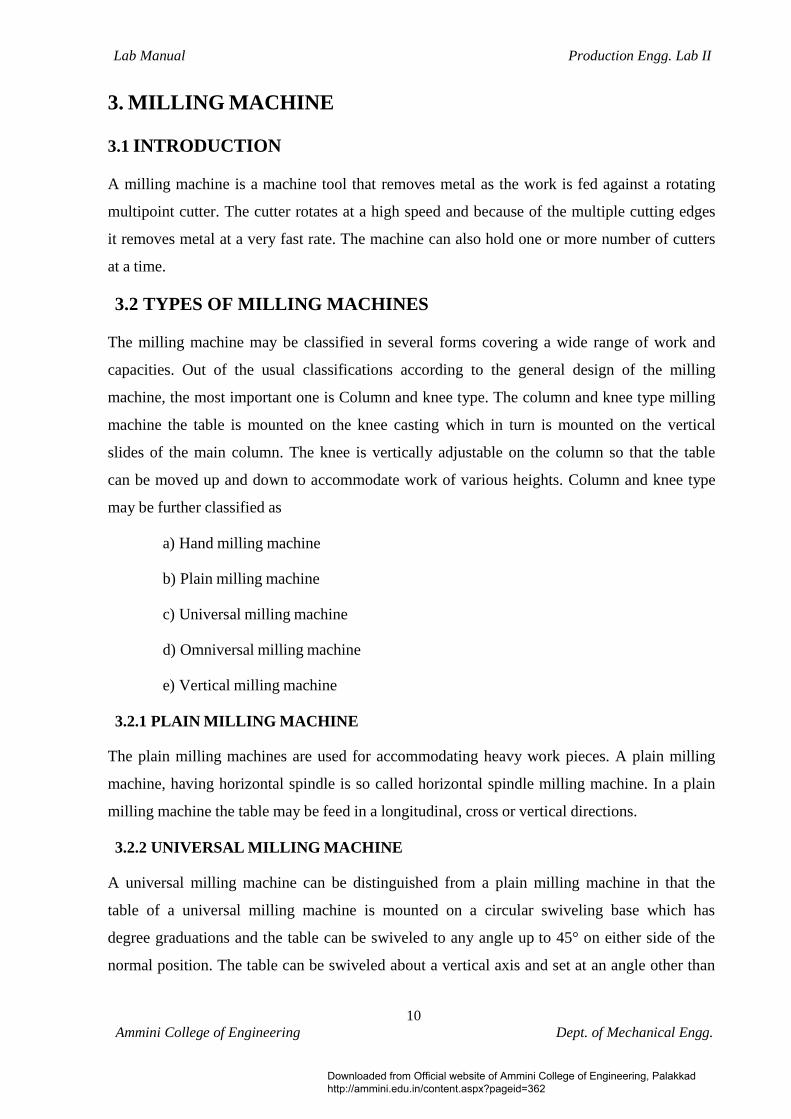
3.2 TYPES OF MILLING MACHINES The milling machine may be classified in several forms covering a wide range of work and
capacities. Out of the usual classifications according to the general design of the milling
machine, the most important one is Column and knee type. The column and knee type milling
machine the table is mounted on the knee casting which in turn is mounted on the vertical
slides of the main column. The knee is vertically adjustable on the column so that the table
can be moved up and down to accommodate work of various heights. Column and knee type
may be further classified as
a) Hand milling machine
b) Plain milling machine
c) Universal milling machine
d) Omniversal milling machine
e) Vertical milling machine 3.2.1 PLAIN MILLING MACHINE The plain milling machines are used for accommodating heavy work pieces. A plain milling
machine, having horizontal spindle is so called horizontal spindle milling machine. In a plain
milling machine the table may be feed in a longitudinal, cross or vertical directions.
3.2.2 UNIVERSAL MILLING MACHINE A universal milling machine can be distinguished from a plain milling machine in that the
table of a universal milling machine is mounted on a circular swiveling base which has
degree graduations and the table can be swiveled to any angle up to 45° on either side of the
normal position. The table can be swiveled about a vertical axis and set at an angle other than
Downloaded from Official website of Ammini College of Engineering, Palakkad http://ammini.edu.in/content.aspx?pageid=362

10Ammini College of Engineering Dept. of Mechanical Engg.
Lab Manual Production Engg. Lab II
right angles to the spindle. Thus in a universal milling machine, in addition to three
movements as incorporated in a plain milling machine, the table may have a fourth
movement when it is feed at an angle to the milling cutter. The capacity of a universal milling
machine is considerably increased by the use of special attachments such as dividing head,
vertical milling attachment, rotary attachment, slotting attachment etc. The machine can
produce spur, spiral, bevel gears, twist drills, reamers, milling cutters etc.
3.2.3 VERTICAL MILLING MACHINE A vertical milling machine the position of its spindle which is vertical or perpendicular to the
work table. The machine may be of plain or universal type and has all the movements of the
table for proper setting and feeding the work. The spindle head which is clamped to the
vertical column may be swiveled at an angle, permitting the milling cutter mounted on the
spindle to work on angular surfaces. The end mills and face milling cutters are the usual tools
mounted on the spindle.
3.3 PRINCIPAL PARTS OF A MILLING MACHINE
Figure: Column and Knee type milling machine
1. Base, 2. Elevating screw, 3. Knee, 4. Knee elevating handle, 5. Cross feed handle,
6. Saddle, 7. Table, 8. Front brace, 9, Arbor support, 10. Arbor, 12. Milling cutter,
14. Cone pulley, 15. Telescopic feed shaft.
Downloaded from Official website of Ammini College of Engineering, Palakkad http://ammini.edu.in/content.aspx?pageid=362

10Ammini College of Engineering Dept. of Mechanical Engg.
Lab Manual Production Engg. Lab II
3.3.1 BASE The base of the machine is a grey iron casting accurately machined on its top and bottom
surface and serves as a foundation member for all the other parts which rest upon it. In some
machines, the base is hollow and serves as a reservoir for cutting fluid.
3.3.2 COLUMN The column is the main supporting frame mounted vertically on the base. The column is box
shaped, heavily ribbed inside and houses all the driving mechanisms for the spindle and table
feed. The front vertical face of the column is accurately machined and is provided with
dovetail guide ways for supporting the knee. The top of the column is finished to hold an over
arm that extends the outward at the front of the machine.
3.3.3 KNEE The knee is a rigid grey iron casting that slides up and down on the vertical ways of the
column face. The adjustment of height is effected by an elevating screw, mounted on the base
that also supports the knee. The knee houses the feed mechanism of the table. The top face of
the knee forms a slide way for the saddle to provide cross travel of the table.
3.3.4 SADDLE On the top of the knee is placed the saddle, which slides on guide ways set exactly at 90° to
the column face. A cross feed screw near the top of the knee engages a nut on the bottom of
the saddle to move it horizontally, by hand or power. The top of the saddle is accurately
machined to provide guide ways for the table.
3.3.5 TABLE The table rests on base on the saddle and travel longitudinally. The top of the table is
accurately finished and T-slots are provided for clamping the work and other fixtures on it. A
lead screw under the table engages a nut on the saddle to move the table horizontally by hand
or by power.
3.3.6 OVER HANGING ARM The overhanging arm that is mounted on the top of the column extends beyond the column
face and serves as a bearing support for the other end of the arbor. The ram is adjustable so
that the bearing support may be provided nearest to the cutter.
Downloaded from Official website of Ammini College of Engineering, Palakkad http://ammini.edu.in/content.aspx?pageid=362

10Ammini College of Engineering Dept. of Mechanical Engg.
Lab Manual Production Engg. Lab II
3.3.7 FRONT BRACE The front brace is an extra support that is fitted between the knee and the over arm to ensure
further rigidity to the arbor and the knee. The front brace is slotted to allow for the adjustment
of the height of the knee relative to the over arm.
3.3.8 SPINDLE The spindle of the machine is located in the upper part of the column and receives power
from the motor through belts, gears and clutches and transmit it to the arbor. The front end of
the spindle just projects, from the column face and is provided with a tapered hole into which
various cutting tools and arbors may be inserted.
3.3.9 ARBOR An arbor may be considered as an extension of the machine spindle on which milling cutters
are securely mounted and rotated. The arbors are made with taper shanks for proper
alignment with the machine spindles having taper holes at their nose. The arbor may be
supported at the farthest end from the overhanging arm or may be of cantilever type which is
called stub arbor.
3.4 SIZE OF MILLING MACHINE The size of the column and knee type milling machine is designated by the dimensions of the
working surface of the table and its maximum length of longitudinal, cross and vertical travel
of the table. In addition to the above dimensions, number of spindle speeds, numbers of
feeds, spindle nose taper, power available, net weight, and the floor space required, etc.
should also be stated in order to specify the machine fully.
3.5 WORK AND CUTTER HOLDING DEVICES 3.5.1 WORK HOLDING DEVICES It is necessary that the work should be properly and securely held on the milling machine
table for effective machining operations. The following are the usual method of holding the
work on the table. 1. T-bolts and clamps 2. Angle plates 3. V-blocks
Downloaded from Official website of Ammini College of Engineering, Palakkad http://ammini.edu.in/content.aspx?pageid=362

10Ammini College of Engineering Dept. of Mechanical Engg.
Lab Manual Production Engg. Lab II
4. Vises
3.5.2 CUTTER HOLDING DEVICES There are several methods of supporting and rotating milling cutters with the machine
spindle, depending on the different designs of the cutters. The following are the different
devices for holding and rotating cutters.
1. Arbors 2. Adapters 3. Collets 4. Spring collets 5. Bolted cutters 6. Screwed on cutters. 3.6 MILLING MACHINE ATTACHMENTS The attachments are standard or special auxiliary devices intended to be fastened to or joined
with one or more components of the milling machine for the purpose of augmenting the
range, versatility, productivity or accuracy of operations. Some of them are used for
positioning and driving the cutter while the others are used for positioning, holding and
feeding the work along a specified geometric path. The following are the different
attachments used on standard column and knee type milling machine.
1. Vertical milling attachment 2. Universal milling attachment 3. High speed milling attachment 4. Slotting attachment 5. Universal spiral milling attachment 6. Rack milling attachment 7. Circular milling attachment 8. Dividing head attachment
Downloaded from Official website of Ammini College of Engineering, Palakkad http://ammini.edu.in/content.aspx?pageid=362

Lab Manual Production Engg. Lab II
20Ammini College of Engineering Dept. of Mechanical Engg.
3.7 MILLING MACHINE OPERATIONS The following are the different operations performed in a milling machine.
1. Face milling. 9. Plain milling
2.
Side Milling
10. Straddle milling
3.
Angular milling
11. Gang milling.
4.
Form milling
12. Profile milling
5.
End milling
13. Saw milling
6.
Thread milling
14. Cam milling
7.
Gear cutting
15. Helical milling.
8. Milling key ways, grooves and slots 3.8 MILLING CUTTERS The milling cutters are revolving tools having one or several cutting edges of identical form
equally spaced on the circumference of the cutter. The cutting elements arc called teeth which
intermittently engage the work piece and remove material by relative movements of the work
piece and cutter. Milling cutters may be classified as:
1. According to the constructional feature of the cutter (a) Solid cutter (b) Tipped solid cutter (c) Inserted teeth cutter 2. According to the relief characteristics of the cutter teeth (a) Profile relieved cutter (b) Form relieved cutter 3. According to the methods of mounting the cutter (a) Arbor type cutter (b) Shank type cutter (c) acing type cutter
Downloaded from Official website of Ammini College of Engineering, Palakkad http://ammini.edu.in/content.aspx?pageid=362
Lab Manual Production Engg. Lab II
21Ammini College of Engineering Dept. of Mechanical Engg.
4. According to the direction of rotation of the cutter. (a) Right hand rotational cutter (b) Left hand rotational cutter 5. According to the direction of helix of the cutter teeth (a) Parallel or straight teeth cutter (b) Right hand helical cutter (c) Left hand helical cutter (d) Alternate helical teeth cutter. 6. According to purpose or use of the cutter (a) Standard milling cutter (b) Special milling cutter 3.8.1 STANDARD MILLING CUTTER There are many different types of standard milling cutters. They are classified below 1. Plain milling cutter 2. Side milling cutter 3. Metal slitting saw 5. End mill 6. T slot milling cutter 7. Wood ruff key slot milling cutter 8. Fly cutter 9. Formed cutter 10. Tap and reamer cutter. 3.8.1.1 ELEMENTS OF A PLAIN MILLING CUTTER 1. Body of cutter The part of the cutter left after exclusion of the teeth and the portion to which the teeth are
attached.
Downloaded from Official website of Ammini College of Engineering, Palakkad http://ammini.edu.in/content.aspx?pageid=362

22Ammini College of Engineering Dept. of Mechanical Engg.
Lab Manual Production Engg. Lab II
2. Cutting edge The edge formed by the inter section of the face and the circular land.
Figure: Elements of a plain milling cutter 3. Face The portion of the gash adjacent to the cutting edge on which the chip impinges as it is cut
from the work.
4. Fillet The curved surface at the bottom of gash which joins the face of one teeth to the back of the
tooth immediately ahead.
5. Gash The chip space between the back of one tooth and the face of the next tooth. 6. Land The part of the back of tooth adjacent to the cutting edge. 7. Lead The axial advance of the helix of the cutting edge in one complete revolution of the cutter.
Downloaded from Official website of Ammini College of Engineering, Palakkad http://ammini.edu.in/content.aspx?pageid=362

23Ammini College of Engineering Dept. of Mechanical Engg.
Lab Manual Production Engg. Lab II
8. Outside diameter The diameter of the circle passing through the peripheral cutting edge 9. Root diameter The diameter of the circle passing through the bottom of the fillet. 10. Relief angle The angle in a plane perpendicular to the axis, which is the angle between the land of a tooth
and the tangent to the outside diameter of cutter at the cutting edge of that tooth.
11. Primary clearance angle The angle formed by the back of the tooth with a line drawn tangent to the periphery of the
cutter at the cutting edge.
12. Secondary clearance angle The angle formed by the secondary clearance surface of the tooth with a line drawn tangent to
the periphery of the cutter at the cutting edge.
13. Rake angle (Radial) The angle measured in the diametric plane between the face of the tooth and a radial line
passing through the tooth cutting edge. The rake angles which may be positive, negative or
zero.
14. Lip angle The included angle between the land and the face of the tooth, or alternatively the angle
between the tangent to the back at the cutting edge and the face of the tooth.
15. Helix angle The cutting edge angle which a helical cutting edge makes with a plane containing the axis of a
cylindrical cutter.
3.9 FUNDAMENTALS OF THE MILLING PROCESS 3.9.1 UPMILLING The upmilling, which is also called conventional milling, is the processes of removing metal
by a cutter which is rotated against the direction of travel of the work piece. The surface
milled by upmilling appears to be slightly wavy as the cutter teeth do not begin their cut as
Downloaded from Official website of Ammini College of Engineering, Palakkad http://ammini.edu.in/content.aspx?pageid=362

Lab Manual Production Engg. Lab II
30Ammini College of Engineering Dept. of Mechanical Engg.
soon as they touch the work surface. The upmilling process, being safer, is still commonly
used inspite of having so many disadvantages.
Figure: (a) Downmilling ( b) Upmilling
1. Direction of work feed, 2. Chip, 3. Machined surface, 4. Direction of rotation,
5. Start of cut, 6. Work surface, 7. Depth of cut, 8. Feed per tooth 3.9.2 DOWNMILLING The downmilling, which is also called climb milling, is the process of removing metal by a
cutter which is rotated in the same direction of travel of the work piece. Downmilling
operation cannot be used on old machines due to backlash error that may be present between
the feed screw of the table and nut. Downmilling should only be performed on rigid machines
provided with backlash eliminator.
3.10 GEAR CUTTING 3.10.1 GEAR CUTTING METHODS The most common and accurate method of production of gears is by machining. The different
methods of production of gears by machining operations are described below.
a) Formed cutter method
b) Template method in a gear cutting machine
c) Generating method
Downloaded from Official website of Ammini College of Engineering, Palakkad http://ammini.edu.in/content.aspx?pageid=362

Lab Manual Production Engg. Lab II
30Ammini College of Engineering Dept. of Mechanical Engg.
3.10.1.1GEAR CUTTING BY FORMED DISC CUTTER The method of gear cutting by a formed disc cutter involves the mounting of a gear blank at
the end of dividing head spindle fitted on the table of a horizontal, column and knee type
milling machine and then feeding the work past a rotating, formed, peripheral, type of cutter
mounted on the horizontal arbor of machine. The plane of rotation of the cutter is radial with
respect to the blank. After one tooth is formed, the next surface of the gear blank is brought
under the cutter by rotating the dividing head spindle by a predetermined amount by indexing.
The tooth profile of the formed cutter should correspond to the tooth space of the gear that
again depends upon the module of the gear.
3.10.2 INDEXING AND DIVIDING HEADS The indexing is the operation of dividing the periphery of a piece of work into any number of
equal parts. In cutting spur gear, equal spacing of teeth on the gear blank is performed by
indexing. The indexing operations can also be adapted for producing hexagonal and square
headed bolts, cutting splines on shafts, fluting drills, taps and reamers and many other jobs,
all requiring the periphery of the work piece to be divided equally and accurately. Indexing is
accomplished by using a special attachment known as dividing head or index head. The
dividing heads are of three types.
a) Plain or simple dividing head
b) Universal dividing head
c) Optical dividing head. 3.10.2.1 Plain or simple dividing head The plain dividing head comprises of a cylindrical spindle housed in a frame, and a base
bolted to the machine table. The index clank is connected to the tail-end of the spindle
directly, and the crank and the spindle rotate as one unit. The index plate is mounted on the
spindle and rotates with it. The spindle may be rotated through the desired angle and then
clamped by inserting the clamping lever pin into any one of the equally spaced holes or slots
cut on the periphery of the index plate. The work is mounted at the nose end of the spindle by a
chuck or may be supported between the two centres. This type of dividing head is used for
handling large number of work pieces, which requires very small number of divisions on the
periphery.
Downloaded from Official website of Ammini College of Engineering, Palakkad http://ammini.edu.in/content.aspx?pageid=362

Lab Manual Production Engg. Lab II
30Ammini College of Engineering Dept. of Mechanical Engg.
3.10.2.2 Universal dividing head
Universal dividing head shown in Figure below is the most common type of indexing arrangement used in workshops. As the name implies, this type of index head can be used to execute all forms of indexing.
The important parts of a universal dividing head are the worm and worm gear, index plate,
sector arm, change gears and the spindle. The working mechanism of a universal dividing
head is shown in Figure below. The main spindle 5 housed on two accurate bearings carries a
worm gear 4 is mounted on a shaft 10 at the other end of which a crank 13 is fitted. The
worm gear 4 has 40 teeth and the worm 6 is single threaded. Thus 40 turns of the crank 13
will rotate the spindle 5 through one complete revolution or one turn of the crank 13 will
cause the spindle 5 to be rotated by 1/40 of a revolution. In order to turn the crank 13 a
fraction of a revolution, an index plate 12 is used. An index plate is a circular disc having a
different number of equally spaced holes arranged in concentric circles. The index plate 12 is
screwed on a sleeve which is loosely mounted on the worm shaft 10. Normally, the index
plate 12 remains stationary by a lock pin 11 connected with the frame. A spring loaded pin 14
fixed to the crank 13 fits into the holes in the index plate 12. If the pin 14 is moved from one
hole to the next hole in a 18 hole circle of the index plate, the spindle 5 will revolve 1/40 ×
Downloaded from Official website of Ammini College of Engineering, Palakkad http://ammini.edu.in/content.aspx?pageid=362

Lab Manual Production Engg. Lab II
30Ammini College of Engineering Dept. of Mechanical Engg.
1/18 = 1/720 of a turn. The sector arms shown in figure is used to eliminate the necessity of
counting holes on the index plate each time the index crank is moved.
Figure: Working mechanism of a Universal dividing head
1, 2. Change gears, 3. Spindle stud, 4. Worm gear, 5. Spindle, 6. Worm, 7. Carrier, 8. Work,
9. Dead centre, 10. Worm shaft, 11. Lockpin, 12. Index plate, 13. Index crank,
14. Spring loaded pin, 15. Mitre gears, 16.Driven shaft.
3.10.2 INDEXING METHODS There are several methods of indexing. The choice of any method depends upon the number of
divisions required and the type of dividing head used. The following are the different methods
of indexing.
1. Direct or rapid indexing
2. Plain or simple indexing
3. Compound indexing
4. Differential indexing
5. Angular indexing
Downloaded from Official website of Ammini College of Engineering, Palakkad http://ammini.edu.in/content.aspx?pageid=362

Lab Manual Production Engg. Lab II
30Ammini College of Engineering Dept. of Mechanical Engg.
nk mo v
head t mil 0 te3 e aon spurExample: Set the dividing o l th wheel blank. Index crank movement = 1 1 1
3.10.2.1 Simple Indexing The simple indexing, sometimes called plain indexing, is more accurate and suitable for
numbers beyond the range of rapid indexing. Here, the dividing head spindle is moved by
turning the index crank 13, shown in Fig. above (universal dividing head). As the shaft 10
carrying the crank has a single threaded worm 6 which meshes with the worm gear 4 having
40 teeth, 40 turns of the crank 13 are necessary to rotate the index head spindle 5 through one
revolution. In other words, one complete turn of the index crank 13 will cause the worm
wheel 4 to make 1/40 of a revolution
To facilitate indexing to fractions of a turn, index plates are used to cover practically all
numbers. Index plates with circles of holes patented by the Brown and Sharp manufacturing
company are as follows:
Plate No. 1 - 15, 16, 17, 18, 19, 20
Plate No. 2 - 21, 23, 27, 29, 31, 33
Plate No. 3 - 37, 39, 41, 43, 47, 49
These plates have also been accepted as standard index plates by the Indian machine tool
manufacturers.
Rule for simple indexing: To find the index crank movement, divide 40 by the number of
divisions required on the work.
The formula for index cra ement is given
below: Index crank movement =
Where, N = number of divisions required
If the index crank movement deduced from the above formula is a whole number, the index
crank should be rotated through a complete number of turns equal to the derived whole
number. If the index crank movement deduced from the equation is a whole number and a
fraction, the numerator and the denominator of the fraction after simplifying are multiplied by a
suitable common number which will make the denominator of the fraction equal to the
number of holes in the index plate circle. The new numerator now stands for the number of
holes to be moved by the index crank in the hole circle derived from the denominator, in
addition to the complete turns of the index crank. Thus for indexing, one complete turn and 7 holes in 21 hole circle of the index plate will have
Downloaded from Official website of Ammini College of Engineering, Palakkad http://ammini.edu.in/content.aspx?pageid=362

Lab Manual Production Engg. Lab II
30Ammini College of Engineering Dept. of Mechanical Engg.
to be moved by the index crank.
4. GRINDING MACHINES
4.1 INTRODUCTION Grinding is a process of material removal in the form of small chips by the mechanical action
of abrasive particles bonded together in a grinding wheel. It is basically a finishing process
employed for producing close dimensional and geometrical accuracies and smooth surface
finish. However in same applications, the grinding process is also applied for higher material
removal rates and is referred to as abrasive machining. Generally, in other methods of
machining, the work piece is shaped by removing chips using cutting tools having designed
geometry, with the tool material is harder than the work material. In such types of machining
the process has the following limitations.
1) The difference in the hardness of the tool and of the work is often limited, resulting tool
wear and tool failure.
2) In the process of removing materials by way of chips, a considerable amount of heat is
generated which, when it exceeds a specific level, affects the tool hardness. These conditions
always limit the applicable cutting speed.
4.2 TYPES OF GRINDING Grinding is done on surfaces of almost all conceivable shapes and materials of all kinds.
Grinding may be classified broadly into two groups.
1. Rough or non-precision grinding. 2. Precision grinding.
4.2.1 ROUGH GRINDING
The common forms of rough grinding are snagging and off-hand grinding where the work is
held in the operators hand. The work is pressed hard against the wheel, or vice -versa. The
accuracy and surface finish obtained are of secondary importance.
Snagging is done where; a considerable amount of metal is removed without regard to the
accuracy of the finished surface. Examples of snag grinding are trimming the surface left by
sprues and risers on castings, grinding the parting line left on castings, removing flash on
forgings, the excess metal on welds, cracks and imperfections on alloy steel billets.
4.2.2 PRECISION GRINDING
This is concerned with producing good surface finish and high degree of accuracy. Grinding in
Downloaded from Official website of Ammini College of Engineering, Palakkad http://ammini.edu.in/content.aspx?pageid=362

Lab Manual Production Engg. Lab II
30Ammini College of Engineering Dept. of Mechanical Engg.
accordance with the type of surface to be ground is classified as
1. External cylindrical grinding 2. Internal cylindrical grinding
3. Surface grinding
4. Form grinding 4.3 RINDING MACHINES Grinding machines are broadly classified into cylindrical grinding machines, internal
grinding machines, surface grinding machines and tool & cutter grinding machine, depending
on the shape of the ground surface and the type of grinding they do.
4.3.1 CYLINDRICAL GRINDING MACHINES Cylindrical grinding machine is performed to remove material, to produce precise geometry,
and to obtain the desired surface finish on external surfaces of round work pieces. These
surfaces may be cylindrical, tapers, fillets, grooves, shoulders and other formed surfaces of
revolution.
4.3.1.1 Centre type cylindrical grinding machine Centre type grinding machine is used for single and multi-diameter shafts, especially when
the concentricity must be held between diameters ground in the separate operations. In these
type of machines, the work piece is supported in between the centre for stock removal. Such machines basically consists of a bed, a wheel head (swiveling or non- swiveling type)
and a tail stock. The head stock and tail stock are mounted on a swivel table which is moves
to and fro in the bed guideways. Centre type grinding machines may be manually operated,
semi- automatic or fully automatic.
Downloaded from Official website of Ammini College of Engineering, Palakkad http://ammini.edu.in/content.aspx?pageid=362

Lab Manual Production Engg. Lab II
31Ammini College of Engineering Dept. of Mechanical Engg.
4.3.1.2 Centreless grinding machines Centreless grinding is a method of grinding exterior cylindrical, tapered, formed surfaces on
work pieces that are not held and rotated on centres. The principal elements of an external
centreless grinder are the grinding wheel, regulating or back up wheel, and the work-rest.
Both wheels are rotated in the same direction. The work-rest is located between the wheels.
The work is placed upon the work-rest and the latter, together with the regulating wheel is fed
forward, forcing the work against the grinding wheel.
Figure: External Centreless Grinding
1. Grinding wheel, 2. Work, 3. Regulating wheel, 4. Work-rest. The axial movement of the work past the grinding wheel is obtained by tilting the regulating
wheel at a slight angle from horizontal. An angular adjustment of 0 to 8 or 10 degrees is
provided in the machine for this purpose. It is useful for grinding long, slender shafts or bars.
The layer of metal removed by the grinding wheel in one pass reduces the diameter of the
work piece by 0.02 to 0.03mm.
4.3.2 INTERNAL GRINDERS
Internal grinders are used to finish straight, tapered or formed holes to the correct size, shape
and finish. The depth of cut depends upon the diameter of the hole being ground and may
vary from 0.02 to 0.05 mm in roughing and from 0.002 to 0.01 mm in finishing operations.
Most internal grinders are horizontal, although there are a relatively few vertical ones in use.
There are three general types of internal grinders: (1) Chucking, (2) Planetory and (3)
Centreless.
Chucking Grinders: In chucking grinders the work piece is chucked and rotated about its own
axis to bring all parts of the bore or other surfaces to be ground in contact with the grinding
wheel.
Downloaded from Official website of Ammini College of Engineering, Palakkad http://ammini.edu.in/content.aspx?pageid=362

32Ammini College of Engineering Dept. of Mechanical Engg.
Lab Manual Production Engg. Lab II
Planetory grinders: In a planetory grinder the work piece is mounted on the reciprocating table
and is not revolved. Instead, the grinding wheel is given rotary and planetory motions to
grind cylindrical holes. Planetory grinding is usually limited to large and awkward work
pieces that cannot be conveniently rotated by a chuck.
Centreless grinders: The external centerless grinding principle is also applied to internal
grinding. In internal centreless grinding, the work is supported by three rolls. One is the
regulating roll, and the other is a pressure roll to hold the work piece firmly against the
support and r e g u l a t i n g r o l l s .
4.3.3 SURFACE GRINDERS Surface grinding machines are employed to finish plane or flat surfaces. They are also
capable of grinding irregular, curved, convex, and concave surfaces. Conventional surface
grinders may be divided into two classes: One class has reciprocating tables for work ground
along straight lines, while the other covers the machines with rotating work tables for
continuous rapid grinding. Surface grinders may also be classified according to whether they
have horizontal or vertical grinding wheel spindles. So there may be four different types of
surface grinders:
1. Horizontal spindle reciprocating table.
2. Horizontal spindle rotary table.
3. Vertical spindle reciprocating table.
4. Vertical spindle rotary table.
Block diagram of a horizontal spindle surface grinder 1. Column, 2. Wheel head, 3. Table 4. Wheel, 5. Saddle, 6. Base.
Block diagram of a vertical spindle surface grinder 1. Column, 2. Wheelhead, 3. Wheel 4. Base, 5. Magnetic chuck, 6. Rotary table.
Downloaded from Official website of Ammini College of Engineering, Palakkad http://ammini.edu.in/content.aspx?pageid=362

33Ammini College of Engineering Dept. of Mechanical Engg.
Lab Manual Production Engg. Lab II
T h e ma j o r i t y o f s u r f a c e g r i n d e r s a r e o f t he ho r i z o n t a l t a b l e t y p e . I n t he
h o r i z o n t a l t y p e o f ma c h i n e , g r i n d i n g i s n o r ma l l y d o n e o n t h e p e r i p he ry
o f t h e w h e e l . T h e a r e a o f co n t a c t i s s ma l l , a n d t h e s p e e d i s u n i fo r m o v e r
t h e g r i n d i n g s u r f a c e . S ma l l g r a i n w h e e l s c a n b e u s e d , a n d t h e f i ne s t
f i n i s he s o b t a i n e d . I n t he v e r t i c a l t y pe , s u r f a c e g r i n d e r s a p p l y t h e f a c e o r
s i de o f t h e w h e e l , a n d c u p p e d , c y l i n d r i c a l , o r s e g m e n te d w h e e l s a r e
u s e d . T h e a r e a o f c o n t a c t m a y b e l a r g e , a n d s to k e c a n b e r e m o v e d
r a p i d l y .
T O O L A N D C U T T E R G R I N D E R S
T o o l a n d c u t t e r g r i nd e r s a r e u s e d ma i n l y t o s h a r p e n a n d r e c o n d i t i o n
mu l t i p l e t o o t h c u t t e r s l i ke r e a me r s , m i l l i n g c u t t e r s , d r i l l s , t a p s , h o b s
a n d o t he r t y p e s o f t o o l s u s e d i n t h e sh o p . Wi t h v a r i o u s a t t a c h me n t s t h ey
c a n a l s o d o l i gh t s u r f a c e , c y l i n d r i c a l , a nd i n t e r n a l g r in d i n g t o f i n i s h
s u c h i t e ms a s j i g , f i x tu r e , d i e a n d g a ug e d e t a i l s a n d s h a r p e n s i n g l e p o i n t
t o o l s . Th e y a r e c l a s s i f i e d ac c o r d i n g t o t h e p u r p o s e o f g r i n d i n g , i n t o t w o
g r o u p s :
U n i v e r s a l t o o l a nd c u t t e r g r in d e r s .
S i n g l e -p u r p o se t o o l a n d c u t t e r g r i n d e r s .
U n i v e r s a l t o o l a n d c u t t e r g r i n d e r s a r e p a r t i c u l a r l y i n t e n d e d f o r
s h a rp e n i ng o f mi s c e l l a ne o u s c u t t e r s .
S i n g l e -p u r p o se g r i n d e r s a r e u se d fo r g r i n d in g t o o l s s u ch a s d r i l l s ,
t o o l - b i t s , e t c . i n l a r g e p r o d u c t i o n p l a n t s w h e re l a r g e a mo u n t o f g r i n d i ng
w o r k i s n e c es s a r y t o k e e p p r o d u c t i o n t o o l s i n p r o p e r c u t t i n g c o nd i t i o n .
I n a d d i t i o n , t o o l s c a n b e g r o u n d u n i f o r ml y a n d w i t h a c c u r a t e c u t t i ng
Downloaded from Official website of Ammini College of Engineering, Palakkad http://ammini.edu.in/content.aspx?pageid=362

Amm
Lab M
a n g l e s
THE G A grind
which h
mixed w
An abr
pure an
be usef
groups.
1. The na
manufa
A bond
mini College o
Manual
s .
F i
GRINDING
ding wheel
have been c
with a suitab
asive is a
nd have unif
ful in manu
Natu
atural abras
actured abra
d is an adhes
of Engineerin
i g : B l o c k
G WHEEL
is a multit
crushed to
ble bond, w
substance t
form physic
ufacturing
ural.
sives inclu
sives includ
sive substan
ng
k d i a g r am
tooth cutter
leave sharp
which acts as
that is used
cal properti
grinding w
2. Artific
ude sandsto
de chiefly (a
nce that is em
34
m o f a T o
r made up
p edges wh
s a matrix or
d for grindi
es of hardn
wheels. Abr
cial or manu
one, emery
a) Silicon ca
mployed to
o l a n d Cu
of many ha
ich do the
r holder wh
ing and po
ness, toughn
rasives may
ufactured
y, corundum
arbide, and (
hold abrasi
Dep
P
u t t e r g r i n
ard particle
cutting. Th
hen the whee
olishing ope
ness, and re
y be classif
m, and dia
(b) Alumini
ive grains to
ept. of Mecha
Production E
n de r
es known a
he abrasive
el is in use.
erations. It
sistance to
fied in two
amond. Ar
ium oxide.
ogether in th
anical Engg.
Engg. Lab II
as abrasive
grains are
should be
fracture to
o principal
rtificial or
he form of
Downloaded from Official website of Ammini College of Engineering, Palakkad http://ammini.edu.in/content.aspx?pageid=362

35Ammini College of Engineering Dept. of Mechanical Engg.
Lab Manual Production Engg. Lab II
sharpening stones or grinding wheels. Bonding materials and processes are:
1. Vitrified bond used for making verified grinding wheels.
2. Silicate bond for making silicate wheels.
3. Shellac bond for making elastic wheels.
4. Resinoid bond used for making resinoid wheels.
5. Rubber bond used for making vulcanized wheels.
6. Oxychloride bond for making oxychloride wheel.
Downloaded from Official website of Ammini College of Engineering, Palakkad http://ammini.edu.in/content.aspx?pageid=362