Embed Size (px)
Citation preview

ii
LAB EQUIPMENT TRACKING SYSTEM USING RFID
MUHAMMAD AFANDI B BAHARUDIN
This thesis is submitted as partial fulfillment of the requirements for the award of the
Bachelor of Electrical Engineering (Hons.) (Electronics)
Faculty of Electrical & Electronics Engineering
Universiti Malaysia Pahang
6 JUNE, 2012

vi
ABSTRACT
Monitoring laboratory equipment record is important to ensure every item is always
in place. Generally, in and out equipment is handled manually by technician by writing
down the equipment information, including time and date in equipment circulation form.
Radio Frequency Identification (RFID) is one of the most practical and applicable in real
implementation in-line with the nature where most of the systems are made computerized.
In this project, I want to design laboratory equipment monitoring system using RFID
technology. The RFID tag is tagged on the laboratory equipment where the tag contains
laboratory equipment information and RFID reader is located at the door of each
laboratory room. This monitoring system enables the head of laboratory and technician to
monitor in-out equipment in actual environment and also increase the efficiency in
managing equipment in the laboratory. Besides that, this system had been build using
LABVIEW to create the block diagram for reading and the database system. The database
for all the equipment information had been store in Microsoft Access and all the data
including data logging from laboratory equipment can been seen from the output table.
This system can easily access by laboratory staff to manage the equipment data. Benefits
of the system include enhancement of the safety of University asset and reduce losses of
assets and enhancement of the laboratory inventory control of equipment

vii
ABSTRAK
Rekod pemantauan peralatan makmal adalah penting untuk memastikan setiap
peralatan adalah sentiasa di tempat yang betul. Secara umumnya, rekod keluar masuk
peralatan dikendalikan secara manual oleh juruteknik dengan menulis maklumat
kelengkapan, termasuk masa dan tarikh dalam bentuk borang. Pengenalpastian Frekuensi
Radio (RFID) merupakan salah satu yang paling praktikal dan boleh diguna pakai dalam
pelaksanaan sebenar sejajar dengan sifat di mana kebanyakan sistem yang dibuat sekarang
berkomputer. Dalam projek ini, saya ingin merekabentuk sistem pemantauan peralatan
makmal menggunakan teknologi RFID. Tag RFID diletakkan ke atas peralatan makmal di
mana tag yang mengandungi maklumat peralatan makmal dan pembaca RFID yang
terletak di pintu bilik setiap makmal. Sistem pemantauan ini membolehkan ketua makmal
dan juruteknik untuk memantau keluar masuk peralatan dalam persekitaran sebenar dan
juga meningkatkan kecekapan dalam menguruskan peralatan di makmal. Selain itu, sistem
ini telah dibina menggunakan LabVIEW untuk mewujudkan gambarajah blok untuk
membaca dan sistem pangkalan data. Pangkalan data bagi semua maklumat peralatan telah
dibuat menggunakan Microsoft Acces dan semua data termasuk data dari peralatan
makmal boleh dilihat dari jadual output. Sistem ini dengan mudah diakses oleh kakitangan
makmal untuk menguruskan data peralatan. Faedah sistem itu termasuklah peningkatan
keselamatan aset Universiti dan mengurangkan kerugian aset dan peningkatan kawalan
inventori makmal peralatan.

viii
Table of Content
Chapter Title PageTITLE PAGE iiSUPERVISOR’S DECLARATION iii
STUDENT’S DECLARATION iv
ACKNOWLEDGEMENT v
ABSTRACT vi
ABSTRAK vii
TABLE OF CONTENTS viii
LIST OF FIGURES x
LIST OF TABLE xi
LIST OF ABBREVIATIONS xii
1 1.0 Introduction 1
1.1 Problem Statement 3
1.2 Research Objective 4
1.3 Scope of Project 4
1.4 Project Interest 5
1.5 Conclusion 6
2 2.0 Introduction 7
2.1 Studies on technology 7
2.1.1 RFID 7
2.1.1.1 Active RFID Tag 9
2.1.1.2 Passive RFID Tag 11
2.1.1.3 Semi-active Tag 12
2.1.1.4 RFID Reader 12
2.1.1.5 RFID Antenna 12
2.2 WEM System 13
2.3 RFID development 16
2.4 Software development 19
2.4.1 LABVIEW 19
2.4.2 Microsoft Access 21
2.5 Related work 22

ix
2.6 Summary 23
3 3.0 Introduction Methodology 24
3.1 System Overview 25
3.2 Summary of the Project 27
3.3 Studies on Methodology 30
3.3.1 Studies on Waterfall model 31
3.4 Comparative Studies 35
3.5 Analysis of System Requirements 36
3.5.1 Justification Hardware 36
3.5.2 Justification Software 39
3.5.3 Input Specification 39
3.5.4 Output Specification 40
3.6 Software Part 40
3.7 Software Implementation 40
3.8 Com Port Setting 43
4 Result and Discussion 45
4.0 Introduction 45
4.1 Database 45
4.2 System Function 46
4.3 Main Features 46
4.4 Front Panel RFID Reader 47
4.5 Block Diagram RFID Reader 48
4.6 Front Panel for Database 49
4.7 Block Diagram for Database 50
4.8 Discussion 52
5 Conclusion & Recommendation 50
5.0 Conclusion 53
5.1 Recommendation 54
References 55
Appendix 57

x
LIST OF FIGURES
FIGURE TITLE PAGENO.
2.1 The basic components of RFID systems 9
2.2 Architecture of WEM system 15
2.3 WEM System Hardware Proposed floor plan 15
3.1 Block diagram of the reader and transponder of 25
RFID system
3.2 The design flow of the system 26
3.3 Flow chart of the system 28
3.4 SDLC Waterfall Model 32
3.5 RFID reader and RS232 cable 37
3.6 RFID Card 38
3.7 Mainframe of Microsoft Access 41
3.8 Blank database in Microsoft Access 42
3.9 Database create 42
3.10 Mainframe for hyper terminal 43
3.11 Com port setting 43
3.12 Id for RFID card detected 44
4.1 Front panel for RFID 47
4.2 Block diagram for RFID reader 48
4.3 Database front panel for LABVIEW 49
4.4 Database block diagram 50
4.5 Updated information database 51

xi
LIST OF TABLE
NO TABLE PAGE
1 Software justifications 39

xii
LIST OF ABBREVIATIONS
RF Radio frequency
RFID Radio Frequency Identification
UMP University of Malaysia Pahang
WEM Web-based Laboratory Equipment Monitoring
LAN Local Area Network
PC Personnel Computer
EPC Engineering, Procurement and Construction
ISO International Standards Organization
APF Authentication Processing Framework
LABVIEW Laboratory Virtual Instrumentation Engineering Workbench
MS Microsoft
SQL Structured Query Language
SDLC System development life cycle
ID Identification

1
CHAPTER 1
INTRODUCTION
DESIGN LAB EQUIPMENT TRACKING SYSTEM USING RFID
1.0 INTRODUCTION
Radio frequency (RF) technology is used in many different applications, such as
television, radio and radar. RFID stands for radio frequency identification. RFID is an
automatic identification method, relying on storing and remotely retrieving data using
devices called RFID tags or transponders. An RFID tag is an object that can be attached
to or incorporated into a product, animal or person for the purpose of identification using
radio waves. Laboratory equipment monitoring system using RFID is proposed to
effectively monitor the in-out equipment from the laboratory. Currently, the lab
equipment is monitor manually, therefore the system prone to weakness such as misuse
of the equipment log records, losses of equipment, no in-out record and misplace of
equipments. To overcome these issues, the RFID is selected where it has been widely
utilized by many sectors to increase the management efficiency by reducing time and
effort. By using RFID, the equipment does not have to be placed directly under reader
unlike barcodes.

2
Radio Frequency Identification (RFID) is one of the automatic identification
technologies more in vogue nowadays. There is a wide research and development in this
area trying to take maximum advantage of this technology, and in coming years many
new applications and research areas will continue to appear. This sudden interest in
RFID also brings about some concerns, mainly the security and privacy of those who
work with or use tags in their everyday life. [1]
RFID has for some time, been used to access control in many different areas, from
asset tracking to limiting access to restricted areas. Although the use of RFID systems in
educational institutions is not new, it is intended to show how the use of it came to solve
daily problems in our university.
Nowadays, there are so many institutions that have been growing in Malaysia
whether private or government. One of that is University of Malaysia Pahang (UMP).
Universities in Malaysia still using old method to record in and out data equipment in
the laboratory which makes it waste of time plus the total number of laboratory in this
university is a lot. This will drive to the data logging error.
In a developing country like ours, lot of latest technology that has been
developed such as RFID, wireless, Bluetooth, robot and so on. Therefore, these
technologies can be adopted to improve our daily routines so take our life more
comfortable and easy. All universities should try adopting these technologies to improve
their quality of laboratory management. Besides not being left behind in latest
development, it will produce more quality and efficient management for the laboratory
equipment. Equipment management in universities should be done in more advanced
method with using the latest technology. This system was developed to help staff to
manage the equipment in more effective method.

3
As for system development and implementation, it should be able to help the
staff to managing their equipment systematically. The system must have database that
contains equipment information and it must be able to help staff to manipulate data,
update database, alert staff accordingly, and also nice interface to make it easier to use.
Finally, the equipment management system must be user friendly for commercial
purpose. This thesis will focus on UMP laboratory equipment tracking by using RFID
technology.
1.1 PROBLEM STATEMENT
Most of the labs in universities still use old method to record all data for the lab
equipment by manually write it on form before remove the equipment to other lab. This
method will cause a problem if the form is lost. Difficulty will follow afterwards if the
lab equipment itself lost from the lab. This kind of method will notice a few staff about
the transfer of the lab equipment and it waste of time for the staff to re-check the data of
the transferred equipment. In Universiti Malaysia Pahang lab also still use this kind of
method.
In the matter of controlling and monitoring all the lab equipments in all
laboratories plus there is lack of lab assistant staff to monitor all the equipment, it is
important to have an efficient system to monitor all the facilities in one room. The entire
data log about equipment in lab will be stored in one server to make an efficient
management.
Each equipment will be tag by RFID card that store the id number that will
match the data from the database while each reader was located in each lab will uniquely
identify the physical location of the lab so the server will know the location of all the
equipments. All processing power has to be on the server and not on the readers or else
the latter will have to be loaded with the entire information on type of equipment, staff
in charge and time.
4
1.2 RESEARCH OBJECTIVE
The objectives of this research are:
a) To implement RFID technology in lab equipment tracking system
b) To record the RFID tags from the RFID reader and stored in system database
1.3 Scope of the Project
In order to achieve the objective of the project, several scopes have been
outlined. The main scope of this project is to verify in and out equipment information for
UMP lab. It also includes database, monitoring and interface. The interface is to connect
the RFID with the database, manage the equipment information automatically. Other
scopes of this project are:
1. This tracking system was developed for UMP laboratory only.
2. Users of this system are administrator, laboratory staff in UMP only.
3. Administrators can update, add or delete students and lecturer’s data, view
attendance record, and can block the use of the system.
4. Analyze equipment transferred data for each day to check if there are any losses.

5
1.4 PROJECT INTEREST
In general, the system will help to improve the accuracy, efficiency, and
productivity in managing asset. It also increases the accessibility of the information
regardless of location and time, and most importantly the system is able to integrate
information among processes or users. Specifically, the system will help to;
Increase the accuracy of the information, since most of the data that need to be
keyed in is validated through pre-defined and pre-coded data.
Increase the efficiency and productivity of the staff involved in managing the
asset. Most of the information needs to be keyed in only once, except for that
information which needs to be updated such as placement/ reallocation and inspection
history.
The information can be accessed by the users with different access level after
they have successfully authenticated themselves to the system; this will enhance the
consistency of the data.
One of the objectives of the audit exercise is to make sure that the practice of
managing asset complies with the UMP procedures and regulations. Having the system
implemented, the potential problems which might occur during the audit exercise will be
minimized.

6
1.5 CONCLUSION
By knowing the problems and requirements required by the organization, a
system was successfully developed. Development of the system will be based on
problems be addressed and which can meet the needs of the organization. Apart from the
analysis of problems and research needs, objectives and scope project was set to give a
preliminary and a more functional clearly to ensure the smooth running of the system
has been developed.
However, the development of more effective systems should be based on
objectives and scope of the project was determined. Overall, this chapter was describing
the early stages carried out before a more thorough study is done to develop this system.
This chapter also discussed the information should be recorded and the process flow for
the development of systems to be built.
7
CHAPTER 2
LITERATURE REVIEW
2.0 INTRODUCITION
In the process of system development, literature reviews conducted to understand
the theory, methods and technologies associated with systems that have been developed.
Background research on the organization and comparative studies of existing systems is
also done to more understand the system requirements before the system was developed.
Lab equipment tracking system has been developed using RFID technology.
Through this chapter, the technology that will be used will be discussed briefly.
2.1 STUDIES ON TECHNOLOGY, EQUIPMENT AND TECHNIQUES USED
TO SOLVE PROBLEM
This section will briefly describe the research done on the technology, equipment
and techniques have been used in the development of this system.
8
2.1.1 Radio frequency identification (RFID)
RFID stands for Radio Frequency Identification, which is a wireless
communication technology that is used to uniquely identify tagged objects or people [5].
RFID systems have been widely used in many application areas, such as inventory
control, product tracking through manufacturing and assembly, parking lot access and
control, container or pallet tracking, ID badges and access control, equipment or
personnel tracking in hospitals, etc. [6]
RFID systems use radio waves to transmit information from an integrated circuit
tag through a wireless communication to a host computer [7]. These systems consist of
three components that are the tag (transponder), the reader (interrogator) and the host
computer (controller). The reader communicates with the tags in its wireless range and
collects information about the objects to which tags are attached [8]. Compared to other
automatic identification technologies, like optical barcode systems, RFID has several
advantages, such as tag data can be read automatically without line of sight, thought
some materials, simultaneously tag reading and from a range of several meters [9]. RFID
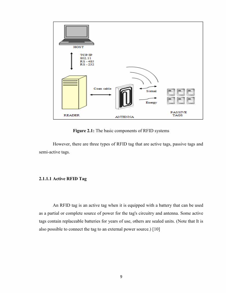
has the following main components and figure 2.1 was shows the basic components of
RFID systems and concepts.
RFID Tag / Transponder
RFID Reader
RFID Antenna
PC /Database
9
Figure 2.1: The basic components of RFID systems
However, there are three types of RFID tag that are active tags, passive tags and
semi-active tags.
2.1.1.1 Active RFID Tag
An RFID tag is an active tag when it is equipped with a battery that can be used
as a partial or complete source of power for the tag's circuitry and antenna. Some active
tags contain replaceable batteries for years of use, others are sealed units. (Note that It is
also possible to connect the tag to an external power source.) [10]

10
The major advantages of an active RFID tag are:
It can be read at distances of one hundred feet or more, greatly improving the
utility of the device
It may have other sensors that can use electricity for power.
The problems and disadvantages of an active RFID tag are:
The tag cannot function without battery power, which limits the lifetime of the
tag.
The tag is typically more expensive, often costing $20 or more each
The tag is physically larger, which may limit applications.
The long-term maintenance costs for an active RFID tag can be greater than
those of a passive tag if the batteries are replaced.
Battery outages in an active tag can result in expensive misreads.
Active RFID tags may have all or some of the following features:
longest communication range of any tag
the capability to perform independent monitoring and control
the capability of initiating communications
the capability of performing diagnostics
the highest data bandwidth
active RFID tags may even be equipped with autonomous networking, the tags
autonomously determine the best communication path.

11
2.1.1.2 Passive RFID Tag
A passive tag is an RFID tag that does not contain a battery, the power is
supplied by the reader. When radio waves from the reader are encountered by a passive
RFID tag, the coiled antenna within the tag forms a magnetic field. The tag draws power
from it, energizing the circuits in the tag. The tag then sends the information encoded in
the tag's memory. [10]
The major disadvantages of a passive RFID tag are:
The tag can be read only at very short distances, typically a few feet at most.
This greatly limits the device for certain applications.
It may not be possible to include sensors that can use electricity for power.
The tag remains readable for a very long time, even after the product to which
the tag is attached has been sold and is no longer being tracked. [10]
The advantages of a passive tag are:
The tag functions without a battery, these tags have a useful life of twenty years
or more.
The tag is typically much less expensive to manufacture
The tag is much smaller (some tags are the size of a grain of rice). These tags
have almost unlimited applications in consumer goods and other areas.

12
2.1.1.3 Semi-Active RFID Tag
Semi-active tag is a similar tag to active tags that have their own power supply
such as battery. The difference is the tag uses battery power only to switch on the
microchip circuit inside and not to transmit the signal wave to the reader. Radio waves
frequency is emitted as a passive tag with reflect the transmitted wave that was sent from
reader.
2.1.1.4 RFID Reader
An RFID reader is a device that is used to interrogate an RFID tag. The reader
has an antenna that emits radio waves; the tag responds by sending back its data. A
number of factors can affect the distance at which a tag can be read (the read range). The
frequency used for identification, the antenna gain, the orientation and polarization of
the reader antenna and the transponder antenna, as well as the placement of the tag on
the object to be identified will all have an impact on the RFID system’s read range.[10]
13
2.1.1.5 RFID Antenna
Generally, the antenna has been designed and is available in various forms but
serve to obtain data from individuals or objects that pass through the antenna. When the
inclusion of RFID tags print antenna, the tag was will be able to mark the activation of
the antenna and microchip that will generate accumulated in the tag. The next process
happens is that it will send information to the microchip was generated by printing
antennas. This means that there are interactions between the tag and antenna.
2.2 Web-based Laboratory Equipment Monitoring (WEM) System
RFID system is good for monitoring purpose. In supports of solving problem
identified and discussed in the previous chapter, this journal by Mohd Helmy A. Wahab
[1] from UTHM intends to implement RFID technology to monitor the laboratory
equipments which is named Web-based Laboratory Equipment Monitoring (WEM)
System. The main aim of his study is to design the WEM and apply the system in each
laboratory room to monitor in-out equipment flow and immediately update through web-
based environment.
This project enables the authorized personnel to monitor in or out equipment in
real time to replace the manual logging system. So, to overcome this problem the RFID
is selected where it has been widely utilized by many sectors to increase management
efficiency by reducing time and effort. WEM is divided into 2 components which are
software and hardware. In hardware component there are 5 others components which are
RFID tag (transponder), RFID reader (interrogator), personal computer, RS232 cable
and LAN hub. And for the software part there are 2 components which are database
design and web design. The master server contains the database which is used to store
all data collected from RFID reader where user can read or change all information in the

14
database. The RFID tags contain antennas to enable the receiving and transferring data
.The passive RFID tag creates power from magnetic field and uses it to energize the
circuits of the RFID chip and sends information back to the reader in the form of radio-
frequency waves.
WEM interface system developed by using visual basic 6.0 software. There is
also the floor plan for WEM system where RFID reader is place at the entrance door in
the laboratory and there is a server room to monitor all of the laboratory equipments.
[11]

15
Figure 2.2 Architecture of WEM system
Figure 2.3 WEM System Hardware Proposed floor plan

16
2.3 RFID development
RFID system had been used and commercialized starting from 1980’s. This
system had been used worldwide in many applications such as television, radio, radar
and many more. The advantage of using RFID is that it does not require direct contact or
line of sight scanning. According to the journal from Hazrullizam b Idris[12] about his
research of development of tracking system using RFID, an RFID system consists of
three components, antenna and transceiver which often combined into one reader and
transponder that usually the tag. The antenna use RF waves to transmit the signal to
activate the transponder. When activated, the transponders transmit data back to the
antenna. The data is to notified a programmable logic controller that an action should
occur the action could be as simple as raising an access gate or as complicated as
interfacing the database to carry out a monetary transaction.
There are two types of RFID which is active RFID and passive RFID. Active
RFID are used on large asset such as cargo container, rail cars and large reusable
container which need to be tracked over a long distance. They usually read distance from
60-100 meters. There are two types of active tags, transponder and beacon. For the
passive RFID tags, there no power source and no transmitter there cheaper than active
tags and no require maintenance. They have much shorter read range under 30 feet. An
RFID tags is a device that can be store and transmit data to the reader in contactless
manner using radio waves. RFID reader also known as interrogator is a device that can
read from and write data to compatible RFID tags. The component that consists in RFID
reader is transmitter, receiver, microprocessor, memory, controller, communication
interface and power.
The preceding subsections mentioned the advantages and characteristics of
RFID, but RFID cannot be well used in all applicable areas. Studies of barcode history
showed that it took approximately 25 years from the development of the first barcode by
the Drexel Institute of Technology in Philadelphia in 1949 to the first commercial


![Identifikasi Mineral Optik (Nikol Sejajar dan Silang) [Compatibility Mode].pdf](https://img.pdfslide.us/doc/110x75/563db932550346aa9a9afbd7/identifikasi-mineral-optik-nikol-sejajar-dan-silang-compatibility-modepdf.jpg)

