Embed Size (px)
Citation preview

1
UNIVERSITY OF PUNE
LAB COURSE I SYSTEM PROGRAMMING
AND OPERATING SYSTEM
(CS-331)
T.Y.B.SC.(COMPUTER SCIENCE) SEMESTER I
2
ADVISORS: PROF. A. G. GANGARDE (CHAIRMAN, BOS-COMP. SC.) CHAIRMAN: MRS. CHITRA NAGARKAR CO-ORDINATOR: PROF. MRS. MANISHA BHARAMBE AUTHORS:
Ms. Sampada vaishampayan Mr. Srikant Korke Ms. Swati joshi Ms. Seema Purandare Ms. Rekha joshi
BOARD OF STUDY (COMPUTER SCIENCE) MEMBERS:
1. MR. M. N. SHELAR 2. DR.VILAS KHARAT 3. MR. S. N. SHINDE 4. MR. U. S. SURVE 5. MR. V. R. WANI 6. MR. S. S. DESHMUKH 7. MR. PRASHANT MULE

3
ABOUT THE WORK BOOK OBJECTIVES OF THIS BOOK THIS WORKBOOK IS INTENDED TO BE USED BY T.Y.B.SC(COMPUTER SCIENCE) STUDENTS FOR THE THREE COMPUTER SCIENCE LABORATORY COURSES. THE OBJECTIVES OF THIS BOOK ARE 1. THE SCOPE OF THE COURSE. 2. BRINGING UNIFORMITY IN THE WAY COURSE IS CONDUCTED ACROSS DIFFERENT COLLEGES. 3. CONTINUOUS ASSESSMENT OF THE STUDENTS. 4. PROVIDING READY REFERENCES FOR STUDENTS WHILE WORKING IN THE LAB. HOW TO USE THIS BOOK? THIS BOOK IS MANDATORY FOR THE COMPLETION OF THE LABORATORY COURSE. IT IS A MEASURE OF THE PERFORMANCE OF THE STUDENT IN THE LABORATORY FOR THE ENTIRE DURATION OF THE COURSE. INSTRUCTIONS TO THE STUDENTS 1) STUDENTS SHOULD CARRY THIS BOOK DURING PRACTICAL SESSIONS OF COMPUTER SCIENCE. 2) STUDENTS SHOULD MAINTAIN SEPARATE JOURNAL FOR THE SOURCE CODE AND OUTPUTS. 3) STUDENT SHOULD READ THE TOPICS MENTIONED IN READING SECTION OF THIS BOOK BEFORE COMING FOR PRACTICAL. 4) STUDENTS SHOULD SOLVE ONLY THOSE EXERCISES WHICH ARE SELECTED BY PRACTICAL IN-CHARGE AS A PART OF JOURNAL ACTIVITY. HOWEVER, STUDENTS ARE FREE TO SOLVE ADDITIONAL EXERCISES TO DO MORE PRACTICE FOR THEIR PRACTICAL EXAMINATION. EXERCISE SET DIFFICULTY LEVEL RULE SELF ACTIVITY NA STUDENT SHOULD SOLVE THESE EXERCISES FOR PRACTICE ONLY. SET A EASY ALL EXERCISES ARE COMPULSORY. SET B MEDIUM AT LEAST ONE EXERCISE IS MANDATORY. SET C DIFFICULT NOT COMPULSORY. 5) STUDENTS WILL BE ASSESSED FOR EACH EXERCISE ON A SCALE OF 5 1.NOT DONE 0 2. INCOMPLETE 1 3.LATE COMPLETE 2 4.NEEDS IMPROVEMENT 3 5.COMPLETE 4 6.WELLDONE 5 INSTRUCTIONS TO THE PRACTICAL IN-CHARGE 1) EXPLAIN THE ASSIGNMENT AND RELATED CONCEPTS IN AROUND TEN MINUTES USING WHITE BOARD IF REQUIRED OR BY DEMONSTRATING THE SOFTWARE. 2) CHOOSE APPROPRIATE PROBLEMS TO BE SOLVED BY STUDENT. 3) AFTER A STUDENT COMPLETES A SPECIFIC SET, THE INSTRUCTOR HAS TO VERIFY THE OUTPUTS AND SIGN IN THE PROVIDED SPACE AFTER THE ACTIVITY.

4
4) ENSURE THAT THE STUDENTS USE GOOD PROGRAMMING PRACTICES. 5) YOU SHOULD EVALUATE EACH ASSIGNMENT CARRIED OUT BY A STUDENT ON A SCALE OF 5 AS SPECIFIED ABOVE TICKING APPROPRIATE BOX. 6) THE VALUE SHOULD ALSO BE ENTERED ON ASSIGNMENT COMPLETION PAGE OF RESPECTED LAB COURSE.
Assignment Number: 1 Title: Line Editor
Ready Reference:
A line editor is a text editor computer program that manipulates text primarily by the display, modification, and movement of lines.

5
Line editors are limited to primitive text-oriented input and output methods. Most edits are a line-at-a-time. Typing, editing, and document display do not occur simultaneously. Typically, typing does not enter text directly into the document. Instead, users modify the document text by entering terse commands on a text-only terminal. Commands and text, and corresponding output from the editor, will scroll up from the bottom of the screen in the order that they are entered or printed to the screen. Although the commands typically indicate the line(s) they modify, displaying the edited text within the context of larger portions of the document requires a separate command.
Command Meaning a To append p To display p m n To display range of lines p m – n To display previous n lines from mth position s Save d n To delete nth line d m n To delete range of lines f <pat> To search pattern i n To insert after nth line m n1 n2 To move line n1 at n2 position m n1 n2 n3 To move range of lines at n3 c n1 n2 To copy line n1 at position n2 c n1 n2 n3 To copy range of lines at n3 h To give help information about all commands Algorithm : The name of the file to be edited is to be taken as a command line argument. Open a empty file if no argument is supplied. Declare a node structure containing a character array to hold a line and two pointers. One pointing to previous node and one to next node ( Implement the line editor using doubly linklist.) Write separate functions for each of the above operations. Your program should display a prompt to accept the command. Operation : 1. a : ( To append) Accept the line from the user. Using the pointers move to the end of the list

6
Create a new node and write the line in it Append the new node at the end of the present
linked list
2. p : ( To print or display) : Go to the starting of the linked list Print the contents of each node Traverse to the end of the linked list 3. p m n ( To display a range of lines) : Accept m and n from the user Traverse from the starting of the linked list to the mth node Starting from the mth node, print the contents of
the next n nodes.
4. p m - n ( To display previous n lines) : Accept m and n from the user Traverse from the starting of the linked list to the mth node using the previous pointer of each node,
traverse backward, and print the contents of the previous n nodes
5. s ( Save) : Accept file name from user Create a new file with that name Traverse the link list and write the contents of
each node to the file
6. d n : Accept n from the user Traverse the linked list from beginning to
n-1th position. Change the next pointer of n-1 th node to point to n +1 th node, and the previous pointer of n + 1 th node to point to n – 1 th node Delete the nth node
7. d m n : Accept m and n from the user Traverse the linked list from beginning to
m-1th position. Take another pointer and make it traverse n nodes from the mth node. Change the next pointer of m-1 th node to point to the next node after n nodes, and the previous pointer of this next node to point to the m – 1 th node Delete all the node in between

7
8. f <pat> : Accept the pattern from the user Traverse the linked list from beginning to end and for each node where the pattern is found,
print the node no. 9. i n : Accept the new line and n from the user Traverse the linked list from first position to
nth position Create a new node to hold the new line Insert this node after the nth node
10. m n1 n2 : Accept n1 and n2 from the user Take two pointers and traverse the linked list
so that one pointer is at n1th node and second pointer is at n2th node. Change the previous and next pointers so that the n1th node is moved after the n2th node.
11. m n1 n2 n3 : Accept n1, n2 and n3 from the user Take three pointers and traverse the linked list
so that one pointer is at n1th node, second pointer is at n2th node, and the third pointer is at the n3rd node Change the previous and next pointers so that the nodes from n1 to n2 are moved after the n3rd node.
12. c n1 n2 : Accept n1 and n2 from the user Take two pointers and traverse the linked list
so that one pointer is at n1th node and second pointer is at n2th node. Create a new node and copy the contents of the n1 th node to the new node Append this new node after the n2th node.
13. c n1 n2 n3 : Accept n1, n2 and n3 from the user Take three pointers and traverse the linked list
so that one pointer is at n1th node, second pointer is at n2th node, and the third pointer is at the n3rd node Make as many new nodes as required ad copy the lines from n1 to n2 into these new nodes Insert these new nodes after the n3rd node.
14. h : Display help for all the commands.

8
Set A
1) Write a command line program for line editor. The file to be editied is taken as command line argument; an empty file is opened for editing if no argument is supplied. It should display a ‘$’ prompt to accept the line editing commands. Implement the following commands:
i. a ii. d n
iii. d m n iv. s
2) Write a command line program for line editor. The file to be edited is taken as
command line argument; an empty file is opened for editing if no argument is supplied. It should display a ‘$’ prompt to accept the line editing commands. Implement the following commands:
i. a ii. p
iii. p m n iv. i n
Set B
1) Write a command line program for line editor. The file to be edited is taken as command line argument; an empty file is opened for editing if no argument is supplied. It should display a ‘$’ prompt to accept the line editing commands. Implement the following commands:
i. a ii. p
iii. m n1 n2 iv. m n1 n2 n3
3) Write a command line program for line editor. The file to be edited is taken as
command line argument; an empty file is opened for editing if no argument is supplied. It should display a ‘$’ prompt to accept the line editing commands. Implement the following commands:
i. a ii. s
iii. c n1 n2 iv. c n1 n2 n3
Set C
1) Write a command line program for line editor. The file to be edited is taken as command line argument; an empty file is opened for editing if no argument is supplied. It should display a ‘$’ prompt to accept the line editing commands. Implement the following commands:

9
i. a ii. p m – n
iii. f <pat> iv. h
Assignment Evaluation 0:Not Done [ ] 1:Incomplete [ ] 2.Late Complete [ ] 3:Needs Improvement [ ] 4:Complete [ ] 5:WellDone [ ] Signature of the Instructor Date of Completion ______________________________________________________ Assignment Number : 2 Title : Simulator Ready reference : Hypothetical Machine:
• Not Real Machine but used to illustrate features of machine language and techniques used in assembler.
• The Addresses From 0,1,2,3,… and these addresses are accessible to programmers.
• The machine has six condition codes from 0 to 5 • This machine can not handle string data.
Simulator:
• Simulator is the program which can execute machine program of hypothetical machine and produce result.
• The software which gives fill of the things which not really exist is called as simulator.
Need Of simulator:
• Using simulator less time is required for debugging of simple programs. • It is easier for programmer to explain complex problems if you have a simulator. • It is easier to discover if a problem is in the hardware or software when you use a
simulator. • The simulator requires no setup time. • One of the primary advantages of simulators is that they are able to provide users
with practical feedback when designing real world systems. Instruction Set : Opcode Mnemonic Format 01 ADD [Label] ADD op1 op2
10
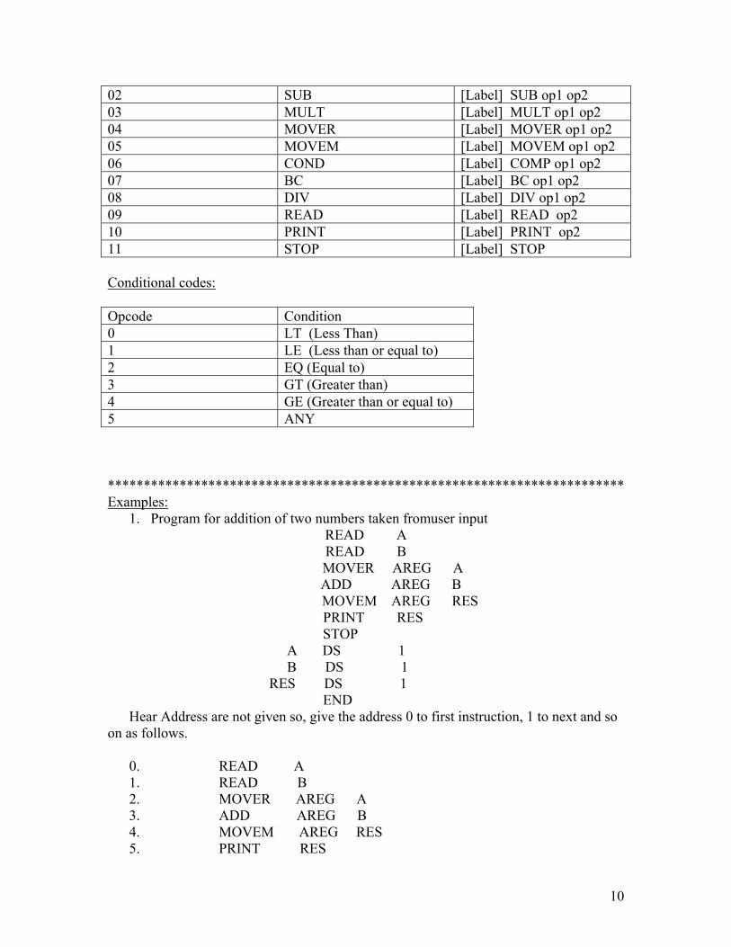
02 SUB [Label] SUB op1 op2 03 MULT [Label] MULT op1 op2 04 MOVER [Label] MOVER op1 op2 05 MOVEM [Label] MOVEM op1 op2 06 COND [Label] COMP op1 op2 07 BC [Label] BC op1 op2 08 DIV [Label] DIV op1 op2 09 READ [Label] READ op2 10 PRINT [Label] PRINT op2 11 STOP [Label] STOP Conditional codes: Opcode Condition 0 LT (Less Than) 1 LE (Less than or equal to) 2 EQ (Equal to) 3 GT (Greater than) 4 GE (Greater than or equal to) 5 ANY ************************************************************************ Examples:
1. Program for addition of two numbers taken fromuser input READ A READ B
MOVER AREG A ADD AREG B
MOVEM AREG RES PRINT RES
STOP A DS 1 B DS 1 RES DS 1 END Hear Address are not given so, give the address 0 to first instruction, 1 to next and so on as follows.
0. READ A 1. READ B 2. MOVER AREG A 3. ADD AREG B 4. MOVEM AREG RES 5. PRINT RES
11
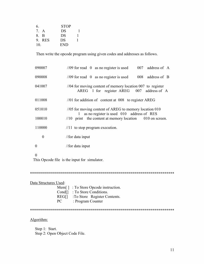
6. STOP 7. A DS 1 8. B DS 1 9. RES DS 1 10. END Then write the opcode program using given codes and addresses as follows.
090007 //09 for read 0 as no register is used 007 address of A 090008 //09 for read 0 as no register is used 008 address of B 041007 //04 for moving content of memory location 007 to register AREG 1 for register AREG 007 address of A 011008 //01 for addition of content at 008 to register AREG 051010 //05 for moving content of AREG to memory location 010 1 as no register is used 010 address of RES 100010 //10 print the content at memory location 010 on screen. 110000 //11 to stop program execution. 0 //for data input 0 //for data input 0 This Opcode file is the input for simulator. ************************************************************************ Data Structures Used: Mem[ ] : To Store Opcode instruction. Cond[] : To Store Conditions. REG[] :To Store Register Contents. PC : Program Counter ************************************************************************ Algorithm: Step 1: Start. Step 2: Open Object Code File.

12
Step 3: Read All File and Store All Instructions in Mem[] Array. Step 4: Close Object File. Step 5: PC=0. Step 6: Separate Instruction, operand 1,operand 2 from each instruction whose address is PC. Step 7: If Instruction is 1: REG[operand1-1] + = Mem[operand2] GOTO step 8 2: REG[operand1-1] - = Mem[operand2] GOTO step 8 3: REG[operand 1-1] * = Mem[operand2] GOTO step 8 4: REG[operand1-1] = Mem[operand2] GOTO step 8 5: Mem[operand2] = REG[operand1-1] GOTO step 8 6: If REG[operand1-1] < Mem[operand2] then Cond[0] = 1 else Cond[0]=0 If REG[operand1-1] < = Mem[operand2] then Cond[1] = 1 else Cond[1]=0 If REG[operand1-1] = = Mem[operand2] then Cond[2] = 1 else Cond[2]=0 If REG[operand1-1] > Mem[operand2] then Cond[3] = 1 else Cond[3]=0 If REG[operand1-1] > = Mem[operand2] then Cond[4] = 1 else Cond[4]=0 GOTO step 8. 7: If Cond[operand1-1] = = 1 then PC=operand2 then goto Step 6. Else GOTO Step 8. 8: REG[operand1-1]/=Mem[operand2] GOTO Step 8. 9: Accept Mem[operand2] GOTO Step 8. 10:Print Mem[operand2] GOTO Step 8. 11:GOTO Step 9. Step 8: PC++ GOTO step 6.
13
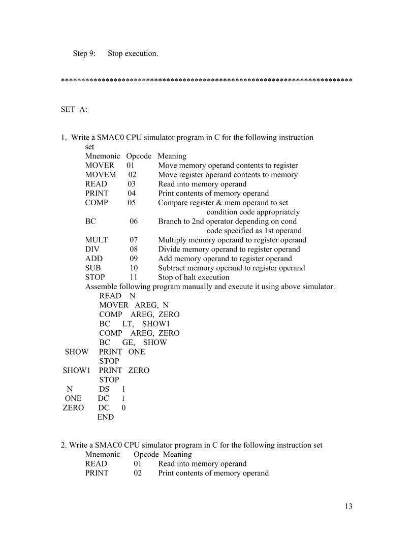
Step 9: Stop execution. ************************************************************************ SET A: 1. Write a SMAC0 CPU simulator program in C for the following instruction set Mnemonic Opcode Meaning MOVER 01 Move memory operand contents to register MOVEM 02 Move register operand contents to memory READ 03 Read into memory operand PRINT 04 Print contents of memory operand COMP 05 Compare register & mem operand to set condition code appropriately BC 06 Branch to 2nd operator depending on cond code specified as 1st operand MULT 07 Multiply memory operand to register operand DIV 08 Divide memory operand to register operand ADD 09 Add memory operand to register operand SUB 10 Subtract memory operand to register operand STOP 11 Stop of halt execution Assemble following program manually and execute it using above simulator. READ N MOVER AREG, N COMP AREG, ZERO BC LT, SHOW1 COMP AREG, ZERO BC GE, SHOW SHOW PRINT ONE STOP SHOW1 PRINT ZERO STOP N DS 1 ONE DC 1 ZERO DC 0 END 2. Write a SMAC0 CPU simulator program in C for the following instruction set Mnemonic Opcode Meaning READ 01 Read into memory operand PRINT 02 Print contents of memory operand

14
STOP 03 Stop of halt execution ADD 04 Add memory operand to register operand SUB 05 Subtract memory operand to register operand MOVER 06 Move memory operand contents to register MOVEM 07 Move register operand contents to memory MULT 08 Multiply memory operand to register operand DIV 09 Divide memory operand to register operand BC 10 Branch to 2nd operator depending on cond code specified as 1st operand COMP 11 Compare register & mem operand to set condition code appropriately Assemble following program manually and execute it using above simulator. READ N LOOP MOVER AREG, SUM ADD AREG, N MOVEM AREG, SUM MOVER AREG, N SUB AREG, ONE COMP AREG, ZERO BC LE, OUT MOVEM AREG, N BC ANY, LOOP OUT PRINT SUM STOP N DS 1 ZERO DC 0 ONE DC 1 SUM DC 0 END 3: Write a SMAC0 CPU simulator program in C for the following instruction set Mnemonic Opcode Meaning STOP 01 Stop of halt execution SUB 02 Subtract memory operand to register operand ADD 03 Add memory operand to register operand DIV 04 Divide memory operand to register operand MULT 05 Multiply memory operand to register operand PRINT 06 Print contents of memory operand READ 07 Read into memory operand MOVEM 08 Move register operand contents to memory MOVER 09 Move memory operand contents to register BC 10 Branch to 2nd operator depending on cond code specified as 1st operand COMP 11 Compare register & mem operand to set condition code appropriately Assemble following program manualy and execute it using above simulator.
15
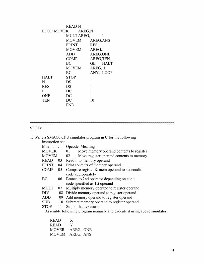
READ N LOOP MOVER AREG, N MULT AREG, I MOVEM AREG, ANS PRINT RES MOVEM AREG, I ADD AREG, ONE COMP AREG, TEN BC GE, HALT MOVEM AREG, I BC ANY, LOOP HALT STOP N DS 1 RES DS 1 I DC 1 ONE DC 1 TEN DC 10 END ************************************************************************ SET B: 1: Write a SMAC0 CPU simulator program in C for the following instruction set Mnemonic Opcode Meaning MOVER 01 Move memory operand contents to register MOVEM 02 Move register operand contents to memory READ 03 Read into memory operand PRINT 04 Print contents of memory operand COMP 05 Compare register & mem operand to set condition code appropriately BC 06 Branch to 2nd operator depending on cond code specified as 1st operand MULT 07 Multiply memory operand to register operand DIV 08 Divide memory operand to register operand ADD 09 Add memory operand to register operand SUB 10 Subtract memory operand to register operand STOP 11 Stop of halt execution Assemble following program manualy and execute it using above simulator. READ X
READ Y MOVER AREG, ONE MOVEM AREG, ANS
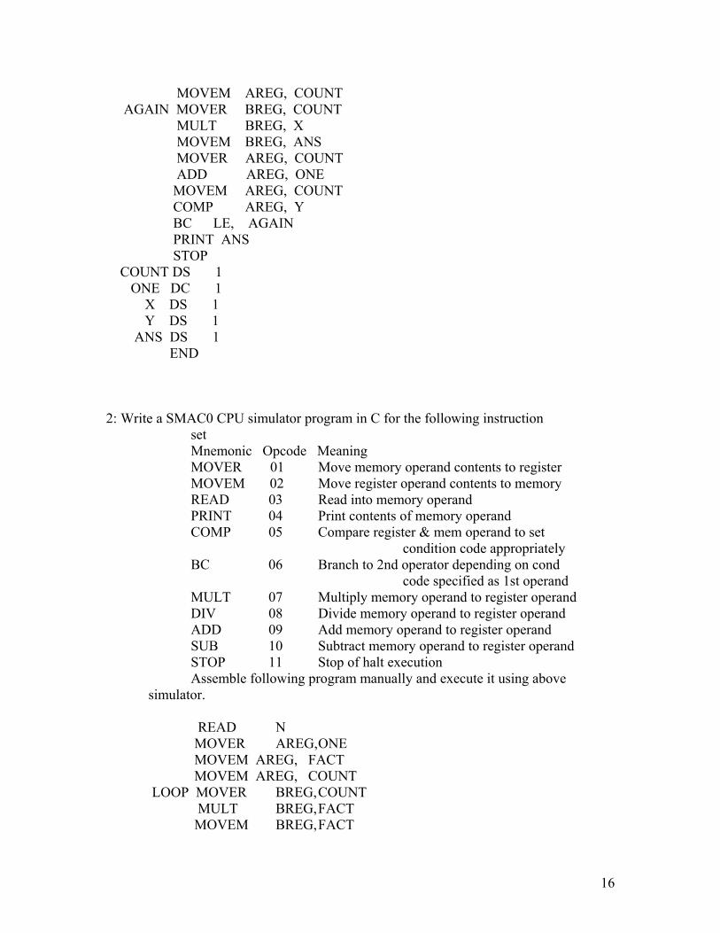
16
MOVEM AREG, COUNT AGAIN MOVER BREG, COUNT
MULT BREG, X MOVEM BREG, ANS MOVER AREG, COUNT ADD AREG, ONE MOVEM AREG, COUNT COMP AREG, Y BC LE, AGAIN PRINT ANS STOP
COUNT DS 1 ONE DC 1 X DS 1 Y DS 1 ANS DS 1
END
2: Write a SMAC0 CPU simulator program in C for the following instruction
set Mnemonic Opcode Meaning MOVER 01 Move memory operand contents to register MOVEM 02 Move register operand contents to memory READ 03 Read into memory operand PRINT 04 Print contents of memory operand COMP 05 Compare register & mem operand to set condition code appropriately BC 06 Branch to 2nd operator depending on cond code specified as 1st operand MULT 07 Multiply memory operand to register operand DIV 08 Divide memory operand to register operand ADD 09 Add memory operand to register operand SUB 10 Subtract memory operand to register operand STOP 11 Stop of halt execution Assemble following program manually and execute it using above simulator. READ N MOVER AREG, ONE MOVEM AREG, FACT MOVEM AREG, COUNT LOOP MOVER BREG, COUNT MULT BREG, FACT MOVEM BREG, FACT

17
MOVER AREG, COUNT ADD AREG, ONE MOVEM AREG, COUNT COMP AREG, N BC LE, LOOP PRINT FACT STOP
COUNT DS 1 ONE DC 1
N DS 1 FACT DS 1 END ******************************************************************
SET C:
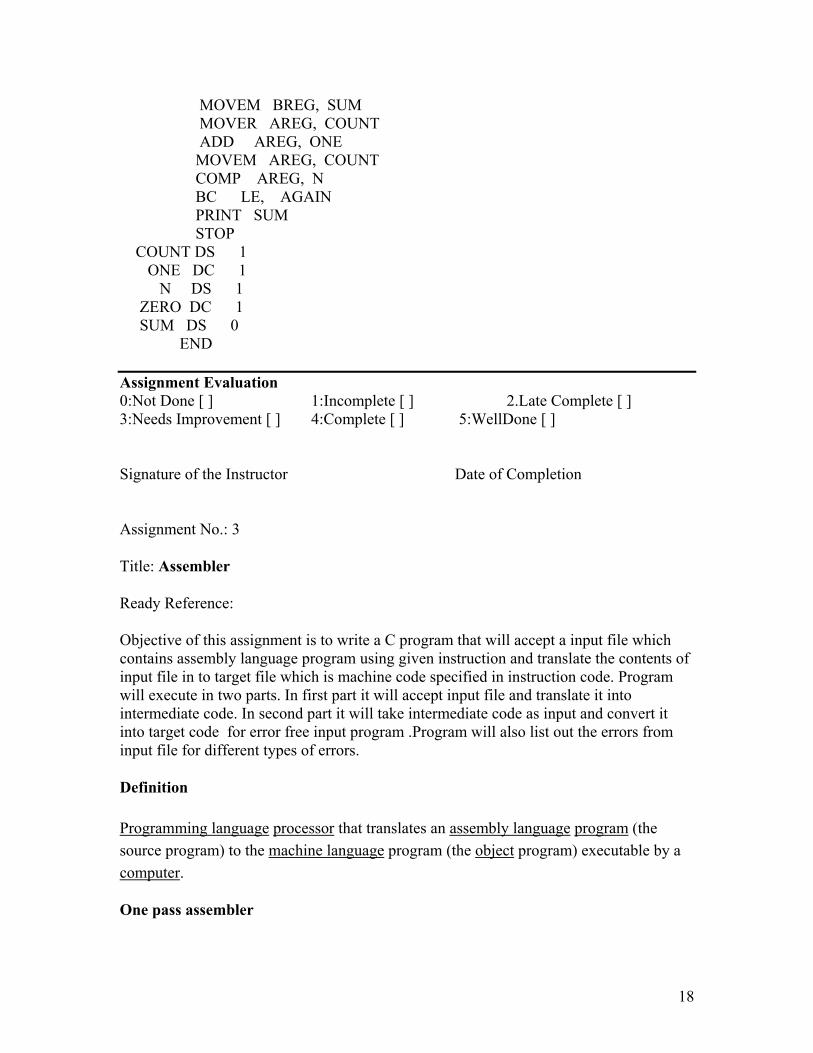
1:Write a SMAC0 CPU simulator program in C for the following instruction set Mnemonic Opcode Meaning MOVER 01 Move memory operand contents to register MOVEM 02 Move register operand contents to memory READ 03 Read into memory operand PRINT 04 Print contents of memory operand COMP 05 Compare register & mem operand to set condition code appropriately BC 06 Branch to 2nd operator depending on cond code specified as 1st operand MULT 07 Multiply memory operand to register operand DIV 08 Divide memory operand to register operand ADD 09 Add memory operand to register operand SUB 10 Subtract memory operand to register operand STOP 11 Stop of halt execution Assemble following program manually and execute it using above
simulator. READ N MOVER AREG, ZERO MOVEM AREG, SUM MOVEM AREG, COUNT
AGAIN MOVER BREG, SUM ADD BREG, COUNT
18
MOVEM BREG, SUM MOVER AREG, COUNT ADD AREG, ONE MOVEM AREG, COUNT COMP AREG, N BC LE, AGAIN PRINT SUM STOP
COUNT DS 1 ONE DC 1 N DS 1 ZERO DC 1 SUM DS 0 END Assignment Evaluation 0:Not Done [ ] 1:Incomplete [ ] 2.Late Complete [ ] 3:Needs Improvement [ ] 4:Complete [ ] 5:WellDone [ ] Signature of the Instructor Date of Completion Assignment No.: 3
Title: Assembler
Ready Reference:
Objective of this assignment is to write a C program that will accept a input file which contains assembly language program using given instruction and translate the contents of input file in to target file which is machine code specified in instruction code. Program will execute in two parts. In first part it will accept input file and translate it into intermediate code. In second part it will take intermediate code as input and convert it into target code for error free input program .Program will also list out the errors from input file for different types of errors.
Definition
Programming language processor that translates an assembly language program (the source program) to the machine language program (the object program) executable by a computer.
One pass assembler
19
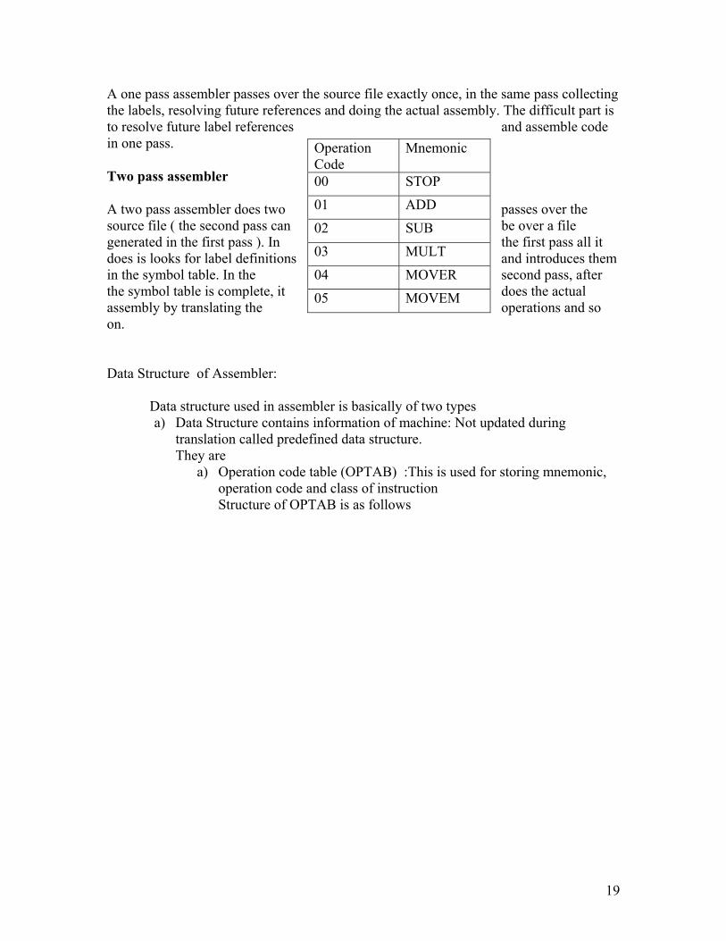
A one pass assembler passes over the source file exactly once, in the same pass collecting the labels, resolving future references and doing the actual assembly. The difficult part is to resolve future label references and assemble code in one pass.
Two pass assembler
A two pass assembler does two passes over the source file ( the second pass can be over a file generated in the first pass ). In the first pass all it does is looks for label definitions and introduces them in the symbol table. In the second pass, after the symbol table is complete, it does the actual assembly by translating the operations and so on.
Data Structure of Assembler: Data structure used in assembler is basically of two types
a) Data Structure contains information of machine: Not updated during translation called predefined data structure. They are
a) Operation code table (OPTAB) :This is used for storing mnemonic, operation code and class of instruction Structure of OPTAB is as follows
Operation Code
Mnemonic
00 STOP 01 ADD 02 SUB 03 MULT 04 MOVER 05 MOVEM
20
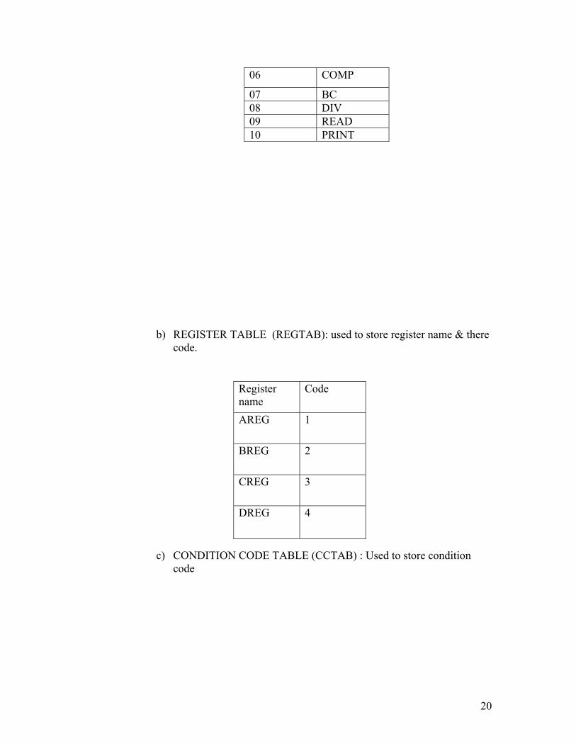
b) REGISTER TABLE (REGTAB): used to store register name & there
code.
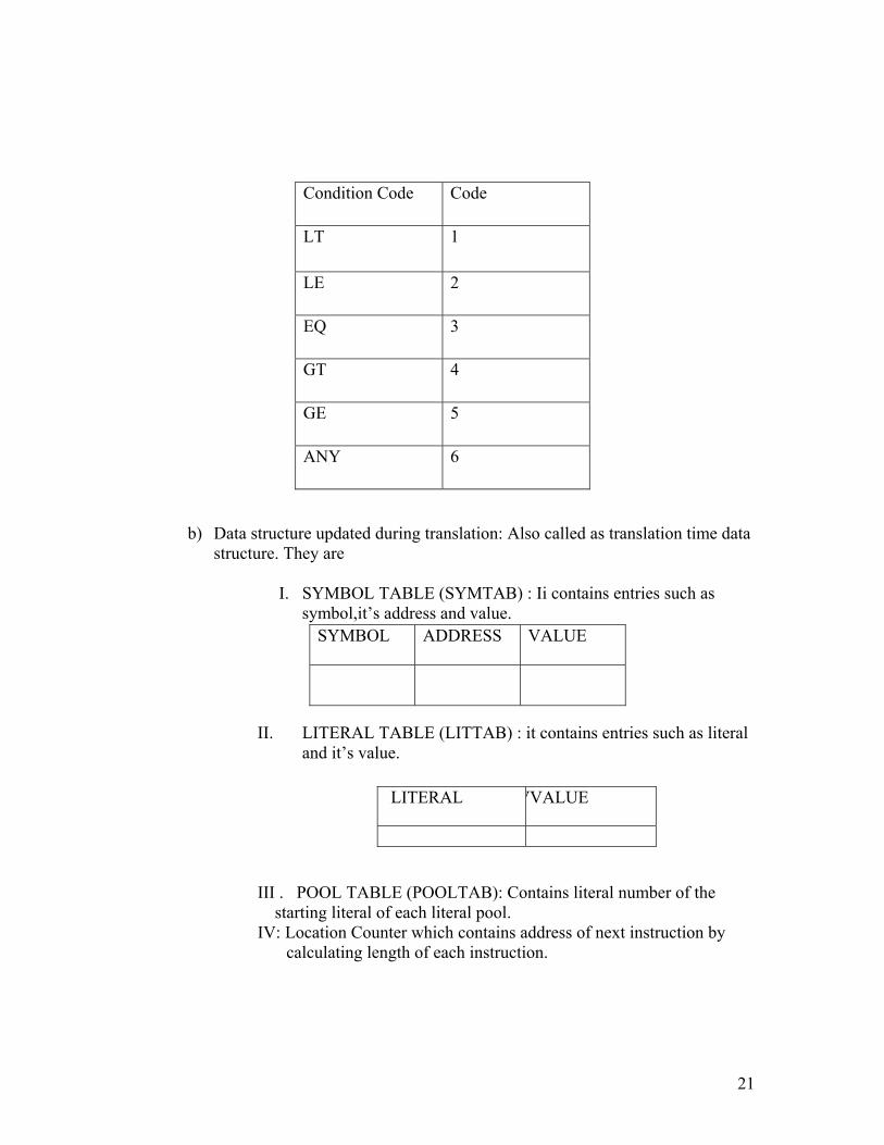
c) CONDITION CODE TABLE (CCTAB) : Used to store condition code
06 COMP
07 BC 08 DIV 09 READ 10 PRINT
Register name
Code
AREG 1
BREG 2
CREG 3
DREG 4
21
b) Data structure updated during translation: Also called as translation time data structure. They are
I. SYMBOL TABLE (SYMTAB) : Ii contains entries such as
symbol,it’s address and value.
II. LITERAL TABLE (LITTAB) : it contains entries such as literal and it’s value.
III . POOL TABLE (POOLTAB): Contains literal number of the starting literal of each literal pool. IV: Location Counter which contains address of next instruction by
calculating length of each instruction.
Condition Code Code
LT 1
LE 2
EQ 3
GT 4
GE 5
ANY 6
SYMBOL ADDRESS VALUE
LITERAL VVALUE

22
ALGORITHM PASS 1
• Initialize location counter, entries of all tables as zero. • Read statements from input file one by one. • While next statement is not END statement
I. Tokenize or separate out input statement as label,numonic,operand1,operand2
II. If label is present insert label into symbol table. III. If the statement is LTORG statement processes it by
making it’s entry into literal table, pool table and allocate memory.
IV. If statement is START or ORIGEN Process location counter accordingly.
V. If an EQU statement, assign value to symbol by correcting entry in symbol table.
VI. For declarative statement update code, size and location counter.
VII. Generate intermediate code. VIII. Pass this intermediate code to pass -2.
PASS -2
1. Initialize memory, table entries, and location counter.
2. While next statement is not END
a) If statement is LTORG statement then process literal ie assemble literal into machine code.
b) For START/ORIGIN statement process location counter.
c) For declarative statements assemble constants into machine code.
d) For imperative statements get operand address from symbol table or literal table and assemble it to machine code.
e) If the instruction is in OPTAB get appropriate opcode into intermediate code.
f) Move the contents to target code. g) Print output file.
SET A Q1. Write a program to accept a program written in assembly language. After accepting entire program list out errors wherever applicable. a) Symbols used but not defined b) Symbols declared but not used

23
c) Redeclaration of symbols Consider following program as input START 100 READ X Y MOVER BREG, X ADD BREG, X X MOVEM AREG, Z STOP X DS 1 Y DS 1 END Q2. Write a program to accept a program written in assembly language. After accepting entire program list out errors wherever applicable. a) Invalid statement b) Invalid mnemonic Consider following program as input START 100 ,2 READ A MOVER A,AREG BDD AREG, A A MOVEM AREG, ‘=2’ STOP X DS 1 Y DS 1 END Q3. Write a program to accept a program written in assembly language. After accepting entire program list out errors wherever applicable.
a) Symbols used but not defined b) Symbols declared but not used c) Redeclaration of symbols
d)Invalid symbol name Consider following program as input START 100 READ A MOVER AREG, ORIGIN ADD AREG, A A MOVEM AREG, C STOP

24
X DS 1 Y DS 1 END Q4. Write a c program that will read given assembly language program as input. Display the contents of SYMBOL TABLE, LITERAL TABLE and POOL TABLE. Consider following program as input. START 100
MOVER AREG, =5 MOVER BREG, =1 MOVER BREG, A
LTORG MOVER CREG, =4 MOVER DREG, =1 MOVER BREG, B PRINT A STOP
A DS 1 B DC 2
END SET B: Q1 Write a assembler for error free assembly language program that will generate target code. Display the contents of symbol table. Also display target code generated. Consider following program READ N LOOP MOVER AREG, SUM ADD AREG N MOVEM AREG SUM MOVER AREG N SUB AREG, ONE COMP AREG ZERO BC LE OUT MOVEM AREG N BC ANY LOOP OUT PRINT SUM STOP N DS 1 ZERO DC ‘0’ ONE DC ‘1’ SUM DC ‘0’ END Q 2 : Write a assembler for error free assembly language program that will generate
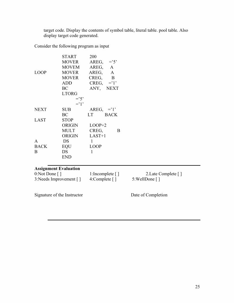
25
target code. Display the contents of symbol table, literal table. pool table. Also display target code generated. Consider the following program as input
START 200 MOVER AREG, =’5’ MOVEM AREG, A
LOOP MOVER AREG, A MOVER CREG, B ADD CREG, =’1’ BC ANY, NEXT LTORG
=’5’ =’1’ NEXT SUB AREG, =’1’
BC LT BACK LAST STOP
ORIGIN LOOP+2 MULT CREG, B ORIGIN LAST+1
A DS 1 BACK EQU LOOP B DS 1
END
Assignment Evaluation 0:Not Done [ ] 1:Incomplete [ ] 2.Late Complete [ ] 3:Needs Improvement [ ] 4:Complete [ ] 5:WellDone [ ] Signature of the Instructor Date of Completion

26
Assignment Number:- 4 Title: Macro Preprocessor Ready Reference: Topic:
Macro is a facility for extending the set of operations provided in an assembly language through incorporation of new operations desired by a programmer. A macro definition is enclosed between MACRO and MEND keywords. Eg. MACRO Macro header statement. INCR &X, &Y, ®=AREG Macro prototype statement MOVER ®, &X Model statements ADD ®, &Y MOVEM ®, &X MEND End of definition unit
Parameters used in the prototype statement are formal parameters, starting with special character &. When certain formal parameters have default values, it can be specified using ‘=’ sign and are called as keyword parameters. Formal parameters without default values are called as positional parameters. Macro Preprocessor is a program that take an assembly language program (source program) with macro definition and macro calls as input and generates an assembly program without any macro definitions and calls (i.e. it should perform macro expansion) as an output. Eg. i) INCR P,Q A macro calls ii) INCR P,Q, ®= BREG The Macro Preprocessor will expand the macro call as follows:
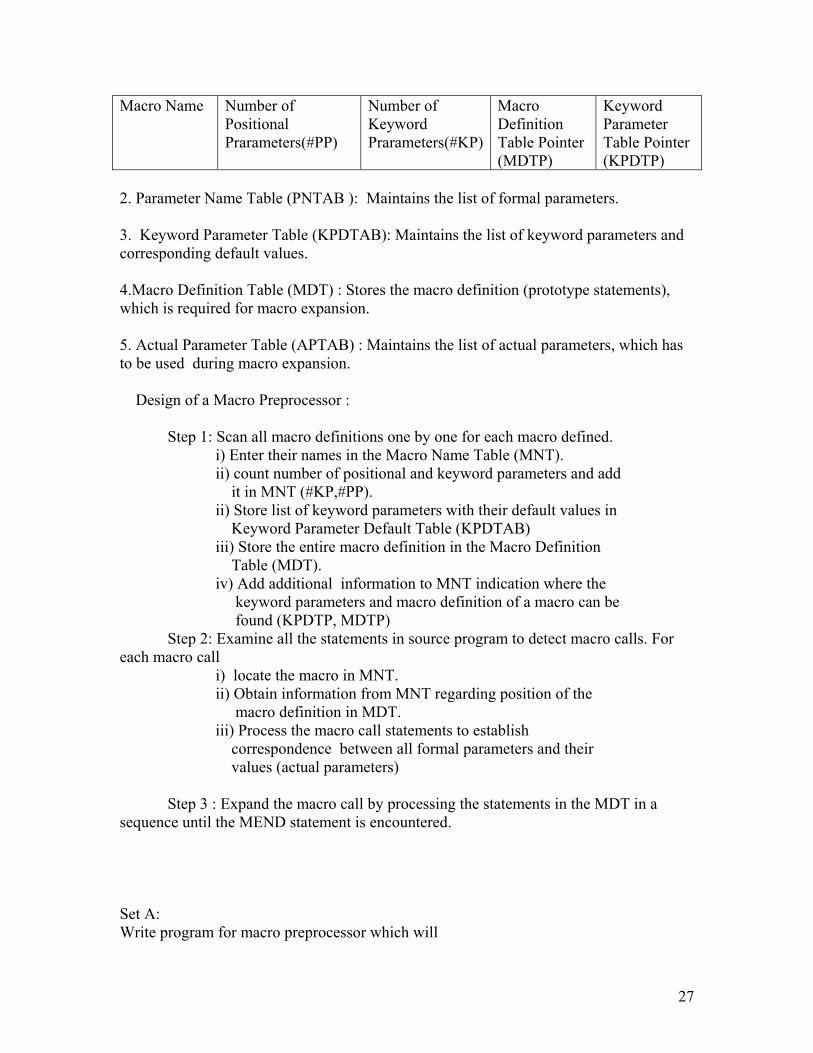
i) MOVER AREG, P ADD AREG, Q MOVEM AREG, P ii) MOVER BREG, P ADD BREG, Q MOVEM BREG, P Data structures used by Macro Preporcessor: 1. Macro Name Table (MNT) : Maintains following details
27
Macro Name Number of Positional Prarameters(#PP)
Number of Keyword Prarameters(#KP)
Macro Definition Table Pointer (MDTP)
Keyword Parameter Table Pointer (KPDTP)
2. Parameter Name Table (PNTAB ): Maintains the list of formal parameters. 3. Keyword Parameter Table (KPDTAB): Maintains the list of keyword parameters and corresponding default values. 4.Macro Definition Table (MDT) : Stores the macro definition (prototype statements), which is required for macro expansion. 5. Actual Parameter Table (APTAB) : Maintains the list of actual parameters, which has to be used during macro expansion. Design of a Macro Preprocessor : Step 1: Scan all macro definitions one by one for each macro defined. i) Enter their names in the Macro Name Table (MNT). ii) count number of positional and keyword parameters and add it in MNT (#KP,#PP). ii) Store list of keyword parameters with their default values in Keyword Parameter Default Table (KPDTAB) iii) Store the entire macro definition in the Macro Definition Table (MDT). iv) Add additional information to MNT indication where the keyword parameters and macro definition of a macro can be found (KPDTP, MDTP) Step 2: Examine all the statements in source program to detect macro calls. For each macro call i) locate the macro in MNT. ii) Obtain information from MNT regarding position of the macro definition in MDT. iii) Process the macro call statements to establish correspondence between all formal parameters and their values (actual parameters) Step 3 : Expand the macro call by processing the statements in the MDT in a sequence until the MEND statement is encountered. Set A: Write program for macro preprocessor which will
28
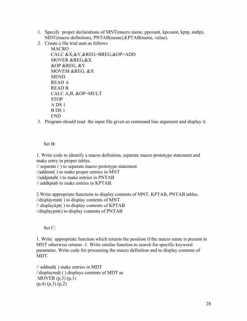
1. Specify proper declarations of MNT(macro name, ppcount, kpcount, kptp, mdtp), MDT(macro definition), PNTAB(name),KPTAB(name, value).
2. Create a file trial.asm as follows MACRO CALC &X,&Y,®=BREG,&OP=ADD MOVER ®,&X &OP ®, &Y MOVEM ®, &X MEND READ A READ B CALC A,B, &OP=MULT STOP A DS 1 B DS 1 END
3. Program should read the input file given as command line argument and display it.
Set B:
1. Write code to identify a macro definition, separate macro prototype statement and make entry in proper tables. // separate ( ) to separate macro prototype statement //addmnt( ) to make proper entries in MNT //addpntab( ) to make entries in PNTAB // addkptab to make entries in KPTAB. 2.Write appropriate functions to display contents of MNT, KPTAB, PNTAB tables. //displaymnt( ) to display contents of MNT // displaykpt( ) to display contents of KPTAB //displaypnt() to display contents of PNTAB
Set C:
1. Write appropriate function which returns the position if the macro name is present in MNT otherwise returns -1. Write similar function to search for specific keyword parameter. Write code for processing the macro definition and to display contents of MDT. // addmdt( ) make entries in MDT //displaymdt ( ) displays contents of MDT as MOVER (p,3) (p,1) (p,4) (p,3) (p,2)
29
: : MEND
2. Write function expand( ) to expand the macro call by building appropriate APL. Display the assembly language program with expanded macro calls and show the contents of all data structures. Assignment Evaluation 0:Not Done [ ] 1:Incomplete [ ] 2.Late Complete [ ] 3:Needs Improvement [ ] 4:Complete [ ] 5:WellDone [ ] Signature of the Instructor Date of Completion
Assignment Number:- 5 Title: DFA -driver Ready Reference: Topic:
A finite state machine (FSM) or finite automaton (plural: automata), is a model of behavior composed of a finite number of states, transitions between those states, and actions.
It is similar to a "flow graph" where we can inspect the way in which the logic runs when certain conditions are met.
A finite state machine is an abstract model of a machine with a primitive (sometimes read-only) internal memory.
In the theory of computation, a deterministic finite automaton (DFA)—is a finite state machine, where for each pair of state and input symbol; there is one and only one transition to a next state.
DFAs recognize the set of regular languages, and no other languages.
30
A DFA will take in, a string of input symbols. For each input symbol, it will then transit to a state, given by, following a transition function. When the last input symbol has been received, it will either accept or reject the string, depending on whether the DFA is in an accepting state or a non-accepting state.
Introduction
A finite state machine (fsm) or finite automaton (plural: automata), is a model of behavior composed of a finite number of states, transitions between those states, and actions.
It is similar to a "flow graph" where we can inspect the way in which the logic runs when certain conditions are met.
A finite state machine is an abstract model of a machine with a primitive (sometimes read-only) internal memory.
In the theory of computation, a deterministic finite automaton (DFA)—is a finite state machine, where for each pair of state and input symbol; there is one and only one transition to a next state.
DFA’s recognize the set of regular languages, and no other languages.
A DFA will take in, a string of input symbols. For each input symbol, it will then transit to a state, given by, following a transition function. When the last input symbol has been received, it will either accept or reject the string, depending on whether the DFA is in an accepting state or a non-accepting state.
Formal definition A DFA is a 5-tuple , (q, Σ, δ, q0, f), consisting of • A finite set of states (q) • A finite set of input symbols called the alphabet (Σ) • A transition function (δ : q × Σ → q) • A start state (q0 ) • A set of accept states (f ⊆ q)
Working
Let m be a DFA such that m = (q, Σ, δ, q0, f), and x = x0x1 ... Xn−1 be a string over the alphabet Σ. M accepts the string x if a sequence of states, r0,r1, ..., rn, exists in q with the following conditions:
1. r0 = q0 2. ri+1 = δ(ri, xi), for i = 0, ..., n−1
31
3. rn ∈ f.
In words,
• The first condition says that the machine starts in the start state q0. • The second condition says that given each character of string x, the machine will
transit from state to state, according to the transition function δ. • The last condition says that, the machine accepts x if the last input of x causes the
machine to halt in one of the accepting states. Otherwise, it is said that the automaton rejects the string.
The set of strings, the DFA accepts form a language, which is the language the DFA, recognizes.
Example
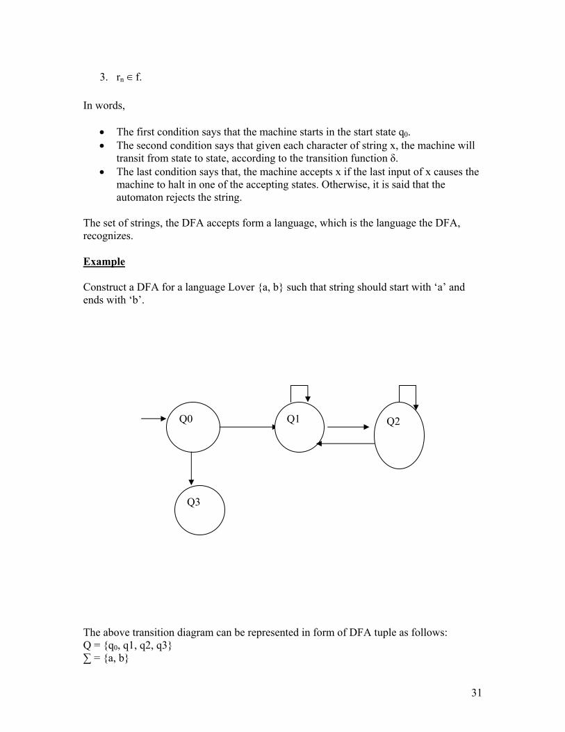
Construct a DFA for a language Lover {a, b} such that string should start with ‘a’ and ends with ‘b’.
The above transition diagram can be represented in form of DFA tuple as follows: Q = {q0, q1, q2, q3} ∑ = {a, b}
Q0 Q1 Q2
Q3
32
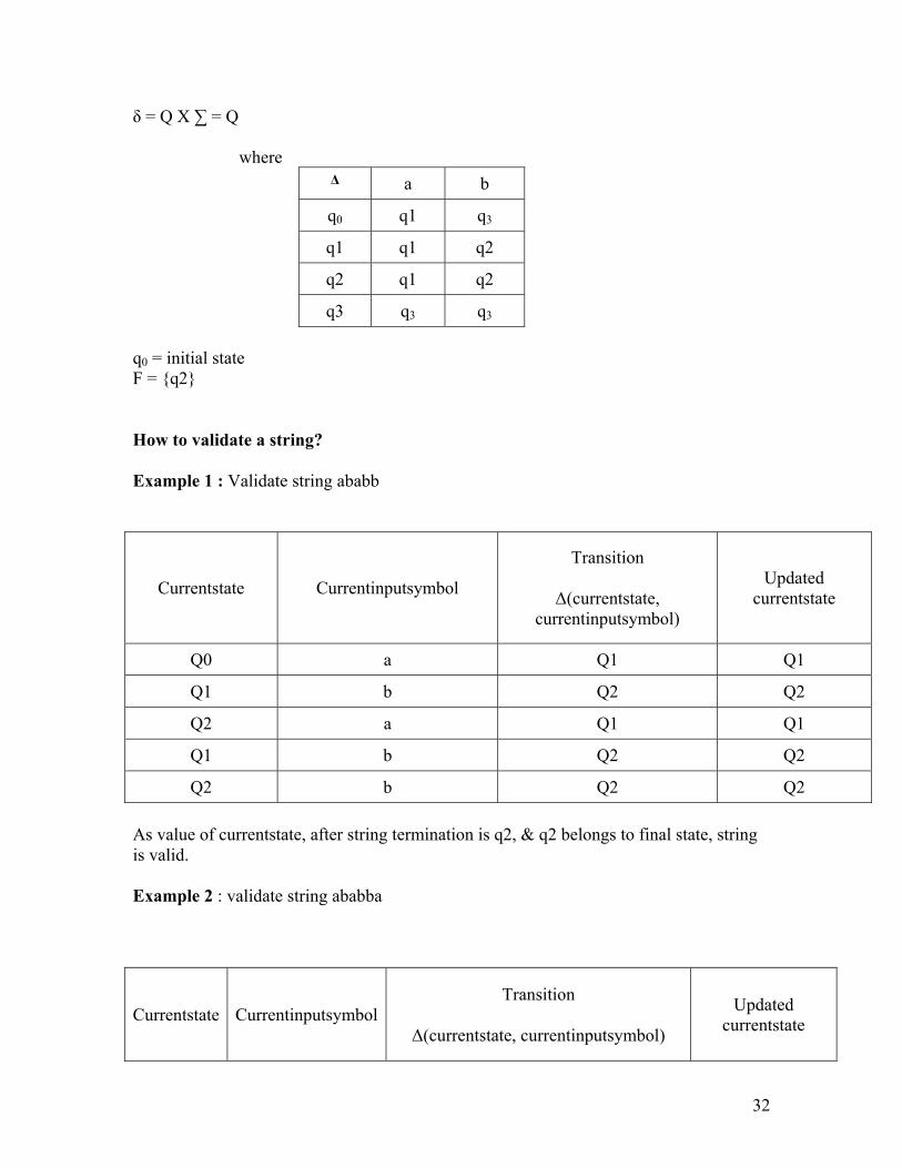
δ = Q X ∑ = Q where
Δ a b
q0 q1 q3
q1 q1 q2
q2 q1 q2
q3 q3 q3 q0 = initial state F = {q2}
How to validate a string?
Example 1 : Validate string ababb
Currentstate Currentinputsymbol
Transition
Δ(currentstate, currentinputsymbol)
Updated currentstate
Q0 a Q1 Q1
Q1 b Q2 Q2
Q2 a Q1 Q1
Q1 b Q2 Q2
Q2 b Q2 Q2
As value of currentstate, after string termination is q2, & q2 belongs to final state, string is valid.
Example 2 : validate string ababba
Currentstate CurrentinputsymbolTransition
Δ(currentstate, currentinputsymbol)
Updated currentstate

33
Q0 a Q1 Q1
Q1 b Q2 Q2
Q2 a Q1 Q1
Q1 b Q2 Q2
Q2 b Q2 Q2
Q2 a Q1 Q1
As value of currentstate, after string termination is q1, & q1 does not belong to final state, string is invalid.
Algorithm to implement DFA driver :
Input :
1. Number of states 2. Number of input symbols 3. Character array to store input symbols 4. Initial state 5. Number of final states 6. Array to store final states 7. 2 dimensional array transition (with dimension number of states x input symbols)
to store states 8. Teststring to be validated
Output: DFA always give boolean output : yes, if string is acceted by DFA, no otherwise
Procedure :
1. Accept all the required input data 2. Let currentstate = initialstate 3. Traverse the entire string by scanning one character at a time. 4. Update currentstate by finding transition of current character of teststring from
currentstate. 5. Repeat step 4 till the end of the string. 6. Lastly, if currentstate belongs to array of final states, string is valid, else invalid.
Set a :
1. Implement DFA driver for following languages :

34
(a) L = { set of all strings over {0, 1, 2} which start with 0 and contains substring 102 }
(b) L = { set of all strings over {x, y, z} which start with xy, end with zz and does not contain substring zxx }
(c) L = { set of all strings over {0, 1} which contain even number of 0’s and odd number of 1’s }
Set b:
1. Implement DFA driver with all validation checks.
Assignment Evaluation 0:Not Done [ ] 1:Incomplete [ ] 2.Late Complete [ ] 3:Needs Improvement [ ] 4:Complete [ ] 5:WellDone [ ] Signature of the Instructor Date of Completion