Embed Size (px)
Citation preview
© 2013 Cisco and/or its affiliates. All rights reserved. This document is Cisco Public. Page 1 of 29
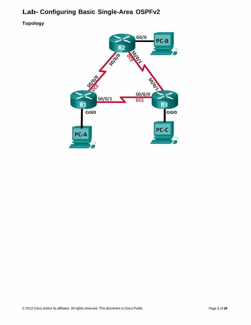
Lab- Configuring Basic Single-Area OSPFv2
Topology
G0/0 G0/0
© 2013 Cisco and/or its affiliates. All rights reserved. This document is Cisco Public. Page 2 of 29
Lab - Configuring Basic Single-Area OSPFv2
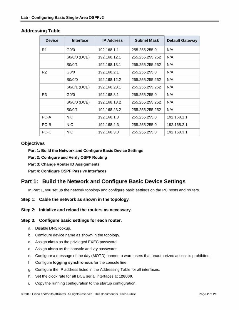
Addressing Table
Device
Interface
IP Address
Subnet Mask
Default Gateway
R1 G0/0 192.168.1.1 255.255.255.0 N/A
S0/0/0 (DCE) 192.168.12.1 255.255.255.252 N/A
S0/0/1 192.168.13.1 255.255.255.252 N/A
R2 G0/0 192.168.2.1 255.255.255.0 N/A
S0/0/0 192.168.12.2 255.255.255.252 N/A
S0/0/1 (DCE) 192.168.23.1 255.255.255.252 N/A
R3 G0/0 192.168.3.1 255.255.255.0 N/A
S0/0/0 (DCE) 192.168.13.2 255.255.255.252 N/A
S0/0/1 192.168.23.2 255.255.255.252 N/A
PC-A NIC 192.168.1.3 255.255.255.0 192.168.1.1
PC-B NIC 192.168.2.3 255.255.255.0 192.168.2.1
PC-C NIC 192.168.3.3 255.255.255.0 192.168.3.1
Objectives
Part 1: Build the Network and Configure Basic Device Settings
Part 2: Configure and Verify OSPF Routing
Part 3: Change Router ID Assignments
Part 4: Configure OSPF Passive Interfaces
Part 1: Build the Network and Configure Basic Device Settings
In Part 1, you set up the network topology and configure basic settings on the PC hosts and routers.
Step 1: Cable the network as shown in the topology.
Step 2: Initialize and reload the routers as necessary.
Step 3: Configure basic settings for each router.
a. Disable DNS lookup.
b. Configure device name as shown in the topology.
c. Assign class as the privileged EXEC password.
d. Assign cisco as the console and vty passwords.
e. Configure a message of the day (MOTD) banner to warn users that unauthorized access is prohibited.
f. Configure logging synchronous for the console line.
g. Configure the IP address listed in the Addressing Table for all interfaces.
h. Set the clock rate for all DCE serial interfaces at 128000.
i. Copy the running configuration to the startup configuration.
© 2013 Cisco and/or its affiliates. All rights reserved. This document is Cisco Public. Page 3 of 29
Lab - Configuring Basic Single-Area OSPFv2
Step 4: Configure PC hosts.
Step 5: Test connectivity.
The routers should be able to ping one another, and each PC should be able to ping its default gateway. The PCs are unable to ping other PCs until OSPF routing is configured. Verify and troubleshoot if necessary.
Part 2: Configure and Verify OSPF Routing
In Part 2, you will configure OSPFv2 routing on all routers in the network and then verify that routing tables are updated correctly. After OSPF has been verified, you will configure OSPF authentication on the links for added security.
Step 1: Configure OSPF on R1.
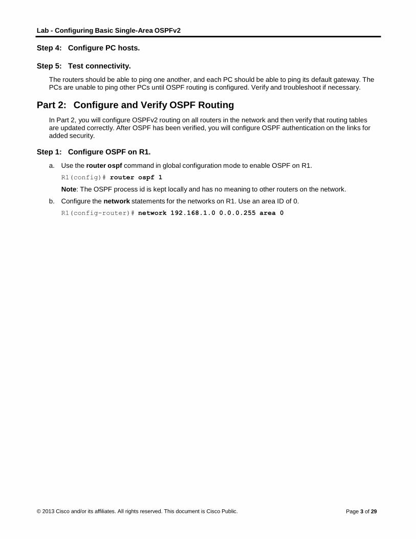
a. Use the router ospf command in global configuration mode to enable OSPF on R1.
R1(config)# router ospf 1
Note: The OSPF process id is kept locally and has no meaning to other routers on the network.
b. Configure the network statements for the networks on R1. Use an area ID of 0.
R1(config-router)# network 192.168.1.0 0.0.0.255 area 0
© 2013 Cisco and/or its affiliates. All rights reserved. This document is Cisco Public. Page 4 of 29
Lab - Configuring Basic Single-Area OSPFv2
R1(config-router)# network 192.168.12.0 0.0.0.3 area 0
R1(config-router)# network 192.168.13.0 0.0.0.3 area 0
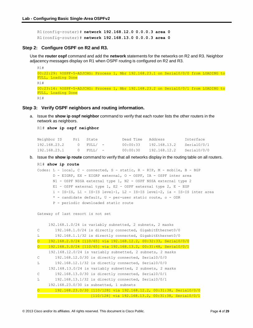
Step 2: Configure OSPF on R2 and R3.
Use the router ospf command and add the network statements for the networks on R2 and R3. Neighbor
adjacency messages display on R1 when OSPF routing is configured on R2 and R3.
R1#
00:22:29: %OSPF-5-ADJCHG: Process 1, Nbr 192.168.23.1 on Serial0/0/0 from LOADING to
FULL, Loading Done
R1#
00:23:14: %OSPF-5-ADJCHG: Process 1, Nbr 192.168.23.2 on Serial0/0/1 from LOADING to
FULL, Loading Done
R1#
Step 3: Verify OSPF neighbors and routing information.
a. Issue the show ip ospf neighbor command to verify that each router lists the other routers in the network as neighbors.
R1# show ip ospf neighbor
Neighbor ID Pri State Dead Time Address Interface 192.168.23.2 0 FULL/ - 00:00:33 192.168.13.2 Serial0/0/1 192.168.23.1 0 FULL/ - 00:00:30 192.168.12.2 Serial0/0/0
b. Issue the show ip route command to verify that all networks display in the routing table on all routers.
R1# show ip route
Codes: L - local, C - connected, S - static, R - RIP, M - mobile, B - BGP
D - EIGRP, EX - EIGRP external, O - OSPF, IA - OSPF inter area
N1 - OSPF NSSA external type 1, N2 - OSPF NSSA external type 2
E1 - OSPF external type 1, E2 - OSPF external type 2, E - EGP
i - IS-IS, L1 - IS-IS level-1, L2 - IS-IS level-2, ia - IS-IS inter area
* - candidate default, U - per-user static route, o - ODR
P - periodic downloaded static route
Gateway of last resort is not set
192.168.1.0/24 is variably subnetted, 2 subnets, 2 masks
C 192.168.1.0/24 is directly connected, GigabitEthernet0/0
L 192.168.1.1/32 is directly connected, GigabitEthernet0/0
O 192.168.2.0/24 [110/65] via 192.168.12.2, 00:32:33, Serial0/0/0
O 192.168.3.0/24 [110/65] via 192.168.13.2, 00:31:48, Serial0/0/1
192.168.12.0/24 is variably subnetted, 2 subnets, 2 masks
C 192.168.12.0/30 is directly connected, Serial0/0/0
L 192.168.12.1/32 is directly connected, Serial0/0/0
192.168.13.0/24 is variably subnetted, 2 subnets, 2 masks
C 192.168.13.0/30 is directly connected, Serial0/0/1
L 192.168.13.1/32 is directly connected, Serial0/0/1
192.168.23.0/30 is subnetted, 1 subnets
O 192.168.23.0/30 [110/128] via 192.168.12.2, 00:31:38, Serial0/0/0
[110/128] via 192.168.13.2, 00:31:38, Serial0/0/1
© 2013 Cisco and/or its affiliates. All rights reserved. This document is Cisco Public. Page 5 of 29
Lab - Configuring Basic Single-Area OSPFv2
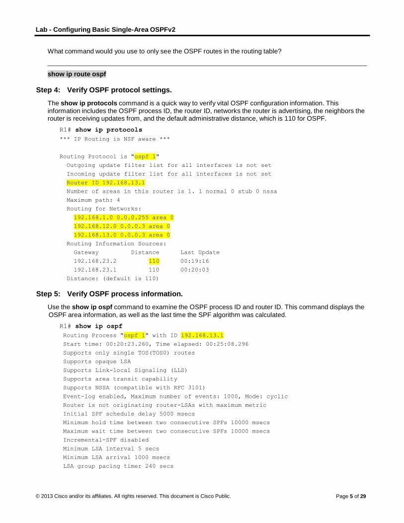
What command would you use to only see the OSPF routes in the routing table?
show ip route ospf
Step 4: Verify OSPF protocol settings.
The show ip protocols command is a quick way to verify vital OSPF configuration information. This information includes the OSPF process ID, the router ID, networks the router is advertising, the neighbors the router is receiving updates from, and the default administrative distance, which is 110 for OSPF.
R1# show ip protocols
*** IP Routing is NSF aware ***
Routing Protocol is "ospf 1"
Outgoing update filter list for all interfaces is not set
Incoming update filter list for all interfaces is not set
Router ID 192.168.13.1
Number of areas in this router is 1. 1 normal 0 stub 0 nssa
Maximum path: 4
Routing for Networks:
192.168.1.0 0.0.0.255 area 0
192.168.12.0 0.0.0.3 area 0
192.168.13.0 0.0.0.3 area 0
Routing Information Sources:
Gateway Distance Last Update
192.168.23.2 110 00:19:16
192.168.23.1 110 00:20:03
Distance: (default is 110)
Step 5: Verify OSPF process information.
Use the show ip ospf command to examine the OSPF process ID and router ID. This command displays the
OSPF area information, as well as the last time the SPF algorithm was calculated.
R1# show ip ospf
Routing Process "ospf 1" with ID 192.168.13.1
Start time: 00:20:23.260, Time elapsed: 00:25:08.296
Supports only single TOS(TOS0) routes
Supports opaque LSA
Supports Link-local Signaling (LLS)
Supports area transit capability
Supports NSSA (compatible with RFC 3101)
Event-log enabled, Maximum number of events: 1000, Mode: cyclic
Router is not originating router-LSAs with maximum metric
Initial SPF schedule delay 5000 msecs
Minimum hold time between two consecutive SPFs 10000 msecs
Maximum wait time between two consecutive SPFs 10000 msecs
Incremental-SPF disabled
Minimum LSA interval 5 secs
Minimum LSA arrival 1000 msecs
LSA group pacing timer 240 secs
© 2013 Cisco and/or its affiliates. All rights reserved. This document is Cisco Public. Page 6 of 29
Lab - Configuring Basic Single-Area OSPFv2
Interface flood pacing timer 33 msecs
Retransmission pacing timer 66 msecs
Number of external LSA 0. Checksum Sum 0x000000
Number of opaque AS LSA 0. Checksum Sum 0x000000
Number of DCbitless external and opaque AS LSA 0
Number of DoNotAge external and opaque AS LSA 0
Number of areas in this router is 1. 1 normal 0 stub 0 nssa
Number of areas transit capable is 0
External flood list length 0
IETF NSF helper support enabled
Cisco NSF helper support enabled
Reference bandwidth unit is 100 mbps
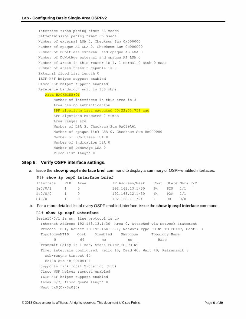
Area BACKBONE(0)
Number of interfaces in this area is 3
Area has no authentication
SPF algorithm last executed 00:22:53.756 ago
SPF algorithm executed 7 times
Area ranges are
Number of LSA 3. Checksum Sum 0x019A61
Number of opaque link LSA 0. Checksum Sum 0x000000
Number of DCbitless LSA 0
Number of indication LSA 0
Number of DoNotAge LSA 0
Flood list length 0
Step 6: Verify OSPF interface settings.
a. Issue the show ip ospf interface brief command to display a summary of OSPF-enabled interfaces.
R1# show ip ospf interface brief
Interface PID Area IP Address/Mask Cost State Nbrs F/C Se0/0/1 1 0 192.168.13.1/30 64 P2P 1/1 Se0/0/0 1 0 192.168.12.1/30 64 P2P 1/1 Gi0/0 1 0 192.168.1.1/24 1 DR 0/0
b. For a more detailed list of every OSPF-enabled interface, issue the show ip ospf interface command.
R1# show ip ospf interface
Serial0/0/1 is up, line protocol is up
Internet Address 192.168.13.1/30, Area 0, Attached via Network Statement
Process ID 1, Router ID 192.168.13.1, Network Type POINT_TO_POINT, Cost: 64
Topology-MTID Cost Disabled Shutdown Topology Name
0 64 no no Base
Transmit Delay is 1 sec, State POINT_TO_POINT
Timer intervals configured, Hello 10, Dead 40, Wait 40, Retransmit 5
oob-resync timeout 40
Hello due in 00:00:01
Supports Link-local Signaling (LLS)
Cisco NSF helper support enabled
IETF NSF helper support enabled
Index 3/3, flood queue length 0
Next 0x0(0)/0x0(0)
© 2013 Cisco and/or its affiliates. All rights reserved. This document is Cisco Public. Page 7 of 29
Lab - Configuring Basic Single-Area OSPFv2
Last flood scan length is 1, maximum is 1
Last flood scan time is 0 msec, maximum is 0 msec
Neighbor Count is 1, Adjacent neighbor count is 1
Adjacent with neighbor 192.168.23.2
Suppress hello for 0 neighbor(s)
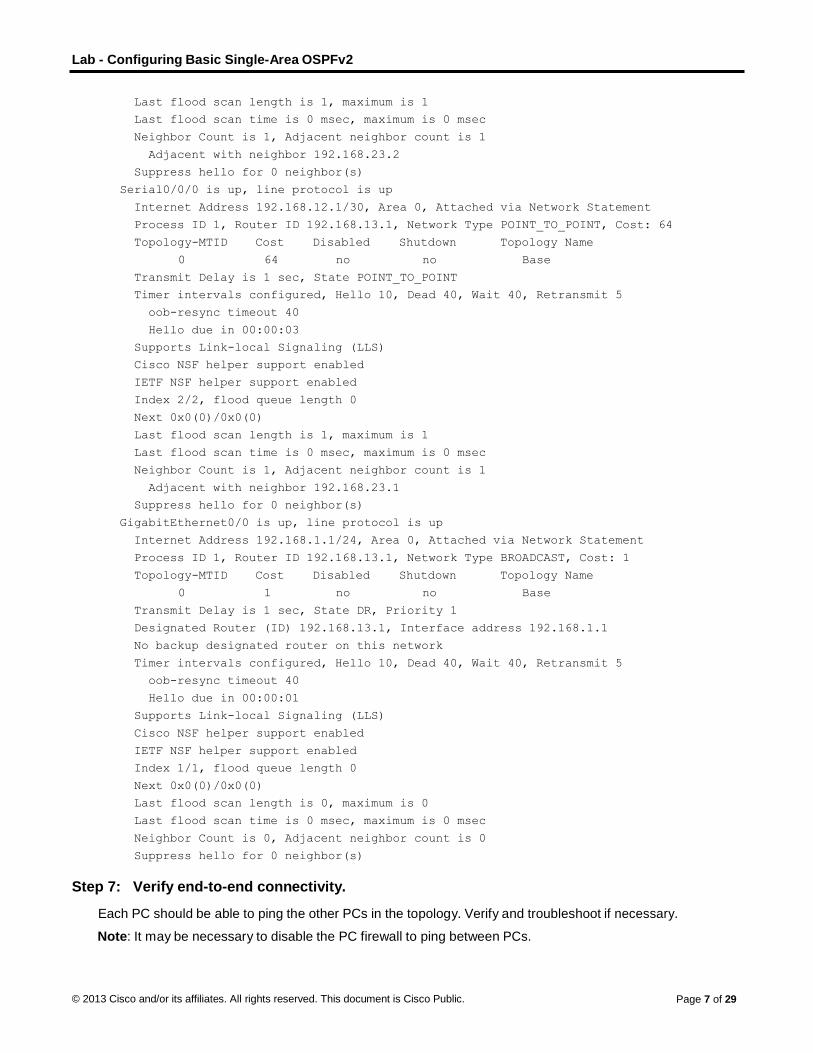
Serial0/0/0 is up, line protocol is up
Internet Address 192.168.12.1/30, Area 0, Attached via Network Statement
Process ID 1, Router ID 192.168.13.1, Network Type POINT_TO_POINT, Cost: 64
Topology-MTID Cost Disabled Shutdown Topology Name
0 64 no no Base
Transmit Delay is 1 sec, State POINT_TO_POINT
Timer intervals configured, Hello 10, Dead 40, Wait 40, Retransmit 5
oob-resync timeout 40
Hello due in 00:00:03
Supports Link-local Signaling (LLS)
Cisco NSF helper support enabled
IETF NSF helper support enabled
Index 2/2, flood queue length 0
Next 0x0(0)/0x0(0)
Last flood scan length is 1, maximum is 1
Last flood scan time is 0 msec, maximum is 0 msec
Neighbor Count is 1, Adjacent neighbor count is 1
Adjacent with neighbor 192.168.23.1
Suppress hello for 0 neighbor(s)
GigabitEthernet0/0 is up, line protocol is up
Internet Address 192.168.1.1/24, Area 0, Attached via Network Statement
Process ID 1, Router ID 192.168.13.1, Network Type BROADCAST, Cost: 1
Topology-MTID Cost Disabled Shutdown Topology Name
0 1 no no Base
Transmit Delay is 1 sec, State DR, Priority 1
Designated Router (ID) 192.168.13.1, Interface address 192.168.1.1
No backup designated router on this network
Timer intervals configured, Hello 10, Dead 40, Wait 40, Retransmit 5
oob-resync timeout 40
Hello due in 00:00:01
Supports Link-local Signaling (LLS)
Cisco NSF helper support enabled
IETF NSF helper support enabled
Index 1/1, flood queue length 0
Next 0x0(0)/0x0(0)
Last flood scan length is 0, maximum is 0
Last flood scan time is 0 msec, maximum is 0 msec
Neighbor Count is 0, Adjacent neighbor count is 0
Suppress hello for 0 neighbor(s)
Step 7: Verify end-to-end connectivity.
Each PC should be able to ping the other PCs in the topology. Verify and troubleshoot if necessary.
Note: It may be necessary to disable the PC firewall to ping between PCs.
© 2013 Cisco and/or its affiliates. All rights reserved. This document is Cisco Public. Page 8 of 29
Lab - Configuring Basic Single-Area OSPFv2
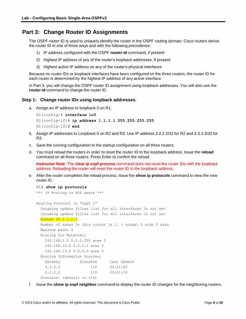
Part 3: Change Router ID Assignments
The OSPF router ID is used to uniquely identify the router in the OSPF routing domain. Cisco routers derive the router ID in one of three ways and with the following precedence:
1) IP address configured with the OSPF router-id command, if present
2) Highest IP address of any of the router’s loopback addresses, if present
3) Highest active IP address on any of the router’s physical interfaces
Because no router IDs or loopback interfaces have been configured on the three routers, the router ID for each router is determined by the highest IP address of any active interface.
In Part 3, you will change the OSPF router ID assignment using loopback addresses. You will also use the router-id command to change the router ID.
Step 1: Change router IDs using loopback addresses.
a. Assign an IP address to loopback 0 on R1.
R1(config)# interface lo0
R1(config-if)# ip address 1.1.1.1 255.255.255.255
R1(config-if)# end
b. Assign IP addresses to Loopback 0 on R2 and R3. Use IP address 2.2.2.2/32 for R2 and 3.3.3.3/32 for R3.
c. Save the running configuration to the startup configuration on all three routers.
d. You must reload the routers in order to reset the router ID to the loopback address. Issue the reload
command on all three routers. Press Enter to confirm the reload.
Instructor Note: The clear ip ospf process command does not reset the router IDs with the loopback
address. Reloading the router will reset the router ID to the loopback address.
e. After the router completes the reload process, issue the show ip protocols command to view the new
router ID.
R1# show ip protocols
*** IP Routing is NSF aware ***
Routing Protocol is "ospf 1"
Outgoing update filter list for all interfaces is not set
Incoming update filter list for all interfaces is not set
Router ID 1.1.1.1
Number of areas in this router is 1. 1 normal 0 stub 0 nssa
Maximum path: 4
Routing for Networks:
192.168.1.0 0.0.0.255 area 0
192.168.12.0 0.0.0.3 area 0
192.168.13.0 0.0.0.3 area 0
Routing Information Sources:
Gateway Distance Last Update
3.3.3.3 110 00:01:00
2.2.2.2 110 00:01:14
Distance: (default is 110)
f. Issue the show ip ospf neighbor command to display the router ID changes for the neighboring routers.
© 2013 Cisco and/or its affiliates. All rights reserved. This document is Cisco Public. Page 9 of 29
Lab - Configuring Basic Single-Area OSPFv2
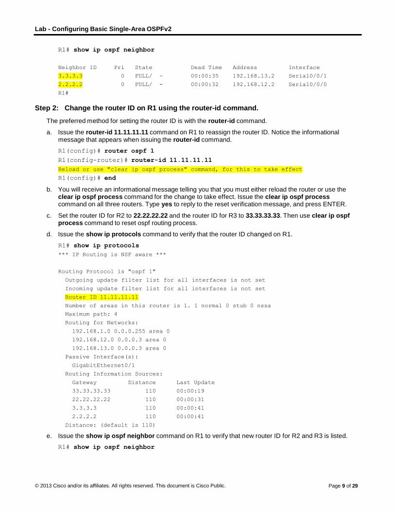
R1# show ip ospf neighbor
Neighbor ID Pri State Dead Time Address Interface 3.3.3.3 0 FULL/ - 00:00:35 192.168.13.2 Serial0/0/1 2.2.2.2 0 FULL/ - 00:00:32 192.168.12.2 Serial0/0/0 R1#
Step 2: Change the router ID on R1 using the router-id command.
The preferred method for setting the router ID is with the router-id command.
a. Issue the router-id 11.11.11.11 command on R1 to reassign the router ID. Notice the informational message that appears when issuing the router-id command.
R1(config)# router ospf 1
R1(config-router)# router-id 11.11.11.11
Reload or use "clear ip ospf process" command, for this to take effect
R1(config)# end
b. You will receive an informational message telling you that you must either reload the router or use the clear ip ospf process command for the change to take effect. Issue the clear ip ospf process command on all three routers. Type yes to reply to the reset verification message, and press ENTER.
c. Set the router ID for R2 to 22.22.22.22 and the router ID for R3 to 33.33.33.33. Then use clear ip ospf process command to reset ospf routing process.
d. Issue the show ip protocols command to verify that the router ID changed on R1.
R1# show ip protocols
*** IP Routing is NSF aware ***
Routing Protocol is "ospf 1"
Outgoing update filter list for all interfaces is not set
Incoming update filter list for all interfaces is not set
Router ID 11.11.11.11
Number of areas in this router is 1. 1 normal 0 stub 0 nssa
Maximum path: 4
Routing for Networks:
192.168.1.0 0.0.0.255 area 0
192.168.12.0 0.0.0.3 area 0
192.168.13.0 0.0.0.3 area 0
Passive Interface(s):
GigabitEthernet0/1
Routing Information Sources:
Gateway Distance Last Update
33.33.33.33 110 00:00:19
22.22.22.22 110 00:00:31
3.3.3.3 110 00:00:41
2.2.2.2 110 00:00:41
Distance: (default is 110)
e. Issue the show ip ospf neighbor command on R1 to verify that new router ID for R2 and R3 is listed.
R1# show ip ospf neighbor
© 2013 Cisco and/or its affiliates. All rights reserved. This document is Cisco Public. Page 10 of 29
Lab - Configuring Basic Single-Area OSPFv2
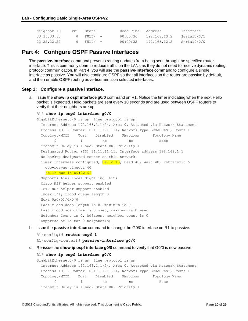
Neighbor ID Pri State Dead Time Address Interface 33.33.33.33 0 FULL/ - 00:00:36 192.168.13.2 Serial0/0/1 22.22.22.22 0 FULL/ - 00:00:32 192.168.12.2 Serial0/0/0
Part 4: Configure OSPF Passive Interfaces
The passive-interface command prevents routing updates from being sent through the specified router interface. This is commonly done to reduce traffic on the LANs as they do not need to receive dynamic routing protocol communication. In Part 4, you will use the passive-interface command to configure a single interface as passive. You will also configure OSPF so that all interfaces on the router are passive by default, and then enable OSPF routing advertisements on selected interfaces.
Step 1: Configure a passive interface.
a. Issue the show ip ospf interface g0/0 command on R1. Notice the timer indicating when the next Hello packet is expected. Hello packets are sent every 10 seconds and are used between OSPF routers to verify that their neighbors are up.
R1# show ip ospf interface g0/0
GigabitEthernet0/0 is up, line protocol is up
Internet Address 192.168.1.1/24, Area 0, Attached via Network Statement
Process ID 1, Router ID 11.11.11.11, Network Type BROADCAST, Cost: 1
Topology-MTID Cost Disabled Shutdown Topology Name
0 1 no no Base
Transmit Delay is 1 sec, State DR, Priority 1
Designated Router (ID) 11.11.11.11, Interface address 192.168.1.1
No backup designated router on this network
Timer intervals configured, Hello 10, Dead 40, Wait 40, Retransmit 5
oob-resync timeout 40
Hello due in 00:00:02
Supports Link-local Signaling (LLS)
Cisco NSF helper support enabled
IETF NSF helper support enabled
Index 1/1, flood queue length 0
Next 0x0(0)/0x0(0)
Last flood scan length is 0, maximum is 0
Last flood scan time is 0 msec, maximum is 0 msec
Neighbor Count is 0, Adjacent neighbor count is 0
Suppress hello for 0 neighbor(s)
b. Issue the passive-interface command to change the G0/0 interface on R1 to passive.
R1(config)# router ospf 1
R1(config-router)# passive-interface g0/0
c. Re-issue the show ip ospf interface g0/0 command to verify that G0/0 is now passive.
R1# show ip ospf interface g0/0
GigabitEthernet0/0 is up, line protocol is up
Internet Address 192.168.1.1/24, Area 0, Attached via Network Statement
Process ID 1, Router ID 11.11.11.11, Network Type BROADCAST, Cost: 1
Topology-MTID Cost Disabled Shutdown Topology Name
0 1 no no Base
Transmit Delay is 1 sec, State DR, Priority 1
© 2013 Cisco and/or its affiliates. All rights reserved. This document is Cisco Public. Page 11 of 29
Lab - Configuring Basic Single-Area OSPFv2
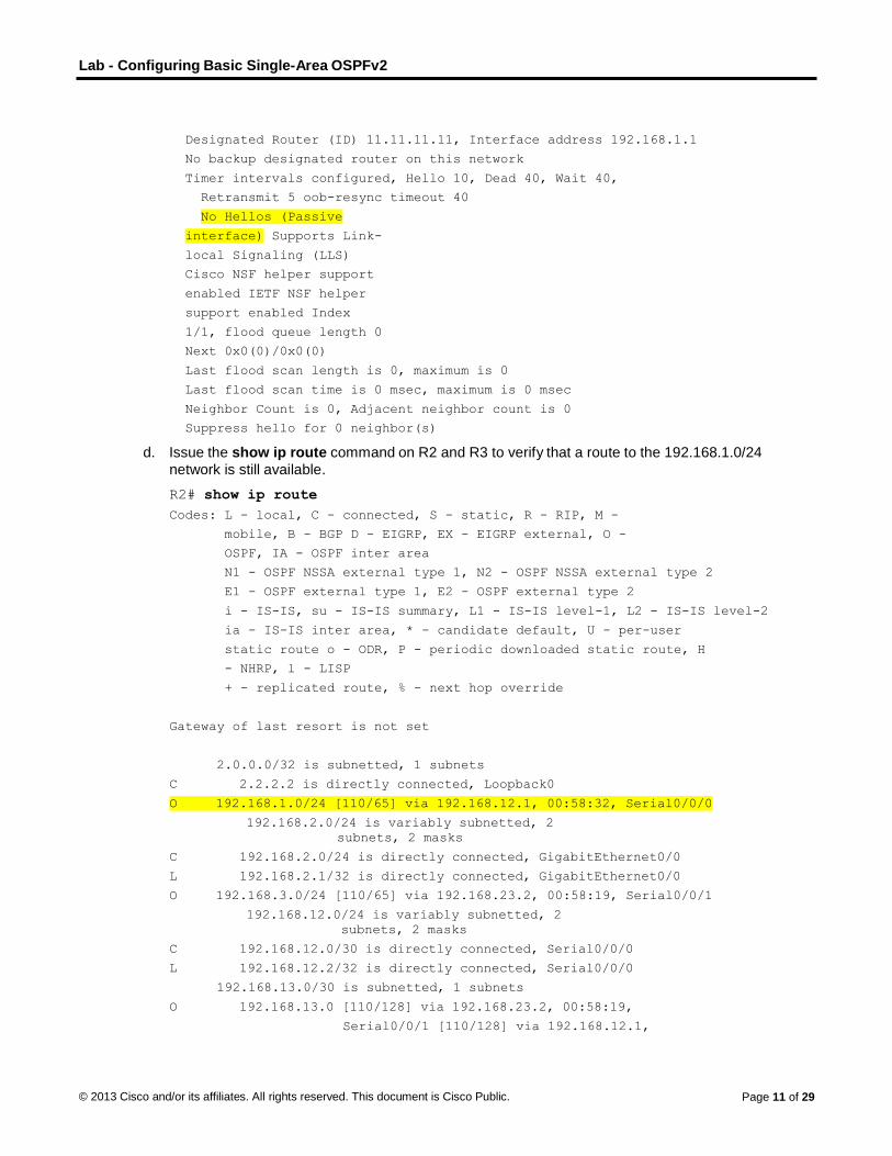
Designated Router (ID) 11.11.11.11, Interface address 192.168.1.1
No backup designated router on this network
Timer intervals configured, Hello 10, Dead 40, Wait 40,
Retransmit 5 oob-resync timeout 40
No Hellos (Passive
interface) Supports Link-
local Signaling (LLS)
Cisco NSF helper support
enabled IETF NSF helper
support enabled Index
1/1, flood queue length 0
Next 0x0(0)/0x0(0)
Last flood scan length is 0, maximum is 0
Last flood scan time is 0 msec, maximum is 0 msec
Neighbor Count is 0, Adjacent neighbor count is 0
Suppress hello for 0 neighbor(s)
d. Issue the show ip route command on R2 and R3 to verify that a route to the 192.168.1.0/24
network is still available.
R2# show ip route
Codes: L - local, C - connected, S - static, R - RIP, M -
mobile, B - BGP D - EIGRP, EX - EIGRP external, O -
OSPF, IA - OSPF inter area
N1 - OSPF NSSA external type 1, N2 - OSPF NSSA external type 2
E1 - OSPF external type 1, E2 - OSPF external type 2
i - IS-IS, su - IS-IS summary, L1 - IS-IS level-1, L2 - IS-IS level-2
ia - IS-IS inter area, * - candidate default, U - per-user
static route o - ODR, P - periodic downloaded static route, H
- NHRP, l - LISP
+ - replicated route, % - next hop override
Gateway of last resort is not set
2.0.0.0/32 is subnetted, 1 subnets
C 2.2.2.2 is directly connected, Loopback0
O 192.168.1.0/24 [110/65] via 192.168.12.1, 00:58:32, Serial0/0/0
192.168.2.0/24 is variably subnetted, 2
subnets, 2 masks
C 192.168.2.0/24 is directly connected, GigabitEthernet0/0
L 192.168.2.1/32 is directly connected, GigabitEthernet0/0
O 192.168.3.0/24 [110/65] via 192.168.23.2, 00:58:19, Serial0/0/1
192.168.12.0/24 is variably subnetted, 2
subnets, 2 masks
C 192.168.12.0/30 is directly connected, Serial0/0/0
L 192.168.12.2/32 is directly connected, Serial0/0/0
192.168.13.0/30 is subnetted, 1 subnets
O 192.168.13.0 [110/128] via 192.168.23.2, 00:58:19,
Serial0/0/1 [110/128] via 192.168.12.1,

© 2013 Cisco and/or its affiliates. All rights reserved. This document is Cisco Public. Page 12 of 29
Lab - Configuring Basic Single-Area OSPFv2
00:58:32, Serial0/0/0
192.168.23.0/24 is variably subnetted, 2
subnets, 2 masks
C 192.168.23.0/30 is directly connected, Serial0/0/1
L 192.168.23.1/32 is directly connected, Serial0/0/1