Embed Size (px)
DESCRIPTION
hhh
Citation preview
CEVB 211
SURVEYING PRACTICAL TRAINING
LABORATORY EXPERIMENT NO 6
TACHYMETRY
SECTION : 03
NAME : Zulaika Binti Mohd Fauzi : CE087587
GROUP NUMBER : 03
GROUP MEMBERS
1. Norshamirra Binti Mohd. Hijazzi CE087565
2. Antar Ali CE087529
3. Mohammed Noaman CE088674
4. Mohammad Ali Moayed CE088416
5. Haithm Awadh CE087546
6. Raziq Ahmad CE087570
7. Khaled Omar CE087550
DATE OF LABORATORY SESSION : 27.12.2012
DATE OF REPORT SUBMISSION : 26.12.201 2
LAB INSTRUCTOR : SIVADASS A/L THIRUCHELVAM
CriteriaScalePoor Acceptable Excellent
A. Appearance, formatting and grammar/ spelling.
1 2 3 4 5
B. Introduction, objective & theory 1 2 3 4 5C. List of apparatus & procedure 1 2 3 4 5D. Results: data, figures, graphs, tables, etc. 1 2 3 4 5E. Discussion 1 2 3 4 5
F. Conclusions 1 2 3 4 5
1

Table of Contents
Title Page
Abstract 3
Objective 3
Instrument 3
Procedure 3
Data Collected and Results 4-5
Calculations 6-7
Discussion / Analysis 8 -9
Conclusion 9
Appendix 9 -10
Reference 10
2

Abstract
Tachymetry is a geodetic method enabling to measure angles and distances. The aim of this
practical training is to obtain the distance indirectly by using Tachymetry (stadia method). Our
lab instructor was told us to do this tachymetry at the same location as before when we are doing
theodolite surveying which is at BJ building. All measurement from one station to another
station had been measured before. Tachymetry was performed by the means of polar method in
local coordinate system with relative heights. The advantage of this method is its good regional
availability even at places far from the workplaces.
Objective
The objective of this practical training is to obtain the distance indirectly by using Tachymetry
(stadia method). This method is derived from optic principal.
Instrument
1) Digital theodolite (1 unit).
2) Tripod (3 units).
3) Target (2 units).
4) Staff (2 units).
5) Measurement tape (1 unit).
6) Hammer/nail/spray.
Procedure
1) Racky the area and the suitable location of the stations are determined.
2) The digital theodolite is set up on station 1 and the bearing is set from station 1-2. This
will be the datum for beginning the work.
3) The observation data is recorded i.e bearing, vertical angle and the staff readings (upper,
middle and lower stadia). The codes for each surveyed features is noted.
4) Once complete, the digital theodolite is shifted to the next station and the back bearing is
set (bearing 1-2). Step 3 is repeated.
3

Data collected and result
Tachymetry Booking Form
Inst
.
Stn.
And
Ht.
of
inst.
Axis
Staf
f
stn.
Horizontal
angle
Vertical
angle, θ
Uppe
r
Stadi
a (m)
Middl
e
Stadia
(m)
Lower
Stadia
(5.297m
)
Horizontal
distance
H=100 scos2θ
(m)
Vertical distance
V=12
. 100 s sin 2θ
(m)
±V −Mid .
Reading
(m)
Ht.
of
inst
.
R.L. at
staff
(m)
Remark
s
A1 25º56’45” 1.484 1.461 1.438 4.600 0.046 -1.415 100.000
A2 87º32’14” 1.470 1.449 1.425 4.500 0.045 -1.404 100.011
1 A3 108º43’11” 00º34’04”
1.342 1.320 1.297 4.500 0.045 -1.275 1.52 100.140
A4139º35’06” 1.600 1.575 1.550 5.000 0.050 -1.525 99.900
A5 169º51’56” 1.544 1.515 1.485 5.899 0.058 -1.457 99.968
4

B1 28º12’44” 1.330 1.315 1.300 2.999 0.063 -1.252 99.895
B2 49º44’50” 1.120 1.100 1.080 3.998 0.084 -1.016 100.131
2B3
80º31’87” 01º11’57”
1.266 1.247 1.229 3.698 0.077 -1.170 1.45 99.977
B4 119º09’50” 1.292 1.277 1.260 3.199 0.067 -1.210 99.957
B5145º02’36” 1.379 1.362 1.343 3.598 0.075 -1.287 99.880
C123º07’20” 1.230 1.225 1.210 1.999 0.047 -1.178 99.697
3C2
55º55’43” 1.088 1.069 1.050 3.798 0.090 -0.979 99.896
C375º17’38” 01º21’24
”0.930 0.910 0.889 4.098 0.097 -0.813 1.34 100.06
2
C485°34′48″ 0.942 0.921 0.889 5.299 0.125 -0.796 100.07
9
C5112°00’37
”0.869 0.841 0.816 5.297 0.125 -0.716 100.15
9
5

D119º26’47” 0.702 0.679 0.657 4.407 0.651 -0.028 99.535
D254º14’01” 0.502 0.478 0.449 5.190 0.766 0.288 99.851
4D3
70º08’11” 08º17’13”
0.484 0.461 0.433 4.994 0.737 0.276 1.39 99.839
D4101°35′55″ 0.878 0.862 0.849 2.840 0.419 -0.443 99.120
D5132°47′19″ 0.871 0.858 0.844 2.644 0.390 -0.468 99.095
6

Sample calculation
The horizontal and vertical angles as well the upper, middle and lower stadia readings are
determined directly from the theodolite during the survey process.
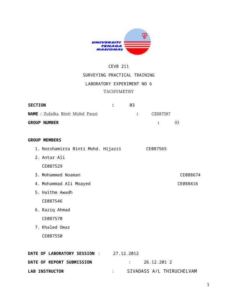
Hence, obtained for staff station A1:
Horizontal angle, = 87º32’14” Upper stadia = 1.470m
Vertical angle, = 00º34’04” Middle stadia = 1.449m
Lower stadia = 1.425m
Horizontal distance , H = 100s cos2
where s = upper stadia – lower stadia, = vertical angle ; 00º34’04”
Hence, horizontal distance for A1 = 100x (1.470-1.425) cos2 (00º34’04” )
= 4.500m
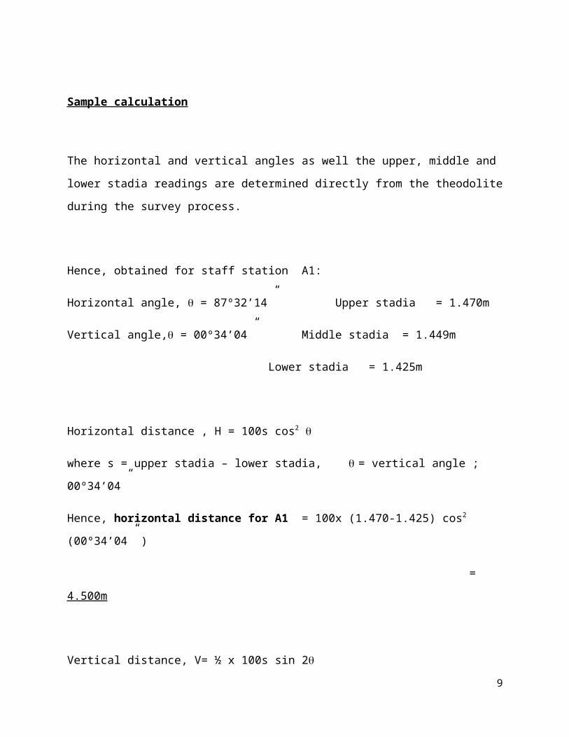
Vertical distance, V= ½ x 100s sin 2
where s = upper stadia – lower stadia, = vertical angle ; 00º34’04”
Hence, vertical distance for A1 = ½ x 100 (1.470-1.425) sin 2(00º34’04”
= 0.045m
7

±V −Mid .reading = Vertical distance – middle stadia reading
Hence, V-midreading for 1 = 0.045 -1.449
= -1.404 m
Reduced Level (RL) of staff = Known RL1 + height of instrument ± (V-mid.reading)
Here the known RL at point 1 given is 100.000m and the height of instrument measured at point
2 is 1.52m.
First, we have to find the RL of station 2 based on RL on station 1:
RL at station 2 = RL at point 1 + m ±V - HI
= 100 +1.415-1.52
= 99.895 m
Therefore RL at station 3 = RL at point 2 + HI + V – m
= 99.895 + 1.252 -1.45
= 99.697 m
8
Discussion
Generally, horizontal distances are measured by direct methods, for an example laying of chains
or tapes on ground. These methods are not always convenient if the ground is undulating, rough,
difficult and inaccessible. Under these circumstances, indirect methods are used to obtain
distances. One such method is Tacheometry. Using tacheometric methods, elevations can also be
determined. It is in fact a branch of angular surveying in which both the horizontal and vertical
positions of points are determined from the instrumental observations, the chain surveys being
entirely eliminated.
The horizontal distance that we obtained indirectly which means from the calculation are 4.600,
4.500, 4.500, 5.000 and 5.899 m at the staff station of A1, A2, A3, A4, A5 respectively. Then,
the horizontal distance at the staff station of B1, B2, B3, B4, B5 are 2.999, 3.998, 3.698, 3.199,
and 3.589 m respectively. Same goes to staff station C1, C2,C3, C4, C5 the horizontal distance
are 1.999, 3.798, 4.098, 5.299, and 5.297 m. last but not least at the staff station D1,
D2,D3,D4,D5 the horizontal distance are 4.407, 5.190, 4.994,2.840, and 2.644 m respectively.
Meanwhile, the vertical distance at the staff station A1, A2, A3, A4, A5 are 0.046, 0.045, 0.045,
0.050, and 0.058 m respectively. For the staff station at B1, B2, B3, B4, B5 the vertical distance
are 0.063, 0.084, 0.077, 0.067, 0.075 m. Then for the staff station at C1, C2,C3, C4, C5 the
vertical distance are 0.047, 0.090, 0.097, 0.125, and 0.125 m respectively. Last but not least, at
the staff station D1, D2,D3,D4,D5 the vertical distance are 0.651, 0.766, 0.737, 0.419, and 0.390
respectively.
There are a lots of difficulties faced and errors that might occurred when the experiment is
conducted means that, all distance, angle and measurements taken have errors. The problems we
have faced in this practical training like the location we have choose got many obstacle that
block our vision besides the climate was not good when we are doing this tachymetry because its
raining. Apart from that, the instrument also may not correctly leveled, means the bubble most
likely is not be in the center, then it will affect the telescope to not correctly focused. This may
9
come out with the presence of parallax. Parallax results when the optics are out of adjustment.
The parallax may be determined by nodding the head up and down while looking through the
telescope. There is no movement of the image relative to the cross hairs. Movement indicates
parallax is present and adjustment is needed. The parallax may be eliminated by properly
focusing the telescope. Furthermore, the staff is incorrectly read or not held vertical. All the
above are mistakes (blunders) and cannot be corrected unless the work is repeated.
Conclusion
In conclusion, the objective of this experiment has been satisfied. By doing this practical training
we are able to explain the principle of tachymetry, as well as we have already the stadia
principles. Overall, the results obtained from this experiment are satisfactory considering that it
meets its main objectives.
Appendices
10

Reference
1) www.tachymeter_online_tachymetry_unskilled_191773.html2) http://www.safetylit.org/citations/index.php?fuseaction=citation3) Notes given by Dr. Birima4) http://vedyadhara.ignou.ac.in/wiki/images/e/e0/UNIT_2(CRC).pdf
11


![The Green Lab - [06-A] Experiment preparation](https://img.pdfslide.us/doc/110x75/58828f3a1a28abca6d8b6289/the-green-lab-06-a-experiment-preparation.jpg)

![[HCI Lab] Week 06 Prototyping](https://img.pdfslide.us/doc/110x75/55a6227d1a28abf0278b4654/hci-lab-week-06-prototyping.jpg)