Embed Size (px)
Citation preview
INDUSTRIAL ELECTRONICS LAB REPORT
M.ZAHID TUFAIL 10-EL-60
LAB ASSIGNMENT No. 1 Characteristics of IC Temperature Sensor (LM 335)
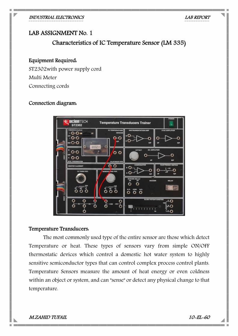
Equipment Required: ST2302with power supply cord Multi Meter Connecting cords Connection diagram:
Temperature Transducers: The most commonly used type of the entire sensor are those which detect
Temperature or heat. These types of sensors vary from simple ON/OFF thermostatic devices which control a domestic hot water system to highly sensitive semiconductor types that can control complex process control plants. Temperature Sensors measure the amount of heat energy or even coldness within an object or system, and can "sense" or detect any physical change to that temperature.
INDUSTRIAL ELECTRONICS LAB REPORT
M.ZAHID TUFAIL 10-EL-60
There are many different types of Temperature Sensors available and all have different characteristics depending upon their actual application. Temperature sensors consist of two basic physical types: Contact Types:
These types of temperature sensors are required to be in physical contact with the object being sensed and uses conduction to monitor changes in temperature. They can be used to detect solids, liquids or gases over a wide range of temperatures. Non-contact Types:
These types of temperature sensors detect the Radiant Energy being transmitted from the object in the form of Infra-red radiation. They can be used with any solid or liquid that emits radiant energy. The two basic types of contact or even non-contact temperature sensors can also be sub-divided into the following three groups of sensors, Electro-mechanical, Resistive and Electronic. LM 335:
The transducers RTD, thermistor and thermocouples have some significant limitations, e.g. thermocouples have a low output signal which varies none linearly with temperature. Also, they need some form of reference compensation. RTD's are more linear than thermocouple but the change in their resistance is very small even for large change in input temperatures i.e. they have low sensitivity. Thermistor has high sensitivity but they exhibit highly non-linear resistance temperature characteristics. For each of these transducers, electronic compensation circuits have to be used in order to overcome their shortcomings.
Also additional circuitry may be needed to increase their voltage or current output. Usually this additional electronics circuitry takes the form of monolithic integrated circuits. Thus it requires combining temperature sensing element with signal conditioning electronics to produce single monolithic IC package. The one used in ST2302 is LM 335.
INDUSTRIAL ELECTRONICS LAB REPORT
M.ZAHID TUFAIL 10-EL-60
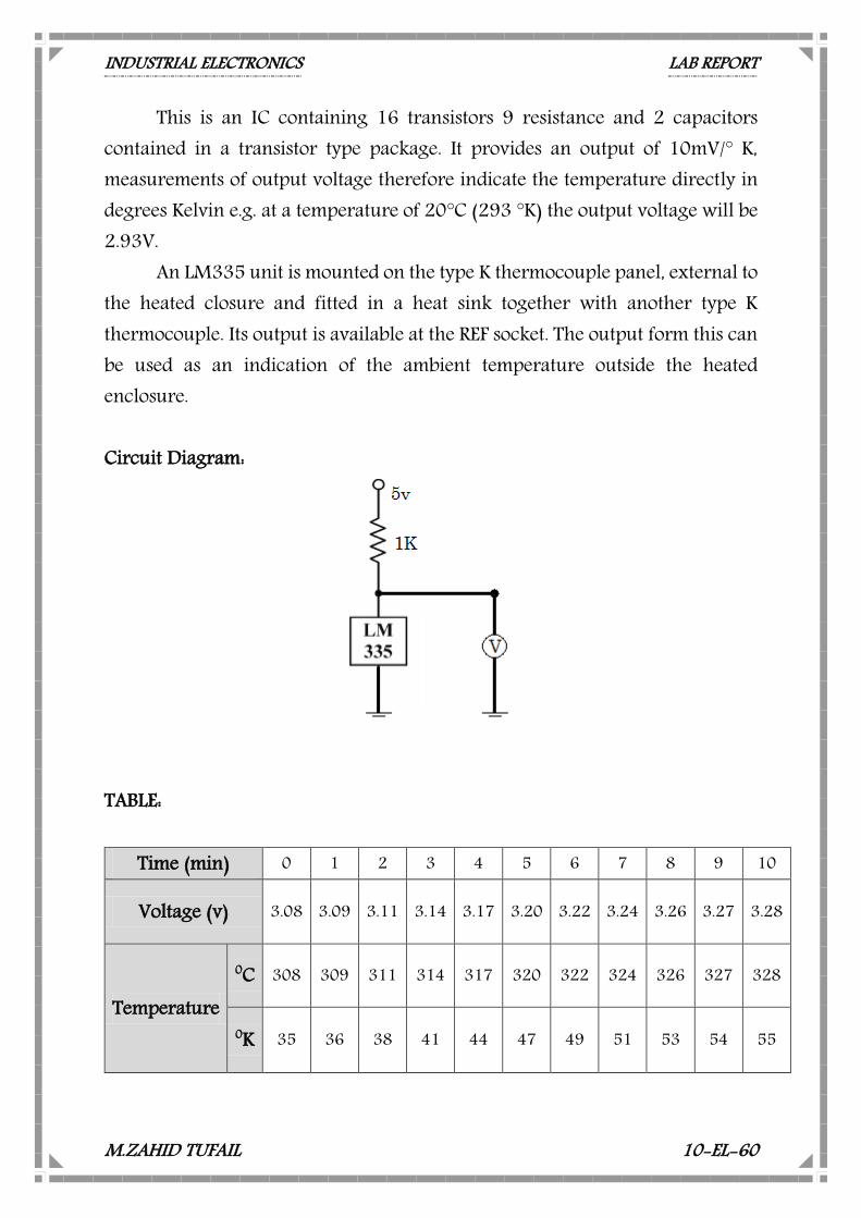
This is an IC containing 16 transistors 9 resistance and 2 capacitors contained in a transistor type package. It provides an output of 10mV/° K, measurements of output voltage therefore indicate the temperature directly in degrees Kelvin e.g. at a temperature of 20°C (293 °K) the output voltage will be 2.93V.
An LM335 unit is mounted on the type K thermocouple panel, external to the heated closure and fitted in a heat sink together with another type K thermocouple. Its output is available at the REF socket. The output form this can be used as an indication of the ambient temperature outside the heated enclosure. Circuit Diagram:
TABLE:
Time (min) 0 1 2 3 4 5 6 7 8 9 10
Voltage (v) 3.08 3.09 3.11 3.14 3.17 3.20 3.22 3.24 3.26 3.27 3.28
Temperature
0C 308 309 311 314 317 320 322 324 326 327 328
0K 35 36 38 41 44 47 49 51 53 54 55
INDUSTRIAL ELECTRONICS LAB REPORT
M.ZAHID TUFAIL 10-EL-60
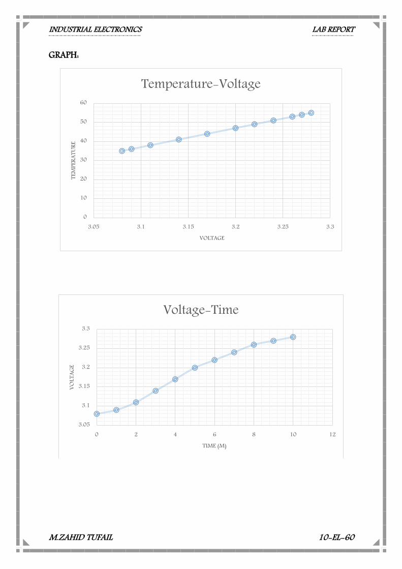
GRAPH:
3.05
3.1
3.15
3.2
3.25
3.3
0 2 4 6 8 10 12
VOLT
AGE
TIME (M)
Voltage-Time
0
10
20
30
40
50
60
3.05 3.1 3.15 3.2 3.25 3.3
TEM
PERA
TURE
VOLTAGE
Temperature-Voltage
INDUSTRIAL ELECTRONICS LAB REPORT
M.ZAHID TUFAIL 10-EL-60
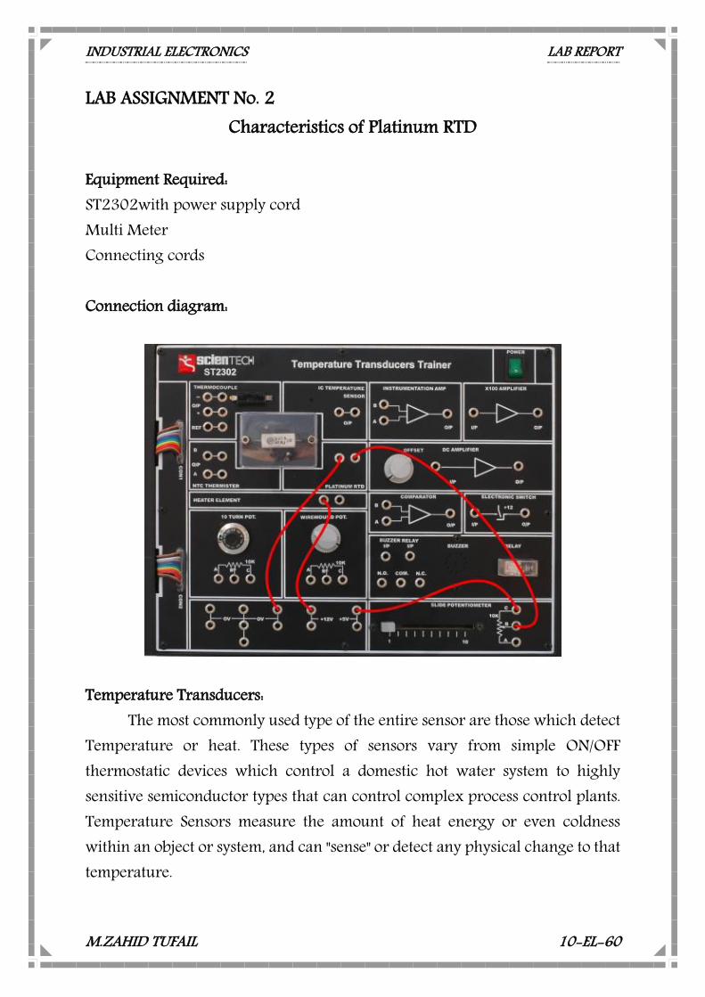
LAB ASSIGNMENT No. 2 Characteristics of Platinum RTD
Equipment Required: ST2302with power supply cord Multi Meter Connecting cords Connection diagram:
Temperature Transducers:
The most commonly used type of the entire sensor are those which detect Temperature or heat. These types of sensors vary from simple ON/OFF thermostatic devices which control a domestic hot water system to highly sensitive semiconductor types that can control complex process control plants. Temperature Sensors measure the amount of heat energy or even coldness within an object or system, and can "sense" or detect any physical change to that temperature.
INDUSTRIAL ELECTRONICS LAB REPORT
M.ZAHID TUFAIL 10-EL-60
There are many different types of Temperature Sensors available and all have different characteristics depending upon their actual application. Temperature sensors consist of two basic physical types: Contact Types:
These types of temperature sensors are required to be in physical contact with the object being sensed and uses conduction to monitor changes in temperature. They can be used to detect solids, liquids or gases over a wide range of temperatures. Non-contact Types:
These types of temperature sensors detect the Radiant Energy being transmitted from the object in the form of Infra-red radiation. They can be used with any solid or liquid that emits radiant energy. The two basic types of contact or even non-contact temperature sensors can also be sub-divided into the following three groups of sensors, Electro-mechanical, Resistive and Electronic. RTD:
The variation in resistance of a metal with variation in temperature is the basis of temperature measurement in a Platinum RTD. The metal generally used is platinum or tungsten. Platinum is especially suited for this purpose, as it can shows limited susceptibility to contamination. All metals produce a positive change in resistance with temperature. This of course is the main function of an RTD. This implies a metal with high value of resistance should be used for RTD’s.
The requirements of a conductor material to be used in RTD’s are:
The change in resistance of material per unit change in temperature should be as large as possible. The material should have high value of resistance so that minimum volume of material is used for the construction of RTD. The resistance of material should have continuous and stable relationship with temperature.
INDUSTRIAL ELECTRONICS LAB REPORT
M.ZAHID TUFAIL 10-EL-60
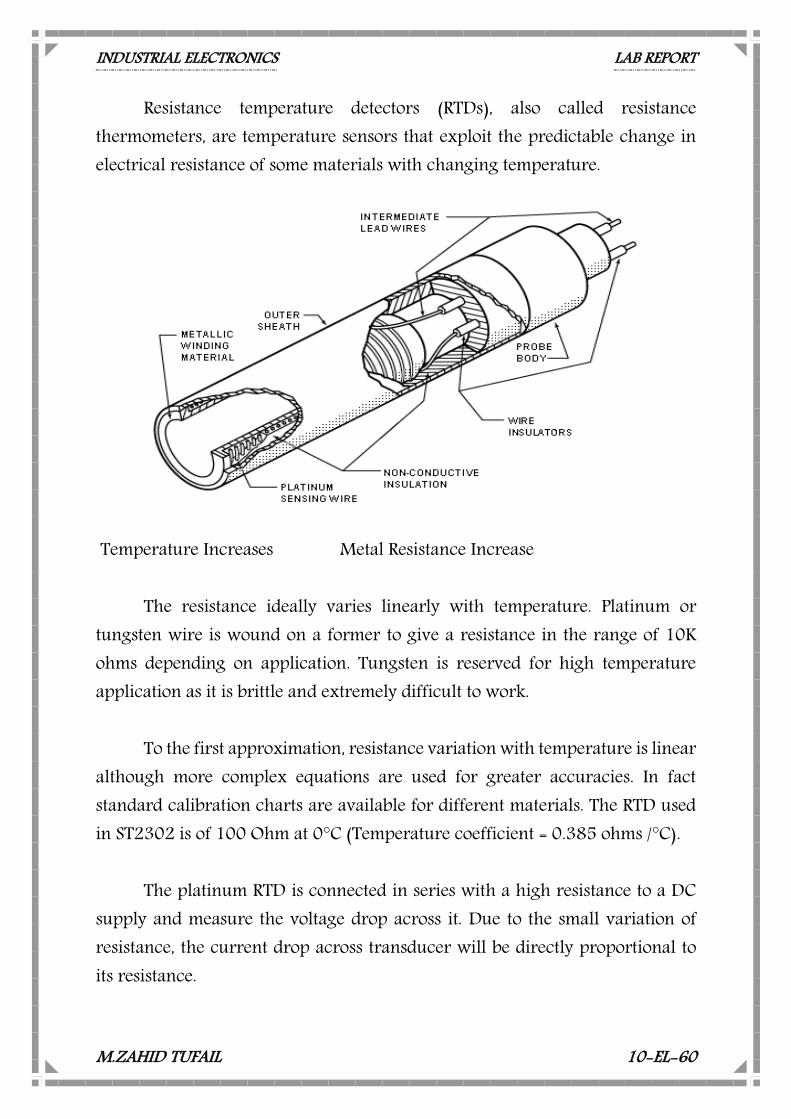
Resistance temperature detectors (RTDs), also called resistance thermometers, are temperature sensors that exploit the predictable change in electrical resistance of some materials with changing temperature.
Temperature Increases Metal Resistance Increase
The resistance ideally varies linearly with temperature. Platinum or tungsten wire is wound on a former to give a resistance in the range of 10K ohms depending on application. Tungsten is reserved for high temperature application as it is brittle and extremely difficult to work.
To the first approximation, resistance variation with temperature is linear
although more complex equations are used for greater accuracies. In fact standard calibration charts are available for different materials. The RTD used in ST2302 is of 100 Ohm at 0°C (Temperature coefficient = 0.385 ohms /°C).
The platinum RTD is connected in series with a high resistance to a DC
supply and measure the voltage drop across it. Due to the small variation of resistance, the current drop across transducer will be directly proportional to its resistance.
INDUSTRIAL ELECTRONICS LAB REPORT
M.ZAHID TUFAIL 10-EL-60
The RTD consists of a thin film of platinum deposited on a ceramic substrate with gold contact-plates on each end. The platinum resistance temperature detector is a highly stable and accurate sensor. The resistance increases linearly at 0.385 Ohm/°C. To develop a voltage a suitable resistance should be connected between output and +5V and the wire-wound potentiometer is recommended. The RTD is located in the transparent plastic heating compartment. RTD – sensitivity: • Sensitivity is shown by the value αo
Platinum – 0.004/ °C Nickel – 0.005/ °C
• Thus, for a 100Ω platinum RTD, a change of only 0.4 Ω would be expected if the temperature is changed by 1°C RTD – response time
• Generally 0.5 to 5 seconds or more •The slowness of response is due principally to the slowness of thermal conductivity in bringing the device into thermal equilibrium with its environment.
INDUSTRIAL ELECTRONICS LAB REPORT
M.ZAHID TUFAIL 10-EL-60
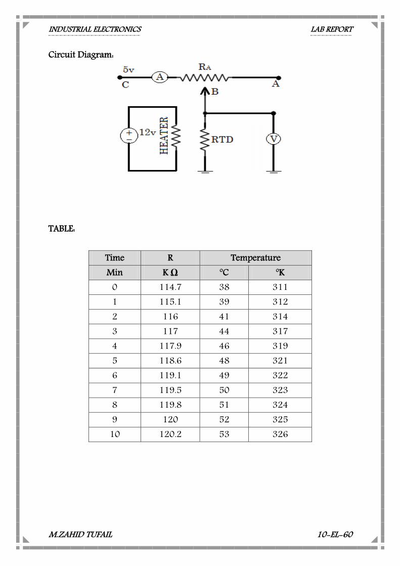
Circuit Diagram:
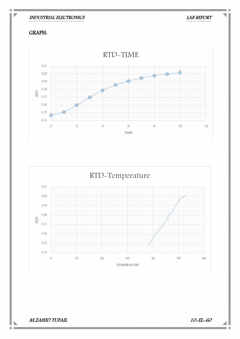
TABLE:
Time R Temperature Min K Ω oC oK
0 114.7 38 311 1 115.1 39 312 2 116 41 314 3 117 44 317 4 117.9 46 319 5 118.6 48 321 6 119.1 49 322 7 119.5 50 323 8 119.8 51 324 9 120 52 325
10 120.2 53 326
INDUSTRIAL ELECTRONICS LAB REPORT
M.ZAHID TUFAIL 10-EL-60
GRAPH:
114
115
116
117
118
119
120
121
0 2 4 6 8 10 12
RTD
TIME
RTD-TIME
114
115
116
117
118
119
120
121
0 10 20 30 40 50 60
RTD
TEMPERATURE
RTD-Temperature
INDUSTRIAL ELECTRONICS LAB REPORT
M.ZAHID TUFAIL 10-EL-60
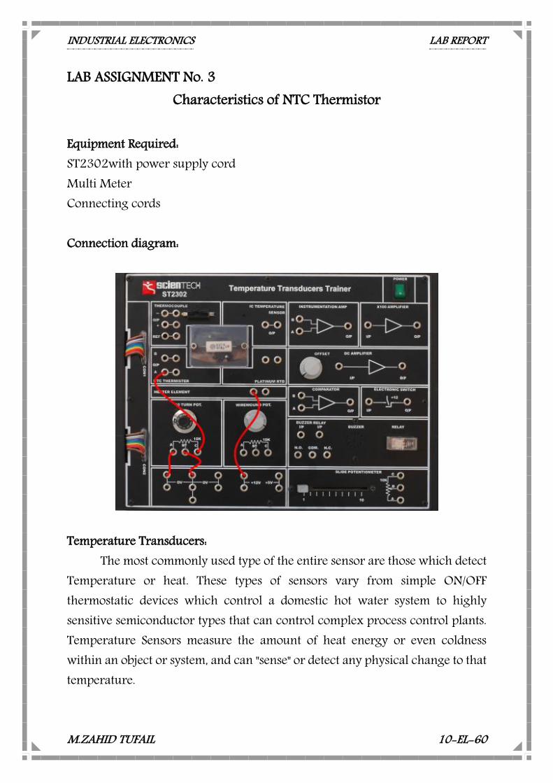
LAB ASSIGNMENT No. 3 Characteristics of NTC Thermistor
Equipment Required: ST2302with power supply cord Multi Meter Connecting cords Connection diagram:
Temperature Transducers:
The most commonly used type of the entire sensor are those which detect Temperature or heat. These types of sensors vary from simple ON/OFF thermostatic devices which control a domestic hot water system to highly sensitive semiconductor types that can control complex process control plants. Temperature Sensors measure the amount of heat energy or even coldness within an object or system, and can "sense" or detect any physical change to that temperature.

INDUSTRIAL ELECTRONICS LAB REPORT
M.ZAHID TUFAIL 10-EL-60
There are many different types of Temperature Sensors available and all have different characteristics depending upon their actual application. Temperature sensors consist of two basic physical types: Contact Types:
These types of temperature sensors are required to be in physical contact with the object being sensed and uses conduction to monitor changes in temperature. They can be used to detect solids, liquids or gases over a wide range of temperatures. Non-contact Types:
These types of temperature sensors detect the Radiant Energy being transmitted from the object in the form of Infra-red radiation. They can be used with any solid or liquid that emits radiant energy. The two basic types of contact or even non-contact temperature sensors can also be sub-divided into the following three groups of sensors, Electro-mechanical, Resistive and Electronic. Thermistor:
Thermistor is a contraction of a term thermal resistor. Although positive temperature co-efficient of unit exhibit an increase in the value of resistance with increase in temperature are available, most Thermistor have a negative temperature coefficient i.e. their resistance decreases with increase in temperature. In some materials the resistance of Thermistor at room temperature may decrease as much as 6% for 1°C rise in temperature. This high sensitivity to temperature change make the Thermistor extremely well suited to precision temperature measurement, control & compensation.
Therefore, especially in lower temperatures range of -100°C to 300°C, or
to detect very small changes in temperature which cannot be observed with an RTD or a thermocouple. Thermistor is composed of a sintered mixture of metallic oxides, such as Mn, Ni, Co, Cu, Fe, & U. Their resistance range from 0.5 Ω to 75MΩ and they are available in wide variety of shapes and sizes.
INDUSTRIAL ELECTRONICS LAB REPORT
M.ZAHID TUFAIL 10-EL-60
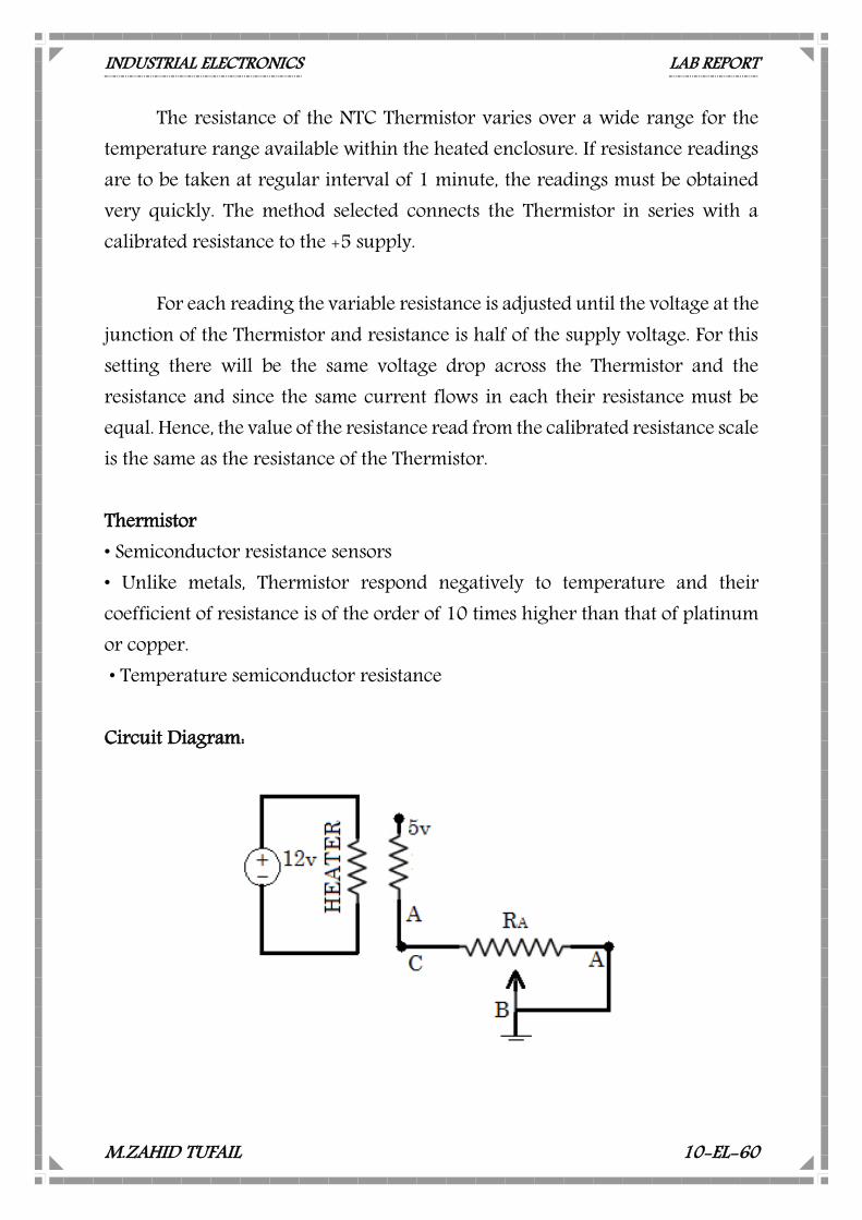
The resistance of the NTC Thermistor varies over a wide range for the temperature range available within the heated enclosure. If resistance readings are to be taken at regular interval of 1 minute, the readings must be obtained very quickly. The method selected connects the Thermistor in series with a calibrated resistance to the +5 supply.
For each reading the variable resistance is adjusted until the voltage at the junction of the Thermistor and resistance is half of the supply voltage. For this setting there will be the same voltage drop across the Thermistor and the resistance and since the same current flows in each their resistance must be equal. Hence, the value of the resistance read from the calibrated resistance scale is the same as the resistance of the Thermistor. Thermistor • Semiconductor resistance sensors • Unlike metals, Thermistor respond negatively to temperature and their coefficient of resistance is of the order of 10 times higher than that of platinum or copper. • Temperature semiconductor resistance Circuit Diagram:
INDUSTRIAL ELECTRONICS LAB REPORT
M.ZAHID TUFAIL 10-EL-60
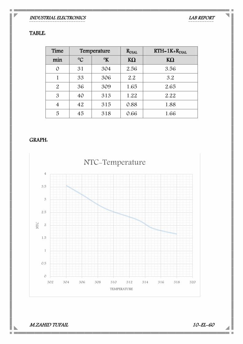
TABLE:
Time Temperature RDIAL RTH=1K+RDIAL min oC oK KΩ KΩ
0 31 304 2.56 3.56 1 33 306 2.2 3.2 2 36 309 1.65 2.65 3 40 313 1.22 2.22 4 42 315 0.88 1.88 5 45 318 0.66 1.66
GRAPH:
0
0.5
1
1.5
2
2.5
3
3.5
4
302 304 306 308 310 312 314 316 318 320
NTC
TEMPERATURE
NTC-Temperature
INDUSTRIAL ELECTRONICS LAB REPORT
M.ZAHID TUFAIL 10-EL-60
LAB ASSIGNMENT No. 4 Characteristics of NTC Bridge circuit
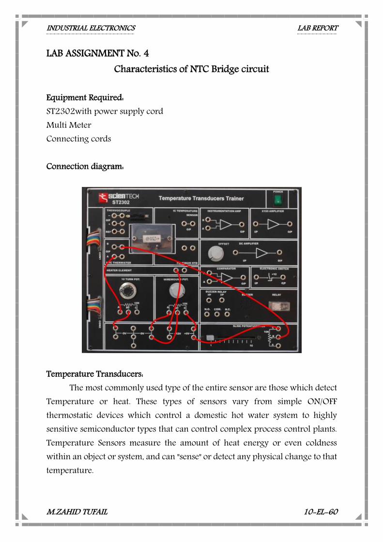
Equipment Required: ST2302with power supply cord Multi Meter Connecting cords Connection diagram:
Temperature Transducers:
The most commonly used type of the entire sensor are those which detect Temperature or heat. These types of sensors vary from simple ON/OFF thermostatic devices which control a domestic hot water system to highly sensitive semiconductor types that can control complex process control plants. Temperature Sensors measure the amount of heat energy or even coldness within an object or system, and can "sense" or detect any physical change to that temperature.
INDUSTRIAL ELECTRONICS LAB REPORT
M.ZAHID TUFAIL 10-EL-60
There are many different types of Temperature Sensors available and all have different characteristics depending upon their actual application. Temperature sensors consist of two basic physical types: Contact Types:
These types of temperature sensors are required to be in physical contact with the object being sensed and uses conduction to monitor changes in temperature. They can be used to detect solids, liquids or gases over a wide range of temperatures. Non-contact Types:
These types of temperature sensors detect the Radiant Energy being transmitted from the object in the form of Infra-red radiation. They can be used with any solid or liquid that emits radiant energy. The two basic types of contact or even non-contact temperature sensors can also be sub-divided into the following three groups of sensors, Electro-mechanical, Resistive and Electronic. Thermistor:
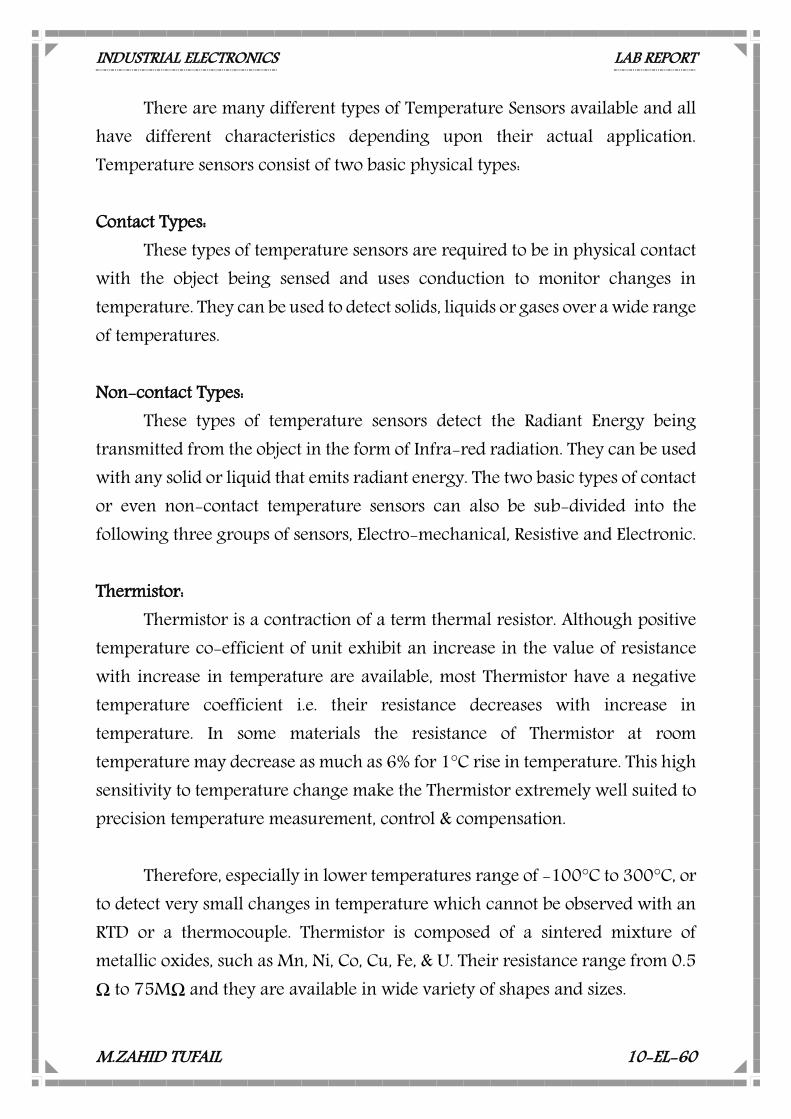
Thermistor is a contraction of a term thermal resistor. Although positive temperature co-efficient of unit exhibit an increase in the value of resistance with increase in temperature are available, most Thermistor have a negative temperature coefficient i.e. their resistance decreases with increase in temperature. In some materials the resistance of Thermistor at room temperature may decrease as much as 6% for 1°C rise in temperature. This high sensitivity to temperature change make the Thermistor extremely well suited to precision temperature measurement, control & compensation.
Therefore, especially in lower temperatures range of -100°C to 300°C, or
to detect very small changes in temperature which cannot be observed with an RTD or a thermocouple. Thermistor is composed of a sintered mixture of metallic oxides, such as Mn, Ni, Co, Cu, Fe, & U. Their resistance range from 0.5 Ω to 75MΩ and they are available in wide variety of shapes and sizes.
INDUSTRIAL ELECTRONICS LAB REPORT
M.ZAHID TUFAIL 10-EL-60
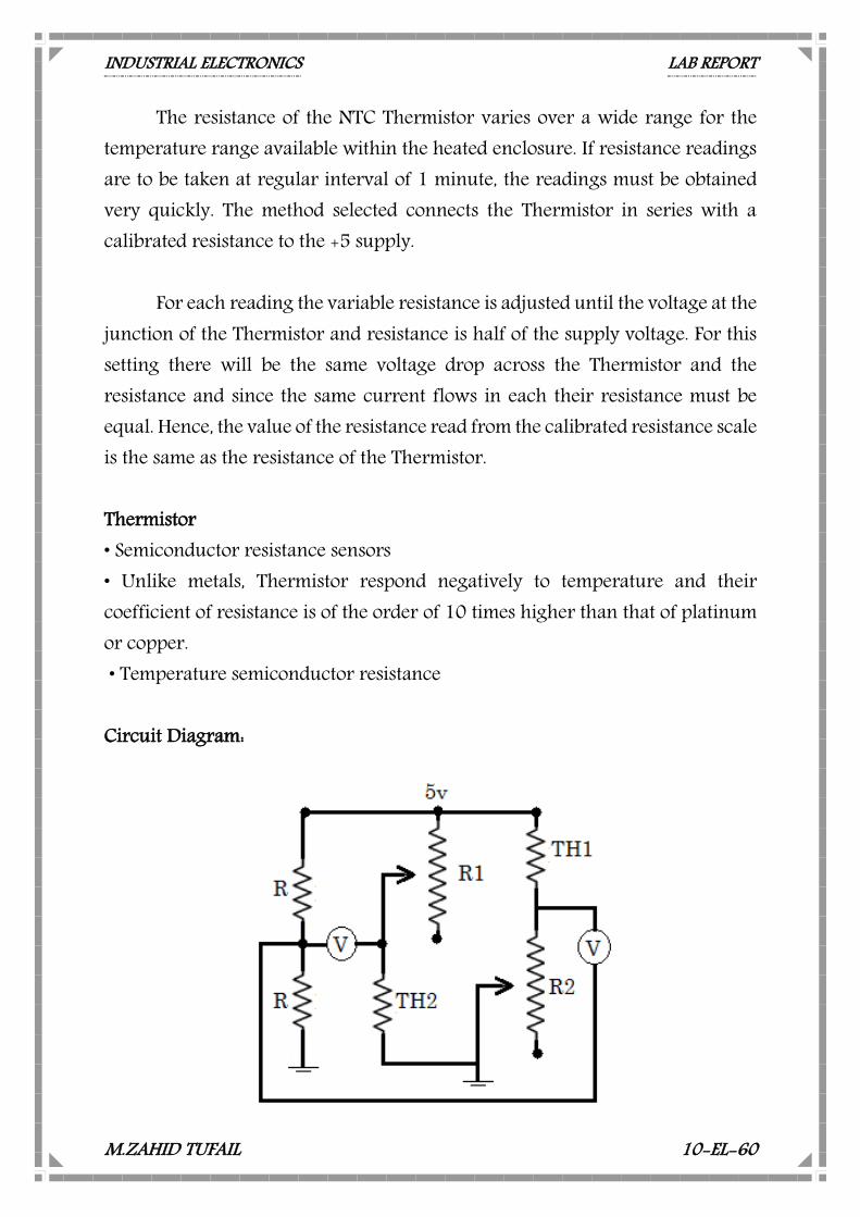
The resistance of the NTC Thermistor varies over a wide range for the temperature range available within the heated enclosure. If resistance readings are to be taken at regular interval of 1 minute, the readings must be obtained very quickly. The method selected connects the Thermistor in series with a calibrated resistance to the +5 supply.
For each reading the variable resistance is adjusted until the voltage at the junction of the Thermistor and resistance is half of the supply voltage. For this setting there will be the same voltage drop across the Thermistor and the resistance and since the same current flows in each their resistance must be equal. Hence, the value of the resistance read from the calibrated resistance scale is the same as the resistance of the Thermistor. Thermistor • Semiconductor resistance sensors • Unlike metals, Thermistor respond negatively to temperature and their coefficient of resistance is of the order of 10 times higher than that of platinum or copper. • Temperature semiconductor resistance Circuit Diagram:
INDUSTRIAL ELECTRONICS LAB REPORT
M.ZAHID TUFAIL 10-EL-60
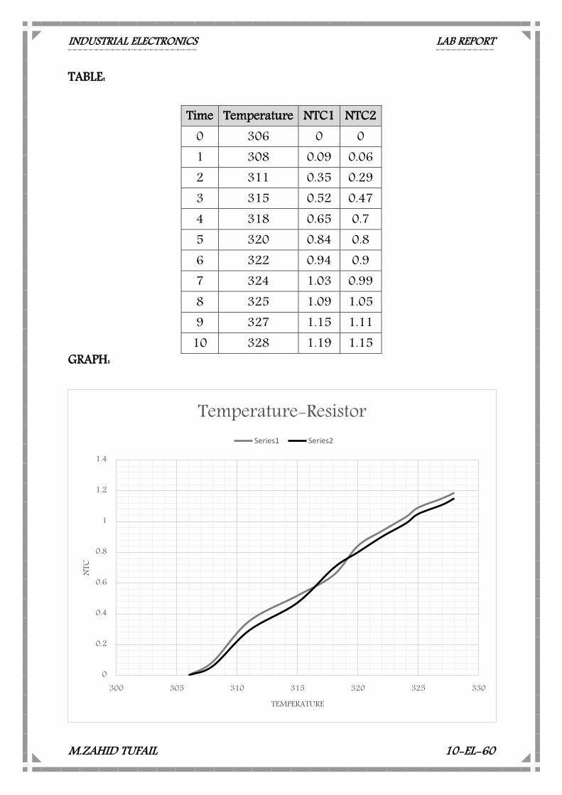
TABLE: GRAPH:
0
0.2
0.4
0.6
0.8
1
1.2
1.4
300 305 310 315 320 325 330
NTC
TEMPERATURE
Temperature-ResistorSeries1 Series2
Time Temperature NTC1 NTC2 0 306 0 0 1 308 0.09 0.06 2 311 0.35 0.29 3 315 0.52 0.47 4 318 0.65 0.7 5 320 0.84 0.8 6 322 0.94 0.9 7 324 1.03 0.99 8 325 1.09 1.05 9 327 1.15 1.11
10 328 1.19 1.15
INDUSTRIAL ELECTRONICS LAB REPORT
M.ZAHID TUFAIL 10-EL-60
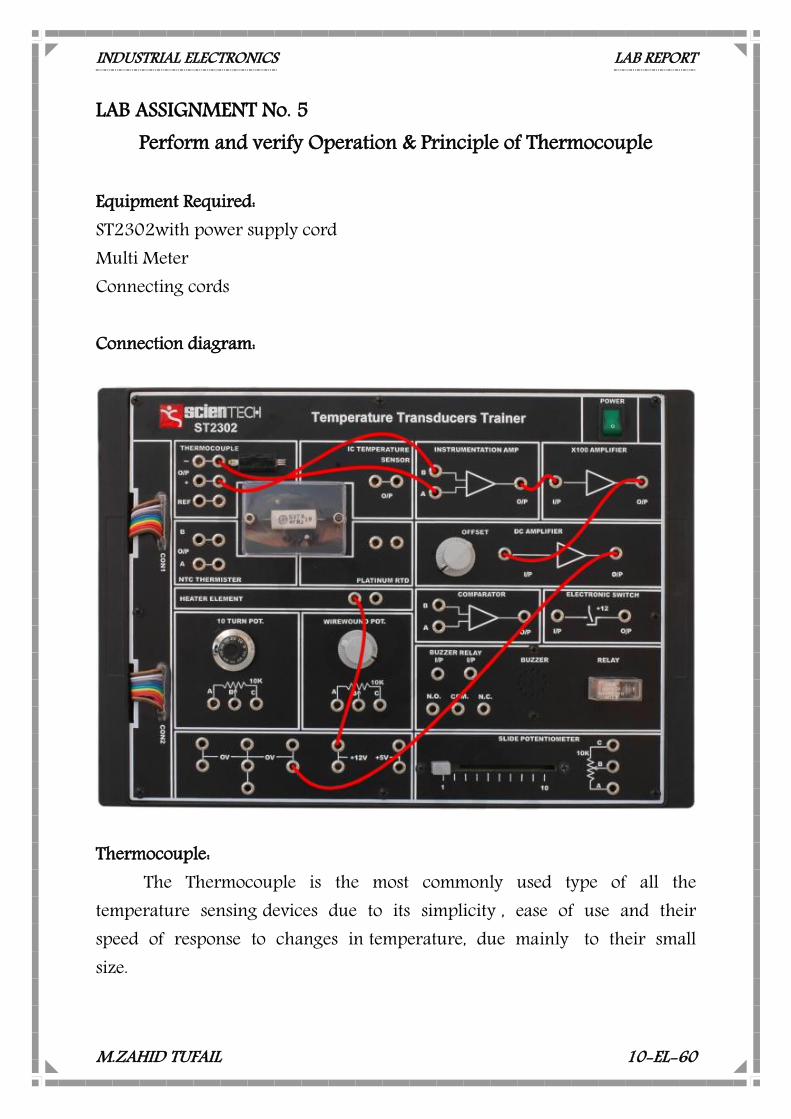
LAB ASSIGNMENT No. 5 Perform and verify Operation & Principle of Thermocouple
Equipment Required: ST2302with power supply cord Multi Meter Connecting cords Connection diagram:
Thermocouple:
The Thermocouple is the most commonly used type of all the temperature sensing devices due to its simplicity , ease of use and their speed of response to changes in temperature, due mainly to their small size.
INDUSTRIAL ELECTRONICS LAB REPORT
M.ZAHID TUFAIL 10-EL-60
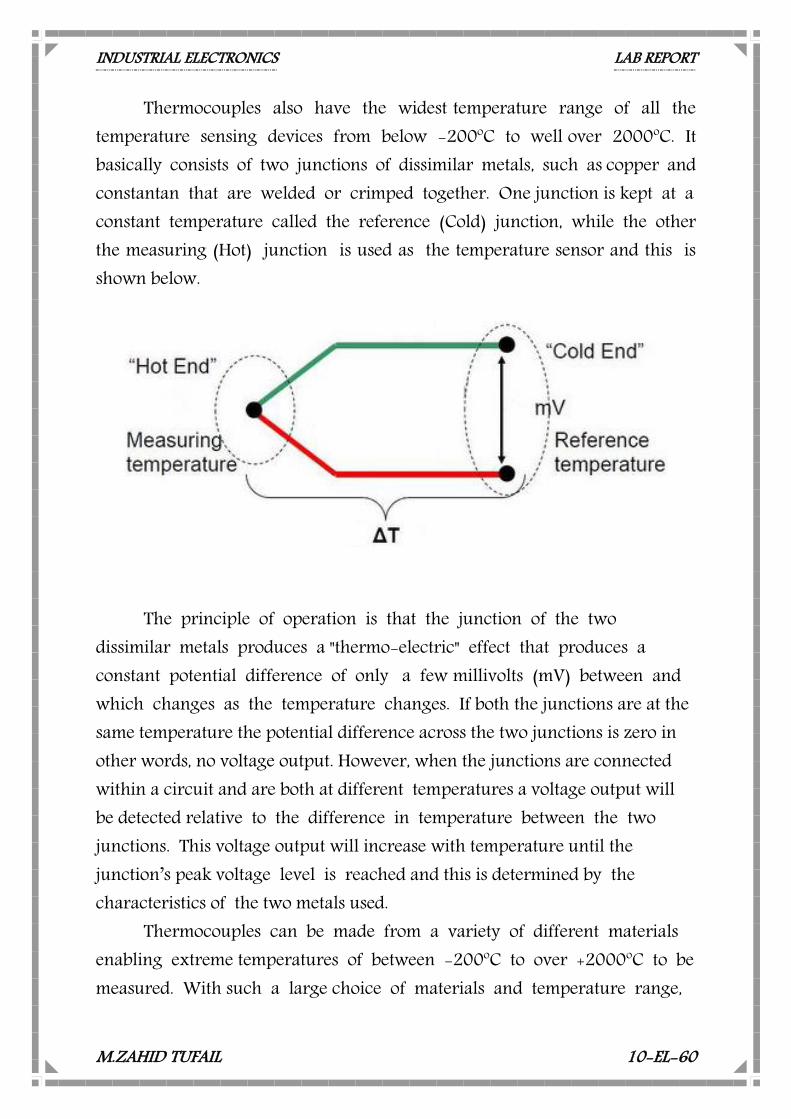
Thermocouples also have the widest temperature range of all the temperature sensing devices from below -200oC to well over 2000oC. It basically consists of two junctions of dissimilar metals, such as copper and constantan that are welded or crimped together. One junction is kept at a constant temperature called the reference (Cold) junction, while the other the measuring (Hot) junction is used as the temperature sensor and this is shown below.
The principle of operation is that the junction of the two dissimilar metals produces a "thermo-electric" effect that produces a constant potential difference of only a few millivolts (mV) between and which changes as the temperature changes. If both the junctions are at the same temperature the potential difference across the two junctions is zero in other words, no voltage output. However, when the junctions are connected within a circuit and are both at different temperatures a voltage output will be detected relative to the difference in temperature between the two junctions. This voltage output will increase with temperature until the junction’s peak voltage level is reached and this is determined by the characteristics of the two metals used.
Thermocouples can be made from a variety of different materials enabling extreme temperatures of between -200oC to over +2000oC to be measured. With such a large choice of materials and temperature range,
INDUSTRIAL ELECTRONICS LAB REPORT
M.ZAHID TUFAIL 10-EL-60
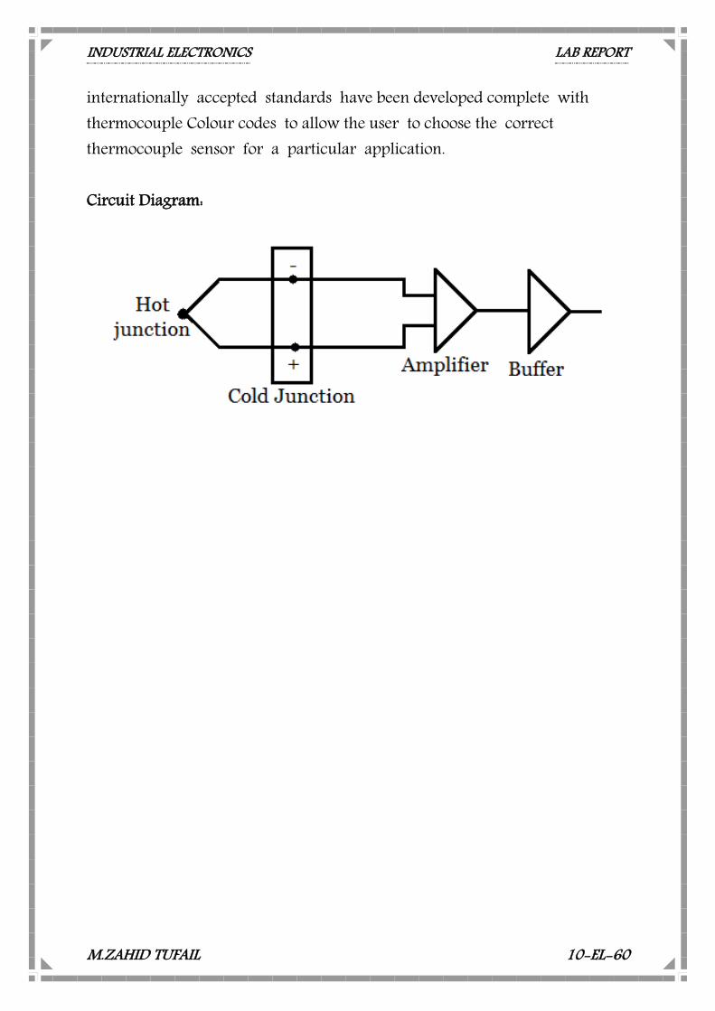
internationally accepted standards have been developed complete with thermocouple Colour codes to allow the user to choose the correct thermocouple sensor for a particular application. Circuit Diagram:
INDUSTRIAL ELECTRONICS LAB REPORT
M.ZAHID TUFAIL 10-EL-60
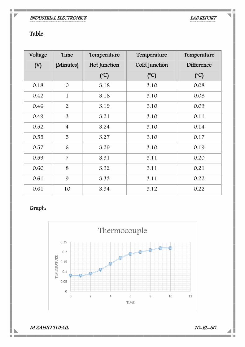
Table:
Graph:
0
0.05
0.1
0.15
0.2
0.25
0 2 4 6 8 10 12
TEM
PERA
TURE
TIME
Thermocouple
Voltage (V)
Time (Minutes)
Temperature Hot Junction
(oC)
Temperature Cold Junction
(oC)
Temperature Difference
(oC) 0.18 0 3.18 3.10 0.08 0.42 1 3.18 3.10 0.08 0.46 2 3.19 3.10 0.09 0.49 3 3.21 3.10 0.11 0.52 4 3.24 3.10 0.14 0.55 5 3.27 3.10 0.17 0.57 6 3.29 3.10 0.19 0.59 7 3.31 3.11 0.20 0.60 8 3.32 3.11 0.21 0.61 9 3.33 3.11 0.22 0.61 10 3.34 3.12 0.22
INDUSTRIAL ELECTRONICS LAB REPORT
M.ZAHID TUFAIL 10-EL-60
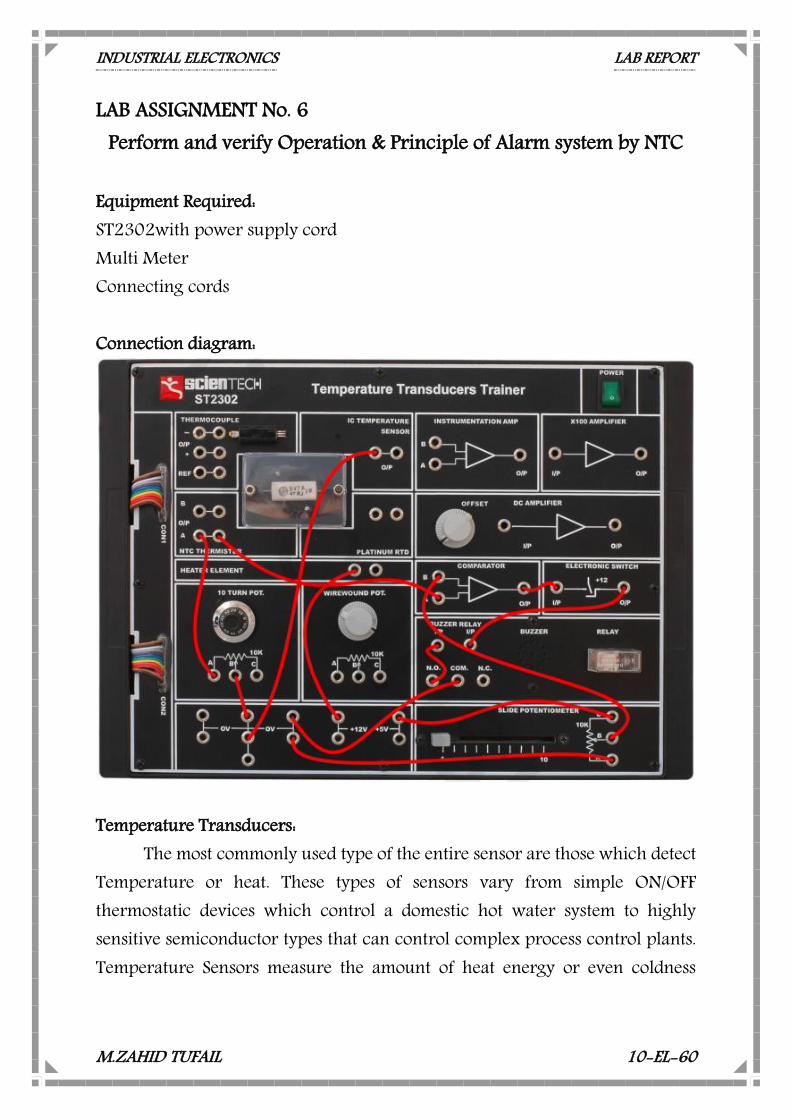
LAB ASSIGNMENT No. 6 Perform and verify Operation & Principle of Alarm system by NTC
Equipment Required: ST2302with power supply cord Multi Meter Connecting cords Connection diagram:
Temperature Transducers:
The most commonly used type of the entire sensor are those which detect Temperature or heat. These types of sensors vary from simple ON/OFF thermostatic devices which control a domestic hot water system to highly sensitive semiconductor types that can control complex process control plants. Temperature Sensors measure the amount of heat energy or even coldness

INDUSTRIAL ELECTRONICS LAB REPORT
M.ZAHID TUFAIL 10-EL-60
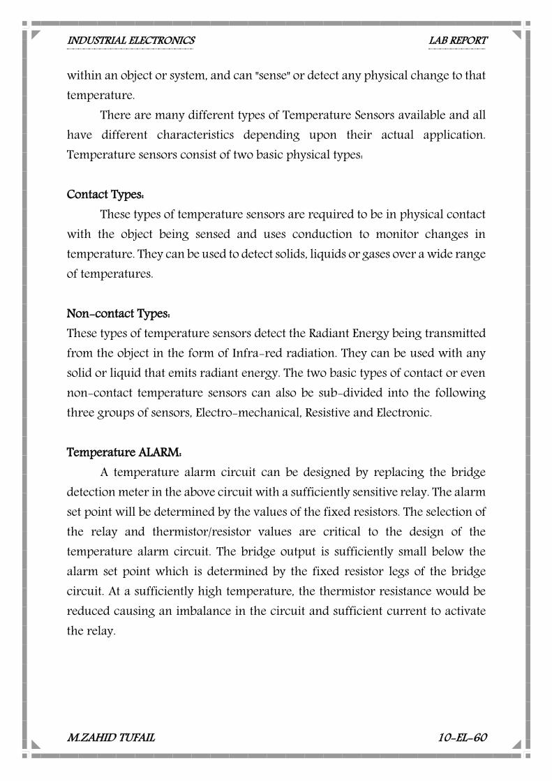
within an object or system, and can "sense" or detect any physical change to that temperature.
There are many different types of Temperature Sensors available and all have different characteristics depending upon their actual application. Temperature sensors consist of two basic physical types: Contact Types:
These types of temperature sensors are required to be in physical contact with the object being sensed and uses conduction to monitor changes in temperature. They can be used to detect solids, liquids or gases over a wide range of temperatures. Non-contact Types: These types of temperature sensors detect the Radiant Energy being transmitted from the object in the form of Infra-red radiation. They can be used with any solid or liquid that emits radiant energy. The two basic types of contact or even non-contact temperature sensors can also be sub-divided into the following three groups of sensors, Electro-mechanical, Resistive and Electronic. Temperature ALARM:
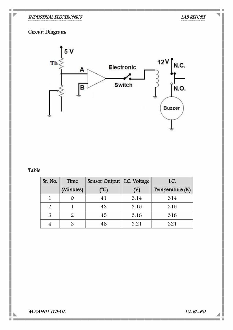
A temperature alarm circuit can be designed by replacing the bridge detection meter in the above circuit with a sufficiently sensitive relay. The alarm set point will be determined by the values of the fixed resistors. The selection of the relay and thermistor/resistor values are critical to the design of the temperature alarm circuit. The bridge output is sufficiently small below the alarm set point which is determined by the fixed resistor legs of the bridge circuit. At a sufficiently high temperature, the thermistor resistance would be reduced causing an imbalance in the circuit and sufficient current to activate the relay.

INDUSTRIAL ELECTRONICS LAB REPORT
M.ZAHID TUFAIL 10-EL-60
Temperature was one of the first physical parameters to be measured in the process field and has been sensed in just about every way imaginable over the years. At one time or another, just about every physical property that changes with respect to temperature has been used as a basis for this measurement. Over the last few years, the development of low cost, small controllers and associated electronics circuitry has allowed for the cost effective measurement and control of temperature that was not possible before. NTC thermistor elements, either alone or as part of temperature sensing assembly, are being utilized more and more where the need to sense or control temperature is needed.
NTC thermistors offer designers many advantages over other type of sensing technologies including the highest sensitivity to temperature changes, high signal to noise ratio, simple operation as well as being low cost. Formerly, the nonlinear resistance versus temperature characteristic was problematic in analog sensing circuits. Today, however, with the advent of digital electronic controls the translation is handled via equations in software or lookup tables. The reliability, performance and longevity of the NTC thermistor as well as its other inherent characteristics has made it the temperature sensing element of choice where precise measurement and control of temperature are necessary. NTC thermistor applications make use of the characteristics inherent in their composition. Applications are generally broken up into two separate categories that utilize different characteristics of the NTC thermistor.
INDUSTRIAL ELECTRONICS LAB REPORT
M.ZAHID TUFAIL 10-EL-60
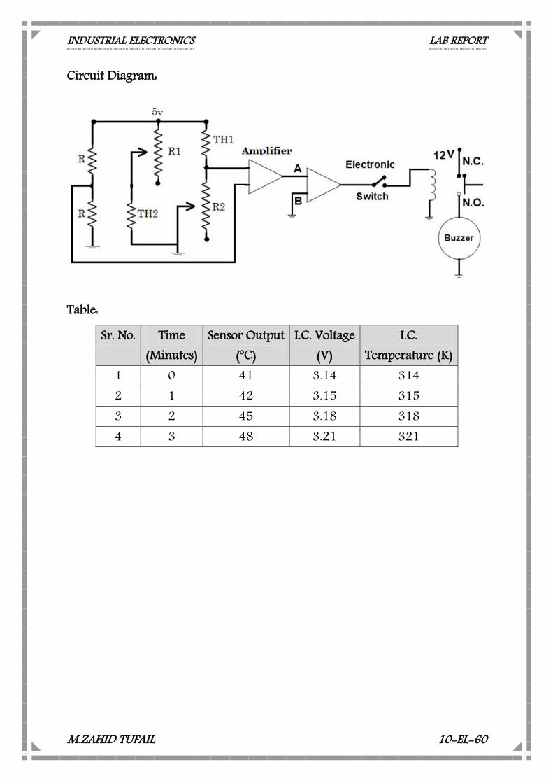
Circuit Diagram:
Table:
Sr. No. Time (Minutes)
Sensor Output (oC)
I.C. Voltage (V)
I.C. Temperature (K)
1 0 41 3.14 314 2 1 42 3.15 315 3 2 45 3.18 318 4 3 48 3.21 321
INDUSTRIAL ELECTRONICS LAB REPORT
M.ZAHID TUFAIL 10-EL-60
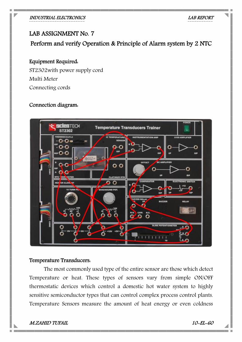
LAB ASSIGNMENT No. 7 Perform and verify Operation & Principle of Alarm system by 2 NTC Equipment Required: ST2302with power supply cord Multi Meter Connecting cords Connection diagram:
Temperature Transducers:
The most commonly used type of the entire sensor are those which detect Temperature or heat. These types of sensors vary from simple ON/OFF thermostatic devices which control a domestic hot water system to highly sensitive semiconductor types that can control complex process control plants. Temperature Sensors measure the amount of heat energy or even coldness
INDUSTRIAL ELECTRONICS LAB REPORT
M.ZAHID TUFAIL 10-EL-60
within an object or system, and can "sense" or detect any physical change to that temperature.
There are many different types of Temperature Sensors available and all have different characteristics depending upon their actual application. Temperature sensors consist of two basic physical types: Contact Types:
These types of temperature sensors are required to be in physical contact with the object being sensed and uses conduction to monitor changes in temperature. They can be used to detect solids, liquids or gases over a wide range of temperatures. Non-contact Types: These types of temperature sensors detect the Radiant Energy being transmitted from the object in the form of Infra-red radiation. They can be used with any solid or liquid that emits radiant energy. The two basic types of contact or even non-contact temperature sensors can also be sub-divided into the following three groups of sensors, Electro-mechanical, Resistive and Electronic. Temperature ALARM:
A temperature alarm circuit can be designed by replacing the bridge detection meter in the above circuit with a sufficiently sensitive relay. The alarm set point will be determined by the values of the fixed resistors. The selection of the relay and thermistor/resistor values are critical to the design of the temperature alarm circuit. The bridge output is sufficiently small below the alarm set point which is determined by the fixed resistor legs of the bridge circuit. At a sufficiently high temperature, the thermistor resistance would be reduced causing an imbalance in the circuit and sufficient current to activate the relay.
INDUSTRIAL ELECTRONICS LAB REPORT
M.ZAHID TUFAIL 10-EL-60
Temperature was one of the first physical parameters to be measured in the process field and has been sensed in just about every way imaginable over the years. At one time or another, just about every physical property that changes with respect to temperature has been used as a basis for this measurement. Over the last few years, the development of low cost, small controllers and associated electronics circuitry has allowed for the cost effective measurement and control of temperature that was not possible before. NTC thermistor elements, either alone or as part of temperature sensing assembly, are being utilized more and more where the need to sense or control temperature is needed.
NTC thermistors offer designers many advantages over other type of sensing technologies including the highest sensitivity to temperature changes, high signal to noise ratio, simple operation as well as being low cost. Formerly, the nonlinear resistance versus temperature characteristic was problematic in analog sensing circuits. Today, however, with the advent of digital electronic controls the translation is handled via equations in software or lookup tables. The reliability, performance and longevity of the NTC thermistor as well as its other inherent characteristics has made it the temperature sensing element of choice where precise measurement and control of temperature are necessary. NTC thermistor applications make use of the characteristics inherent in their composition. Applications are generally broken up into two separate categories that utilize different characteristics of the NTC thermistor.
INDUSTRIAL ELECTRONICS LAB REPORT
M.ZAHID TUFAIL 10-EL-60
Circuit Diagram:
Table:
Sr. No. Time (Minutes)
Sensor Output (oC)
I.C. Voltage (V)
I.C. Temperature (K)
1 0 41 3.14 314 2 1 42 3.15 315 3 2 45 3.18 318 4 3 48 3.21 321
INDUSTRIAL ELECTRONICS LAB REPORT
M.ZAHID TUFAIL 10-EL-60
LAB ASSIGNMENT No. 8 Perform and verify Operation & Principle of Strain Gauge Resistance
Potentiometer Equipment Required: Trainer with Power supply cord Multi Meter Connecting cords Strain gauge:
A strain gauge is a device used to measure strain on an object. Invented by Edward E. Simmons and Arthur C. Ruge in 1938, the most common type of strain gauge consists of an insulating flexible backing which supports a metallic foil pattern. The gauge is attached to the object by a suitable adhesive, such as cyanoacrylate. As the object is deformed, the foil is deformed, causing its electrical resistance to change. This resistance change, usually measured using a Wheatstone bridge, is related to the strain by the quantity known as the gauge factor. The gauge factor is defined as: Where is the change in resistance caused by strain, is the resistance of the unreformed gauge, and is strain.
Wheatstone bridge:
A Wheatstone bridge is an electrical circuit used to measure an unknown electrical resistance by balancing two legs of a bridge circuit, one leg of which includes the unknown component. Its operation is similar to the original potentiometer. It was invented by Samuel Hunter Christie in 1833 and improved and popularized by Sir Charles Wheatstone in 1843. One of the Wheatstone bridge's initial uses was for the purpose of soils analysis and comparison.
INDUSTRIAL ELECTRONICS LAB REPORT
M.ZAHID TUFAIL 10-EL-60
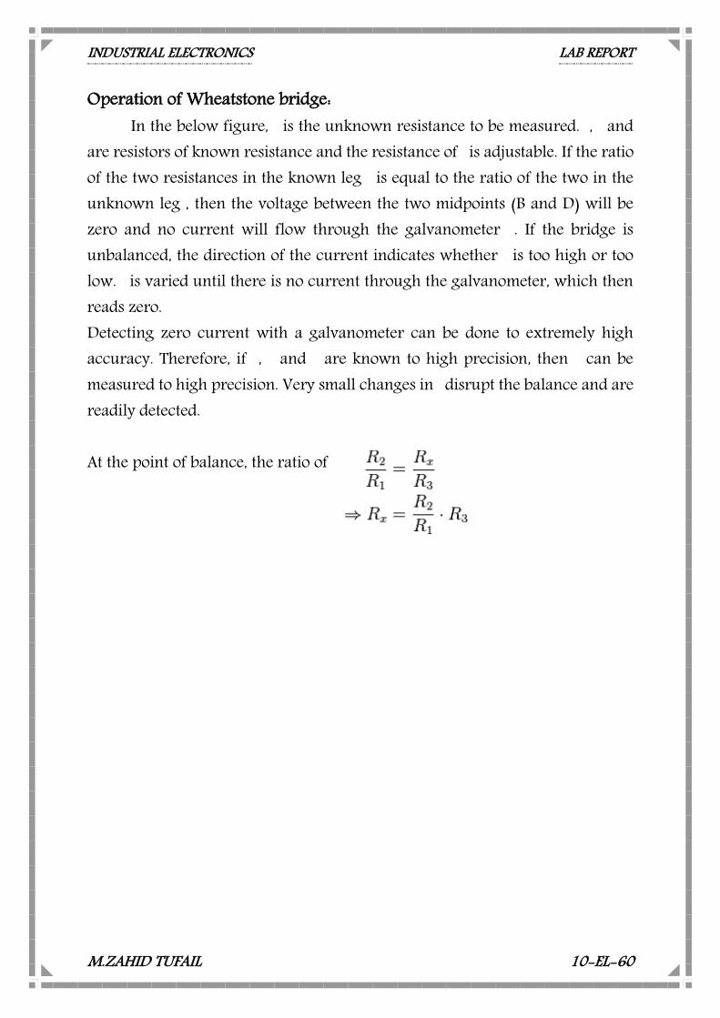
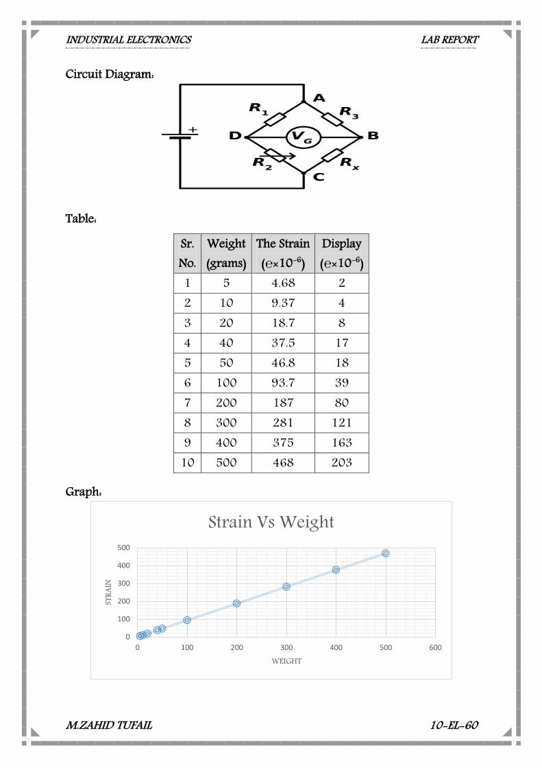
Operation of Wheatstone bridge: In the below figure, is the unknown resistance to be measured. , and
are resistors of known resistance and the resistance of is adjustable. If the ratio of the two resistances in the known leg is equal to the ratio of the two in the unknown leg , then the voltage between the two midpoints (B and D) will be zero and no current will flow through the galvanometer . If the bridge is unbalanced, the direction of the current indicates whether is too high or too low. is varied until there is no current through the galvanometer, which then reads zero. Detecting zero current with a galvanometer can be done to extremely high accuracy. Therefore, if , and are known to high precision, then can be measured to high precision. Very small changes in disrupt the balance and are readily detected. At the point of balance, the ratio of
INDUSTRIAL ELECTRONICS LAB REPORT
M.ZAHID TUFAIL 10-EL-60
Circuit Diagram:
Table: Graph:
0
100
200
300
400
500
0 100 200 300 400 500 600
STRA
IN
WEIGHT
Strain Vs Weight
Sr. No.
Weight (grams)
The Strain (×10-6)
Display (×10-6)
1 5 4.68 2 2 10 9.37 4 3 20 18.7 8 4 40 37.5 17 5 50 46.8 18 6 100 93.7 39 7 200 187 80 8 300 281 121 9 400 375 163
10 500 468 203
INDUSTRIAL ELECTRONICS LAB REPORT
M.ZAHID TUFAIL 10-EL-60
LAB ASSIGNMENT No. 9 Perform and verify Operation & Principle of Optical Transducer
Equipment Required: ST 2301 with Power supply cord Multi Meter Connecting cords Optical Transducers :
The ST2301 Optical Transducers Trainer deals with 4 different types of Optical Transducers viz. 1. Photovoltaic Cell, 2. Photoconductive Cell, 3. PIN Photodiode, 4. Phototransistor.
Photonic transducers convert light energy into a proportional
electrical output. The transduction mechanisms made use of in different t y pes of photonic transducers include photo-emissive effect, photoconductive effect, photovoltaic effect and pyro electric effect.
Accruing to the photo emissive effect, electrons are emitted from surface of a material on absorption of light energy in the form of photons. When the energy of an impinging photon is greater that the work function of the material, the photon liberates an electron wit h a kinetic energy equal to the difference between the photonic energy and the work function. This effect is used in vacuum and gas filled phototubes where photons impinging on a photocathode liberate electrons which are attracted towards the anode due to anode - cathode electric field, thus producing anode current proportional to light energy . The famous photomultiplier tube is based on photoemission and has provision for photo current multiplication.
INDUSTRIAL ELECTRONICS LAB REPORT
M.ZAHID TUFAIL 10-EL-60
In the photoconductive transducers, the input photon energy creates electron hole pairs, then increasing the number of available charge carriers and the conductivity of the semiconductor material of which they are made. They are made by depositing a thin film of Cadmium sulfide, Lead sulfide or lead solenoid on a ceramic substrate. Cadmium sulfide devices respond in the visible region, matching the response of a human eye. Lead sulfide & Lead solenoid detectors respond in 1 to 3 mm & 1 to6mm respectively.
Photovoltaic detectors are PN function based detectors. These junction
t y pe photo detectors more appropriately called photodiodes can also be operated in the photoconductive mode. In t he photovoltaic modes, the impinging photons generate electron-hole pairs in the depletion range. The electrons and holes respectively move towards N-side and P-side under the influence of the depletion field, leading to accumulation of charges on the two sides and consequently an open circuit voltage or a short circuit current that is proportional to light energy input.
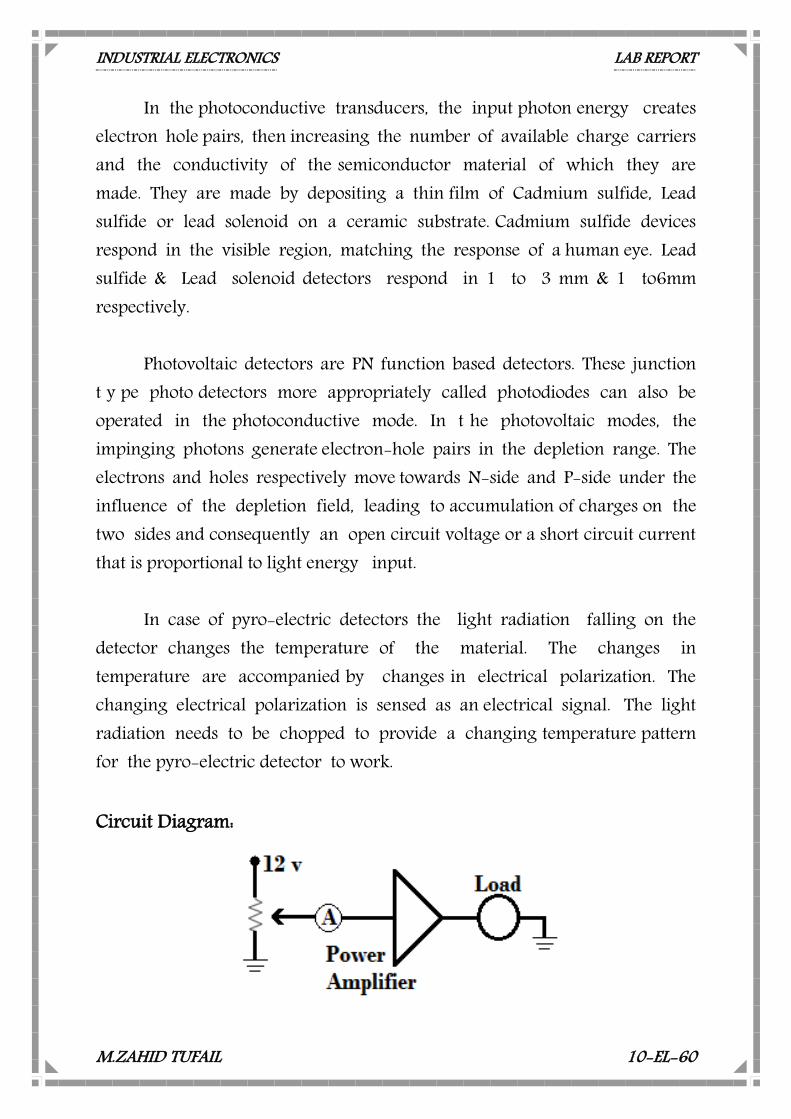
In case of pyro-electric detectors the light radiation falling on the
detector changes the temperature of the material. The changes in temperature are accompanied by changes in electrical polarization. The changing electrical polarization is sensed as an electrical signal. The light radiation needs to be chopped to provide a changing temperature pattern for the pyro-electric detector to work. Circuit Diagram:
INDUSTRIAL ELECTRONICS LAB REPORT
M.ZAHID TUFAIL 10-EL-60
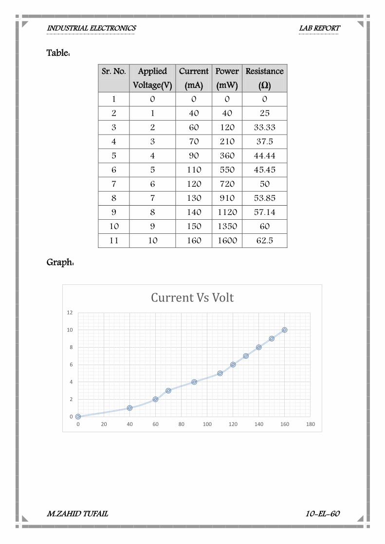
Table:
Graph:
0
2
4
6
8
10
12
0 20 40 60 80 100 120 140 160 180
Current Vs Volt
Sr. No. Applied Voltage(V)
Current (mA)
Power (mW)
Resistance (Ω)
1 0 0 0 0 2 1 40 40 25 3 2 60 120 33.33 4 3 70 210 37.5 5 4 90 360 44.44 6 5 110 550 45.45 7 6 120 720 50 8 7 130 910 53.85 9 8 140 1120 57.14
10 9 150 1350 60 11 10 160 1600 62.5
INDUSTRIAL ELECTRONICS LAB REPORT
M.ZAHID TUFAIL 10-EL-60
LAB ASSIGNMENT No. 10 Study the comparison between Lamp v/s Photovoltaic Cell Voltage
Equipment Required: ST 2301 with Power supply cord Multi Meter Connecting cords Optical Transducer:
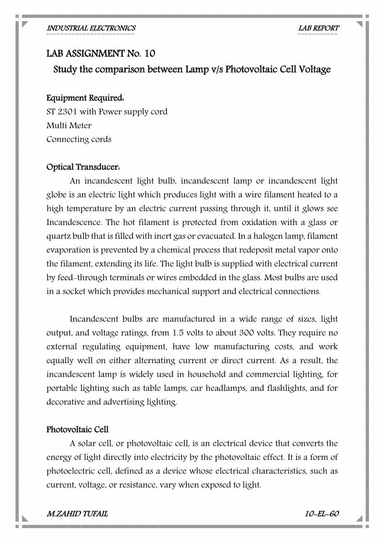
An incandescent light bulb, incandescent lamp or incandescent light globe is an electric light which produces light with a wire filament heated to a high temperature by an electric current passing through it, until it glows see Incandescence. The hot filament is protected from oxidation with a glass or quartz bulb that is filled with inert gas or evacuated. In a halogen lamp, filament evaporation is prevented by a chemical process that redeposit metal vapor onto the filament, extending its life. The light bulb is supplied with electrical current by feed-through terminals or wires embedded in the glass. Most bulbs are used in a socket which provides mechanical support and electrical connections.
Incandescent bulbs are manufactured in a wide range of sizes, light
output, and voltage ratings, from 1.5 volts to about 300 volts. They require no external regulating equipment, have low manufacturing costs, and work equally well on either alternating current or direct current. As a result, the incandescent lamp is widely used in household and commercial lighting, for portable lighting such as table lamps, car headlamps, and flashlights, and for decorative and advertising lighting. Photovoltaic Cell
A solar cell, or photovoltaic cell, is an electrical device that converts the energy of light directly into electricity by the photovoltaic effect. It is a form of photoelectric cell, defined as a device whose electrical characteristics, such as current, voltage, or resistance, vary when exposed to light.
INDUSTRIAL ELECTRONICS LAB REPORT
M.ZAHID TUFAIL 10-EL-60
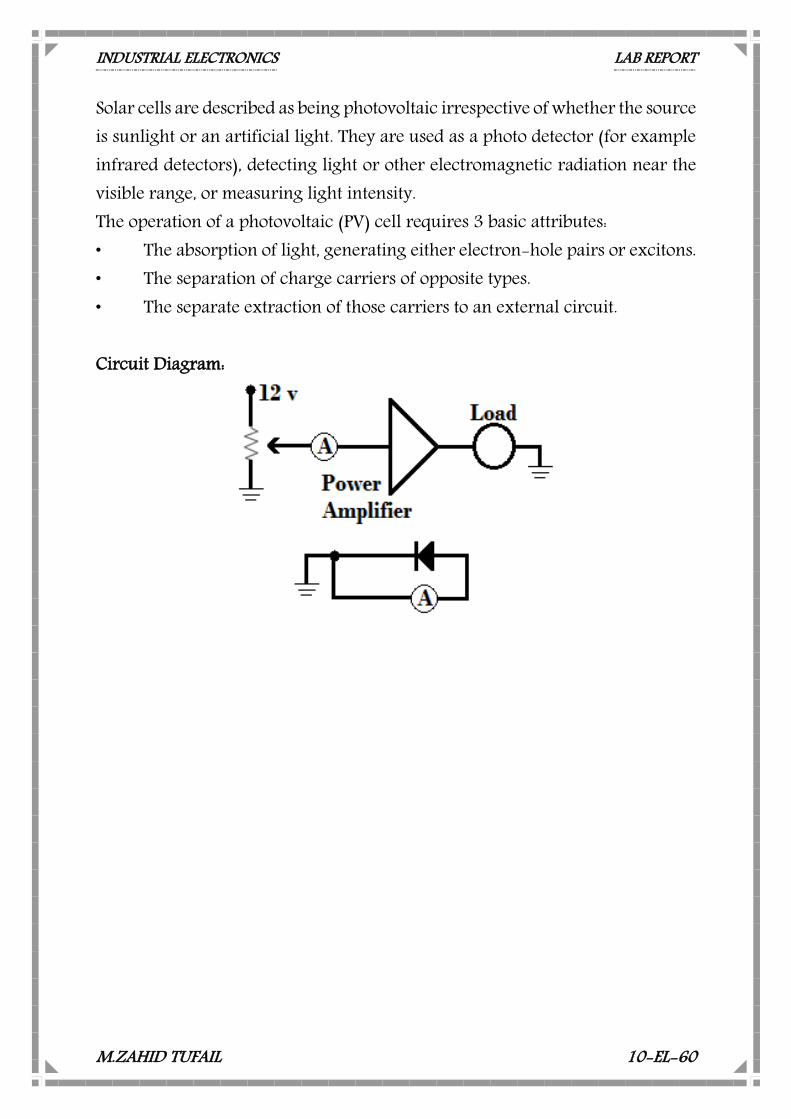
Solar cells are described as being photovoltaic irrespective of whether the source is sunlight or an artificial light. They are used as a photo detector (for example infrared detectors), detecting light or other electromagnetic radiation near the visible range, or measuring light intensity. The operation of a photovoltaic (PV) cell requires 3 basic attributes: • The absorption of light, generating either electron-hole pairs or excitons. • The separation of charge carriers of opposite types. • The separate extraction of those carriers to an external circuit. Circuit Diagram:
INDUSTRIAL ELECTRONICS LAB REPORT
M.ZAHID TUFAIL 10-EL-60
Table:
Graph:
0
10
20
30
40
50
60
70
80
0 2 4 6 8 10 12
CURR
ENT
VOLTAGE
Volt VS short circuit Current
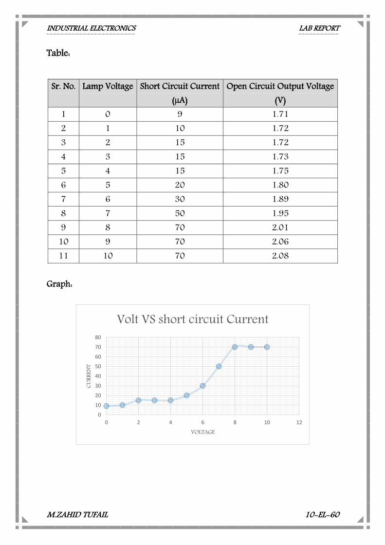
Sr. No. Lamp Voltage Short Circuit Current (µA)
Open Circuit Output Voltage (V)
1 0 9 1.71 2 1 10 1.72 3 2 15 1.72 4 3 15 1.73 5 4 15 1.75 6 5 20 1.80 7 6 30 1.89 8 7 50 1.95 9 8 70 2.01
10 9 70 2.06 11 10 70 2.08
INDUSTRIAL ELECTRONICS LAB REPORT
M.ZAHID TUFAIL 10-EL-60
LAB ASSIGNMENT No. 11 Study the comparison between Lamp v/s Photo Conductive Cell
Equipment Required: ST 2301 with Power supply cord Multi Meter Connecting cords Optical Transducer:
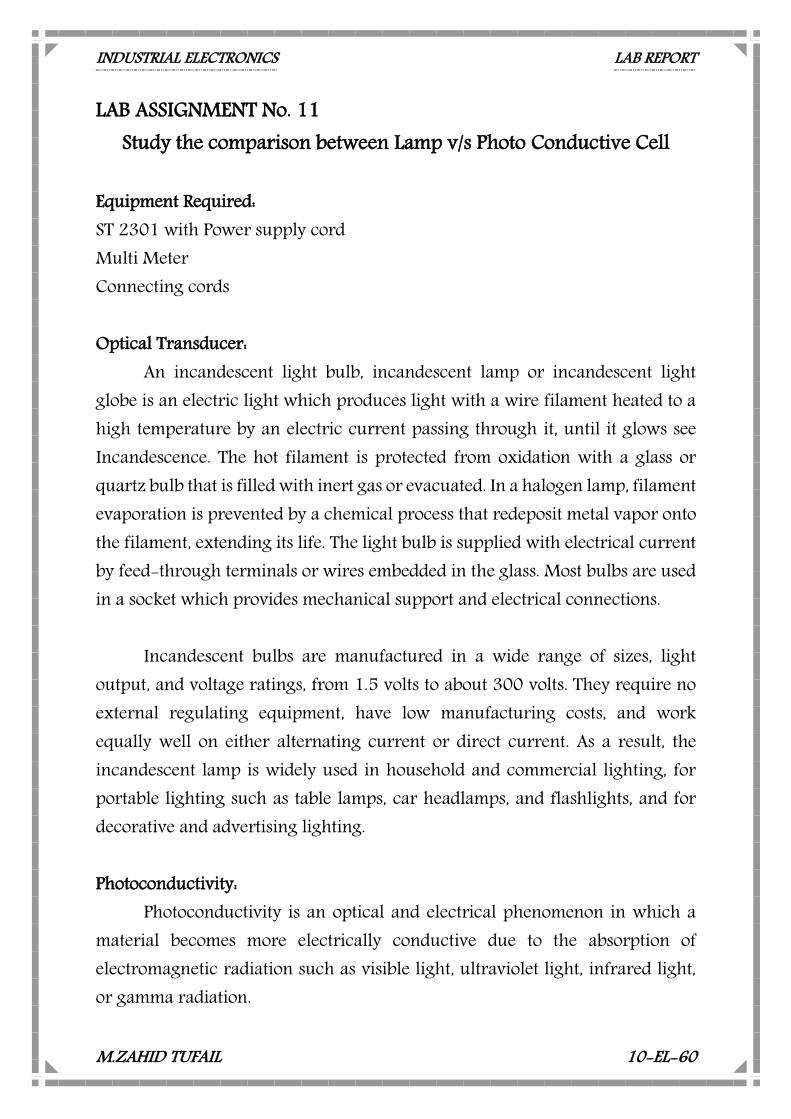
An incandescent light bulb, incandescent lamp or incandescent light globe is an electric light which produces light with a wire filament heated to a high temperature by an electric current passing through it, until it glows see Incandescence. The hot filament is protected from oxidation with a glass or quartz bulb that is filled with inert gas or evacuated. In a halogen lamp, filament evaporation is prevented by a chemical process that redeposit metal vapor onto the filament, extending its life. The light bulb is supplied with electrical current by feed-through terminals or wires embedded in the glass. Most bulbs are used in a socket which provides mechanical support and electrical connections.
Incandescent bulbs are manufactured in a wide range of sizes, light
output, and voltage ratings, from 1.5 volts to about 300 volts. They require no external regulating equipment, have low manufacturing costs, and work equally well on either alternating current or direct current. As a result, the incandescent lamp is widely used in household and commercial lighting, for portable lighting such as table lamps, car headlamps, and flashlights, and for decorative and advertising lighting. Photoconductivity:
Photoconductivity is an optical and electrical phenomenon in which a material becomes more electrically conductive due to the absorption of electromagnetic radiation such as visible light, ultraviolet light, infrared light, or gamma radiation.
INDUSTRIAL ELECTRONICS LAB REPORT
M.ZAHID TUFAIL 10-EL-60
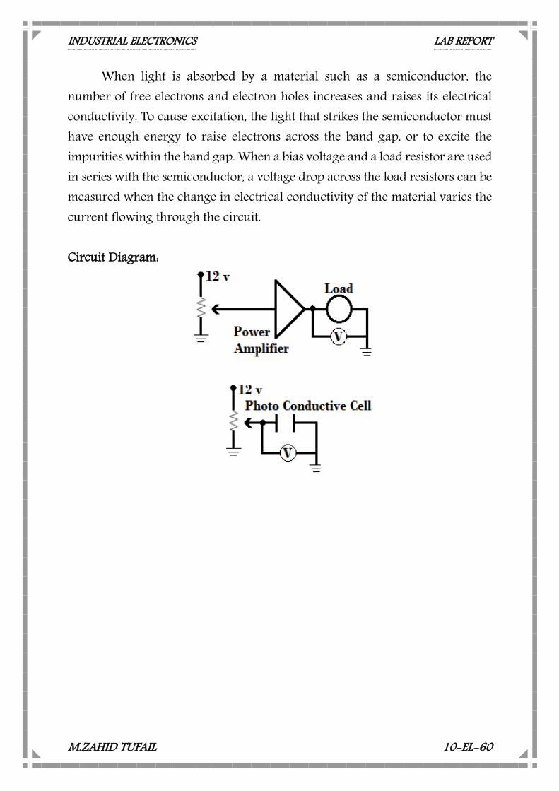
When light is absorbed by a material such as a semiconductor, the number of free electrons and electron holes increases and raises its electrical conductivity. To cause excitation, the light that strikes the semiconductor must have enough energy to raise electrons across the band gap, or to excite the impurities within the band gap. When a bias voltage and a load resistor are used in series with the semiconductor, a voltage drop across the load resistors can be measured when the change in electrical conductivity of the material varies the current flowing through the circuit. Circuit Diagram:
INDUSTRIAL ELECTRONICS LAB REPORT
M.ZAHID TUFAIL 10-EL-60
Table: Graph:
0
1
2
3
4
5
6
0 1 2 3 4 5 6
BULB
VOL
T
PHOTO CONDUCTIVE VOLT
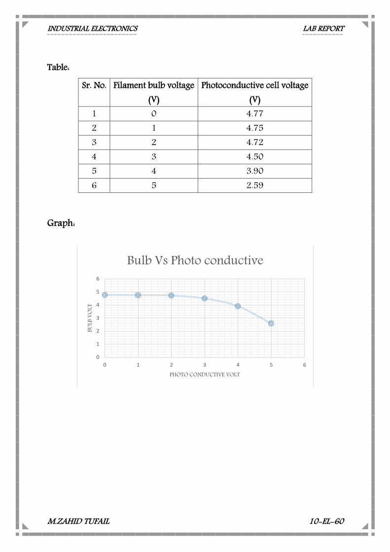
Bulb Vs Photo conductive
Sr. No. Filament bulb voltage (V)
Photoconductive cell voltage (V)
1 0 4.77 2 1 4.75 3 2 4.72 4 3 4.50 5 4 3.90 6 5 2.59
INDUSTRIAL ELECTRONICS LAB REPORT
M.ZAHID TUFAIL 10-EL-60
LAB ASSIGNMENT No. 12 Study the Input / Output Characteristics of LVDT
Equipment Required: ST 2301 with Power supply cord Multi Meter Connecting cords LVDT (Linear Variable Differential Transformer)
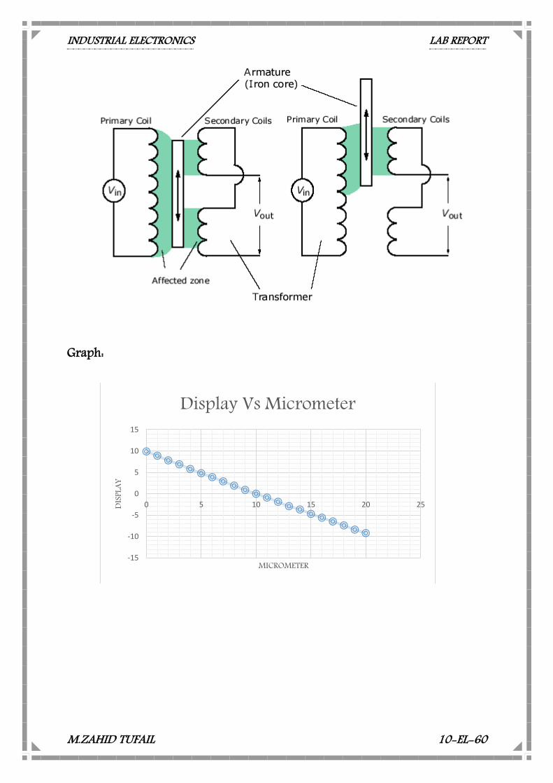
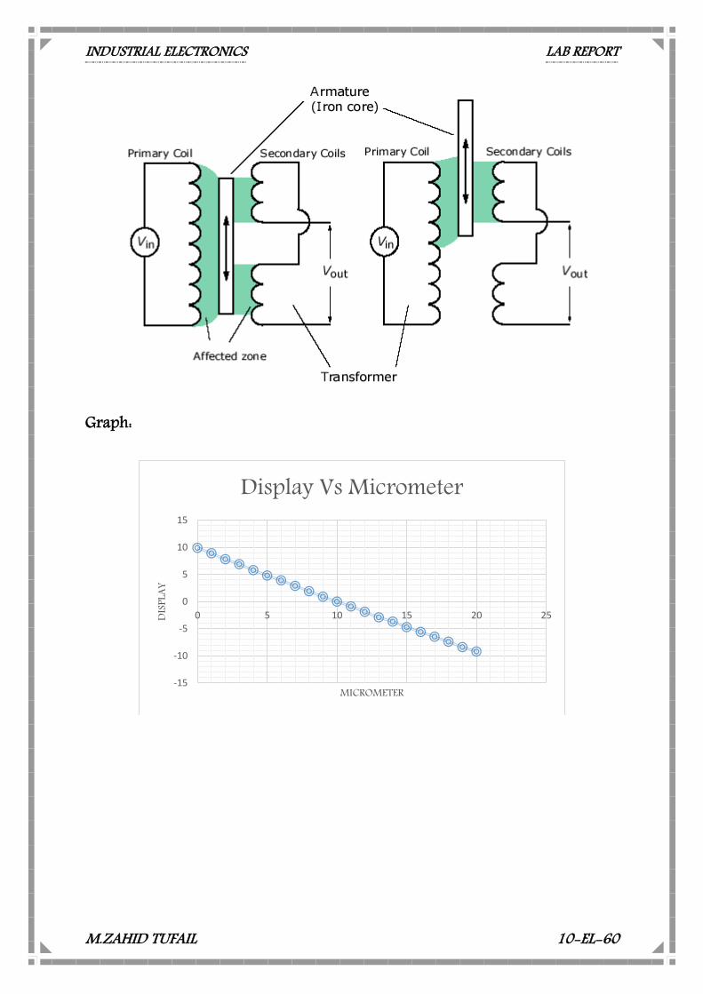
LVDT stands for Linear Variable Differential Transformer. It is most widely used inductive transducer that converts input displacement to an electrical signal. It consists of single primary winding and two secondary windings having equal number of turns and placed identically on either side of the primary winding. A movable soft iron core is placed inside a former upon which the windings are wound.
The primary is excited by an A.C voltage of frequency 50Hz to 20 KHz.
The secondary are connected in series opposing when the core is placed in the null position and the output voltage is zero as equal voltages induced in the secondary cancel each other. LVDT primary, secondary windings are connected such that applied voltage on primary and induced voltage on secondary are 180° phase opposition as shown in the figure.
If the core is moved to the left of null position more flux will link S1 than
that of S2. A resultant voltage (Es1 - Es2) which is in phase with primary voltage will appear across the output. If the core is moved to the right of null position, the resultant voltage (Es1 - Es2) is 180° out of phase with primary voltage which will be the output. Thus the output voltage is a measure of displacement.
INDUSTRIAL ELECTRONICS LAB REPORT
M.ZAHID TUFAIL 10-EL-60
Graph:
-15
-10
-5
0
5
10
15
0 5 10 15 20 25DISP
LAY
MICROMETER
Display Vs Micrometer
INDUSTRIAL ELECTRONICS LAB REPORT
M.ZAHID TUFAIL 10-EL-60
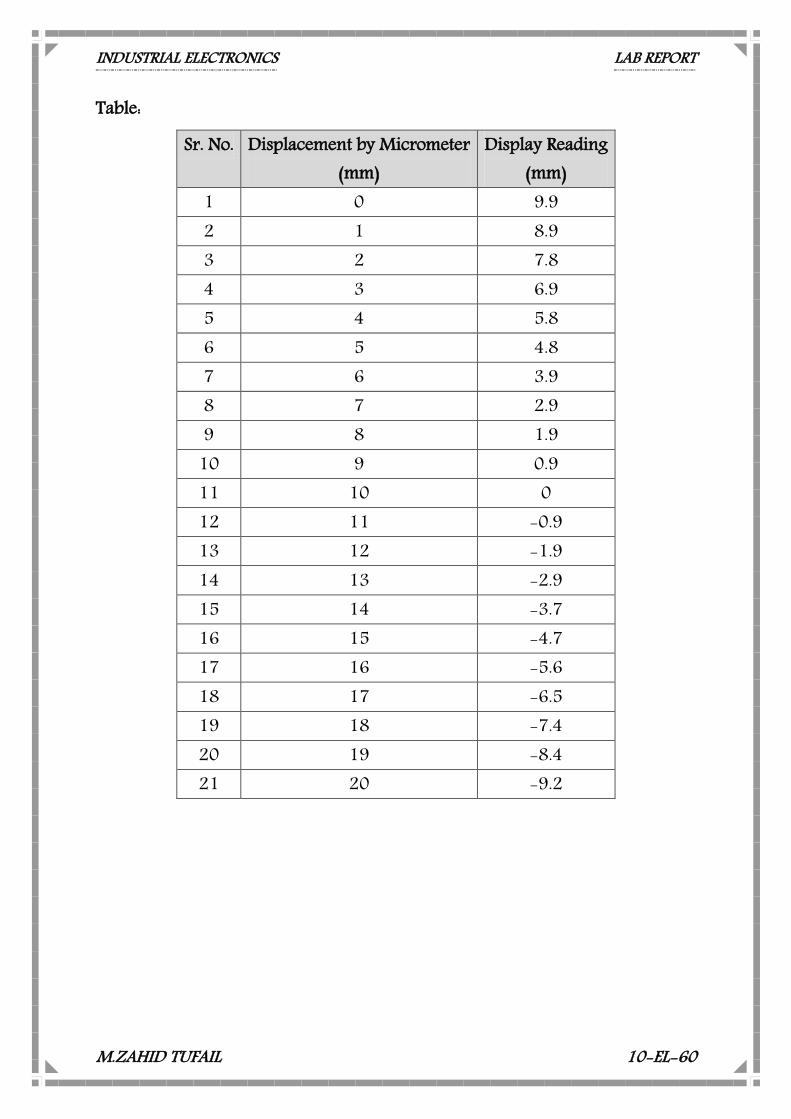
Table:
Sr. No. Displacement by Micrometer (mm)
Display Reading (mm)
1 0 9.9 2 1 8.9 3 2 7.8 4 3 6.9 5 4 5.8 6 5 4.8 7 6 3.9 8 7 2.9 9 8 1.9
10 9 0.9 11 10 0 12 11 -0.9 13 12 -1.9 14 13 -2.9 15 14 -3.7 16 15 -4.7 17 16 -5.6 18 17 -6.5 19 18 -7.4 20 19 -8.4 21 20 -9.2
INDUSTRIAL ELECTRONICS LAB REPORT
M.ZAHID TUFAIL 10-EL-60
LAB ASSIGNMENT No. 13 Study the Linear Range of Operation of LVDT
Equipment Required: ST 2301 with Power supply cord Multi Meter Connecting cords LVDT (Linear Variable Differential Transformer)
LVDT stands for Linear Variable Differential Transformer. It is most widely used inductive transducer that converts input displacement to an electrical signal. It consists of single primary winding and two secondary windings having equal number of turns and placed identically on either side of the primary winding. A movable soft iron core is placed inside a former upon which the windings are wound.
The primary is excited by an A.C voltage of frequency 50Hz to 20 KHz.
The secondary are connected in series opposing when the core is placed in the null position and the output voltage is zero as equal voltages induced in the secondary cancel each other. LVDT primary, secondary windings are connected such that applied voltage on primary and induced voltage on secondary are 180° phase opposition as shown in the figure.
If the core is moved to the left of null position more flux will link S1 than
that of S2. A resultant voltage (Es1 - Es2) which is in phase with primary voltage will appear across the output. If the core is moved to the right of null position, the resultant voltage (Es1 - Es2) is 180° out of phase with primary voltage which will be the output. Thus the output voltage is a measure of displacement.
INDUSTRIAL ELECTRONICS LAB REPORT
M.ZAHID TUFAIL 10-EL-60
Graph:
-15
-10
-5
0
5
10
15
0 5 10 15 20 25DISP
LAY
MICROMETER
Display Vs Micrometer
INDUSTRIAL ELECTRONICS LAB REPORT
M.ZAHID TUFAIL 10-EL-60
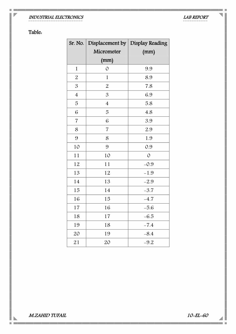
Table:
Sr. No. Displacement by Micrometer
(mm)
Display Reading (mm)
1 0 9.9 2 1 8.9 3 2 7.8 4 3 6.9 5 4 5.8 6 5 4.8 7 6 3.9 8 7 2.9 9 8 1.9
10 9 0.9 11 10 0 12 11 -0.9 13 12 -1.9 14 13 -2.9 15 14 -3.7 16 15 -4.7 17 16 -5.6 18 17 -6.5 19 18 -7.4 20 19 -8.4 21 20 -9.2
INDUSTRIAL ELECTRONICS LAB REPORT
M.ZAHID TUFAIL 10-EL-60
LAB ASSIGNMENT No. 14 Study the Operation and Principle of Optically
Controlled Switching System Equipment Required: ST 2301 with Power supply cord Multi Meter Connecting cords Optical Transducer:
An incandescent light bulb, incandescent lamp or incandescent light globe is an electric light which produces light with a wire filament heated to a high temperature by an electric current passing through it, until it glows see Incandescence. The hot filament is protected from oxidation with a glass or quartz bulb that is filled with inert gas or evacuated. In a halogen lamp, filament evaporation is prevented by a chemical process that redeposit metal vapor onto the filament, extending its life. The light bulb is supplied with electrical current by feed-through terminals or wires embedded in the glass. Most bulbs are used in a socket which provides mechanical support and electrical connections.
Incandescent bulbs are manufactured in a wide range of sizes, light
output, and voltage ratings, from 1.5 volts to about 300 volts. They require no external regulating equipment, have low manufacturing costs, and work equally well on either alternating current or direct current. As a result, the incandescent lamp is widely used in household and commercial lighting, for portable lighting such as table lamps, car headlamps, and flashlights, and for decorative and advertising lighting. Photoconductivity:
Photoconductivity is an optical and electrical phenomenon in which a material becomes more electrically conductive due to the absorption of
INDUSTRIAL ELECTRONICS LAB REPORT
M.ZAHID TUFAIL 10-EL-60
electromagnetic radiation such as visible light, ultraviolet light, infrared light, or gamma radiation.
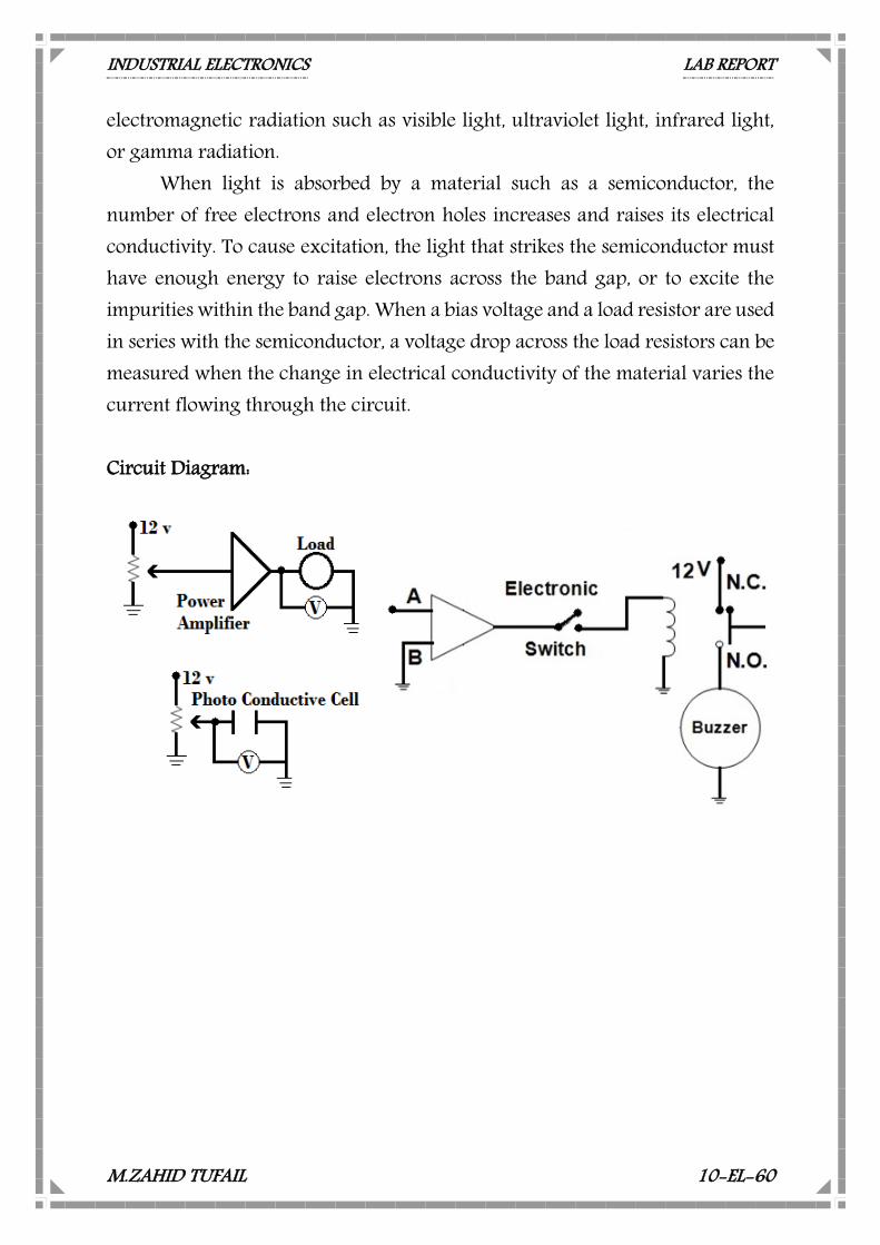
When light is absorbed by a material such as a semiconductor, the number of free electrons and electron holes increases and raises its electrical conductivity. To cause excitation, the light that strikes the semiconductor must have enough energy to raise electrons across the band gap, or to excite the impurities within the band gap. When a bias voltage and a load resistor are used in series with the semiconductor, a voltage drop across the load resistors can be measured when the change in electrical conductivity of the material varies the current flowing through the circuit. Circuit Diagram: