Embed Size (px)
Citation preview
Lab 8
Experiment 17 A Differentiator Circuit
Note Comment in Lab Manual
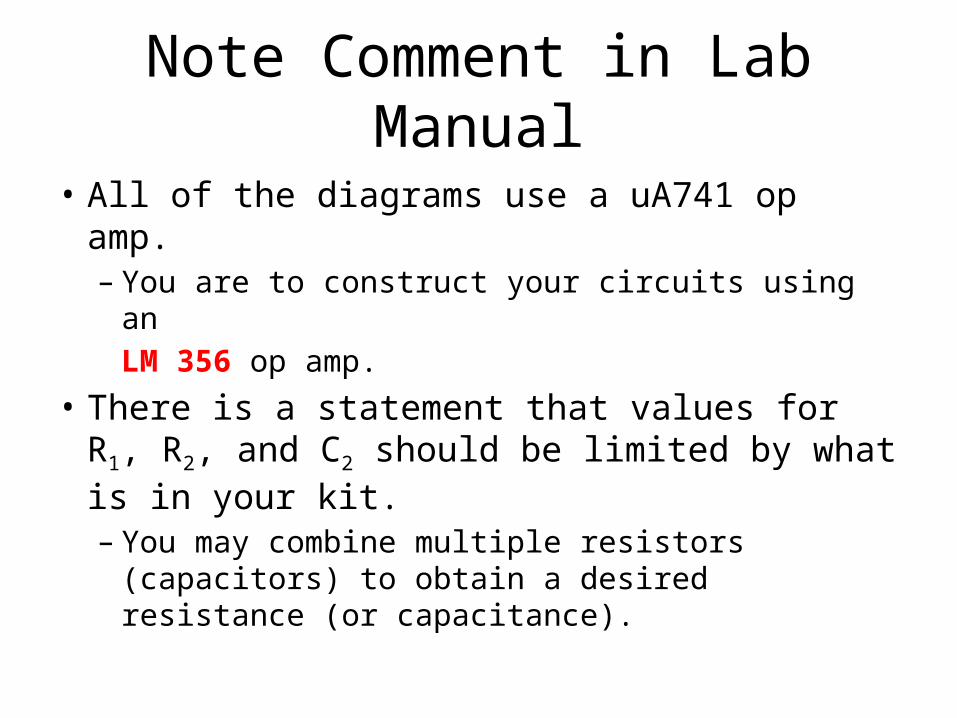
• All of the diagrams use a uA741 op amp.– You are to construct your circuits using an
LM 356 op amp.
• There is a statement that values for R1, R2, and C2 should be limited by what is in your kit.– You may combine multiple resistors (capacitors) to
obtain a desired resistance (or capacitance).
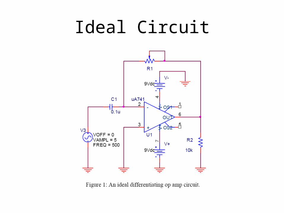
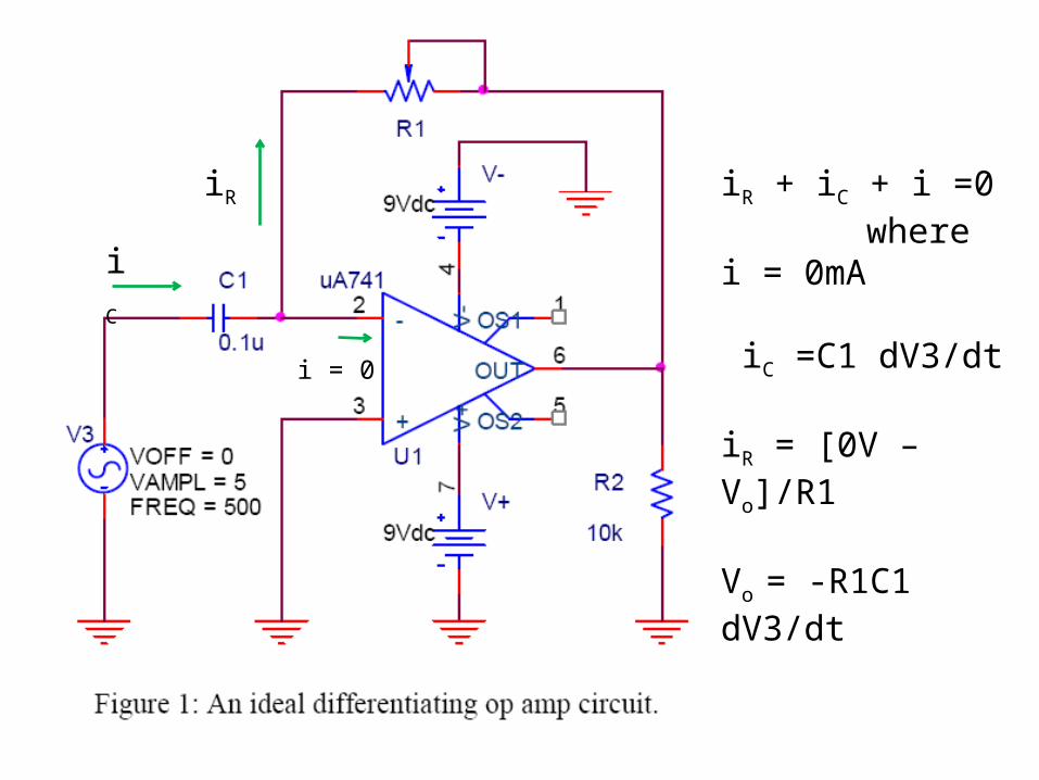
Ideal Circuit
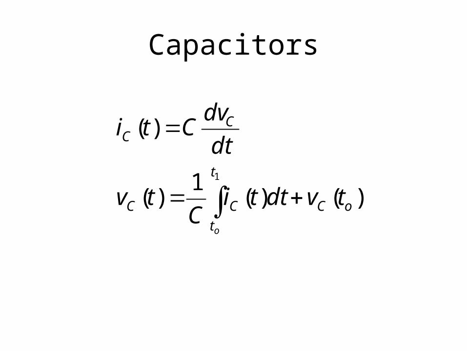
Capacitors
)()(1
)(
)(
1
oC
t
t
CC
CC
tvdttiC
tv
dt
dvCti
o
iC
i = 0
iR iR + iC + i =0 where i = 0mA
iC =C1 dV3/dt
iR = [0V – Vo]/R1
Vo = -R1C1 dV3/dt
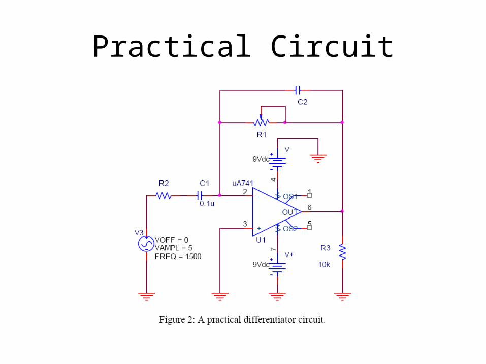
Practical Circuit
Why Two Different Circuits
• If the input contains electronic noise with high frequency components, the magnitude of the high frequency components will be amplified significantly over the signal of interest and the system likely will become unstable. – It is thus necessary to modify the circuit to reduce
or eliminate such effects.
Modifications to Ideal Circuit
• Two modifications to the circuit – both of which results in the formation of frequency filters. – First, a series resistor is inserted before the negative
input terminal of op amp. The effect of this resistor is to act as an attenuator for the high frequency components.
– Second, a capacitor is placed in the feedback network. This capacitor provides more feed-back for the high frequency components than for the low frequency components and also acts to stabilize the circuit.
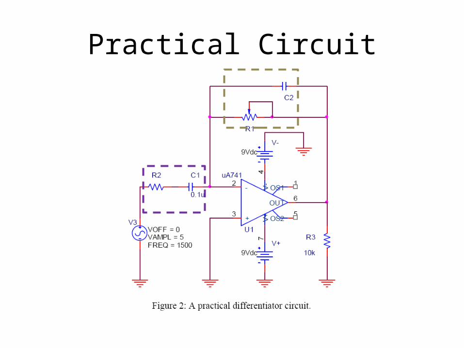
Practical Circuit

Capacitors
)()(1
)(
)(
1
oC
t
t
CC
CC
tvdttiC
tv
dt
dvCti
o
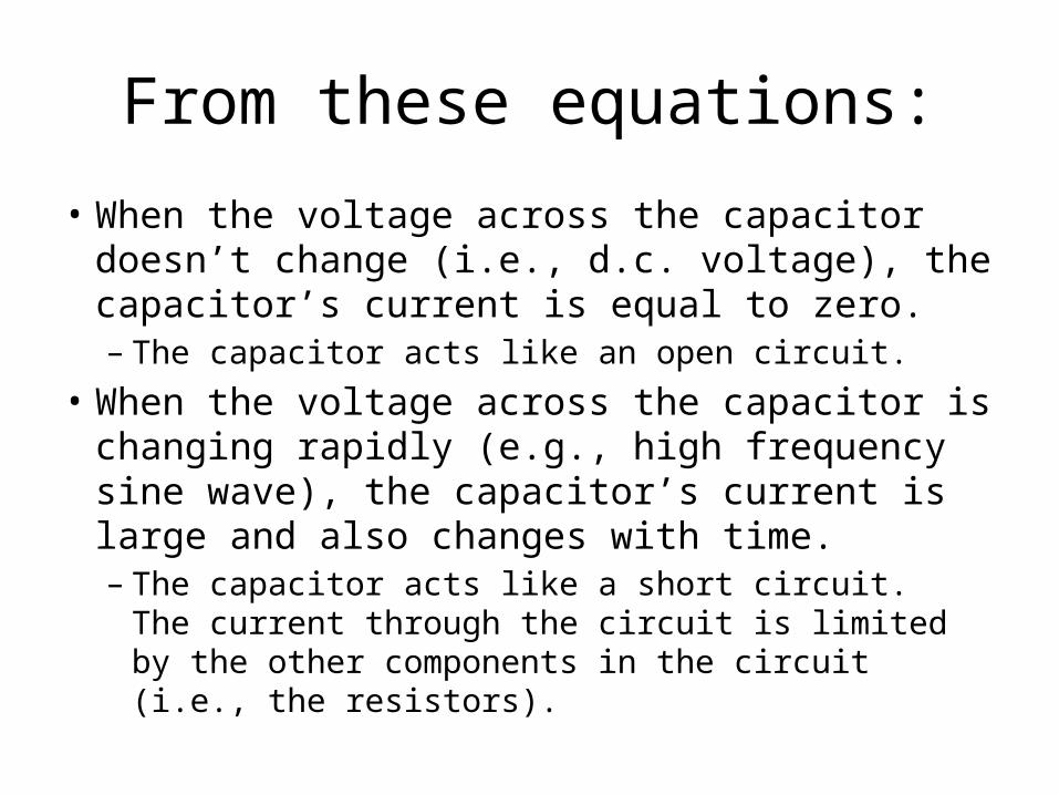
From these equations:
• When the voltage across the capacitor doesn’t change (i.e., d.c. voltage), the capacitor’s current is equal to zero.– The capacitor acts like an open circuit.
• When the voltage across the capacitor is changing rapidly (e.g., high frequency sine wave), the capacitor’s current is large and also changes with time.– The capacitor acts like a short circuit. The current
through the circuit is limited by the other components in the circuit (i.e., the resistors).
Practical Circuit
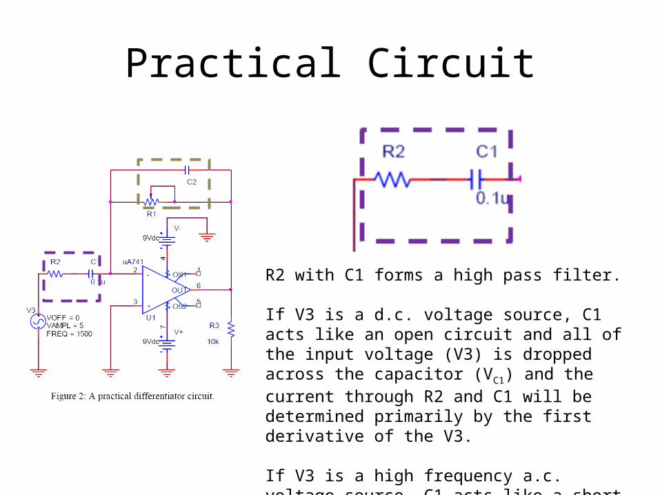
R2 with C1 forms a high pass filter.
If V3 is a d.c. voltage source, C1 acts like an open circuit and all of the input voltage (V3) is dropped across the capacitor (VC1) and the current through R2 and C1 will be determined primarily by the first derivative of the V3.
If V3 is a high frequency a.c. voltage source, C1 acts like a short circuit and the current through R2 and C1 will be determined primarily by V3 divided by R2.
Practical Circuit
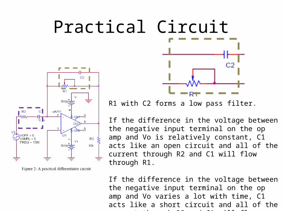
R1 with C2 forms a low pass filter.
If the difference in the voltage between the negative input terminal on the op amp and Vo is relatively constant, C1 acts like an open circuit and all of the current through R2 and C1 will flow through R1.
If the difference in the voltage between the negative input terminal on the op amp and Vo varies a lot with time, C1 acts like a short circuit and all of the current through R2 and C1 will flow through C2 and the output voltage will be approximately equal to the voltage on the negative input terminal, which will be 0 V.
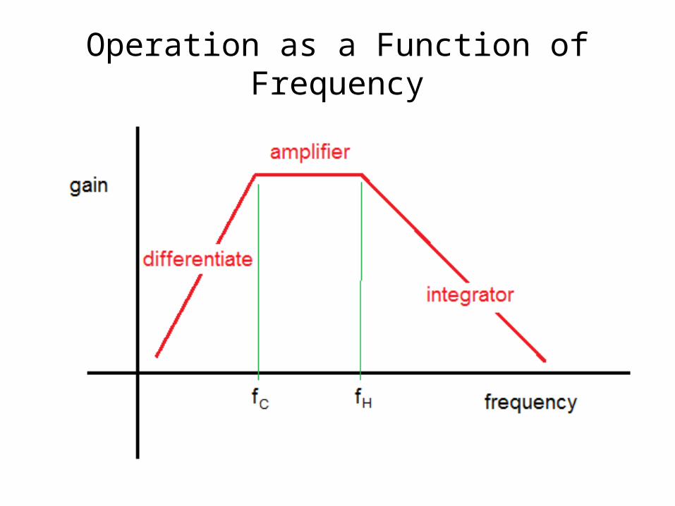
Operation as a Function of Frequency
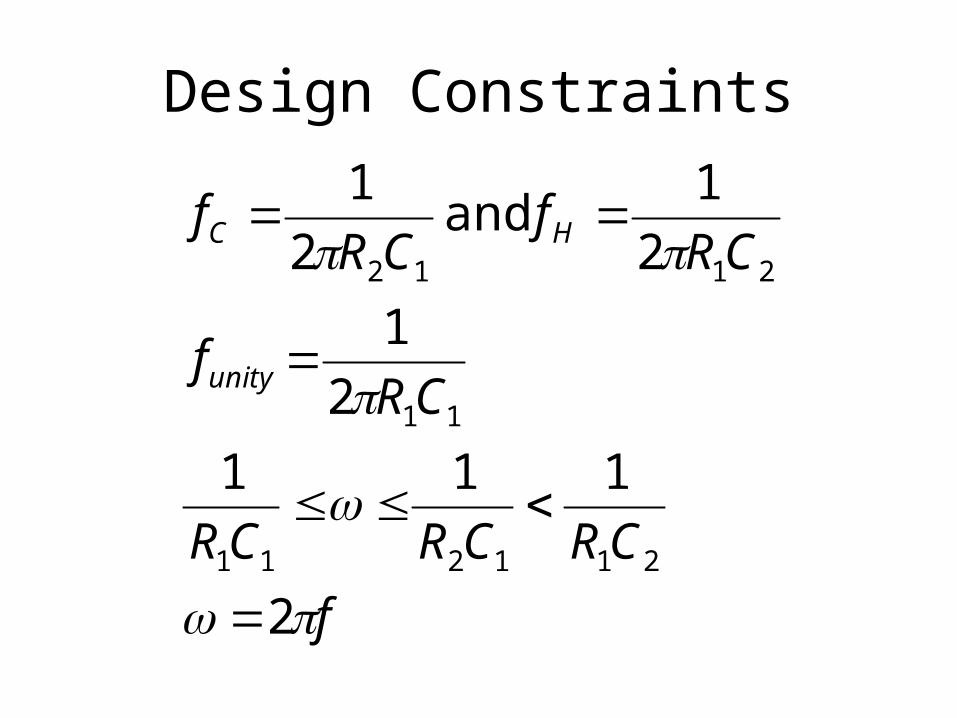
Design Constraints
f
CRCRCR
CRf
CRf
CRf
unity
HC
2
111
2
1
2
1 and
2
1
211211
11
2112
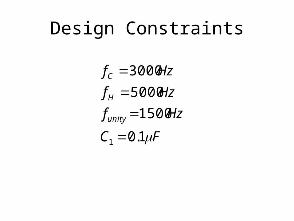
Design Constraints
FC
Hzf
Hzf
Hzf
unity
H
C
1.0
1500
5000
3000
1
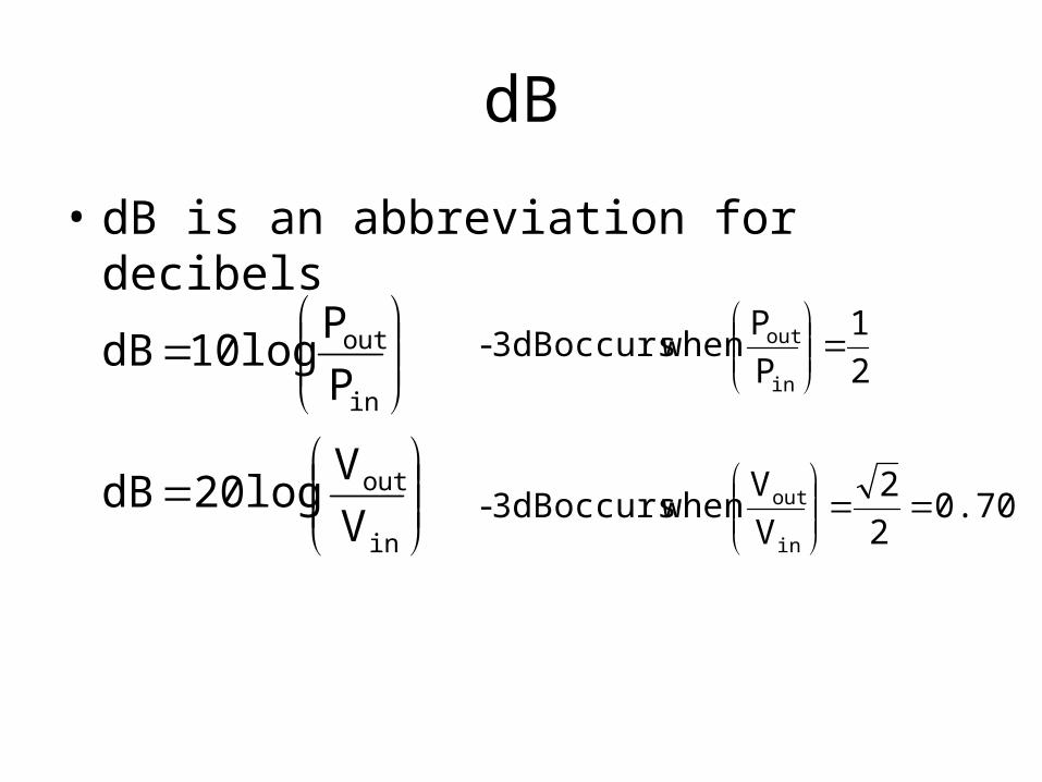
dB
• dB is an abbreviation for decibels
V
V log 20 dB
P
Plog 10 dB
in
out
in
out
0.707 2
2
V
V when occurs 3dB-
2
1
P
P when occurs 3dB-
in
out
in
out
Follow the Directions in the Lab Manual
• Except:– Use the function generator on the Velleman
oscilloscope• Remember that you have to set the Amplitude to 10V to
have 5V sin(wt) outputted.
– Do not use the 10X probes with the Velleman oscilloscope when performing the oscilloscope measurements.• Just use the standard BNC-to-alligator or BNC-to-IC clip
cables.
– All plots should be made using MatLAB.
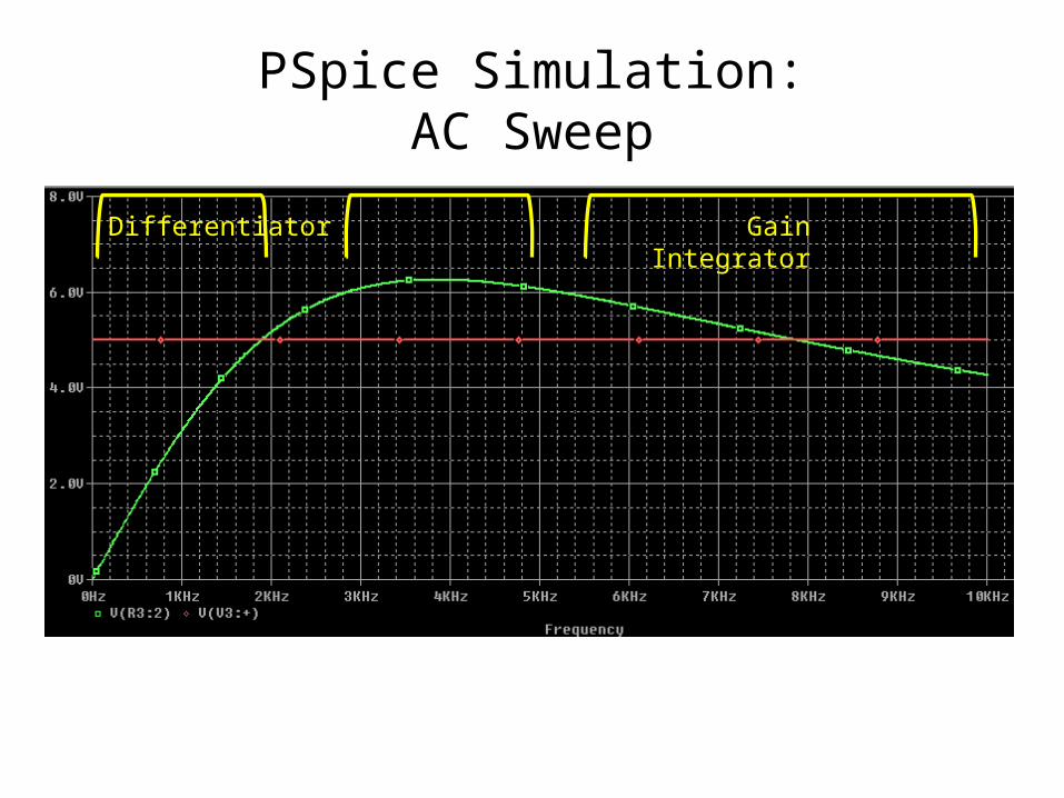
PSpice Simulation:AC Sweep
Differentiator Gain Integrator
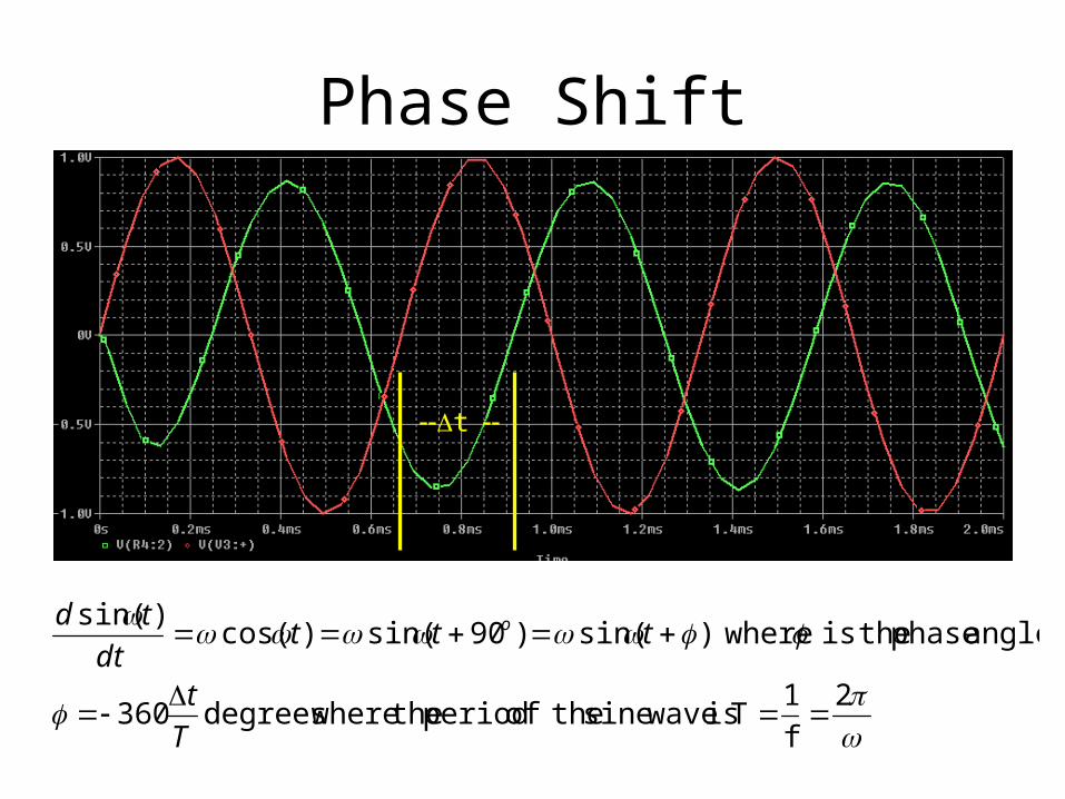
Phase Shift
--Dt --
2
f
1T is wavesine theof period the wheredegrees360
angle. phase theis where)sin( )90sin()cos()sin(
T
t
tttdt
td o
Phase Shift as a Function of Frequency
• The phase shift between the input voltage and the output voltage of the op amp will change from 90o to 180o to 270o as the operation of the circuit changes from a differentiator to inverting amplifier to integrator.
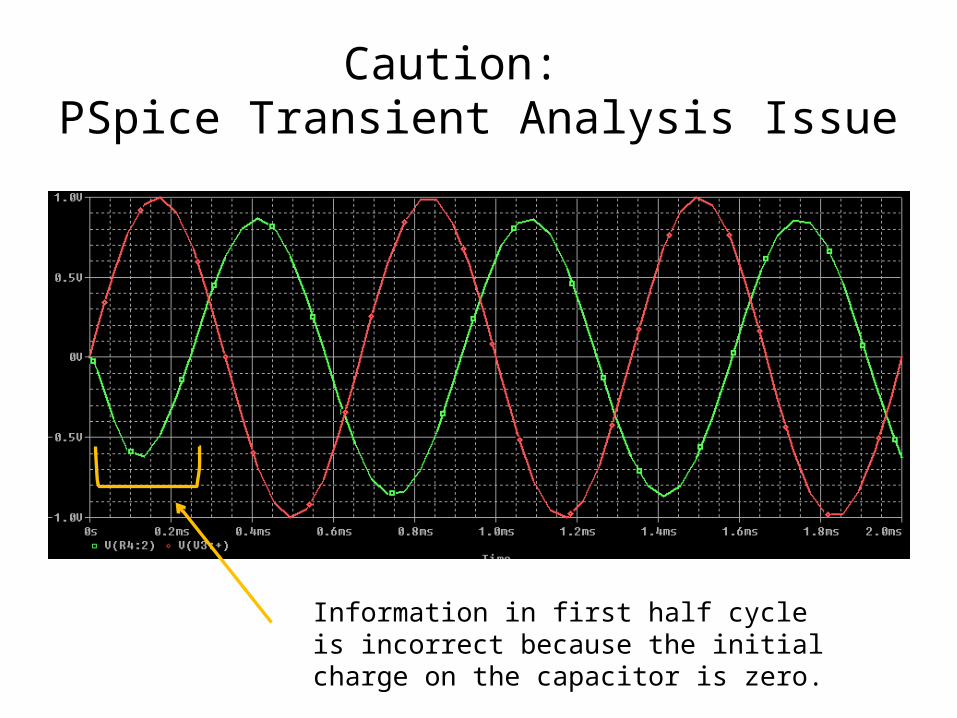
Caution: PSpice Transient Analysis Issue
Information in first half cycle is incorrect because the initial charge on the capacitor is zero.
Measurement of Phase Angle
• There are two sets of instructions in the Lab 8 folder under resources– Phase Delay.pdf, which explains how to make a phase
angle calculation using the information displayed when the Oscilloscope function of the Velleman oscilloscope is used.• You should become familiar with this technique.
– Magnitude and Phase.pdf, which explains how to use the automated measurement tools on the Velleman scope to obtain the magnitude and phase of a signal at a single frequency and over a range of frequencies.