Embed Size (px)
Citation preview
P309 Intermediate Lab, Indiana University Dept. of Physics
Last revised by Mike Hosek, Sunny Nigam and James A. Glazier 9/10/15
1
Lab #3: Operational Amplifiers
Goal: So far we have looked at passive circuits composed of resistors, capacitors and
inductors. The problem with passive circuits is that the real part of the impedance always
decreases the amplitude of voltage and current in the circuit. Often we wish to take a small
voltage or current and amplify it, so that we can measure it with greater precision. We might
also want to add, subtract, multiply, divide, integrate or differentiate two or more voltage
or current amplitudes. Amplifiers allow us to perform all of these mathematical operations
and more on an AC or DC voltage or current. The operational amplifier (op-amp) is a
particular type of integrated circuit amplifier with standard properties that makes
implementing these functions particularly simple. In this laboratory, you will learn the
basic properties of an ideal op-amp, how to use operational amplifiers with various types
of feedback control to perform simple transformations of an input signal and also some of
the limitations of real op-amps. You will also apply the integrator circuit to measure the
amplitude and direction of earth’s magnetic field in the laboratory. For a good primer on
op-amps, see Wikipedia (https://en.wikipedia.org/wiki/Operational_amplifier).
Equipment: OP07 op-amp, proto-board, assorted resistors and capacitors, DMM,
oscilloscope, large inductor coil.
1 Introduction:
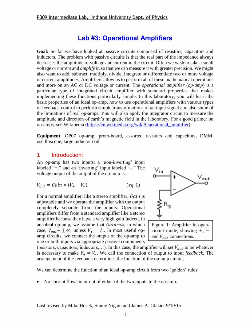
An op-amp has two inputs: a ‘non-inverting’ input
labeled “+,” and an ‘inverting’ input labeled “–.” The
voltage output of the output of the op-amp is:
𝑉𝑜𝑢𝑡 = 𝐺𝑎𝑖𝑛 × (𝑉+ − 𝑉−). (𝑒𝑞. 1)
For a normal amplifier, like a stereo amplifier, 𝐺𝑎𝑖𝑛 is
adjustable and we operate the amplifier with the output
completely separate from the inputs. Operational
amplifiers differ from a standard amplifier like a stereo
amplifier because they have a very high gain Indeed, in
an ideal op-amp, we assume that 𝐺𝑎𝑖𝑛~∞, in which
case, 𝑉𝑜𝑢𝑡~±∞, unless 𝑉+ = 𝑉−. In most useful op-
amp circuits, we connect the output of the op-amp to
one or both inputs via appropriate passive components
(resistors, capacitors, inductors,…). In this case, the amplifier will set 𝑉𝑜𝑢𝑡 to be whatever
is necessary to make 𝑉+ = 𝑉−. We call the connection of output to input feedback. The
arrangement of the feedback determines the function of the op-amp circuit.
We can determine the function of an ideal op-amp circuit from two ‘golden’ rules:
No current flows in or out of either of the two inputs to the op-amp.
Figure 1: Amplifier in open-
circuit mode, showing +, −
and 𝑉𝑜𝑢𝑡 connections.
P309 Intermediate Lab, Indiana University Dept. of Physics
Last revised by Mike Hosek, Sunny Nigam and James A. Glazier 9/10/15
2
𝑉𝑜𝑢𝑡 in any feedback scenario strives to make the voltage difference between the two
inputs zero 𝑉+ = 𝑉−.
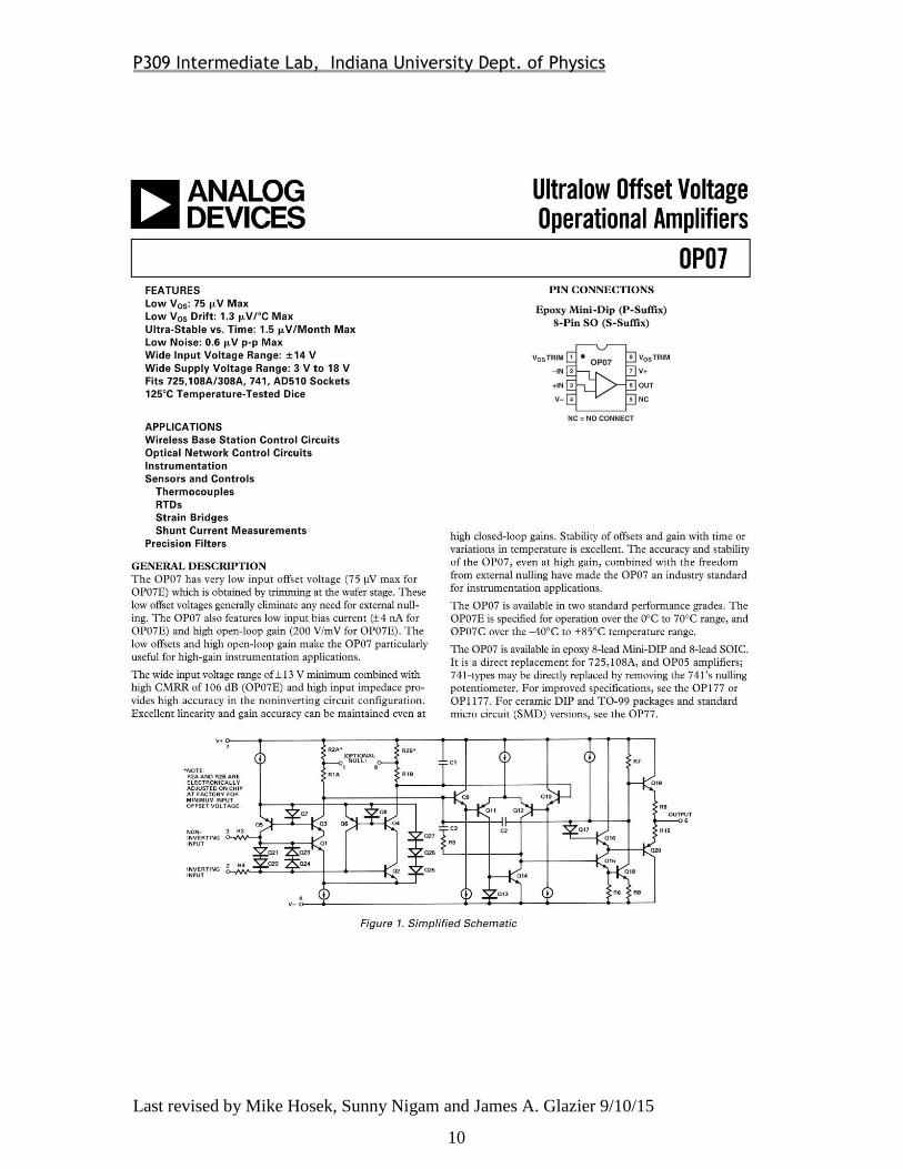
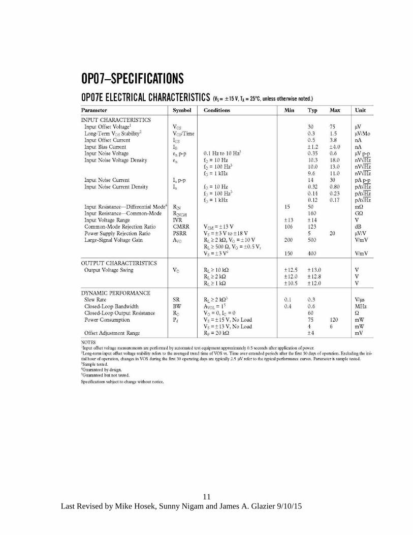
Our op-amp is an OP07, an integrated circuit with dozens of transistors, packaged in an 8-
pin plastic DIP (Dual In-Line Package). You will find a data sheet for the OP07 at the end
of this document. Unlike the other components you have studied so far, the op-amp is an
active device: it requires a power supply to operate. The OP07 op-amp requires power-
supply voltages of ±15 V. If the output wants to exceed the supply voltage, the signal is
‘clipped,’ i.e., if equation 1 predicts 𝑉𝑜𝑢𝑡 > 15V, then the actual 𝑉𝑜𝑢𝑡 = 15V, and if
equation 1 predicts 𝑉𝑜𝑢𝑡 < −15V, then the actual 𝑉𝑜𝑢𝑡 = −15V. Clipping is one of the
differences between a real and an ideal op-amp.
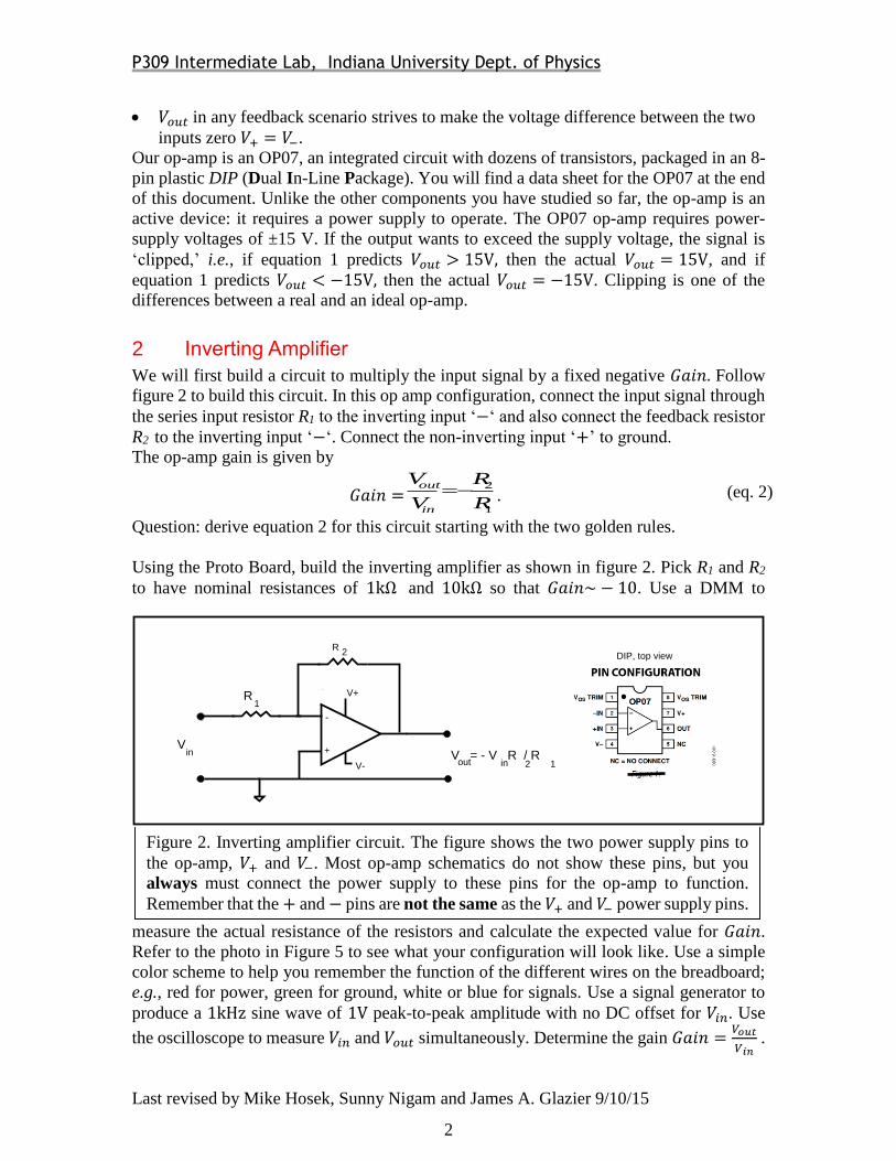
2 Inverting Amplifier
We will first build a circuit to multiply the input signal by a fixed negative 𝐺𝑎𝑖𝑛. Follow
figure 2 to build this circuit. In this op amp configuration, connect the input signal through
the series input resistor R1 to the inverting input ‘−‘ and also connect the feedback resistor
R2 to the inverting input ‘−‘. Connect the non-inverting input ‘+’ to ground.
The op-amp gain is given by
𝐺𝑎𝑖𝑛 =1
2
R
R
V
V
in
out . (eq. 2)
Question: derive equation 2 for this circuit starting with the two golden rules.
Using the Proto Board, build the inverting amplifier as shown in figure 2. Pick R1 and R2
to have nominal resistances of 1kΩ and 10kΩ so that 𝐺𝑎𝑖𝑛~ − 10. Use a DMM to
measure the actual resistance of the resistors and calculate the expected value for 𝐺𝑎𝑖𝑛.
Refer to the photo in Figure 5 to see what your configuration will look like. Use a simple
color scheme to help you remember the function of the different wires on the breadboard;
e.g., red for power, green for ground, white or blue for signals. Use a signal generator to
produce a 1kHz sine wave of 1V peak-to-peak amplitude with no DC offset for 𝑉𝑖𝑛. Use
the oscilloscope to measure 𝑉𝑖𝑛 and 𝑉𝑜𝑢𝑡 simultaneously. Determine the gain 𝐺𝑎𝑖𝑛 =𝑉𝑜𝑢𝑡
𝑉𝑖𝑛 .
Figure 2. Inverting amplifier circuit. The figure shows the two power supply pins to
the op-amp, 𝑉+ and 𝑉−. Most op-amp schematics do not show these pins, but you
always must connect the power supply to these pins for the op-amp to function.
Remember that the + and − pins are not the same as the 𝑉+ and 𝑉− power supply pins.
-
+
_
R
V+
V-
DIP, top view
V
R
V = - V R / R
1
out 12inin
2
P309 Intermediate Lab, Indiana University Dept. of Physics
Last revised by Mike Hosek, Sunny Nigam and James A. Glazier 9/10/15
3
Questions: Compare your measured 𝐺𝑎𝑖𝑛 to the theoretical value 𝐺𝑎𝑖𝑛𝑡ℎ𝑒𝑜𝑟𝑒𝑡𝑖𝑐𝑎𝑙 = −𝑅2
𝑅1.
Change the frequency of the function generator to 100Hz and 10kHz and measure the gain
again. Is the gain independent of frequency? Change the input peak-to-peak voltage to
0.1V, 0.2V, 0.5V and 1.5V. Is 𝐺𝑎𝑖𝑛 independent of the input voltage (i.e. is the amplifier
linear)?
Increase the signal generator amplitude until you observe clipping of 𝑉𝑜𝑢𝑡. At what output
voltage do you see clipping?
An ideal op-amp has an output voltage that changes instantly as the input voltage changes.
A real op-amp has a maximum change in output voltage/second called the slew rate.
Estimate the slew rate of your op-amp by setting the function generator to produce a square
wave signal. Display both the square wave input voltage and the output voltage on the
oscilloscope. Increase the frequency of the signal until the two traces are clearly different.
Bow sketch or record the traces and measure the maximum 𝑑𝑉
𝑑𝑡 for the op-amp. Compare
this result to the slew-rate quoted in the data sheet for the op-amp.
Question—How can the finite slew rate of an op-amp affect its function? Suppose you had
a sine-wave input signal to the op-amp of a fixed peak-to-peak amplitude, 𝑉𝑖𝑛 =𝑉𝑝−𝑝
2sin (𝜔𝑡). Calculate the theoretical output voltage of the op-amp circuit as a function
of the 𝐺𝑎𝑖𝑛, the slew rate, 𝑉𝑝−𝑝 and 𝜔. Repeat your experiment with a sine-wave input for
three different 𝑉𝑝−𝑝 (𝑉𝑝−𝑝
10, 𝑉𝑝−𝑝 𝑎𝑛𝑑 10 𝑉𝑝−𝑝). For each 𝑉𝑝−𝑝 sweep the frequency in
powers of 10 and measure the output peak-to-peak voltage. Compare your results to your
theoretical calculation.
For an ideal op-amp, 𝑉𝑜𝑢𝑡 = 0V if 𝑉+ = 𝑉−. A real op-amp, will have 𝑉𝑜𝑢𝑡 = a small offset
voltage 𝑉𝑂𝑆, when 𝑉+ = 𝑉−. Measure the offset voltage of the OP07. Use the circuit in
Figure 2, and pick R1 and R2 to have nominal resistances of 10Ω and 10kΩ so that
𝐺𝑎𝑖𝑛~ − 1000. As usual, measure both 𝑅1 and 𝑅2 to calculate 𝐺𝑎𝑖𝑛𝑡ℎ𝑒𝑜𝑟𝑒𝑡𝑖𝑐𝑎𝑙. Connect
𝑉− to ground to set 𝑉𝑖𝑛 = 0V. Now measure 𝑉𝑜𝑢𝑡with a DMM.
Question: Consider R1 and R2 as a voltage divider. What is 𝑉−? Compare the measured
offset voltage with 𝑉𝑂𝑆 specified in the OP07 data sheet.
3 Non-inverting Amplifier
What if we don’t want to have the output voltage inverted with respect to the input voltage?
Build the non-inverting linear amplifier circuit in Figure 3. Here the input voltage connects
to the non-inverting input and the voltage divider returns a fraction of the output voltage to
the inverting input. Use the same resistors that you used in Section 2 for a nominal
𝐺𝑎𝑖𝑛~ − 10 to construct the circuit. Measure Vin and Vout, determine the actual gain.
Question: Using the golden rules for op-amps show that the theoretical value for the gain
of this circuit is:
P309 Intermediate Lab, Indiana University Dept. of Physics
Last revised by Mike Hosek, Sunny Nigam and James A. Glazier 9/10/15
4
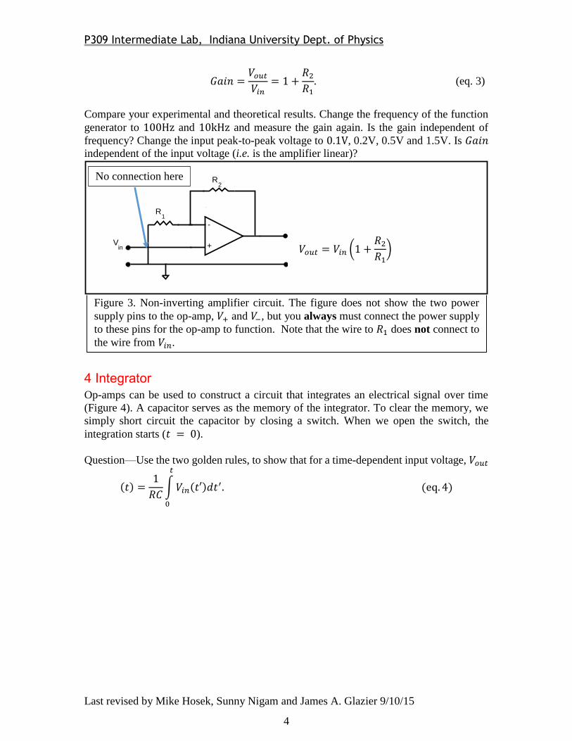
𝐺𝑎𝑖𝑛 =𝑉𝑜𝑢𝑡𝑉𝑖𝑛
= 1 +𝑅2
𝑅1. (eq. 3)
Compare your experimental and theoretical results. Change the frequency of the function
generator to 100Hz and 10kHz and measure the gain again. Is the gain independent of
frequency? Change the input peak-to-peak voltage to 0.1V, 0.2V, 0.5V and 1.5V. Is 𝐺𝑎𝑖𝑛
independent of the input voltage (i.e. is the amplifier linear)?
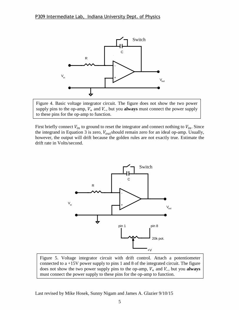
4 Integrator
Op-amps can be used to construct a circuit that integrates an electrical signal over time
(Figure 4). A capacitor serves as the memory of the integrator. To clear the memory, we
simply short circuit the capacitor by closing a switch. When we open the switch, the
integration starts (𝑡 = 0).
Question—Use the two golden rules, to show that for a time-dependent input voltage, 𝑉𝑜𝑢𝑡
(𝑡) =1
𝑅𝐶∫𝑉𝑖𝑛(𝑡′)𝑑𝑡
′.
𝑡
0
(eq. 4)
Figure 3. Non-inverting amplifier circuit. The figure does not show the two power
supply pins to the op-amp, 𝑉+ and 𝑉−, but you always must connect the power supply
to these pins for the op-amp to function. Note that the wire to 𝑅1 does not connect to
the wire from 𝑉𝑖𝑛.
-
+
_
V
R
R
V = V (1 + R / R )out in 12
1
2
in 𝑉𝑜𝑢𝑡 = 𝑉𝑖𝑛 1 +𝑅2
𝑅1
No connection here
P309 Intermediate Lab, Indiana University Dept. of Physics
Last revised by Mike Hosek, Sunny Nigam and James A. Glazier 9/10/15
5
First briefly connect 𝑉𝑖𝑛 to ground to reset the integrator and connect nothing to 𝑉𝑖𝑛. Since
the integrand in Equation 3 is zero, 𝑉𝑜𝑢𝑡should remain zero for an ideal op-amp. Usually,
however, the output will drift because the golden rules are not exactly true. Estimate the
drift rate in Volts/second.
-
+
_
VV
in
out
R
C
pin 1 pin 8
20k pot.
+V
V0
+V
R
R0
1
Figure 5. Voltage integrator circuit with drift control. Attach a potentiometer
connected to a +15V power supply to pins 1 and 8 of the integrated circuit. The figure
does not show the two power supply pins to the op-amp, 𝑉+ and 𝑉−, but you always
must connect the power supply to these pins for the op-amp to function.
Switch
-
+
_
VV
in
out
R
C
pin 1 pin 8
20k pot.
+V
V0
+V
R
R0
1
Figure 4. Basic voltage integrator circuit. The figure does not show the two power
supply pins to the op-amp, 𝑉+ and 𝑉−, but you always must connect the power supply
to these pins for the op-amp to function.
Switch
P309 Intermediate Lab, Indiana University Dept. of Physics
Last revised by Mike Hosek, Sunny Nigam and James A. Glazier 9/10/15
6
To reduce this drift, the OP07 provides an offset trim that allows you to adjust the balance
of the two inputs. Build the circuit in Figure 5, by installing the offset trim, connecting a
20kΩ potentiometer (variable resistor) between pins 1 and 8 of the op-amp. Connect the
adjustable contact of the potentiometer to the +15V supply. Adjust the potentiometer until
the drift of the integrator is as nearly zero as possible. Use the white adjusting tool to rotate
the potentiometer. Determine the residual drift rate in Volts/second (you will need this
result in Section 4).
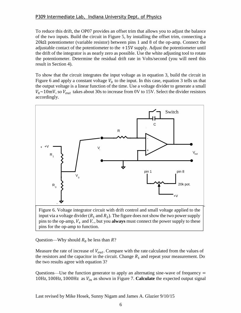
To show that the circuit integrates the input voltage as in equation 3, build the circuit in
Figure 6 and apply a constant voltage 𝑉0 to the input. In this case, equation 3 tells us that
the output voltage is a linear function of the time. Use a voltage divider to generate a small
𝑉0~10mV, so 𝑉𝑜𝑢𝑡 takes about 30s to increase from 0V to 15V. Select the divider resistors
accordingly.
Question—Why should 𝑅0 be less than 𝑅?
Measure the rate of increase of 𝑉𝑜𝑢𝑡. Compare with the rate calculated from the values of
the resistors and the capacitor in the circuit. Change 𝑅1 and repeat your measurement. Do
the two results agree with equation 3?
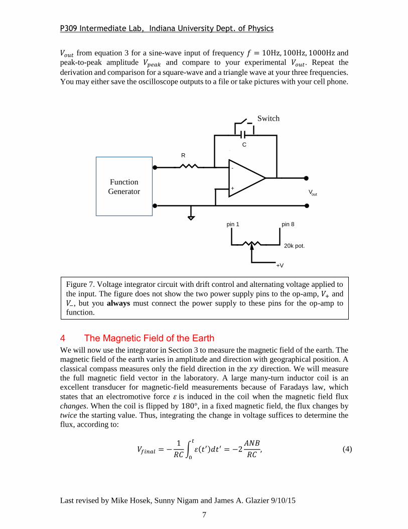
Questions—Use the function generator to apply an alternating sine-wave of frequency =10Hz, 100Hz, 1000Hz as 𝑉𝑖𝑛 as shown in Figure 7. Calculate the expected output signal
-
+
_
VV
in
out
R
C
pin 1 pin 8
20k pot.
+V
V0
+V
R
R0
1
Figure 6. Voltage integrator circuit with drift control and small voltage applied to the
input via a voltage divider (𝑅1 and 𝑅2). The figure does not show the two power supply
pins to the op-amp, 𝑉+ and 𝑉−, but you always must connect the power supply to these
pins for the op-amp to function.
Switch
-
+
_
VV
in
out
R
C
pin 1 pin 8
20k pot.
+V
V0
+V
R
R0
1
P309 Intermediate Lab, Indiana University Dept. of Physics
Last revised by Mike Hosek, Sunny Nigam and James A. Glazier 9/10/15
7
𝑉𝑜𝑢𝑡 from equation 3 for a sine-wave input of frequency 𝑓 = 10Hz, 100Hz, 1000Hz and
peak-to-peak amplitude 𝑉𝑝𝑒𝑎𝑘 and compare to your experimental 𝑉𝑜𝑢𝑡. Repeat the
derivation and comparison for a square-wave and a triangle wave at your three frequencies.
You may either save the oscilloscope outputs to a file or take pictures with your cell phone.
4 The Magnetic Field of the Earth
We will now use the integrator in Section 3 to measure the magnetic field of the earth. The
magnetic field of the earth varies in amplitude and direction with geographical position. A
classical compass measures only the field direction in the 𝑥𝑦 direction. We will measure
the full magnetic field vector in the laboratory. A large many-turn inductor coil is an
excellent transducer for magnetic-field measurements because of Faradays law, which
states that an electromotive force 휀 is induced in the coil when the magnetic field flux
changes. When the coil is flipped by 180°, in a fixed magnetic field, the flux changes by
twice the starting value. Thus, integrating the change in voltage suffices to determine the
flux, according to:
𝑉𝑓𝑖𝑛𝑎𝑙 = −1
𝑅𝐶∫ 휀(𝑡′)𝑑𝑡′
𝑡
0
= −2𝐴𝑁𝐵
𝑅𝐶, (4)
-
+
_
VV
in
out
R
C
pin 1 pin 8
20k pot.
+V
V0
+V
R
R0
1
Figure 7. Voltage integrator circuit with drift control and alternating voltage applied to
the input. The figure does not show the two power supply pins to the op-amp, 𝑉+ and
𝑉−, but you always must connect the power supply to these pins for the op-amp to
function.
Switch
Function
Generator
P309 Intermediate Lab, Indiana University Dept. of Physics
Last revised by Mike Hosek, Sunny Nigam and James A. Glazier 9/10/15
8
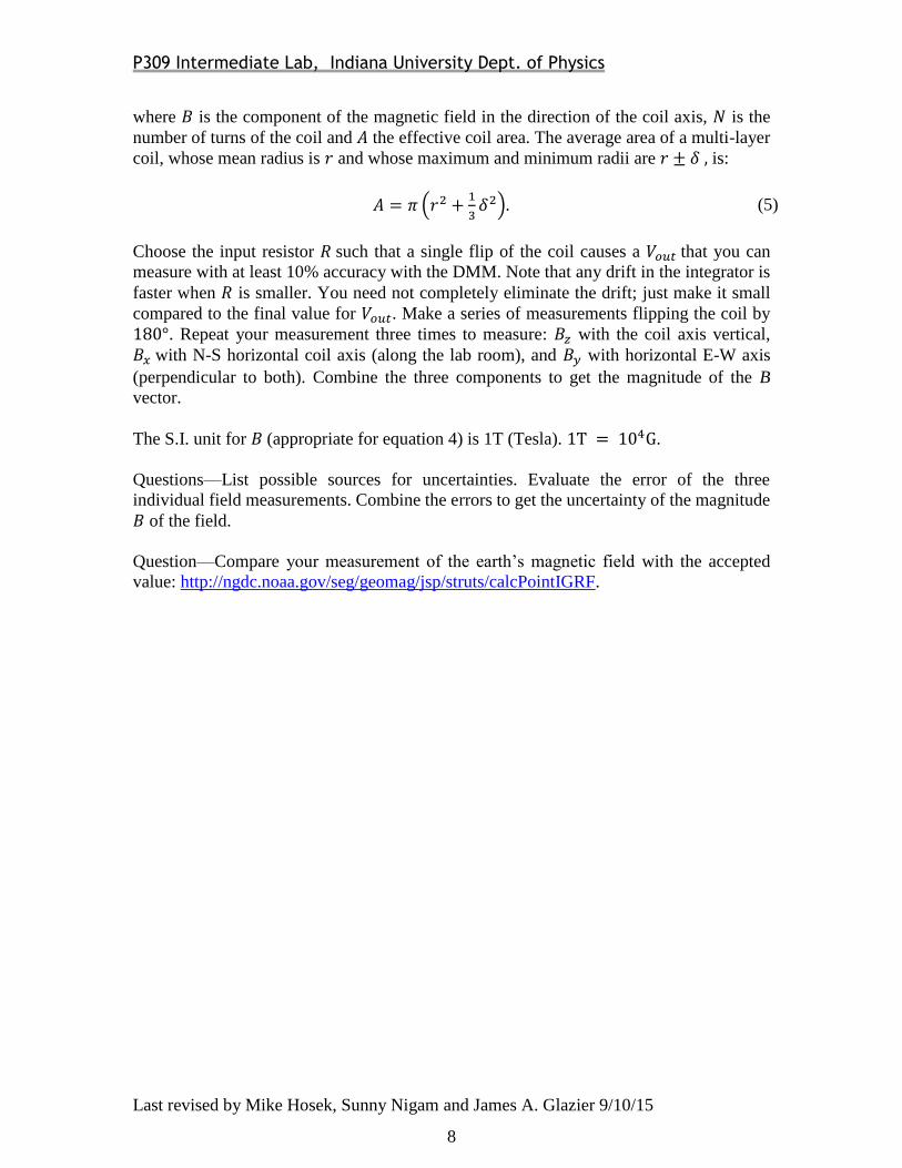
where 𝐵 is the component of the magnetic field in the direction of the coil axis, 𝑁 is the
number of turns of the coil and 𝐴 the effective coil area. The average area of a multi-layer
coil, whose mean radius is 𝑟 and whose maximum and minimum radii are 𝑟 ± 𝛿 , is:
𝐴 = 𝜋 (𝑟2 +1
3𝛿2). (5)
Choose the input resistor 𝑅 such that a single flip of the coil causes a 𝑉𝑜𝑢𝑡 that you can
measure with at least 10% accuracy with the DMM. Note that any drift in the integrator is
faster when 𝑅 is smaller. You need not completely eliminate the drift; just make it small
compared to the final value for 𝑉𝑜𝑢𝑡. Make a series of measurements flipping the coil by
180°. Repeat your measurement three times to measure: 𝐵𝑧 with the coil axis vertical,
𝐵𝑥 with N-S horizontal coil axis (along the lab room), and 𝐵𝑦 with horizontal E-W axis
(perpendicular to both). Combine the three components to get the magnitude of the B
vector.
The S.I. unit for 𝐵 (appropriate for equation 4) is 1T (Tesla). 1T = 104G.
Questions—List possible sources for uncertainties. Evaluate the error of the three
individual field measurements. Combine the errors to get the uncertainty of the magnitude
𝐵 of the field.
Question—Compare your measurement of the earth’s magnetic field with the accepted
value: http://ngdc.noaa.gov/seg/geomag/jsp/struts/calcPointIGRF.
P309 Intermediate Lab, Indiana University Dept. of Physics
Last revised by Mike Hosek, Sunny Nigam and James A. Glazier 9/10/15
9
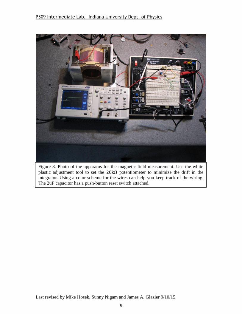
Figure 8. Photo of the apparatus for the magnetic field measurement. Use the white
plastic adjustment tool to set the 20kΩ potentiometer to minimize the drift in the
integrator. Using a color scheme for the wires can help you keep track of the wiring.
The 2uF capacitor has a push-button reset switch attached.
P309 Intermediate Lab, Indiana University Dept. of Physics
Last revised by Mike Hosek, Sunny Nigam and James A. Glazier 9/10/15
10
11
Last Revised by Mike Hosek, Sunny Nigam and James A. Glazier 9/10/15