Embed Size (px)
Citation preview
3/7/2018
Lab 3: Analog Electronics Innovation Fellows Bootcamp
Prof. Steven S. Saliterman
Exercise 3-1 Familiarization with the Lab Box Contents 3-1-1 Team Lab Box 3-1-2 Multimeter (voltage, ohm and current) and Breadboard with 1660 tie points:
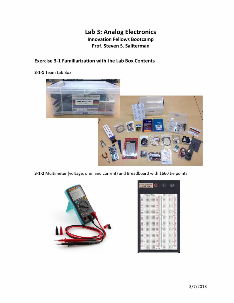
Page 2
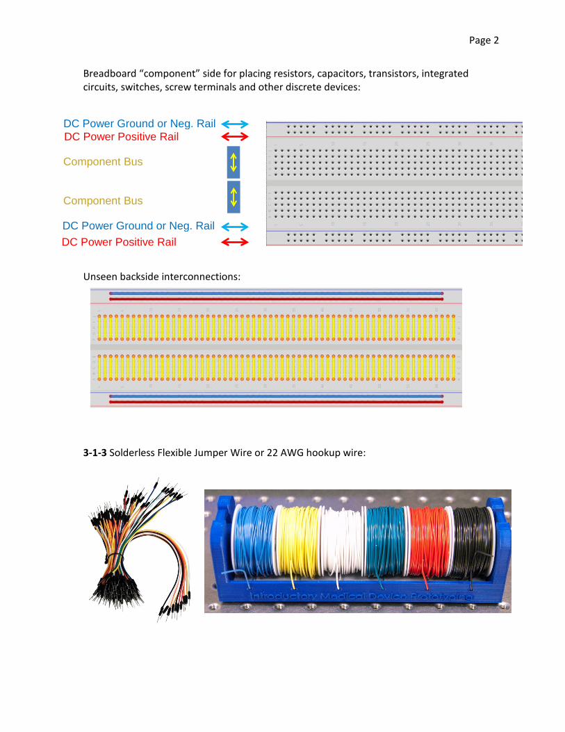
Breadboard “component” side for placing resistors, capacitors, transistors, integrated circuits, switches, screw terminals and other discrete devices: Unseen backside interconnections: 3-1-3 Solderless Flexible Jumper Wire or 22 AWG hookup wire:
DC Power Ground or Neg. Rail DC Power Positive Rail
DC Power Ground or Neg. Rail DC Power Positive Rail
Component Bus
Component Bus

Page 3
3-1-4 Wire cutter/stripper/plier and needle nose pliers: 3-1-5 Lead former: 3-1-6 Integrated circuit removal tool: Use this tool when attempting to remove an IC from a breadboard. Failure to do so could cause an IC to be imbedded in your finger!!
Page 4
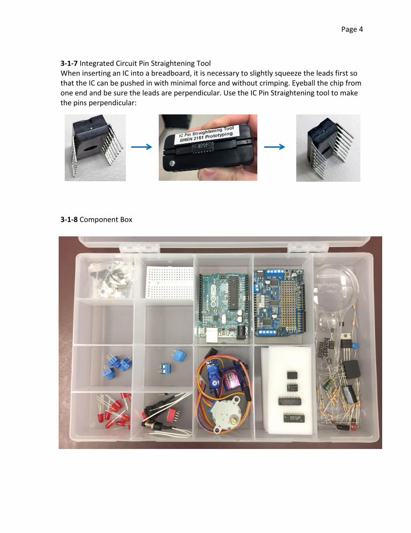
3-1-7 Integrated Circuit Pin Straightening Tool When inserting an IC into a breadboard, it is necessary to slightly squeeze the leads first so that the IC can be pushed in with minimal force and without crimping. Eyeball the chip from one end and be sure the leads are perpendicular. Use the IC Pin Straightening tool to make the pins perpendicular: 3-1-8 Component Box
Page 5
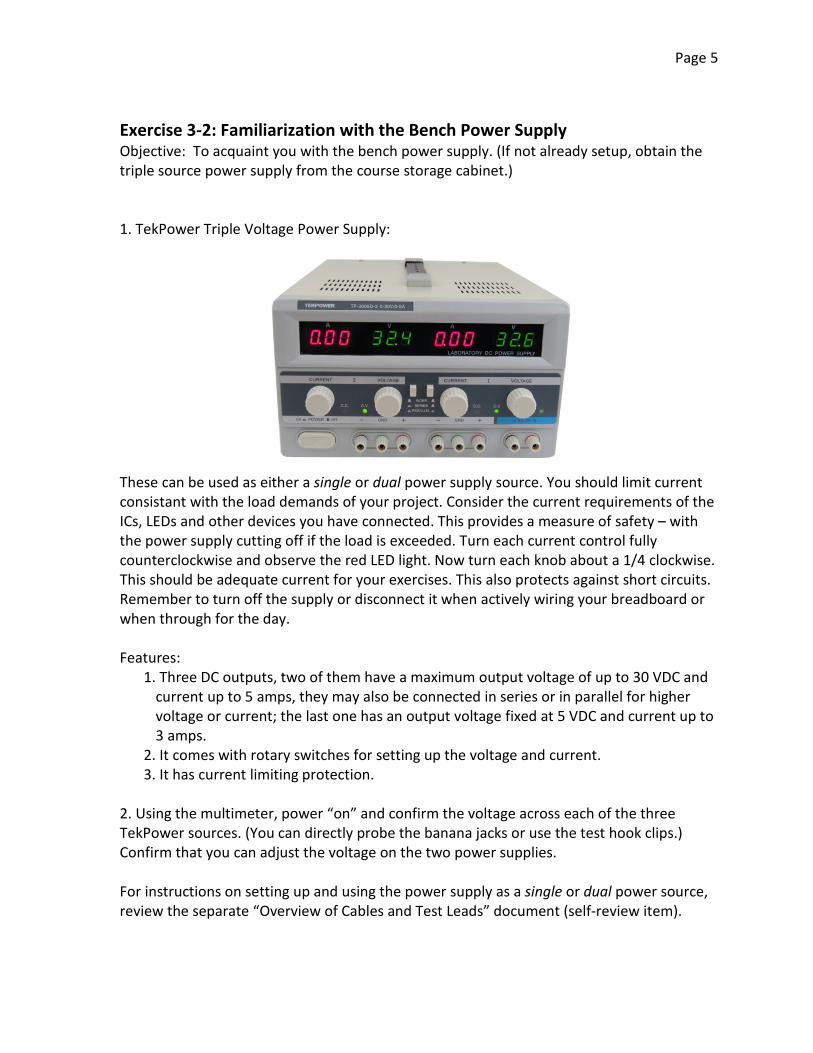
Exercise 3-2: Familiarization with the Bench Power Supply Objective: To acquaint you with the bench power supply. (If not already setup, obtain the triple source power supply from the course storage cabinet.) 1. TekPower Triple Voltage Power Supply: These can be used as either a single or dual power supply source. You should limit current consistant with the load demands of your project. Consider the current requirements of the ICs, LEDs and other devices you have connected. This provides a measure of safety – with the power supply cutting off if the load is exceeded. Turn each current control fully counterclockwise and observe the red LED light. Now turn each knob about a 1/4 clockwise. This should be adequate current for your exercises. This also protects against short circuits. Remember to turn off the supply or disconnect it when actively wiring your breadboard or when through for the day. Features:
1. Three DC outputs, two of them have a maximum output voltage of up to 30 VDC and current up to 5 amps, they may also be connected in series or in parallel for higher voltage or current; the last one has an output voltage fixed at 5 VDC and current up to 3 amps.
2. It comes with rotary switches for setting up the voltage and current. 3. It has current limiting protection.
2. Using the multimeter, power “on” and confirm the voltage across each of the three TekPower sources. (You can directly probe the banana jacks or use the test hook clips.) Confirm that you can adjust the voltage on the two power supplies. For instructions on setting up and using the power supply as a single or dual power source, review the separate “Overview of Cables and Test Leads” document (self-review item).

Page 6
Image courtesy of Hantek
Exercise 3-3: Familiarization with the Oscilloscope Objective: To understand operation and uses of an oscilloscope. (YouTube tutorial: Oscilloscopes.) 1. The Hantek 100 MHz 2 Channel Digital Oscilloscope (model DSO5102B): Features:
100 MHz bandwidth Real time sample rate Giga Samples/s Record Length up to 1M Trigger mode: edge/pulse width/line selectable video/slop/overtime etc. USB host and device connectivity, standard Multiple automatic measurements Four math functions, including FFT standard Provides software for PC real-time analysis specifications: Display: 7" TFT 16K color LCD, 800 x 480 dots.
Page 7
I t f
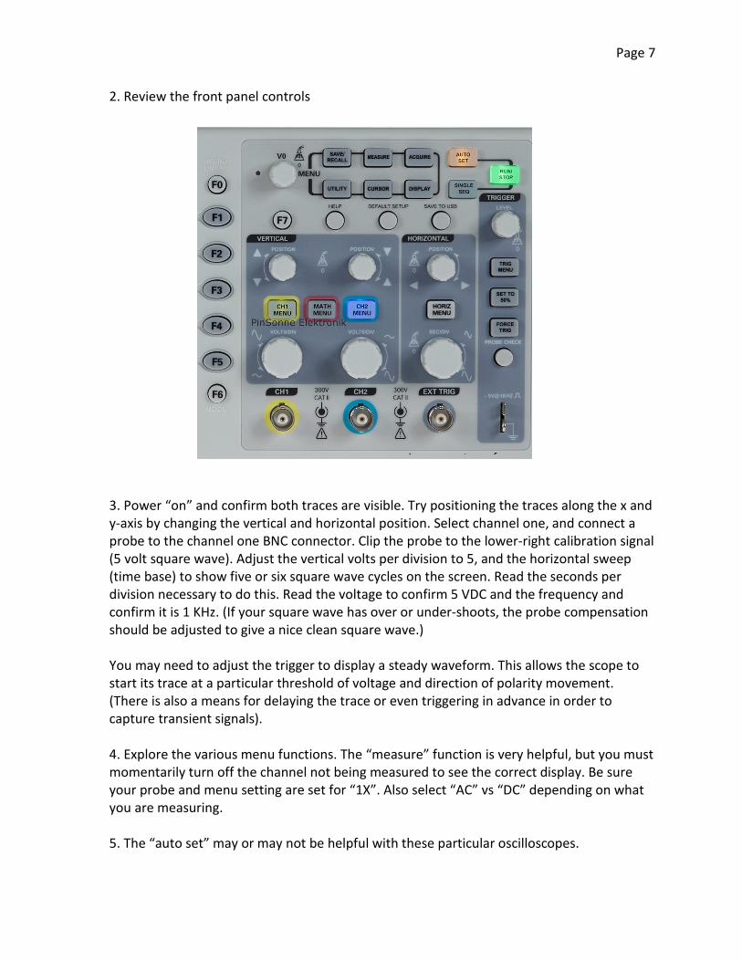
2. Review the front panel controls 3. Power “on” and confirm both traces are visible. Try positioning the traces along the x and y-axis by changing the vertical and horizontal position. Select channel one, and connect a probe to the channel one BNC connector. Clip the probe to the lower-right calibration signal (5 volt square wave). Adjust the vertical volts per division to 5, and the horizontal sweep (time base) to show five or six square wave cycles on the screen. Read the seconds per division necessary to do this. Read the voltage to confirm 5 VDC and the frequency and confirm it is 1 KHz. (If your square wave has over or under-shoots, the probe compensation should be adjusted to give a nice clean square wave.) You may need to adjust the trigger to display a steady waveform. This allows the scope to start its trace at a particular threshold of voltage and direction of polarity movement. (There is also a means for delaying the trace or even triggering in advance in order to capture transient signals). 4. Explore the various menu functions. The “measure” function is very helpful, but you must momentarily turn off the channel not being measured to see the correct display. Be sure your probe and menu setting are set for “1X”. Also select “AC” vs “DC” depending on what you are measuring. 5. The “auto set” may or may not be helpful with these particular oscilloscopes.
Page 8
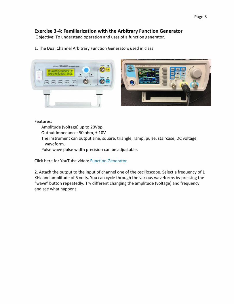
Exercise 3-4: Familiarization with the Arbitrary Function Generator Objective: To understand operation and uses of a function generator. 1. The Dual Channel Arbitrary Function Generators used in class Features:
Amplitude (voltage) up to 20Vpp Output Impedance: 50 ohm, ± 10V The instrument can output sine, square, triangle, ramp, pulse, staircase, DC voltage
waveform. Pulse wave pulse width precision can be adjustable.
Click here for YouTube video: Function Generator. 2. Attach the output to the input of channel one of the oscilloscope. Select a frequency of 1 KHz and amplitude of 5 volts. You can cycle through the various waveforms by pressing the “wave” button repeatedly. Try different changing the amplitude (voltage) and frequency and see what happens.
Page 9
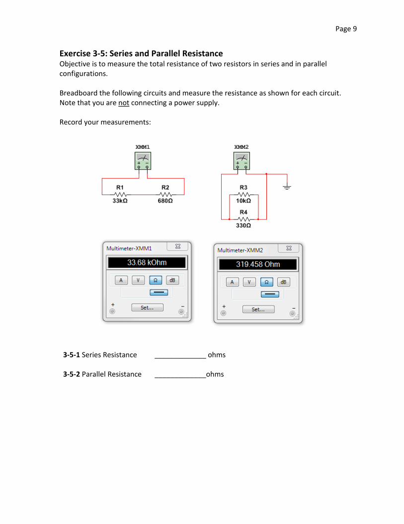
Exercise 3-5: Series and Parallel Resistance Objective is to measure the total resistance of two resistors in series and in parallel configurations. Breadboard the following circuits and measure the resistance as shown for each circuit. Note that you are not connecting a power supply. Record your measurements: 3-5-1 Series Resistance _____________ ohms 3-5-2 Parallel Resistance _____________ohms
Page 10
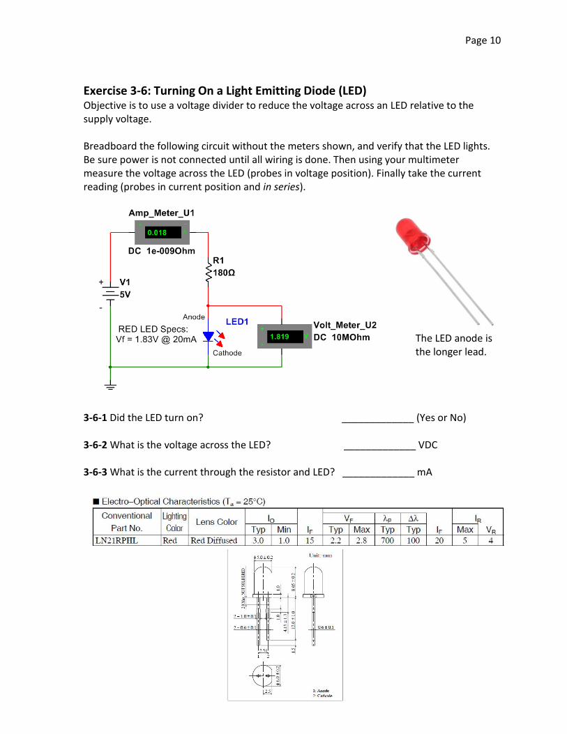
Exercise 3-6: Turning On a Light Emitting Diode (LED) Objective is to use a voltage divider to reduce the voltage across an LED relative to the supply voltage. Breadboard the following circuit without the meters shown, and verify that the LED lights. Be sure power is not connected until all wiring is done. Then using your multimeter measure the voltage across the LED (probes in voltage position). Finally take the current reading (probes in current position and in series). 3-6-1 Did the LED turn on? _____________ (Yes or No) 3-6-2 What is the voltage across the LED? _____________ VDC 3-6-3 What is the current through the resistor and LED? _____________ mA
The LED anode is the longer lead.
Page 11
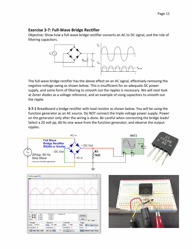
Exercise 3-7: Full-Wave Bridge Rectifier Objective: Show how a full-wave bridge rectifier converts an AC to DC signal, and the role of filtering capacitors. The full-wave bridge rectifier has the above effect on an AC signal, effectively removing the negative voltage swing as shown below. This is insufficient for an adequate DC power supply, and some form of filtering to smooth out the ripples is necessary. We will next look at Zener diodes as a voltage reference, and an example of using capacitors to smooth out the ripple. 3-7-1 Breadboard a bridge rectifier with load resistor as shown below. You will be using the function generator as an AC source. Do NOT connect the triple voltage power supply. Power on the generator only after the wiring is done. Be careful when connecting the bridge leads! Select a 20 volt pp, 60 Hz sine wave from the function generator, and observe the output ripples.
Page 12
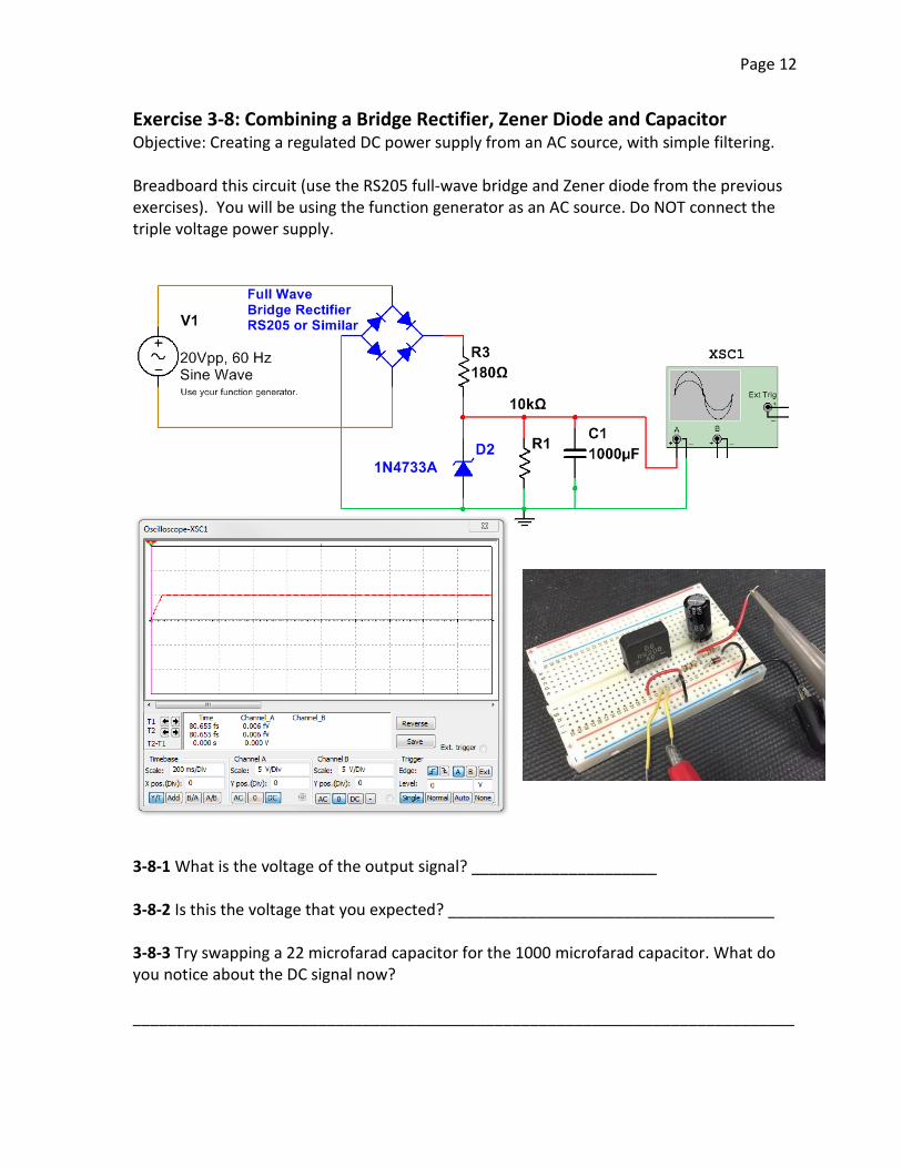
Exercise 3-8: Combining a Bridge Rectifier, Zener Diode and Capacitor Objective: Creating a regulated DC power supply from an AC source, with simple filtering. Breadboard this circuit (use the RS205 full-wave bridge and Zener diode from the previous exercises). You will be using the function generator as an AC source. Do NOT connect the triple voltage power supply. 3-8-1 What is the voltage of the output signal? _____________________ 3-8-2 Is this the voltage that you expected? _____________________________________ 3-8-3 Try swapping a 22 microfarad capacitor for the 1000 microfarad capacitor. What do you notice about the DC signal now? ___________________________________________________________________________
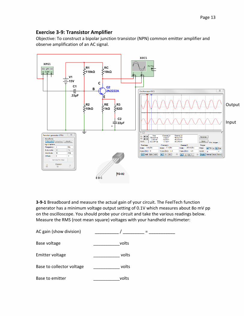
Page 13
Exercise 3-9: Transistor Amplifier Objective: To construct a bipolar junction transistor (NPN) common emitter amplifier and observe amplification of an AC signal.
3-9-1 Breadboard and measure the actual gain of your circuit. The FeelTech function generator has a minimum voltage output setting of 0.1V which measures about 8o mV pp on the oscilloscope. You should probe your circuit and take the various readings below. Measure the RMS (root mean square) voltages with your handheld multimeter: AC gain (show division) __________ / _________ = ___________ Base voltage ___________volts Emitter voltage ___________ volts Base to collector voltage ___________ volts Base to emitter ___________volts
B C
E
- Input
Output
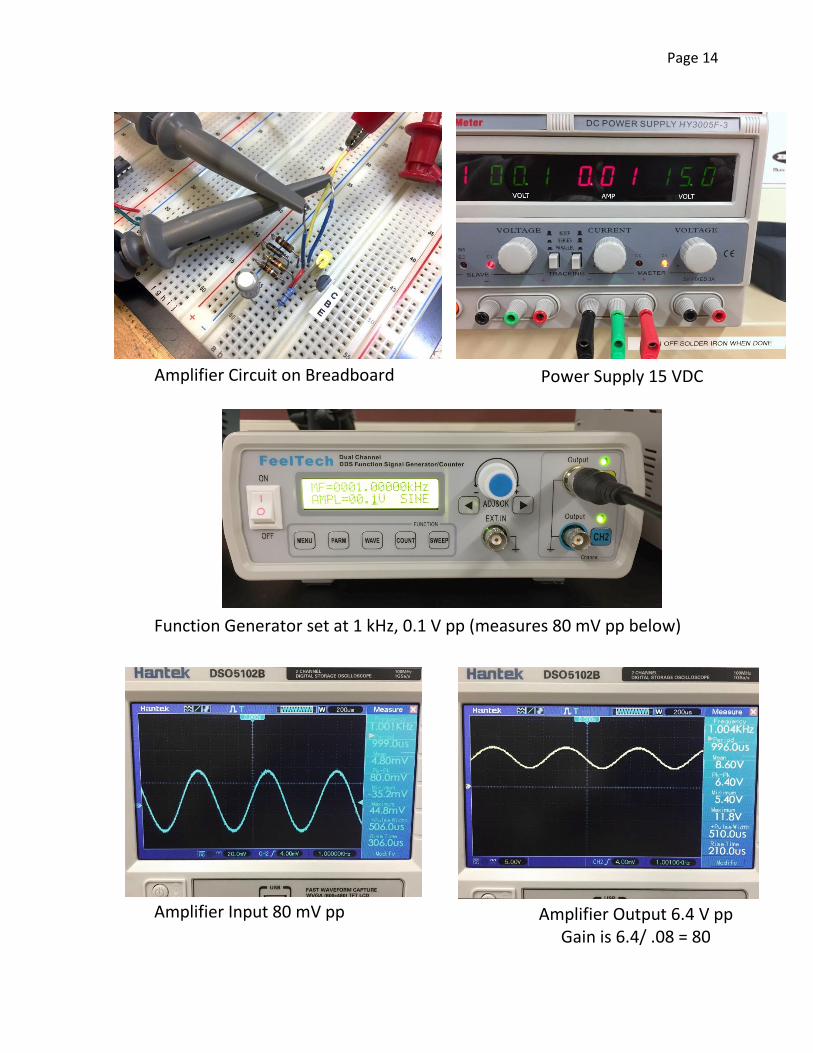
Page 14
Amplifier Circuit on Breadboard
Power Supply 15 VDC
Function Generator set at 1 kHz, 0.1 V pp (measures 80 mV pp below)
Amplifier Input 80 mV pp
Amplifier Output 6.4 V pp Gain is 6.4/ .08 = 80
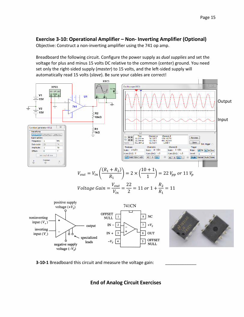
Page 15
Exercise 3-10: Operational Amplifier – Non- Inverting Amplifier (Optional) Objective: Construct a non-inverting amplifier using the 741 op amp. Breadboard the following circuit. Configure the power supply as dual supplies and set the voltage for plus and minus 15 volts DC relative to the common (center) ground. You need set only the right-sided supply (master) to 15 volts, and the left-sided supply will automatically read 15 volts (slave). Be sure your cables are correct! 3-10-1 Breadboard this circuit and measure the voltage gain: _____________
End of Analog Circuit Exercises
Input
Output
𝑉𝑉𝑜𝑜𝑜𝑜𝑜𝑜 = 𝑉𝑉𝑖𝑖𝑖𝑖 �(𝑅𝑅1 + 𝑅𝑅2)
𝑅𝑅1� = 2 × �
10 + 11
� = 22 𝑉𝑉𝑝𝑝𝑝𝑝 𝑜𝑜𝑜𝑜 11 𝑉𝑉𝑝𝑝
𝑉𝑉𝑜𝑜𝑉𝑉𝑉𝑉𝑉𝑉𝑉𝑉𝑉𝑉 𝐺𝐺𝑉𝑉𝐺𝐺𝐺𝐺 =𝑉𝑉𝑜𝑜𝑜𝑜𝑜𝑜𝑉𝑉𝑖𝑖𝑖𝑖
=222
= 11 𝑜𝑜𝑜𝑜 1 +𝑅𝑅2𝑅𝑅1
= 11