Embed Size (px)
DESCRIPTION
Lab 1: GPIO. GPIO on MSP430. 6 ports on MS430F1611 Port 1 Port 2 Port 3 Port 4 Port 5 Port 6 Each port has 8 pins Px.0 ~ Px.7. Multiplexed. Port pins are often multiplexed Means it may have more than one function Example: P1.0/TACLK It can be P1.0 GPIO Or it can be TACLK - PowerPoint PPT Presentation
Citation preview
Network and Systems Laboratorynslab.ee.ntu.edu.tw
Network and Systems Laboratorynslab.ee.ntu.edu.tw
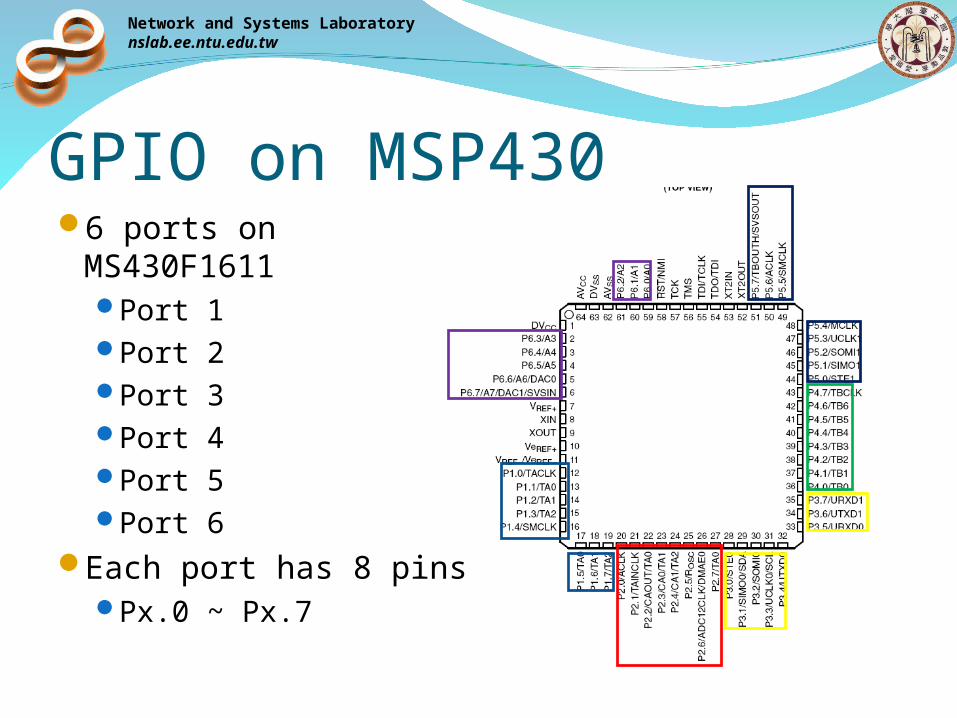
GPIO on MSP4306 ports on
MS430F1611Port 1Port 2Port 3Port 4Port 5Port 6
Each port has 8 pinsPx.0 ~ Px.7

Network and Systems Laboratorynslab.ee.ntu.edu.tw
MultiplexedPort pins are often
multiplexedMeans it may have
more than one functionExample: P1.0/TACLK
It can be P1.0 GPIOOr it can be TACLK
You must select the function you want
Network and Systems Laboratorynslab.ee.ntu.edu.tw
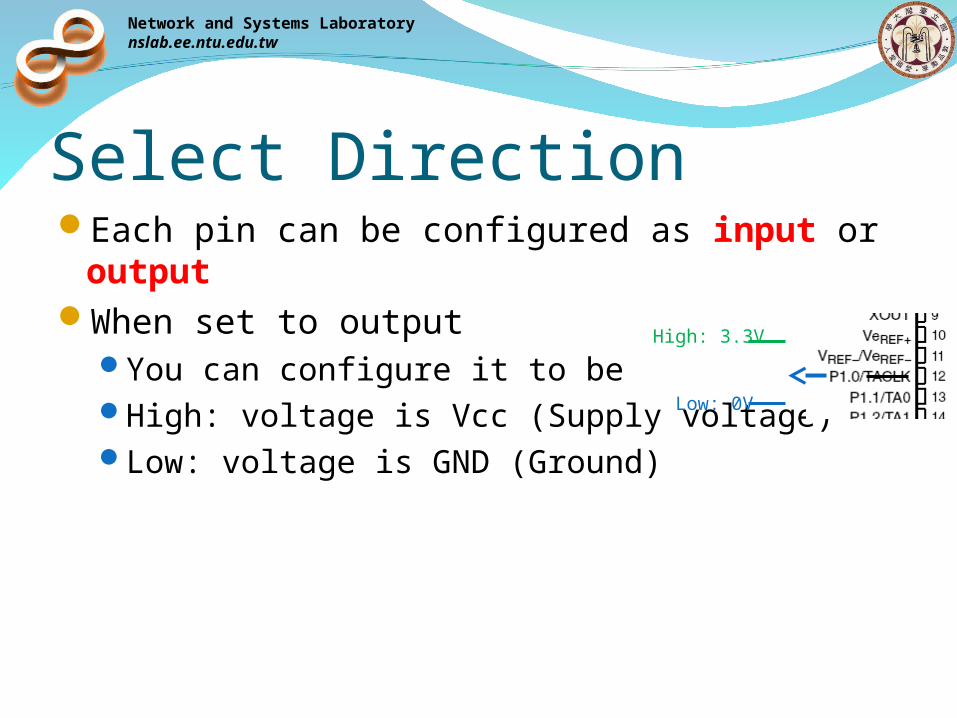
Each pin can be configured as input or output
When set to outputYou can configure it to beHigh: voltage is Vcc (Supply voltage)Low: voltage is GND (Ground)
High: 3.3V
Select Direction
Low: 0V
Network and Systems Laboratorynslab.ee.ntu.edu.tw
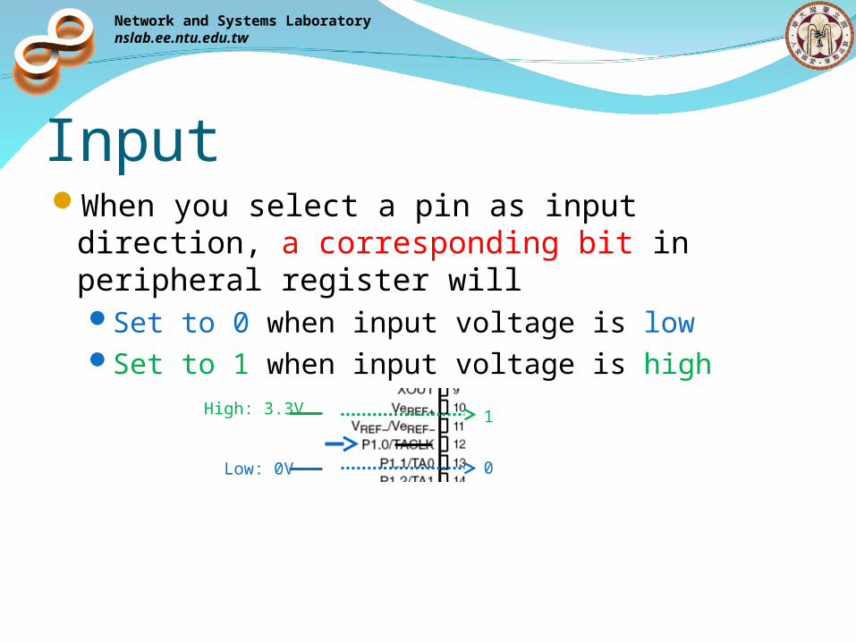
InputWhen you select a pin as input direction, a
corresponding bit in peripheral register willSet to 0 when input voltage is lowSet to 1 when input voltage is high
High: 3.3V
Low: 0V
1
0
Network and Systems Laboratorynslab.ee.ntu.edu.tw
InterruptsOnly P1 and P2 are interruptibleFor each pin in P1 and P2, you can enable or
disable its interruptEnable means it will detects interruptDisable means nothing happen when interrupt
occur
Network and Systems Laboratorynslab.ee.ntu.edu.tw
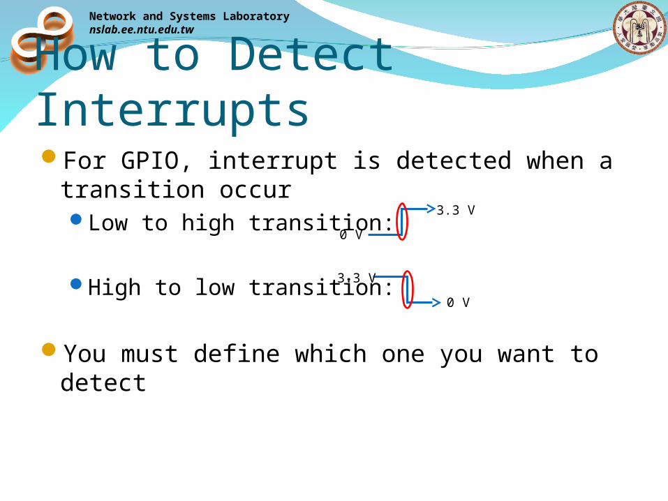
How to Detect InterruptsFor GPIO, interrupt is detected when a
transition occurLow to high transition:
High to low transition:
You must define which one you want to detect
0 V
3.3 V
0 V
3.3 V
Network and Systems Laboratorynslab.ee.ntu.edu.tw
Interrupt FlagWhen the MCU detects an interrupt
A corresponding bit in peripheral register will set to 1
Branch to ISRYou must clear the GPIO interrupt flag in
softwareMeans you must set the bit to 0or the program will re-enter the ISR again
Network and Systems Laboratorynslab.ee.ntu.edu.tw
GPIO RegistersEach GPIO port has four registers
Input: PxINOutput: PxOUTDirection: PxDIRPort Select(function select): PxSEL
P1 and P2 have three moreInterrupt flag: PxIFGInterrupt edge select: PxIESInterrupt enable: PxIE
Each register is 8-bit longx represent the port number
Network and Systems Laboratorynslab.ee.ntu.edu.tw
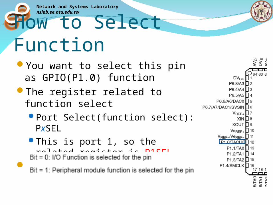
How to Select FunctionYou want to select this pin as
GPIO(P1.0) functionThe register related to function
selectPort Select(function select): PxSELThis is port 1, so the related
register is P1SELFrom user guide
Network and Systems Laboratorynslab.ee.ntu.edu.tw
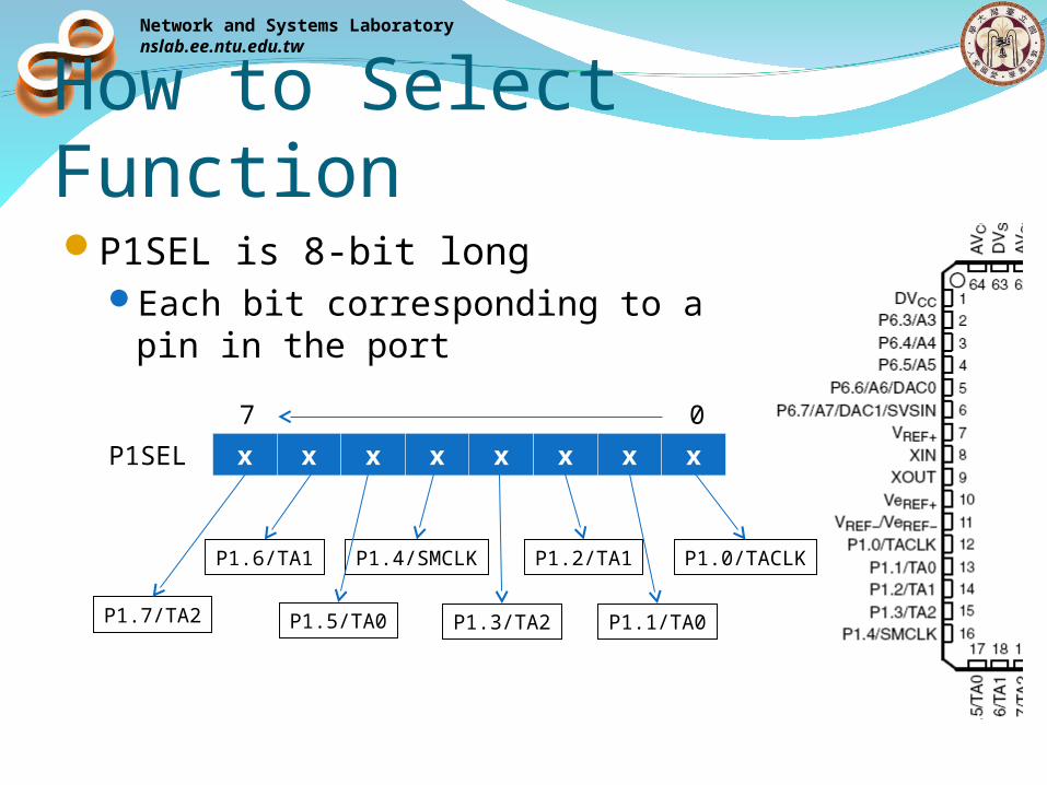
How to Select FunctionP1SEL is 8-bit long
Each bit corresponding to a pin in the port
P1SEL x x x x x x x x
07
P1.0/TACLK
P1.1/TA0
P1.2/TA1
P1.3/TA2
P1.4/SMCLK
P1.5/TA0
P1.6/TA1
P1.7/TA2
Network and Systems Laboratorynslab.ee.ntu.edu.tw
How to Select Function
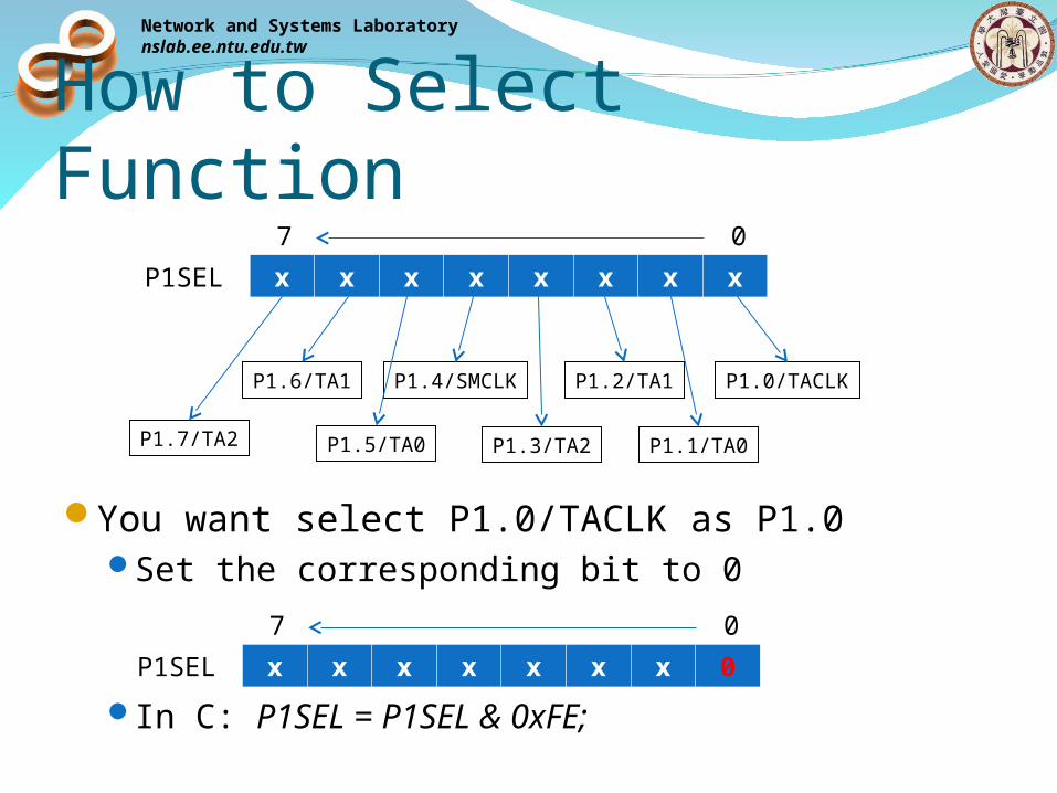
You want select P1.0/TACLK as P1.0Set the corresponding bit to 0
In C: P1SEL = P1SEL & 0xFE;
P1SEL x x x x x x x x
07
P1.0/TACLK
P1.1/TA0
P1.2/TA1
P1.3/TA2
P1.4/SMCLK
P1.5/TA0
P1.6/TA1
P1.7/TA2
P1SEL x x x x x x x 0
07
Network and Systems Laboratorynslab.ee.ntu.edu.tw
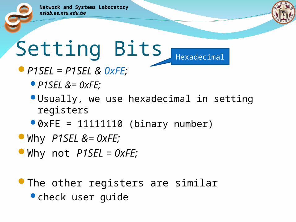
Setting BitsP1SEL = P1SEL & 0xFE;
P1SEL &= 0xFE;Usually, we use hexadecimal in setting
registers0xFE = 11111110 (binary number)
Why P1SEL &= 0xFE; Why not P1SEL = 0xFE;
The other registers are similarcheck user guide
Hexadecimal
Network and Systems Laboratorynslab.ee.ntu.edu.tw
GPIO Interrupt All P1 pins source a single interrupt vector,
and all P2 pins source a different single interrupt vector.Interrupts generated by P1.0, P1.1, …, P1.7 all
go to same ISRHow do you know which one generate the
interruptcheck interrupt flag

Network and Systems Laboratorynslab.ee.ntu.edu.tw
Hardware LEDsSwitchesKeypad
Network and Systems Laboratorynslab.ee.ntu.edu.tw
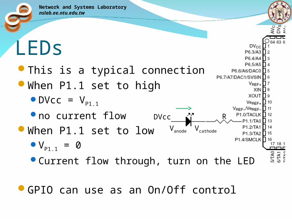
LEDsThis is a typical connectionWhen P1.1 set to high
DVcc = VP1.1
no current flowWhen P1.1 set to low
VP1.1 = 0Current flow through, turn on the LED
GPIO can use as an On/Off control
DVcc
Vanode Vcathode
R
Network and Systems Laboratorynslab.ee.ntu.edu.tw
Control LEDsLook at Taroko schematic
which pins the LEDs connected toThese pins should be input direction or output
direction?How to set these pins to high (or low)
Network and Systems Laboratorynslab.ee.ntu.edu.tw
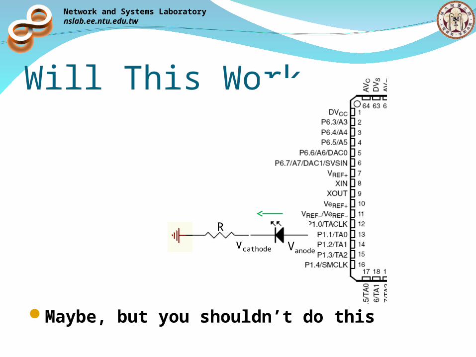
Will This Work
Maybe, but you shouldn’t do this
VanodeVcathode
R
Network and Systems Laboratorynslab.ee.ntu.edu.tw
Max Current Source/SinkEach pin has a maximum amount of current it
can provide(source) or accept(sink)For MSP430
Max source: 6mA Max sink: 6mA
Usually it can sink more current than it can source
You cannot use those pin as a power source (or sink) for any sensor/circuit directly
Network and Systems Laboratorynslab.ee.ntu.edu.tw
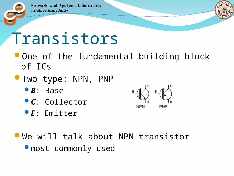
TransistorsOne of the fundamental building block of ICsTwo type: NPN, PNP
B: BaseC: CollectorE: Emitter
We will talk about NPN transistormost commonly used
Network and Systems Laboratorynslab.ee.ntu.edu.tw
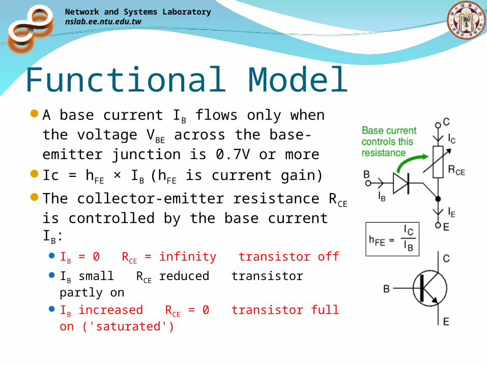
Functional ModelA base current IB flows only when the
voltage VBE across the base-emitter junction is 0.7V or more
Ic = hFE × IB (hFE is current gain)
The collector-emitter resistance RCE is controlled by the base current IB: IB = 0 RCE = infinity transistor off
IB small RCE reduced transistor partly on
IB increased RCE = 0 transistor full on ('saturated')
Network and Systems Laboratorynslab.ee.ntu.edu.tw
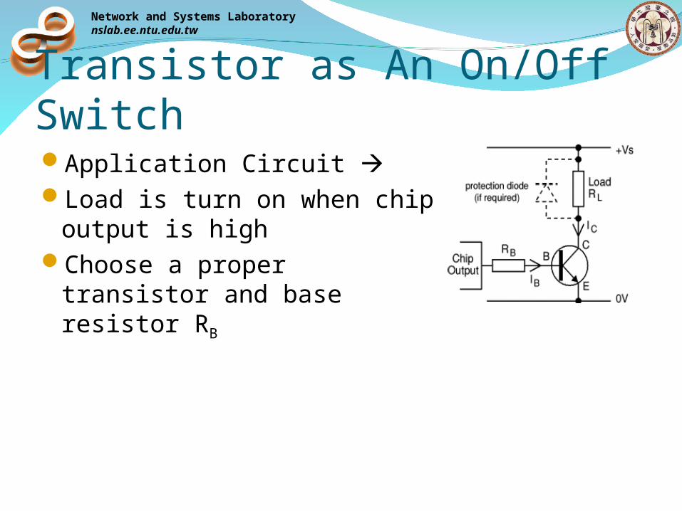
Transistor as An On/Off SwitchApplication Circuit Load is turn on when chip
output is highChoose a proper transistor
and base resistor RB
Network and Systems Laboratorynslab.ee.ntu.edu.tw
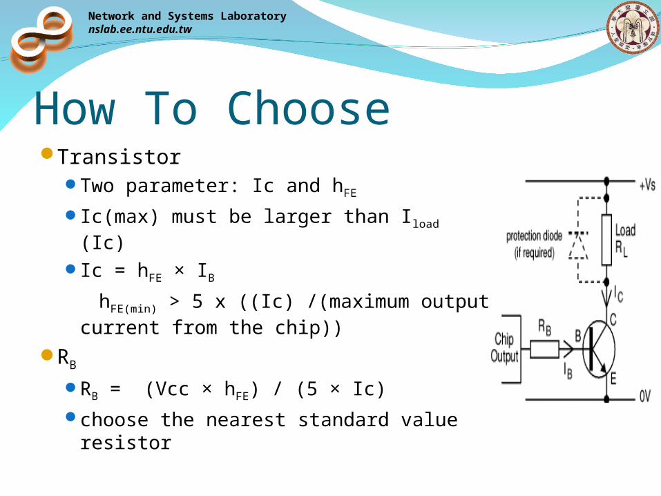
How To ChooseTransistor
Two parameter: Ic and hFE
Ic(max) must be larger than Iload (Ic)
Ic = hFE × IB hFE(min) > 5 x ((Ic) /(maximum output
current from the chip))RB
RB = (Vcc × hFE) / (5 × Ic)choose the nearest standard value
resistor
Network and Systems Laboratorynslab.ee.ntu.edu.tw
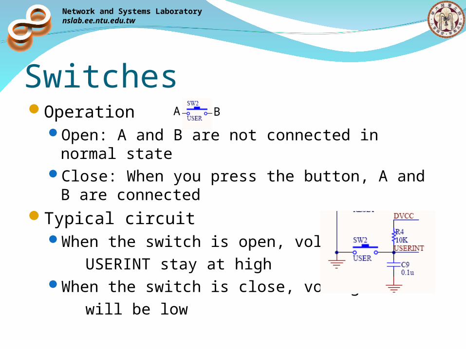
SwitchesOperation
Open: A and B are not connected in normal state
Close: When you press the button, A and B are connected
Typical circuitWhen the switch is open, voltage of USERINT stay at highWhen the switch is close, voltage of will be low
A B
Network and Systems Laboratorynslab.ee.ntu.edu.tw
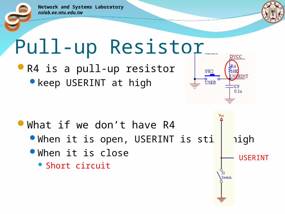
Pull-up ResistorR4 is a pull-up resistor
keep USERINT at high
What if we don’t have R4When it is open, USERINT is still highWhen it is close
Short circuitUSERINT
Network and Systems Laboratorynslab.ee.ntu.edu.tw
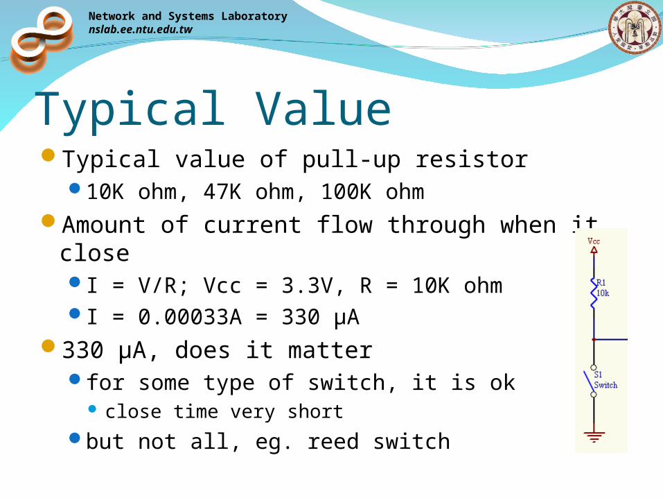
Typical ValueTypical value of pull-up resistor
10K ohm, 47K ohm, 100K ohmAmount of current flow through when it close
I = V/R; Vcc = 3.3V, R = 10K ohmI = 0.00033A = 330 μA
330 μA, does it matterfor some type of switch, it is ok
close time very shortbut not all, eg. reed switch

Network and Systems Laboratorynslab.ee.ntu.edu.tw
Value of Pull-upTo save power, can we use very large pull-up
resistor?ans: No
Network and Systems Laboratorynslab.ee.ntu.edu.tw
ImpedanceResistance: R = V/I
relation ship between the magnitude of the voltage and current
Impedance: Z = V/I (there are complex number)relation ship between the magnitude and phase
of the voltage and current
Network and Systems Laboratorynslab.ee.ntu.edu.tw
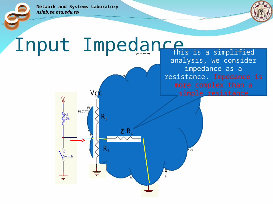
Input Impedance
Z Ri
R1
Ri
Vcc
This is a simplified analysis, we consider impedance as a
resistance. Impedance is more complex than a simple
resistance
Network and Systems Laboratorynslab.ee.ntu.edu.tw
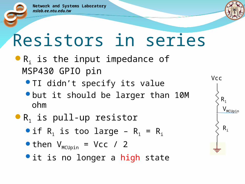
Resistors in seriesRi is the input impedance of MSP430
GPIO pinTI didn’t specify its valuebut it should be larger than 10M ohm
R1 is pull-up resistorif R1 is too large – R1 = Ri
then VMCUpin = Vcc / 2it is no longer a high state
R1
Ri
Vcc
VMCUpin
Network and Systems Laboratorynslab.ee.ntu.edu.tw
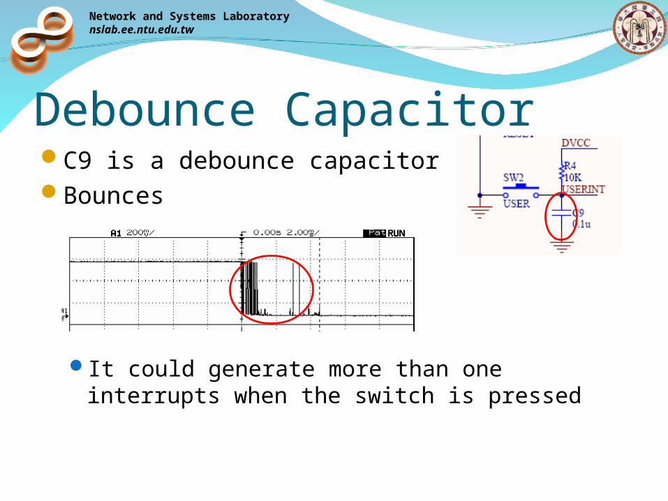
Debounce CapacitorC9 is a debounce capacitorBounces
It could generate more than one interrupts when the switch is pressed
Network and Systems Laboratorynslab.ee.ntu.edu.tw
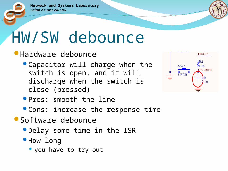
HW/SW debounceHardware debounce
Capacitor will charge when the switch is open, and it will discharge when the switch is close (pressed)
Pros: smooth the lineCons: increase the response time
Software debounceDelay some time in the ISRHow long
you have to try out
Network and Systems Laboratorynslab.ee.ntu.edu.tw
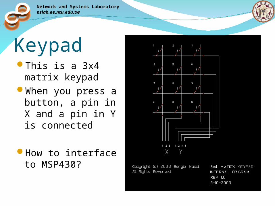
KeypadThis is a 3x4
matrix keypadWhen you press a
button, a pin in X and a pin in Y is connected
How to interface to MSP430?
Network and Systems Laboratorynslab.ee.ntu.edu.tw
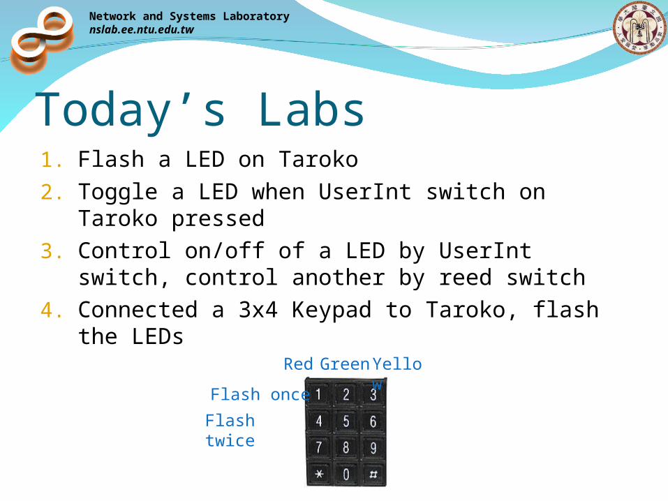
Today’s Labs1. Flash a LED on Taroko2. Toggle a LED when UserInt switch on Taroko
pressed3. Control on/off of a LED by UserInt switch, control
another by reed switch4. Connected a 3x4 Keypad to Taroko, flash the
LEDsRed GreenYellow
Flash once
Flash twice
Network and Systems Laboratorynslab.ee.ntu.edu.tw
JTAG DriverC:\Program Files\IAR Systems\Embedded
Workbench Evaluation 4.0\430\drivers\TIUSBFET\WinXP
Network and Systems Laboratorynslab.ee.ntu.edu.tw
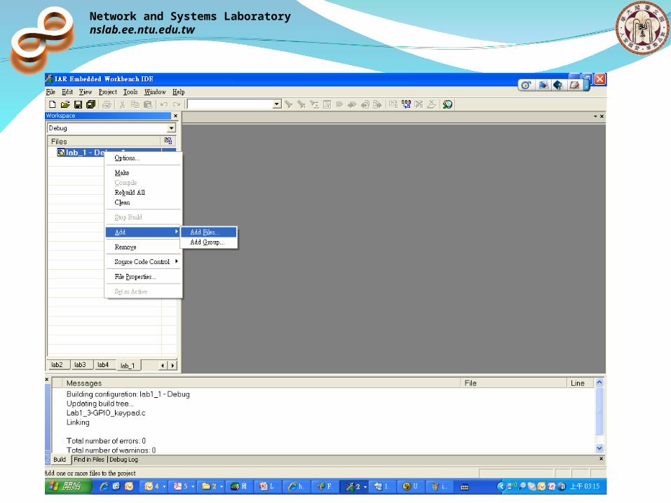
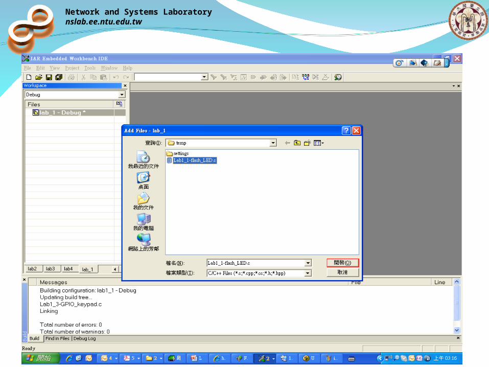
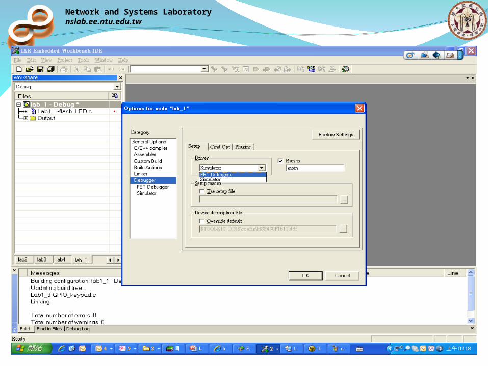
IAR Setting
Network and Systems Laboratorynslab.ee.ntu.edu.tw
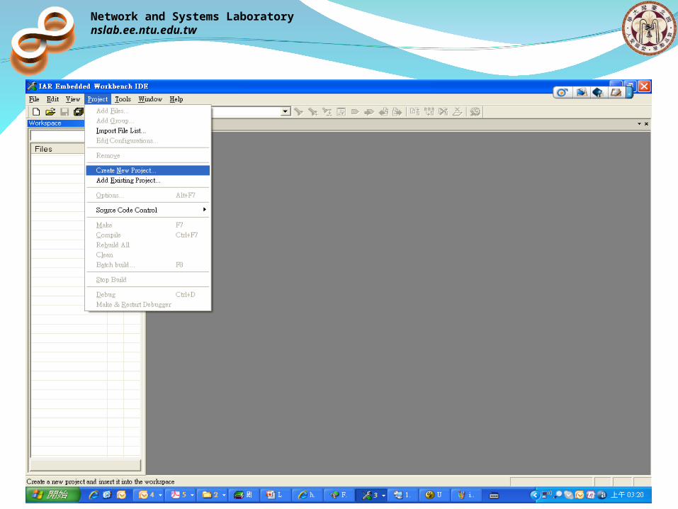
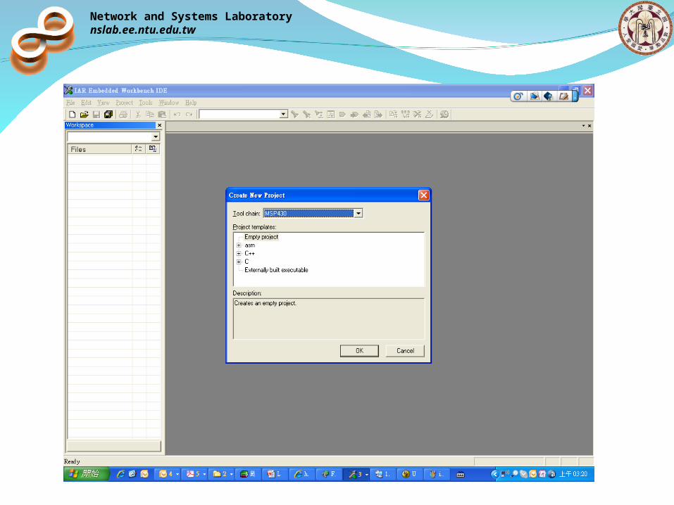
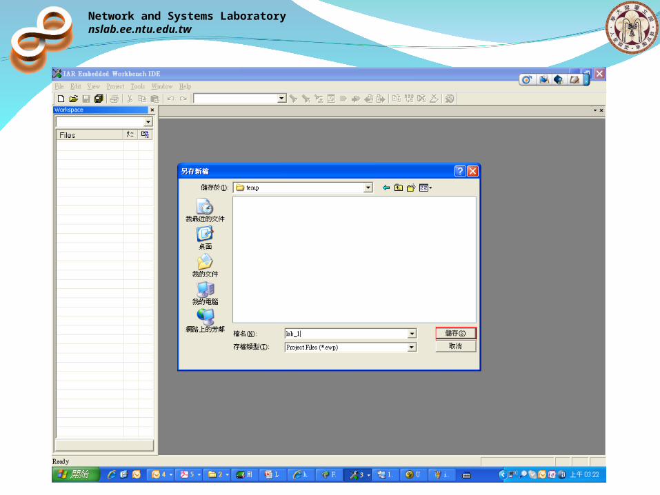
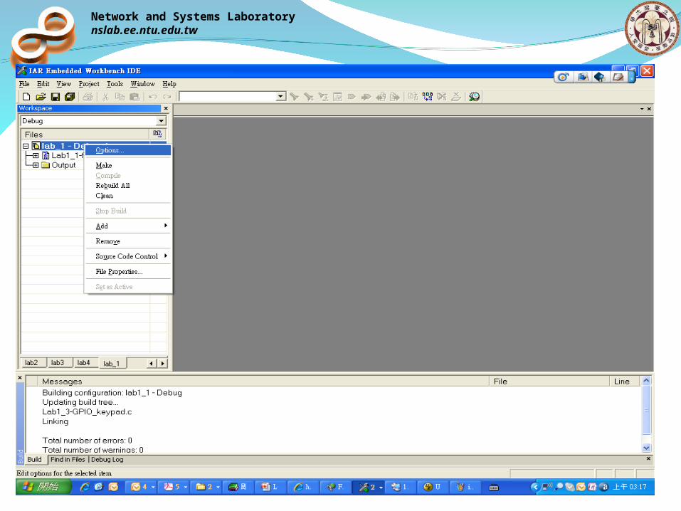
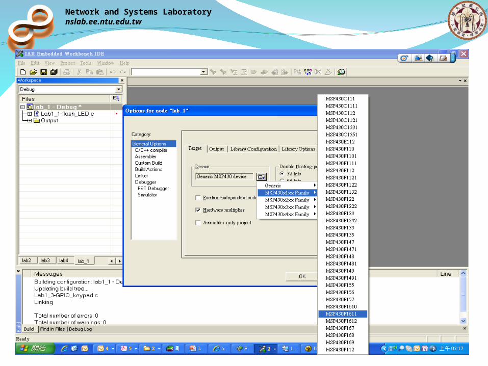
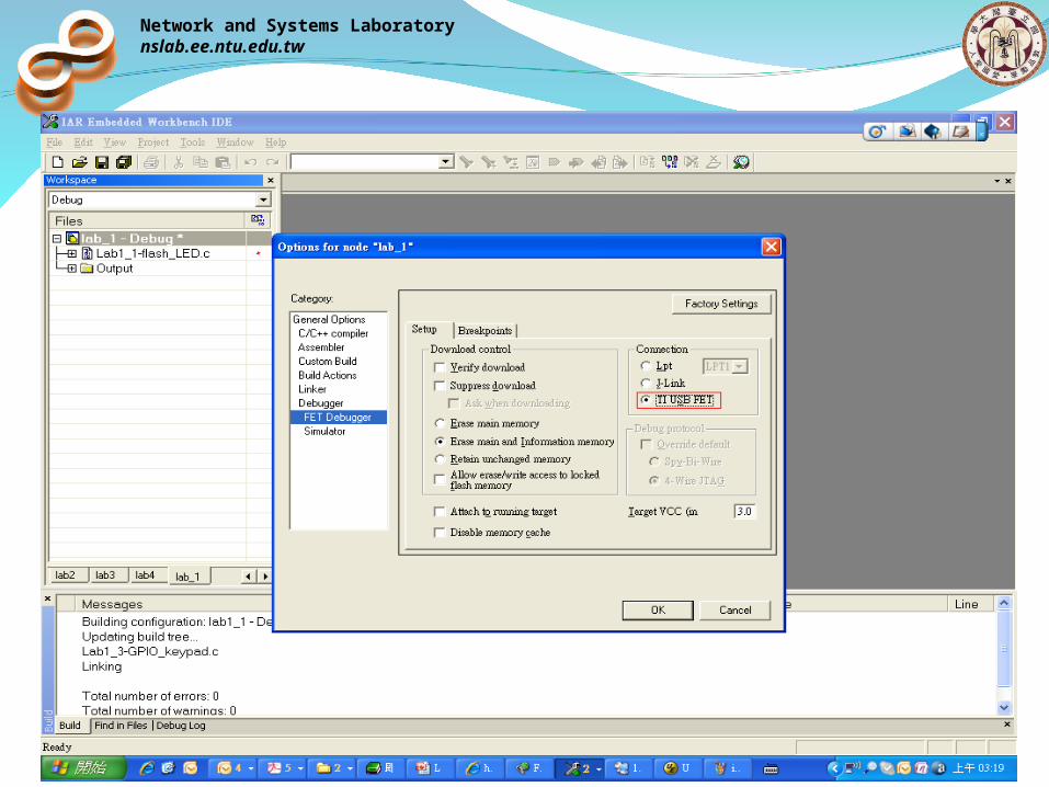
IAR Setting
Network and Systems Laboratorynslab.ee.ntu.edu.tw
Network and Systems Laboratorynslab.ee.ntu.edu.tw
Network and Systems Laboratorynslab.ee.ntu.edu.tw
Network and Systems Laboratorynslab.ee.ntu.edu.tw
Network and Systems Laboratorynslab.ee.ntu.edu.tw
Network and Systems Laboratorynslab.ee.ntu.edu.tw
Network and Systems Laboratorynslab.ee.ntu.edu.tw
Network and Systems Laboratorynslab.ee.ntu.edu.tw


![107 1 GPIO .ppt [相容模式]](https://img.pdfslide.us/doc/110x75/61dd2610d4cc4456f1428964/107-1-gpio-ppt-.jpg)