Embed Size (px)
Citation preview

Sonoma State University Department of Engineering Science Fall 2017
1
EE 110 Introduction to Engineering & Laboratory Experience
Saeid Rahimi, Ph.D. Lab 1
DC Concepts and Measurement: Ohm's Law, Voltage ad Current Introduction to Analog Discovery Scope
Last week we introduced the traditional laboratory equipment including DC and AC power supplies and oscilloscopes. The goal was for students to understand the basic operation of each instrument without going into details. This lab includes two parts. In part 1 we will introduce the traditional laboratory equipment (power supply, function generator, oscilloscope, and multimeter) and use the power supply and multimeter to introduce the concepts of voltage, current and resistance. In part 2 we will use the Analog Discovery Scope (DS) instrument (instead of the laboratory instruments) to perform the same basic measurements. The functions of the DS which integrates all the traditional laboratory instruments into a small box will be described. Analog Discovery Scopes (DS) were purchased by the department so students could borrow and use them outside of the laboratory. The hardware is small enough to be placed in the students backpacks.
Part 1: DC Concepts and Measurement
DC Power Supplies A power supply is a device that provides the energy required to power up a circuit. In this section we will experiment with DC (Direct Current) power supplies. Of course, we can use the Discovery Scope (DS) as a source of power while realizing that the DS itself is powered by your laptop computer. We will experiment with the AC (Alternating Current) power supplies or function generators in the future labs. Batteries are the most common types of DC power supplies. Multimeters are commonly used for measurement of basic electrical resistance, voltage, and current. Today you will use your own multimeter for measurement of voltage and current.
Ohm's Law - A review Ohm's law states that the voltage drop across a resistor has a linear relationship to the current flowing through the resistor.
V = R I
Graphically this linear relationship (similar to the familiar y = m x) is represented by a line when the current through the resistor is plotted against the voltage across it. This graph is termed I-V characteristic of the device. A linear I-V graph indicates that the resistance of the device remains constant over a wide range of currents and voltages. For many electronic devices the resistance is not a constant and varies with the applied voltage and current. These devices possess non-linear I-V characteristics. However, the
Sonoma State University Department of Engineering Science Fall 2017
2
slope of the curve at any given point determines the resistance of the device for that particular current and voltage.
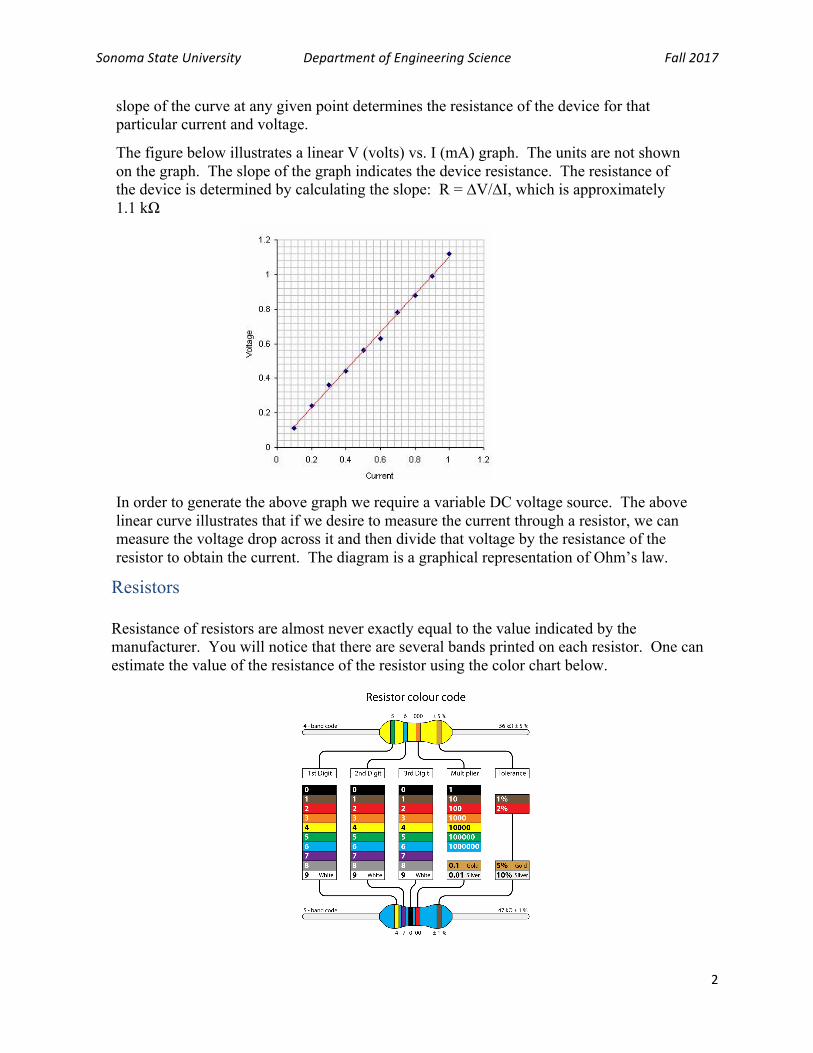
The figure below illustrates a linear V (volts) vs. I (mA) graph. The units are not shown on the graph. The slope of the graph indicates the device resistance. The resistance of the device is determined by calculating the slope: R = ∆V/∆I, which is approximately 1.1 kΩ
In order to generate the above graph we require a variable DC voltage source. The above linear curve illustrates that if we desire to measure the current through a resistor, we can measure the voltage drop across it and then divide that voltage by the resistance of the resistor to obtain the current. The diagram is a graphical representation of Ohm’s law.
Resistors Resistance of resistors are almost never exactly equal to the value indicated by the manufacturer. You will notice that there are several bands printed on each resistor. One can estimate the value of the resistance of the resistor using the color chart below.

Sonoma State University Department of Engineering Science Fall 2017
3
In the absence of a multimeter, these charts provide a convenient way to estimate the resistance of a resistor. However, you should use your multimeters to measure the exact resistance of the resistors that you intend to use in the circuit.
Electric Current Electric current, which is a measure of motion of electric charges across a point in the circuit, is the result of application of electric potential difference (voltage V) to the ends of a resistor R. The relationship among V, R and I is described by the Ohm’s law (V = R I). V is expressed in volts (V), R in Ohms (Ω) and I in Amps (A). For smaller or larger quantities of voltage, resistance and current, we multiply or divide the units by 1000: Pico (p): 10-12, Nano (n): 10-9, Micro (µ): 10-6, Milli (m): 10-3, Kilo (k): 103, Mega (M): 106, Giga (G): 109, Tera (T): 1012, etc. Example: Apply 5 V voltage across a 200 Ω resistor and calculate the current. Ohm’s Law: V = R I ! I = V/R ! I = 5 V/200 Ω ! I = 0.025 A ! I = 25 mA
How to Measure Electric Voltage, Resistance and Current?
In this lab we will use multimeters to measure V, R and I. A multimeter typically has two probes. It is important to note that you can measure the voltage across a circuit element while the circuit is active. Simply touch the two ends of the element with the multimeter probes.
However, in order to measure resistance of an element, it should be taken out of the circuit first.
To measure current, you will need to insert the multimeter in series with the element in the circuit.
It is simpler to use Ohm’s law to calculate the current in a circuit (I = V/R) rather than measuring it (see the example given above).

Sonoma State University Department of Engineering Science Fall 2017
4
Experiment 1 Assemble the following circuit on your breadboard
At the bottom of the circuit you see the symbol for a DC power supply (or battery). In this part we will use the laboratory DC power supply for V1.
We will use the same circuit and the DS power supply in the next part of the lab. The symbols for resistors and Ground are also shown in the diagram. You should be able to use a computer simulation software (Multisim or similar) to draw the above circuit. Note that the high voltage side of the battery is shown with a + sign and the low voltage side of the circuit is indicated by the ground. Create the following table in your lab book and use your multimeter to measure the following quantities. Remember to include units for all quantities.
R1 R2 V1 VAB VBC VAC IR1 IR2
Part 2: Introduction to Discovery Scope (DS)
The goal of this part of the lab is to become familiar with the Discovery Scope (DS) as a tool that functions as a DC power supply and multimeter. You will first need to download the DS software to your laptop computers. Your instructor will demonstrate the process of downloading the software from the Discovery Scope web site. For this part of the experiment you will need to connect the DS to your laptop through the USB port. Next, you will need to become familiar with the pin diagram of the DS. In the first glance, the number of DS wires could be
R1
300Ω
R2
1kΩ
V1
5V
B CA
XMM1
The DS is used as the source of voltage (battery)
Your multimeter (voltmeter)
+
Ground
"High" side of the circuit "Low" side of the circuit

Sonoma State University Department of Engineering Science Fall 2017
5
overwhelming. However, they are conveniently color coded and you can identify each wire by referring to the ping diagram.
Experiment 2 Download the pin diagram of the DS by googling “Analog Discovery Scope”. Copy and paste the pin diagram in a document and later paste a hard copy of the diagram in your lab book. The pins are color coded. Two pairs of pins are use as the input of the oscilloscope. Two pins provide positive and negative 5 volts of DC voltage, and four pins are connected to the system’s ground. Two pins deliver AC waveforms and two pins are used for triggering purposes (not used in this lab). The remaining 16 pins are used for digital Input/output purposes. Each student is assigned a DS box that in addition to the DS unit includes a set of colored wires with female end pins that are used to connect to the DS pins. Included in the box you will find a USB cable that connects the DS to a laptop. In addition to providing a screen for viewing the results and uploading and downloading codes, the laptop is also used to power up the DS. Open the boxes and explore various parts of the DS and its pins. The pin diagram is described by the instructor. Prior to receiving the “numbered” DS boxes, students fill out forms and pledge to return the devices to the department at the end of the semester. For future reference paste a copy of the pin diagram in your lab book.
Download DS Software The download takes a few minutes. Once installed, students are ready to do part 2 of this lab.

Sonoma State University Department of Engineering Science Fall 2017
6
DC Measurement In this section of the lab we will use the laboratory power supply as a variable source of voltage and the DS as a meter to test the output of the power supply. First connect the DS to your laptop and launch the DS application. Next, identify the output terminals of the power supply and the input pins of the DS (referred to as the I/O, or input/output pins). The DS has several I/O pins. Choose one of the sixteen I/O pins as your input port and connect the “high” output of the power supply to that pin. To create a return path for the current, connect the ground or “low” of the power supply to one of the ground pins of the DS (colored black). Choose the following voltages for the output of the poser supply and check and confirm the values with your DS: 1 V, 2 V, 3 V, 4 V. Record the output readings of the power supply and the input readings of the DS in a table.
DS as a DC Power Supply and a Function Generator In this section students use the DS as the source of DC and AC voltages. This part is the reverse of part 3. Use multimeters and the traditional laboratory instruments to measure the DC and AC output of the DS. The instructor describes the current, voltage, and frequency limitations of the DS compared to the standard laboratory instruments. n this part of the experiment you will use your breadboard to power a simple circuit with the power supply feature of the DS. Connect a 300 Ohm resistor to a 1 k Ohm resistor in series as shown in the diagram below. In order to pass a current through these resistors we will use the DS as a source of power (battery). Note that the power output of the DS is limited and if you need large current and power output you will need to use a more powerful power supply. The DC output of the DS is limited to +/- 5 V and the current output of the DS through its I/O ports is limited to few tens of mA.
Apply 5 V to the circuit and use your multimeter to measure the voltages across each resistor. Record your measurements in a table in your lab books. Confirm that the sum of the voltages across the two resistors is equal to 5 volts.
R1 R2 V1 VAB VBC VAC IR1 IR2
R1
300Ω
R2
1kΩ
V1
5V
B CA
XMM1
The DS is used as the source of voltage (battery)
Your multimeter (voltmeter)
+
Ground
"High" side of the circuit "Low" side of the circuit