Embed Size (px)
Citation preview
CSE369, Spring 2021L7: Building Blocks II
Intro to Digital DesignCircuit Building Blocks IIInstructor: Clarice Larson
“Every decade is the decade that tests the limits of Moore’s Law, and this decade is no different … To that end, today IBM is announcing it has created the world’s first 2 nanometer node chip.”“Today’s announcement states that IBM’s 2nm development will improve performance by 45% at the same power, or 75% energy at the same performance, compared to modern 7nm processors.“IBM states that the technology can fit 50 billion transistors onto a chip the size of a fingernail’.”https://www.anandtech.com/show/16656/ibm-creates-first-2nm-chip
IBM Creates First 2nm Chip
CSE369, Spring 2021L7: Building Blocks II
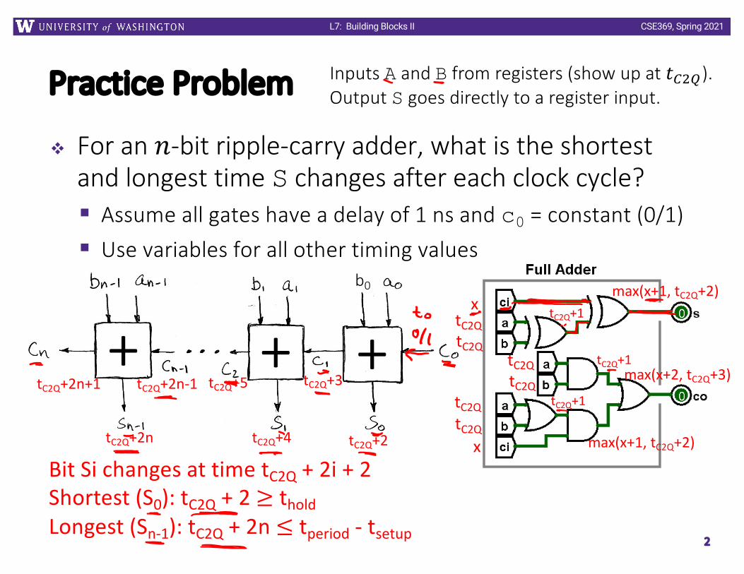
Practice Problem
v For an 𝑛-bit ripple-carry adder, what is the shortest and longest time S changes after each clock cycle? § Assume all gates have a delay of 1 ns and c0 = constant (0/1)§ Use variables for all other timing values
2
Inputs A and B from registers (show up at 𝑡!"#).Output S goes directly to a register input.
+ + +b0
x
x
tC2QtC2Q
tC2QtC2Q
tC2QtC2Q
tC2Q+1
tC2Q+1
tC2Q+1
max(x+1, tC2Q+2)
max(x+2, tC2Q+3)
max(x+1, tC2Q+2)
tC2Q+2
tC2Q+3
tC2Q+4
tC2Q+5tC2Q+2n-1tC2Q+2n+1
tC2Q+2n
Bit Si changes at time tC2Q + 2i + 2Shortest (S0): tC2Q + 2 ≥ tholdLongest (Sn-1): tC2Q + 2n ≤ tperiod - tsetup

CSE369, Spring 2021L7: Building Blocks II
Administrivia
v Mid-Quarter Course Evaluation Feedbackv Lab 6 – Useful Components
§ Modifying Lab 5 game to implement common circuit elements
§ Build a tunable computer opponent!
v Quiz 2 is next week in lecture§ First 25 minutes, worth 10% of your course grade§ On Lectures 4-5: Sequential Logic, Timing, FSMs, and Verilog§ Past Quiz 2 (+ solutions) on website: Files → Quizzes
3

CSE369, Spring 2021L7: Building Blocks II
Outline
v Routing Elementsv Registers and Counters
4
CSE369, Spring 2021L7: Building Blocks II
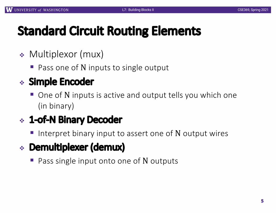
Standard Circuit Routing Elements
v Multiplexor (mux)§ Pass one of N inputs to single output
v Simple Encoder§ One of N inputs is active and output tells you which one
(in binary)
v 1-of-N Binary Decoder§ Interpret binary input to assert one of N output wires
v Demultiplexer (demux)§ Pass single input onto one of N outputs
5

CSE369, Spring 2021L7: Building Blocks II
Design Example: Basic Telephone System
v Put together a simple closed telephone system§ Multiple subscribers, single operator§ Operator controls all connections
6
SMBG
Go/Start
Bell/Alert
A/D Microphone
D/A Speaker
CSE369, Spring 2021L7: Building Blocks II
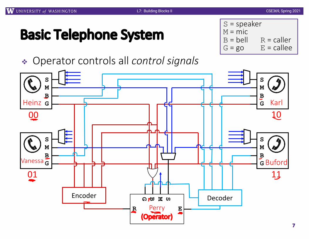
Basic Telephone System
v Operator controls all control signals
7
SMBG
SMBG
SMBG
SMBG
SMBG
Heinz
Vanessa
Karl
Buford
Perry(Operator)
S = speakerM = micB = bell R = callerG = go E = callee
ER
Encoder
c
c
c
cc
c
00
01
10
11
Decoder
c
c
c
cc
c
c
c
c
c
c
c
c
c
c
c
c
c c c
c ccc
c
c
CSE369, Spring 2021L7: Building Blocks II
Encoder
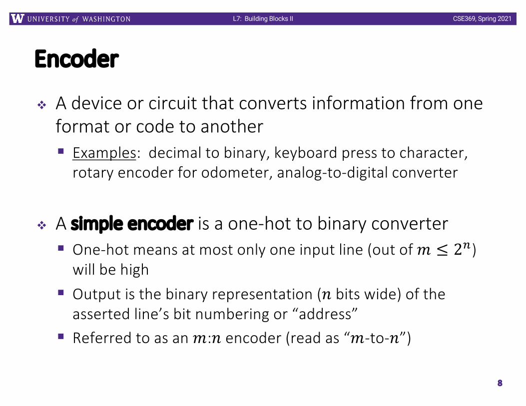
v A device or circuit that converts information from one format or code to another§ Examples: decimal to binary, keyboard press to character,
rotary encoder for odometer, analog-to-digital converter
v A simple encoder is a one-hot to binary converter§ One-hot means at most only one input line (out of 𝑚 ≤ 2!)
will be high§ Output is the binary representation (𝑛 bits wide) of the
asserted line’s bit numbering or “address”§ Referred to as an 𝑚:𝑛 encoder (read as “𝑚-to-𝑛”)
8

CSE369, Spring 2021L7: Building Blocks II
Simple Encoder Implementation
v 4:2 Encoder
v Two issues:1) What if multiple inputs are hot?2) What if no inputs are hot?
9
D3 D2 D1 D0 A1 A0
0 0 0 1
0 0 1 0
0 1 0 0
1 0 0 0
Encoder A1A0
D3D2D1D0
CSE369, Spring 2021L7: Building Blocks II
Priority Encoder
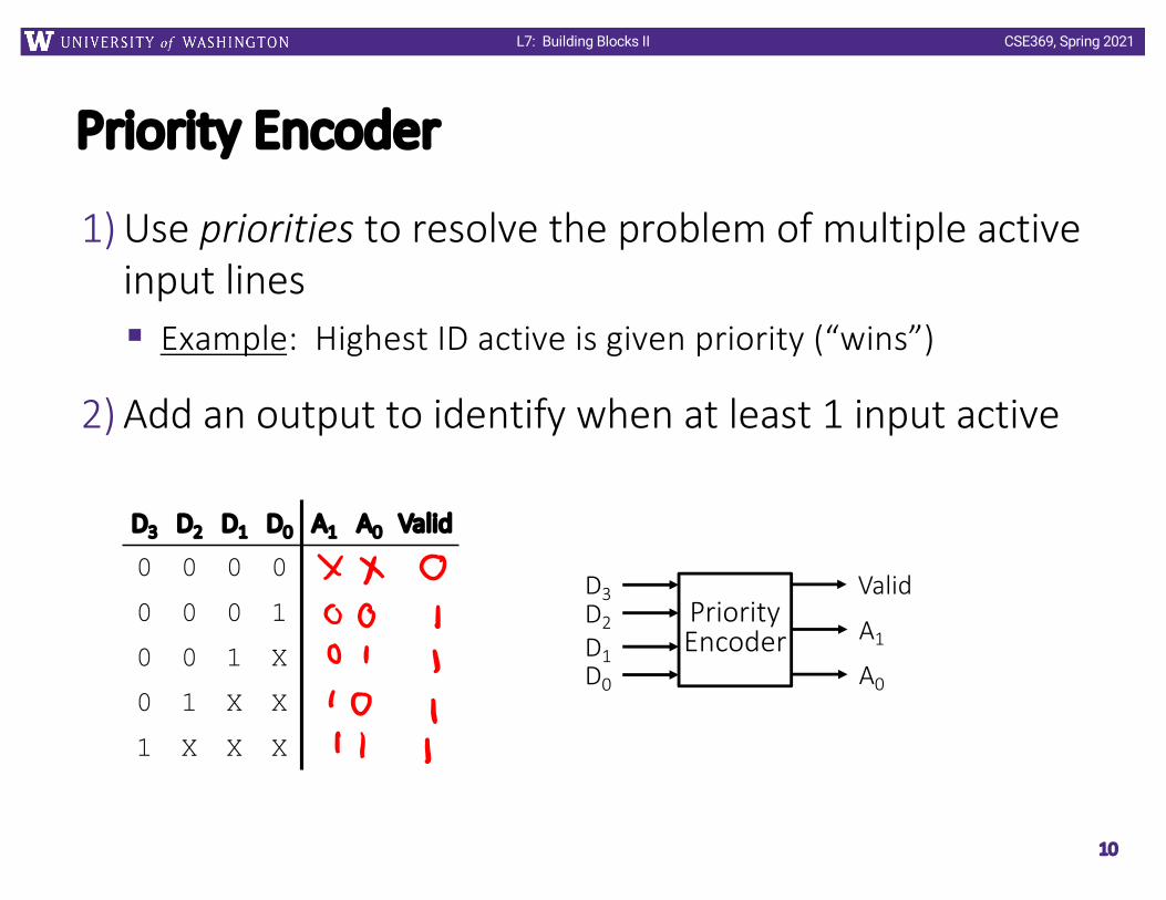
1) Use priorities to resolve the problem of multiple active input lines§ Example: Highest ID active is given priority (“wins”)
2) Add an output to identify when at least 1 input active
10
D3 D2 D1 D0 A1 A0 Valid
0 0 0 0
0 0 0 1
0 0 1 X
0 1 X X
1 X X X
PriorityEncoder A1
A0
D3D2D1D0
Valid
CSE369, Spring 2021L7: Building Blocks II
Encoder Examples
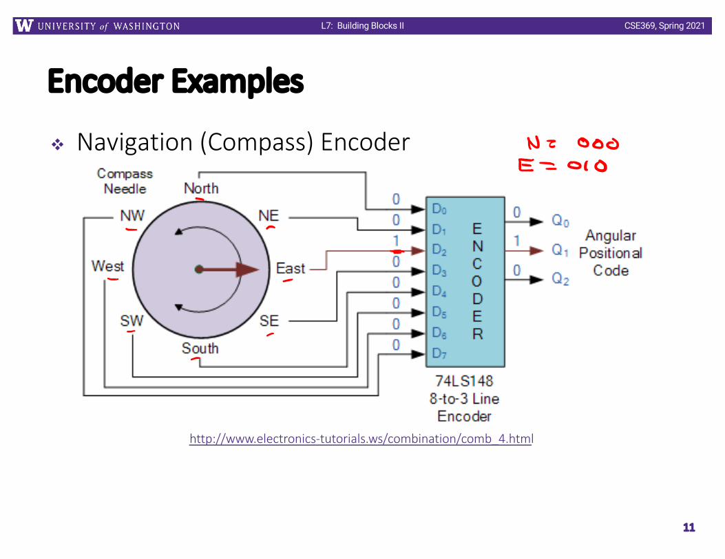
v Navigation (Compass) Encoder
11
http://www.electronics-tutorials.ws/combination/comb_4.html

CSE369, Spring 2021L7: Building Blocks II
12
Encoder Examples
v Analog-to-Digital Converter (ADC)
https://www.electronics-tutorials.ws/combination/analogue-to-digital-converter.html

CSE369, Spring 2021L7: Building Blocks II
Decoder
v A device or circuit that converts or interprets information from an encoded format§ Examples: binary to decimal, CPU instruction decoder, video
decoder (analog to digital)
v A binary decoder is a binary to one-hot converter§ 𝑛 input bits serve as bit number or “address” specifier§ Only corresponding output out of 𝑚 ≤ 2! will be asserted§ Referred to as an 𝑛:𝑚 decoder (read as “𝑛-to-𝑚”)
13
CSE369, Spring 2021L7: Building Blocks II
1-of-N Binary Decoder Implementation
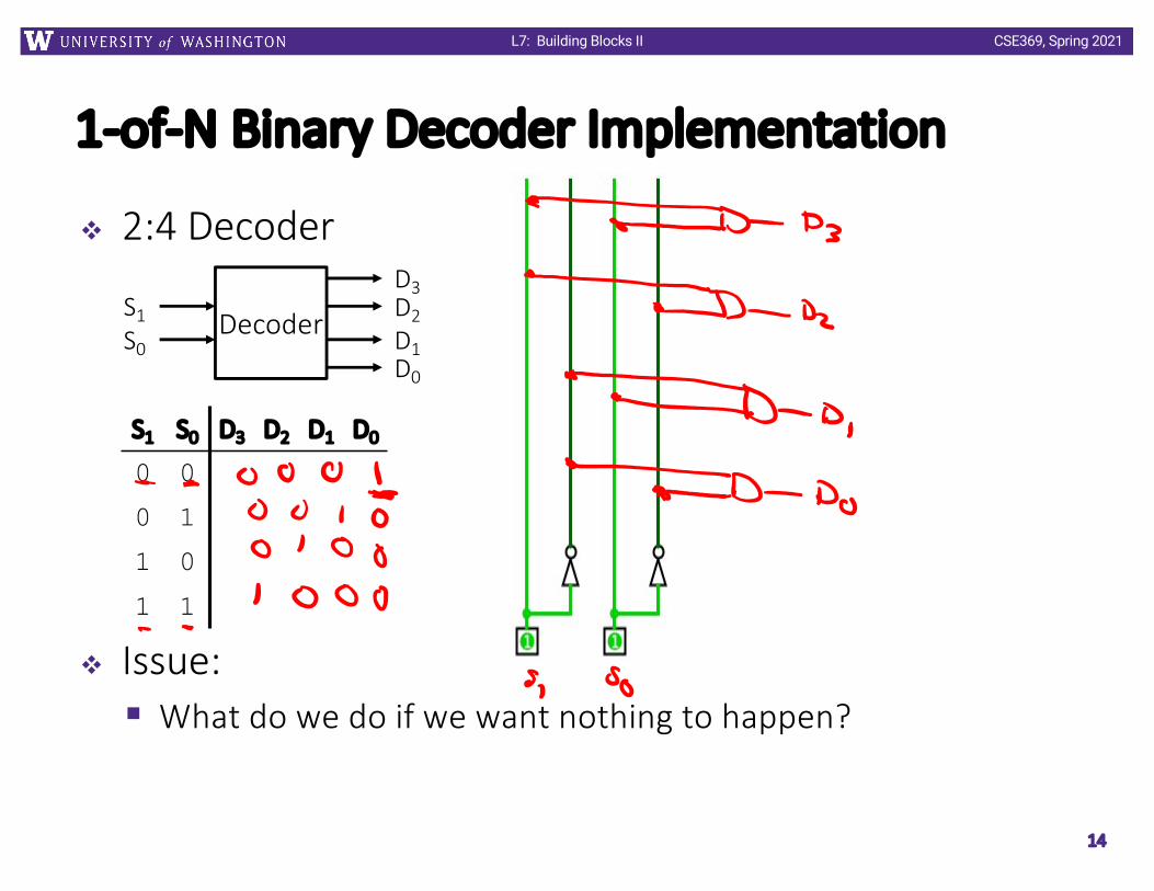
v 2:4 Decoder
v Issue:§ What do we do if we want nothing to happen?
14
S1 S0 D3 D2 D1 D0
0 0
0 1
1 0
1 1
DecoderS1S0
D3D2D1D0

CSE369, Spring 2021L7: Building Blocks II
Enabled Decoder
v Only have active output when Enable signal is high
15
EnabledDecoderS1
S0
D3D2D1D0
Enable
Enable S1 S0 D3 D2 D1 D0
0 X X
1 0 0
1 0 1
1 1 0
1 1 1
CSE369, Spring 2021L7: Building Blocks II
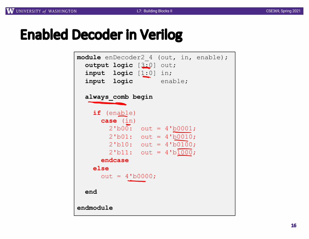
Enabled Decoder in Verilog
16
module enDecoder2_4 (out, in, enable);output logic [3:0] out;input logic [1:0] in;input logic enable;
always_comb begin
if (enable)case (in)
2'b00: out = 4'b0001;2'b01: out = 4'b0010;2'b10: out = 4'b0100;2'b11: out = 4'b1000;
endcaseelse
out = 4'b0000;
end
endmodule

CSE369, Spring 2021L7: Building Blocks II
Decoder Examples: Demultiplexer
v 1-bit 1-to-2 DEMUX:
v Truth Table:
§ More generally, AND d$ output from decoder with every input bit that is wired to DEMUX output D%
17
S I D1 D00 0 0 00 1 0 11 0 0 01 1 1 0
1
11
1
I
S
D1
D00
1

CSE369, Spring 2021L7: Building Blocks II
Decoder Examples
v Binary to 7-seg display§ You’ve already made this in this class!
18
http://www.learnabout-electronics.org/Digital/dig44.php
CSE369, Spring 2021L7: Building Blocks II
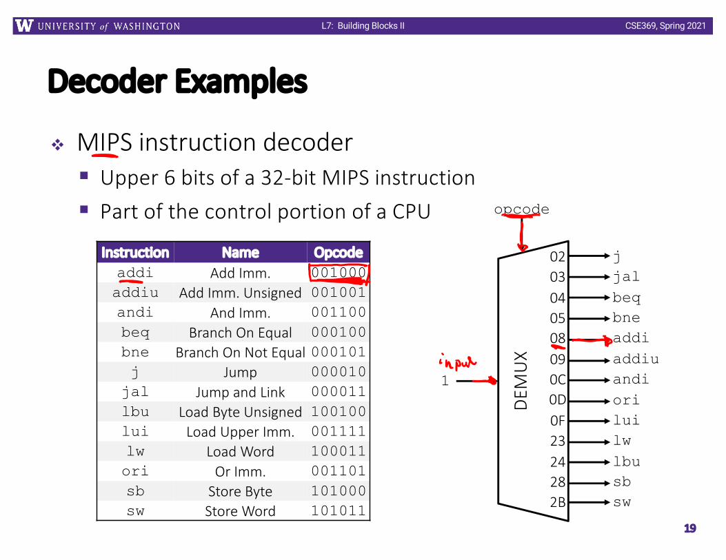
Decoder Examples
v MIPS instruction decoder§ Upper 6 bits of a 32-bit MIPS instruction§ Part of the control portion of a CPU
19
Instruction Name Opcodeaddi Add Imm. 001000addiu Add Imm. Unsigned 001001andi And Imm. 001100beq Branch On Equal 000100bne Branch On Not Equal 000101j Jump 000010
jal Jump and Link 000011lbu Load Byte Unsigned 100100lui Load Upper Imm. 001111lw Load Word 100011ori Or Imm. 001101sb Store Byte 101000sw Store Word 101011
DEM
UX
0203040508090C0D0F2324282B
jjalbeqbneaddiaddiuandioriluilwlbusbsw
opcode
1

CSE369, Spring 2021L7: Building Blocks II
TechnologyBreak
20

CSE369, Spring 2021L7: Building Blocks II
Outline
v Routing Elementsv Registers and Counters
21
CSE369, Spring 2021L7: Building Blocks II
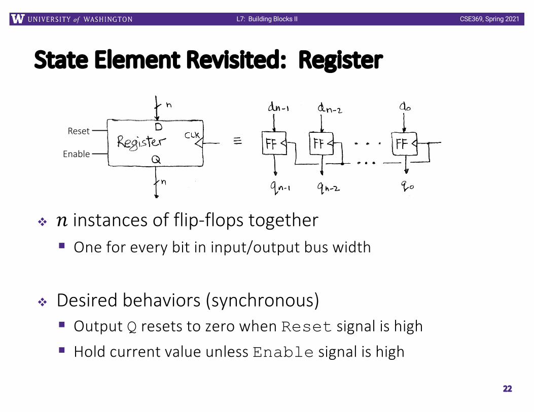
State Element Revisited: Register
v 𝑛 instances of flip-flops together§ One for every bit in input/output bus width
v Desired behaviors (synchronous)§ Output Q resets to zero when Reset signal is high § Hold current value unless Enable signal is high
22
Enable
Reset

CSE369, Spring 2021L7: Building Blocks II
Controlled Register
v Here using shorthand C (clock), R (reset), E (enable)
23
Reset Enable Action
0 0 Q = ___
0 1 Q = ___
1 0 Q = ___
1 1 Q = ___
D Flip-Flop
R
D Q
CE
CSE369, Spring 2021L7: Building Blocks II
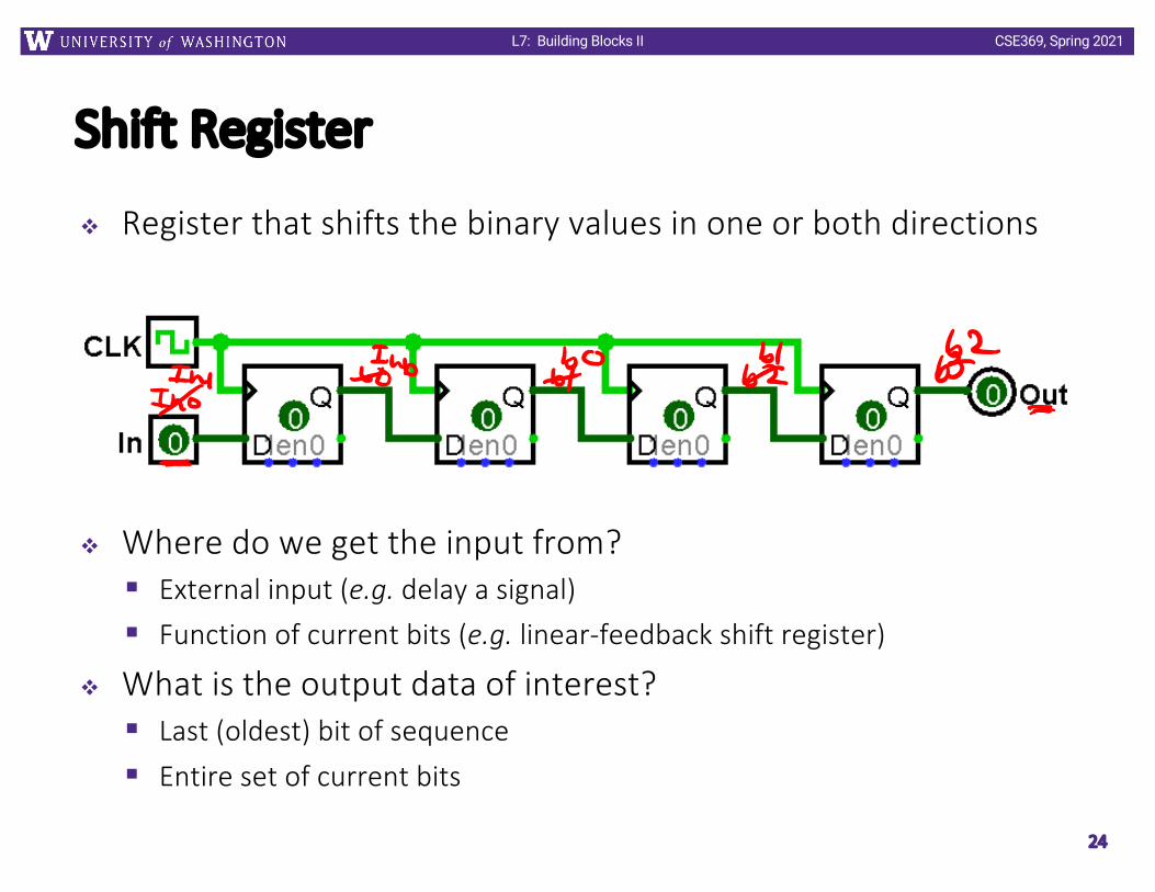
Shift Register
v Register that shifts the binary values in one or both directions
v Where do we get the input from?§ External input (e.g. delay a signal)§ Function of current bits (e.g. linear-feedback shift register)
v What is the output data of interest?§ Last (oldest) bit of sequence§ Entire set of current bits
24
CSE369, Spring 2021L7: Building Blocks II
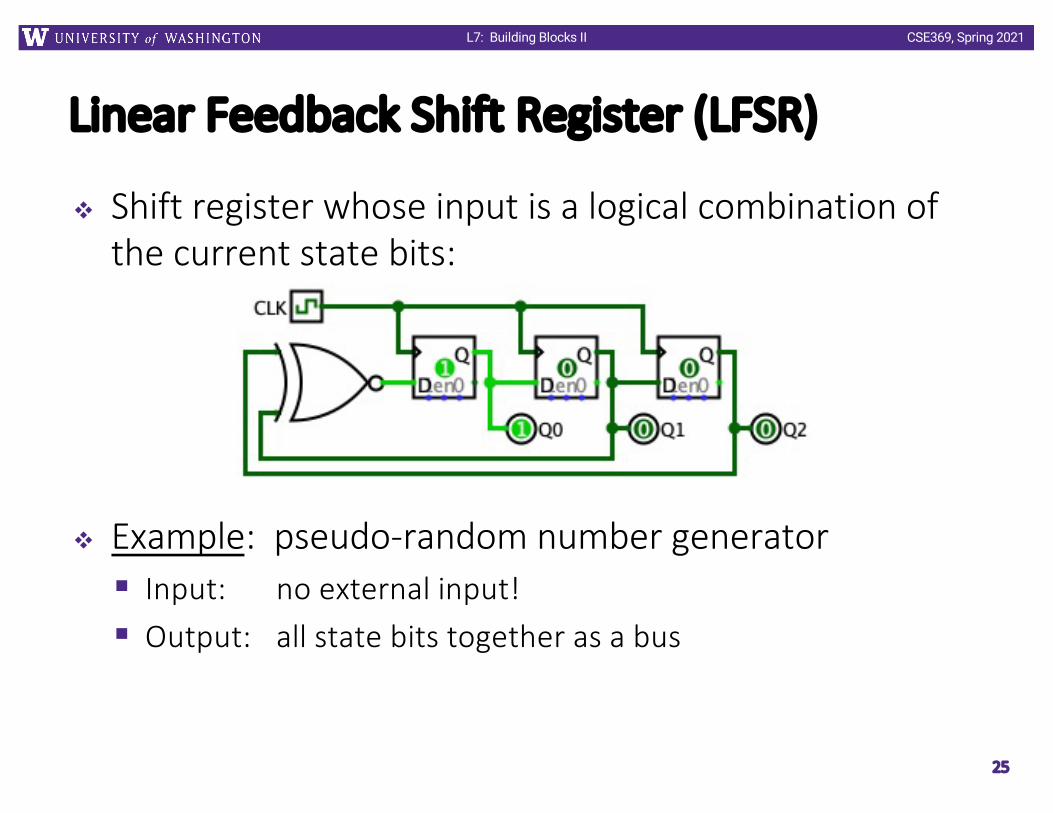
Linear Feedback Shift Register (LFSR)
v Shift register whose input is a logical combination of the current state bits:
v Example: pseudo-random number generator§ Input: no external input!§ Output: all state bits together as a bus
25
CSE369, Spring 2021L7: Building Blocks II
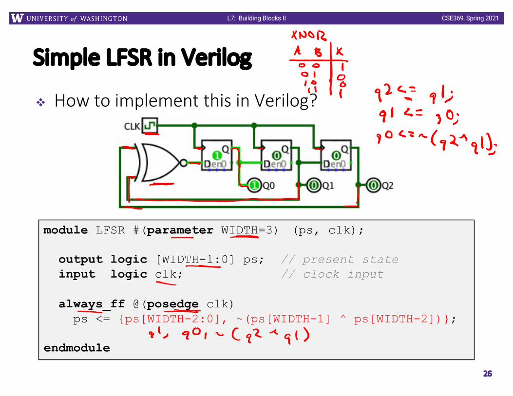
Simple LFSR in Verilog
v How to implement this in Verilog?
26
module LFSR #(parameter WIDTH=3) (ps, clk);
output logic [WIDTH-1:0] ps; // present stateinput logic clk; // clock input
always_ff @(posedge clk)ps <= {ps[WIDTH-2:0], ~(ps[WIDTH-1] ^ ps[WIDTH-2])};
endmodule

CSE369, Spring 2021L7: Building Blocks II
Counters
v A register that goes through a specific state sequence§ More general than what you typically think of as a “counter”
v Examples:§ n-bit Binary Counter: counts from 0 to 2N-1 in binary§ Up Counter: Binary value increases by 1§ Down Counter: Binary value decreases by 1
v 3-bit binary up counter state diagram:
27

CSE369, Spring 2021L7: Building Blocks II
LFSR Revisited
v A LFSR is also a counter!§ The logical combination determines the state sequence
v State diagram:
28

CSE369, Spring 2021L7: Building Blocks II
Binary Up-Counter Implementation
29
P2 P1 P0 N2 N1 N00 0 00 0 10 1 00 1 11 0 01 0 11 1 01 1 1
N2 00 01 11 10
0
1
N1 00 01 11 10
0
1
N0 00 01 11 10
0
1
D QDffCLK
D QDffCLK
D QDffCLK
CSE369, Spring 2021L7: Building Blocks II
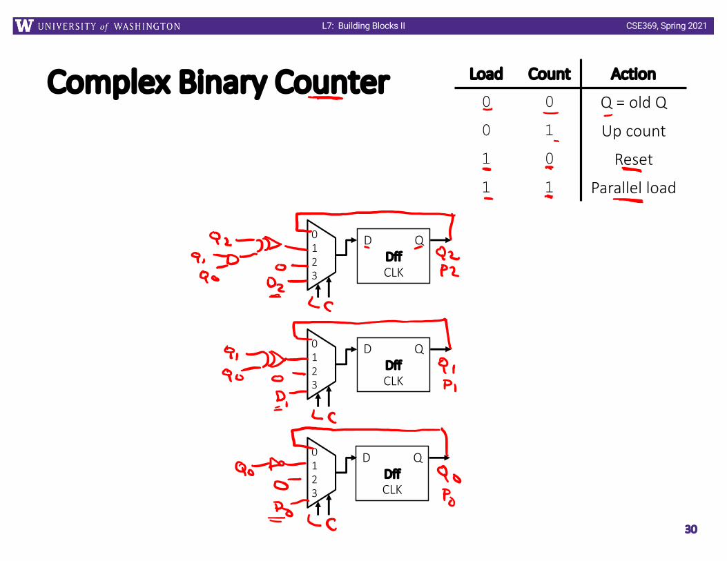
Complex Binary Counter
30
D QDffCLK
0123
D QDffCLK
0123
D QDffCLK
0123
Load Count Action
0 0 Q = old Q
0 1 Up count
1 0 Reset
1 1 Parallel load

CSE369, Spring 2021L7: Building Blocks II
Up Counter in Verilog (no load)
31
module upcounter #(parameter WIDTH=8)(out, enable, reset, clk);
output logic [WIDTH-1:0] out;input logic enable, reset, clk;
always_ff @(posedge clk) beginif (reset)
out <= 0;else if (enable)
out <= out + 1;end
endmodule