Embed Size (px)
Citation preview

DORMA Installation ManualTerminal L6L
F1
F3F4
F5F6
F21
3
4
5
26
8
9
0
7,
:
Esc
±
F7
F9F10
F11F12
F8

L6L 2. Assembly
2
L6L Table of contents
Contents
1. General . . . . . . . . . . . . . . . . . . . . . . . . . . . . . . . . . 3
1.1 Preface . . . . . . . . . . . . . . . . . . . . . . . . . . . . . . . . 4
1.2 Intended Use . . . . . . . . . . . . . . . . . . . . . . . . . . . . 4
1.3 Safety instructions and warnings . . . . . . . . . . . . . . 4
1.4 Further Source of Information . . . . . . . . . . . . . . . . 5
1.5 Disposal . . . . . . . . . . . . . . . . . . . . . . . . . . . . . . . 5
1.6 Functional principle . . . . . . . . . . . . . . . . . . . . . . . 5
1.7 Components supplied . . . . . . . . . . . . . . . . . . . . . . 6
1.8 Assembly accessories (optional) . . . . . . . . . . . . . . . 6
2. Assembly . . . . . . . . . . . . . . . . . . . . . . . . . . . . . . . . 7
2.1 Terminal design . . . . . . . . . . . . . . . . . . . . . . . . . . 7
2.2 Casing variants . . . . . . . . . . . . . . . . . . . . . . . . . . . 7
2.3 Dimensions . . . . . . . . . . . . . . . . . . . . . . . . . . . . . 8
2.4 Opening and closing the terminal . . . . . . . . . . . . . . 9
2.5 Assembly preparations . . . . . . . . . . . . . . . . . . . . 10
2.6 Assembly of flat casing . . . . . . . . . . . . . . . . . . . . 11
2.7 Assembly of deep casing . . . . . . . . . . . . . . . . . . . 12
2.8 Assembly using a wedge . . . . . . . . . . . . . . . . . . . 13
3. Connection variants . . . . . . . . . . . . . . . . . . . . . . . 14
3.1 External connections . . . . . . . . . . . . . . . . . . . . . . 14
3.2 Power supply . . . . . . . . . . . . . . . . . . . . . . . . . . . 14
3.3 Emergency power supply (optional) . . . . . . . . . . . . 16
3.4 LAN interface . . . . . . . . . . . . . . . . . . . . . . . . . . . 17
3.5 RS485/RS232 interface (sub-interface) . . . . . . . . 18
3.6 RS485/RS232 interface (host interface) . . . . . . . . 19
3.7 Sub-bus interface . . . . . . . . . . . . . . . . . . . . . . . . 20
3.8 Relay outputs (door opener) . . . . . . . . . . . . . . . . 21
3.9 Digital inputs . . . . . . . . . . . . . . . . . . . . . . . . . . . 21
4. Setup . . . . . . . . . . . . . . . . . . . . . . . . . . . . . . . . . . 22
4.1 Visual displays . . . . . . . . . . . . . . . . . . . . . . . . . . 22
4.2 Reader Settings . . . . . . . . . . . . . . . . . . . . . . . . 23
4.3 Memory expansion . . . . . . . . . . . . . . . . . . . . . . 23
5. Maintenance . . . . . . . . . . . . . . . . . . . . . . . . . . . . . 24
5.1 Maintenance and troubleshooting . . . . . . . . . . . . . 24
5.1.1 Fuses . . . . . . . . . . . . . . . . . . . . . . . . . . . . . . . 24
5.1.2 General information on changing the battery . . . 25
5.1.3 Replacing the back-up battery . . . . . . . . . . . . . 25
5.1.4 Reset button . . . . . . . . . . . . . . . . . . . . . . . . . . 25
6. EU Declaration of conformity . . . . . . . . . . . . . . . . . 26
7. Technical data . . . . . . . . . . . . . . . . . . . . . . . . . . . 29

L6L 2. Assembly
3
L6L 1. General
The information provided in these assembly instructions may be modified without prior notification. All previous versions cease to be valid with the publication of these instructions.
The information in these assembly instructions has been compiled to the best of our knowledge and in good faith. DORMA Time + Access GmbH accepts no liability for the correctness and completeness of the details provided.
In particular, DORMA Time + AccessGmbH cannot accept liability for any consequential damages due to incorrect or incomplete information.
The recommendations for installation provided in this manual are based on favourable basic conditions being present.
DORMA Time + Access GmbH accepts no liability for the perfect functioning of the L6L in external, non-system environments.
Despite every effort to prevent mistakes, they can never be completely avoided. Therefore, we would be grateful to receive notification of any errors or omissions.
DORMA Time + Access GmbH accepts no liability for the information included in this document being free of pro-tected third party rights. DORMA Time + Access GmbH does not provide any licences to its own or to third party patents or other protected rights with this document.
It is not permitted to print, reproduce or to pass this manual, or parts thereof, to third parties, other than for your own use, without the approval of DORMA Time + Access GmbH.
All rights reserved.DORMA Time + Access GmbHPostfach 21 01 8553156 Bonnhttp://www.dorma-time-access.deE-Mail [email protected]
© Copyright 2011 by DORMA Time + Access GmbH
Z.-Nr.: 1035G-00-B1aVersion: 10/14 V2.60

L6L 1. General
4
1.1 Preface
This installation manual is intended to assist you in connec-ting and commissioning the L6L.
1.2 Intended Use
The device is used as a time recording and access controlterminal.Further details are described in chapter 1.6.Any other use than that indicated is not permitted!
1.3 Safety instructions and warningsThis device has been constructed and tested in accordance with the relevant current technological regulations. It left the factory in perfect condition in terms of technological safety and reliability. To maintain this condition and to ensure risk-free operation, the instructions and warnings given in this assembly guide must be observed by the user.
• The device may only be used for the purpose intended by the manufacturer.
• The installation and assembly of electrical devices may only be carried out by an electrical engineer.
• Before opening the unit, always switch off the power supply and verify that the device is free of voltage by performing a measurement.
• During assembly, please ensure that the requirements laid down in the relevant device safety standard for the unit are not negatively affected, as this would reduce the safety level of the unit.
• Before switching on, ensure that the operating and control voltages connected do not exceed the permissible values in accordance with the technical data.
• This unit conforms to EN 60950-1 equipment variants: 230/115VAC - safety class I 24VAC/DC - safety class III
• The units must be operated with safety extra low voltage (SELV)!
Electromagnetic compatibility:• The unit is designed for use in residential, business and
commercial areas and conforms to EN 61000-6-2 and 61000-6-3.
• The PCB is at risk from electrostatic discharge and the relevant precautionary measures should be observed (earthing, etc.).
Caution
• The units may only be operated when fully assembled.
• The locking screws on unassigned connection terminals should be screwed in as far as they will go.
• If it is safe to assume that danger-free operation is no longer possible, take the unit out of operation and secure against accidental use.
• If the failure or malfunctioning of the unit may result in injury to persons or animals, or in damage to works equipment, this must also be prevented using additional safety measures (limit switch, safety devices, etc.).
• Switch off the power supply before opening the unit.

L6L 2. Assembly
5
L6L 1. General
1.6 Functional principle
The L6 terminals are designed for time recording and access control.The terminal has a keyboard that can be used to operate various queries and functions in the system. The result is shown visually on a two-line display.
The identity and the rights of the user are determined using a badge and where applicable by entering a PIN.The badge data is queried by the integrated reader.
The evaluation is performed in the terminal. The result is acknowledged using an acoustic signal where applicable.
The access authorisation profiles and the time recording data for the staff members are also stored locally. This makes safe offline operation possible. The memory capacity is designed for a minimum of 1,000 staff members.
The memory capacity can be extended using a Compact Flash memory card.
The data stored in the RAM is buffered by a lithium battery in the event of a power failure.
To ensure operation during a short-term power cut, the terminal can be fitted with an optional internal emergency power supply.
In addition, the terminal has two relay outputs and three digital inputs for control and monitoring functions.
The connection to a host can be realised via either an LAN interface or an RS485 interface.For connecting sub-devices there is a DCW and an RS485 bus available.
1.4 Further Sources of InformationFurther documents are available on request.
DORMA EAC Hardware ManualSpecifications for planning attendance recording and access control systems with our wired components.
1.5 DisposalThe device was manufactured using recyclable materials and components.When disposing of the device and the packaging, please ensure environmentally friendly recycling.
Information for EU CountriesEuropean Directive 2002/96 EC applies to this device. This means that this product must not be disposed of withnormal household waste. We, the manufacturer, will take back our electric and electronic products and dispose of them for you free of charge. Correct disposal of your old equipment protects people and the environment from possible harmful consequences.
BatteriesThe device contains an integrated lithium battery and, where applicable, a nickel-metal hydride rechargeable bat-tery.Defective or used batteries and accumulators must be recy-cled in compliance with European Directive 2006/66/EC.
You should find out about local regulations regarding the separate disposal of batteries.Correct disposal of batteries protects people and the envi-ronment from possible harmful consequences.
L6L 2. Assembly
6
L6L 1. General
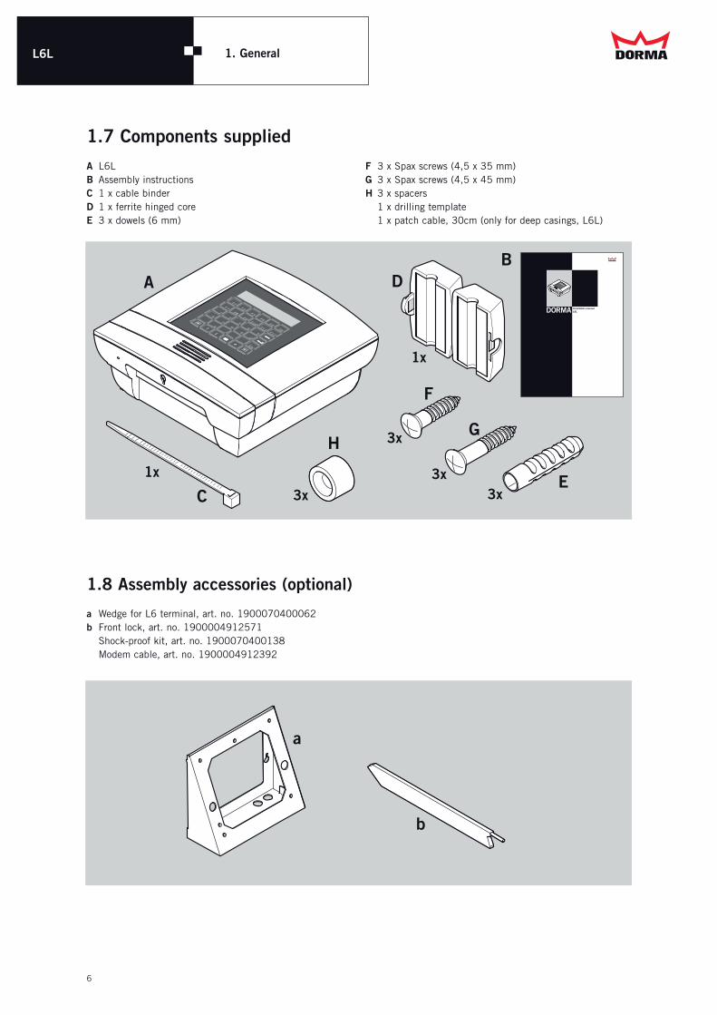
1.7 Components suppliedA L6L B Assembly instructionsC 1 x cable binderD 1 x ferrite hinged coreE 3 x dowels (6 mm)
F 3 x Spax screws (4,5 x 35 mm)G 3 x Spax screws (4,5 x 45 mm)H 3 x spacers 1 x drilling template 1 x patch cable, 30cm (only for deep casings, L6L)
A
H
D
1x
B
E
G
3x3x
F
3x
3x
DORMA Installation manualL6L
C1x
F1
F3F4
F5F6
F21
3
4
5
26
8
9
0
7,
:
Esc
±
F7
F9F10
F11F12
F8
F1
F3F4
F5F6
F21
3
4
5
26
8
9
0
7,
:
Esc
±
F7
F9F10
F11F12
F8
1.8 Assembly accessories (optional)
a Wedge for L6 terminal, art. no. 1900070400062 b Front lock, art. no. 1900004912571 Shock-proof kit, art. no. 1900070400138 Modem cable, art. no. 1900004912392
a
b

L6L 2. Assembly
7
L6L 2. Assembly
2.1 Terminal design
The terminal consists of the top casing section, bottom casing section, and the preassembly plate.The models are explained in the next chapter.
F1
F3F4
F5F6
F21
3
4
5
26
8
9
0
7,
:
Esc
±
F7
F9F10
F11F12
F8 Top section
Bottom section
Preassembly plate
F1 F3 F4 F5 F6F2
1 3 4 52
6 8 9 07
, : Esc±
F7 F9 F10 F11 F12F8
F1 F3 F4 F5 F6F2
1 3 4 52
6 8 9 07
, : Esc±
F7 F9 F10 F11 F12F8
F1 F3 F4 F5 F6F2
1 3 4 52
6 8 9 07
, : Esc±
F7 F9 F10 F11 F12F8
No-touch reader (PXL) Plug-in reader (ESL) Push-through reader (DZL)
2.2 Casing variants
Top sections

L6L 2. Assembly
8
L6L 2. Assembly
268.6 mm 268.6 mm
64
.5 m
m
10
4 m
m2
68
.6 m
m
26
8.6
mm
F1 F3 F4 F5 F6F2
1 3 4 52
6 8 9 07
, : Esc±
F7 F9 F10 F11 F12F8
F1 F3 F4 F5 F6F2
1 3 4 52
6 8 9 07
, : Esc±
F7 F9 F10 F11 F12F8
F1
F3F4
F5F6
F21
3
4
5
26
8
9
0
7,
:
Esc
±
F7
F9F10
F11F12
F8
F1
F3F4
F5F6
F21
3
4
5
26
8
9
0
7,
:
Esc
±
F7
F9F10
F11F12
F8
61.5 mm 101 mm
Bottom sections
Flat surface-mounting (AF)For PX and DZL fronts
Deep surface-mounting (AT)For ESL fronts, and terminals with emergency power supply
2.3 Dimensions

L6L 2. Assembly
9
2.4 Opening and closing the
terminal
The unlocking mechanism is accessed through the hole on the underside of the terminal. If there is a lock in this hole, remove the lock first.To open the casing you need a rod-shaped tool (such as a screwdriver) which you insert through the unlocking hole. Using strong pressure, increasing in force on the unlocking piece on the inside, the casing will spring open. (see right)Then pull the top casing section vertically towards the wall as far as it will go to remove it from the lower casing sec-tion. Then swivel the top casing section to the left.
To close the unit, follow the same steps in the reverse order.
When working on the open casing, it is advisable to lock the front using the front locking catch. This tool can also be used to open the terminal.
Please note the following points:• Do not allow the flat-band cable between the top and
bottom casing sections to be trapped when closing.• The unlocking piece must be positioned to fit the guide.• The top casing section can only be positioned parallel to
the bottom section based on the design. When the top casing section is positioned on the bottom casing section, the unit can be closed using even pressure on the right and left-hand sides of the top casing section.This means that an audible ‘click’ can be heard when the unit is closed correctly.
F1
F3F4
F5F6
F21
3
4
5
26
8
9
0
7,
:
Esc
±
F7
F9F10
F11F12
F8
F1
F3F4
F5F6
F21
3
4
5
26
8
9
0
7,
:
Esc
±
F7
F9F10
F11F12
F8
d

L6L 2. Assembly
10
2.5 Assembly preparations
GeneralWhen planning the installation site for the terminal, the required space specified in the diagram opposite must be provided. This space is necessary to ensure problem-free operation and sufficient room for servicing work. The installation height specified is recommended to provide persons of average height the optimum operation and view of the display.
If it is necessary, or desired, that a different height is used, an assembly wedge piece should be used.
Once the installation site has been determined, the cables should be laid first of all. Specifications on the planning and installation of time systems and access systems using our components are described in the General Installation Guidelines.
The following assembly types are possible:
Deep casing• Flush-fit cabling (standard)• Flush-fit cabling, connection of LAN and 230V using sockets
Flat casing• Flush-fit cabling (standard)• Surface wiring (supply line at bottom) The application surface of the terminal is used here. Caution: not possible for all terminals!
Wedge (for deep and flat casings)• Flush cabling• Surface wiring (supply line at bottom)
For each installation type, the relevant specifications on the position of the cable infeed and cable length must be observed.
L6L terminal with contactless readersTo prevent interference between devices, you must not install two devices with contactless readers closer to each other than the minimum specified distance. This distance should always be greater than 50 cm.
min.165 mm
min.165 mm
appr
ox.
14
50
mm
F1 F3 F4 F5 F6F2
1 3 4 52
6 8 9 07
, : Esc±
F7 F9 F10 F11 F12F8
Installation wedge piece

L6L 2. Assembly
11
2.6 Assembly of flat casing
Flush cablingOnce the preparatory work is complete, the pre-assembly plate can be fitted to the wall.
To do this, the three holes for the fixing screws must be drilled according to the drilling template included.
Before drilling, ensure that you will not be able to damage any cables or similar located underneath the plaster.
The cables are laid through the knock-out sections on the pre-assembly plate.The data cables (RS485/DCW) must be stripped from approx. 15mm after the wall opening.The shielding is shortened to approx. 10mm and clamped underneath the clips.
The clips are intended for connecting the data line shielding and are not used for strain relief.
The wires are then shortened to the required length and connected to the screw terminals (on the terminal printed card). The transformer is only fitted for the 230V models.
The cables are then inserted through the rear wall of the terminal and the terminal is screwed onto the pre-assembly plate using the three fixing screws.
Area for cable outlet
Contour of pre-assembly plate
ø6
164.5
14
2.5
27
.7
appr
ox.
15
00
Lower casing edge
Top edge of finished floor
ø6
ø6
Transformer

L6L 2. Assembly
12
2.7 Assembly of deep casing
Flush cablingOnce the preparatory work is complete, the pre-assembly plate can be fitted to the wall.
To do this, the three holes for the fixing screws must be drilled according to the drilling template included.
Before drilling, ensure that you will not be able to damage any cables or similar located underneath the plaster.
The cables are laid through the knock-out sections on the pre-assembly plate.
The data cables (RS485/DCW) must be stripped from approx. 20mm after the wall opening.The shielding is shortened to approx. 10mm and clamped underneath the clips.
The clips are intended for connecting the data line shielding and are not used for strain relief.
The wires are then shortened to the required length and connected to the screw terminals (on the terminal printed card).
The transformer is only fitted for the 230V models.
If the terminal is being installed using a flush-fit box, the terminal must be fitted at the correct distance using the spacer pieces included in the accessories kit.
The 230V connection is then made using a shock-proof connection cable.
This cable in included in the accessories.The patch cable included is used to connect the LAN. The cables are then inserted through the rear wall of the terminal and the terminal is screwed onto the pre-assembly plate using the three fixing screws.
ø6
Area for cable outlet
171
31.2
14
2.5
Lower casing edge
Top edge of finished floor
35
.9
appr
ox.
15
00
15
4.8
ø6
ø6
L6L 2. Assembly
13
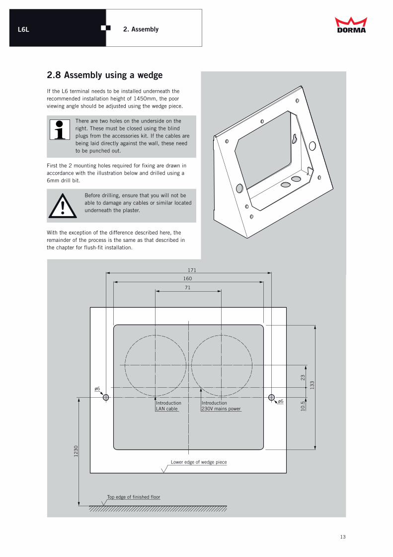
2.8 Assembly using a wedge
If the L6 terminal needs to be installed underneath the recommended installation height of 1450mm, the poor viewing angle should be adjusted using the wedge piece.
There are two holes on the underside on the right. These must be closed using the blind plugs from the accessories kit. If the cables are being laid directly against the wall, these need to be punched out.
First the 2 mounting holes required for fixing are drawn in accordance with the illustration below and drilled using a 6mm drill bit.
Before drilling, ensure that you will not be able to damage any cables or similar located underneath the plaster.
With the exception of the difference described here, the remainder of the process is the same as that described in the chapter for flush-fit installation.
IntroductionLAN cable
Introduction230V mains power
12
30
171
160
71
Lower edge of wedge piece
Top edge of finished floor
13
3
23
10
.5
ø6
ø6

L6L 3. Connection variants
3.1 External connections
All external connections are on the basic TP4 card, and if available, also on the rechargeable battery card.
ST504Relay2
ST505Relay1
ST6
01
Sub
Bus
ST506Power
ST503Digital inputs
LAN
ST507RS485
ST508RS232
3.2 Power supply
24V-TerminalsThe power supply of the L6L is provided via a plug connector ST506. With the 24V terminals a voltage with 16V to 36V DC direct voltage or 16V to 24V AC alternating current must be connected here.
230V-TerminalsWith the 230V terminals, the power supply is provided via the transformer on the preassembly plate. The connection may only be carried out by a qualified electrical engineer.
PowerST506
24
V
0V
Shi
eldi
ng

L6L 2. Assembly
15
230 V terminals
a) Permanent connection (standard)In the case of 230 V terminals, power is supplied via the transformer on the preassembly plate.
The device is designed for a permanent con-nection to the power supply circuit only. It must be connected by a qualified electri-cian only.
The power supply circuit for this device requires a suitable, easily accessible power isolating device with a minimum contact gap of 3 mm and a fuse element to protect against short circuits, both already provided on site.
The earth conductor must be connected.
b) Plug-in connection (deep casing only)An earthing connection cable is used to connect to the power supply circuit. This cable is available as an accessory.
Use the enclosed clip to install the earthing connection cable and ensure that is not tensioned.
The earth conductor must be connected.
earthconductor
230V
18Vtransformer
230V-Power cable
230V
18Vtransformer
transformer18V
230V
230V-Power cable
earthconductor
earth conductor
flat housing
deep casing
Plug-in connection (deep casing only)
3. Connection variants

L6L 2. Assembly
16
3.3 Emergency power supply
(optional)
Terminals with integrated emergency power supply also have a rechargeable battery and a rechargeable battery card.
The voltage is connected here on the ST201 on the rechar-geable battery card and forwarded to the basic TP4 card via a connection cable.
The behaviour in the event of a power failure depends on the configuration of the terminal.
Either the terminal goes into standby mode after an adju-stable time and the terminal is reactivated by pressing the E-key on the keyboard, or the terminal remains switched on permanently.
In emergency power mode DCW sub-devices can also be supplied as well. If the terminal is in standby mode, it can also be activated by an entry on a sub-reader.
When using the rechargeable battery card in an L6R, only DCW sub-devices can be connected.
Pow
erS
T20
1
24V
0VShielding
3. Connection variants

L6L 2. Assembly
17
L6L 3. Connection variants
3.4 LAN interface
The LAN interface conforms to Ethernet standard IEEE 802.3.The CAT5 cable with RJ45 plug is inserted directly into the LAN connection at the top right of the basic module.
The ferrite hinged core included in the accessories kit must be clamped around the LAN cable.
LAN
C
Ferri
te
hinge
d core

L6L 2. Assembly
18
L6L
The RS485/232 interface transmission type can be switched over (factory-set status: RS485).
RS485 – ST507 (SubBus)RS232 – ST508 (for servicing work, if applicable)
If the L6L is the first or the last bus subscriber, the bus connection resistor must be connected.To do this, move the two-pole slider switch SW602 to “ON”. (Factory-set status: switched on).
Communication with the sub-devices is facilitated via the RS485 interface.Up to 31 RS485 sub-devices, including a maximum of 16 readers can be connected.Please note here that the total power consumption of the sub-terminals does not exceed the output of the terminal or external power pack.
RS232RS485
SW601Interface changeover switch
OFF ON
12
SW602RS485 terminating resistors
3. Connection variants
3.5 RS485/RS232 interface as sub-bus interface
RS485: For old devices (e.g. VTxx, M6-Box, M6I, M6T, L6I) the pin configuration is inverted.For an exchange the connection must occur in reverse. (A to B(-) and B to A(+))
ST508
RX
TXGN
D
RS232ST507
B(-)
A(+)
RS485

L6L 2. Assembly
19
The RS485/232 interface transmission type can be switched over (factory-set status: RS485).
RS485 – ST507 (host, 2-wire)RS232 – ST508 (host, modem)
If the L6L is the first or the last bus subscriber, the bus connection resistor must be connected.To do this, move the two-pole slider switch SW602 to “ON”. (Factory-set status: switched on).
If the connection to the host is being made via a modem, the modem cable (art. no. 1900004912392) is connected to ST508.
RS485: For old devices (e.g. VTxx, M6-Box, M6I, M6T, L6I) the pin configuration is inverted.For an exchange the connection must occur in reverse. (A to B(-) and B to A(+))
RS232RS485
SW601Interface changeover switch
OFF ON
12
SW602RS485 terminating resistors
ST508 Signal Farbe
Pin 16 GND white
Pin 17 Tx brown
Pin 18 Rx green
Host via modem
3. Connection variants
3.6 RS485/RS232 interface as host interface
ST508
RX
TXGN
D
RS232ST507
B(-)
A(+)
RS485
L6L 2. Assembly
20
ST6
01
Sub
Bus
ST202DCW SubBus
ST204DCW int.
ST203Power int.
ST201Power
Rechargeable battery card
3. Connection variants
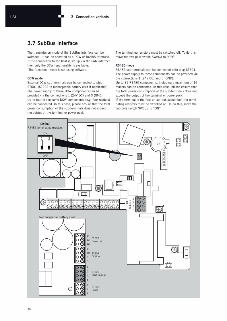
3.7 SubBus interface
The transmission mode of the SubBus interface can be switched. It can be operated as a DCW or RS485 interface. If the connection to the host is set up via the LAN interface then only the DCW functionality is available. The functional mode is set using software.
DCW modeExternal DCW sub-terminals can be connected to plug ST601 (ST202 to rechargeable battery card if applicable).The power supply to these DCW components can be provided via the connections 1 (24V DC) and 3 (GND).Up to four of the same DCW components (e.g. four readers) can be connected. In this case, please ensure that the total power consumption of the sub-terminals does not exceed the output of the terminal or power pack.
The terminating resistors must be switched off. To do this, move the two-pole switch SW603 to “OFF”.
RS485 modeRS485 sub-terminals can be connected onto plug ST601. The power supply to these components can be provided via the connections 1 (24V DC) and 3 (GND).Up to 31 RS485 components, including a maximum of 16 readers can be connected. In this case, please ensure that the total power consumption of the sub-terminals does not exceed the output of the terminal or power pack.If the terminal is the first or last bus subscriber, the termi-nating resistors must be switched on. To do this, move the two-pole switch SW603 to “ON”.
OFF
ON
1 2
SW603RS485 terminating resistors
L6L 2. Assembly
21
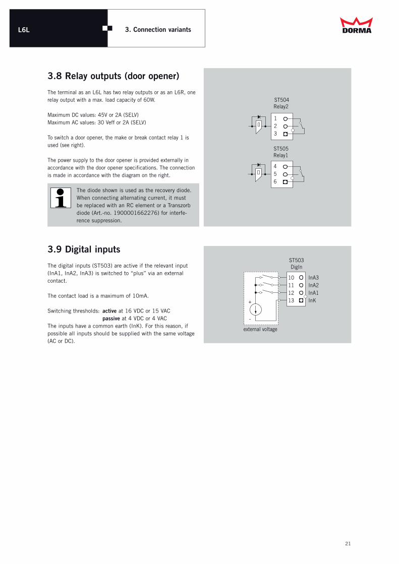
3.8 Relay outputs (door opener)
The terminal as an L6L has two relay outputs or as an L6R, one relay output with a max. load capacity of 60W. Maximum DC values: 45V or 2A (SELV)Maximum AC values: 30 Veff or 2A (SELV)
To switch a door opener, the make or break contact relay 1 is used (see right).
The power supply to the door opener is provided externally in accordance with the door opener specifications. The connection is made in accordance with the diagram on the right.
The diode shown is used as the recovery diode.When connecting alternating current, it must be replaced with an RC element or a Transzorb diode (Art.-no. 1900001662276) for interfe-rence suppression.
3.9 Digital inputs
The digital inputs (ST503) are active if the relevant input (InA1, InA2, InA3) is switched to “plus” via an external contact.
The contact load is a maximum of 10mA.
Switching thresholds: active at 16 VDC or 15 VAC passive at 4 VDC or 4 VACThe inputs have a common earth (InK). For this reason, if possible all inputs should be supplied with the same voltage (AC or DC).
3. Connection variants
ST504Relay2
ST505Relay1
54
6
21
3
+
-
ST503DigIn
external voltage
1110
1213
InA2InA3
InA1InK

L6L 2. Assembly
22
4.1 Visual displays
LED 301
on
Meaning
System runHardware and software in operation
LED 302
green
off
red
Meaning
Input voltage over the minimum permissible voltage.
Input voltage under the minimum permissible voltage.
A manual reset has been triggered
LED 401
flashing
Meaning
Data is being sent or received
LED 402
on
Meaning
Remote terminal present
LED 601
on
Meaning
Data is being sent or received
LED 302Supply Voltage
LED 301Internal Voltage
LED 601SubBus
LED 401LAN Rx/Tx
LED 402LAN Link
4. Commissioning

L6L 2. Assembly
23
4. Commissioning
SW101
6 Configuration protection
off off
on active
4.2 Reader settingsHitag (PX10)Legic advant-Leser (PX51)Mifare DESfire-Leser (PX71)
SW101
1 2 3 4 5 6 7 8
Function unused 1) 2) 3)
1) Configuration protection When configuration protection is activated, the configuration cannot be changed or deleted.
SW101
1 2 3 4 5 6 7 8
Function unused Reader Function unused
SW101Reader Function
4 5 6
off off off Indala-Trovan (Kombi)
off off on Indala (Flexpass)
off on off Trovan (TIMAC)
off on on free
on off off Trovan current customer (TIMAC)
on off on free
on on off Trovan (IPEV)
on on on free
XX
XXXXXXXXXXXX3801###
SW101
Number Reader
3801415 HITAG (PX10)
3801400 Legic advant (PX51)
3801202 Mifare DESFire (PX71)
Indala-Trovan (PX15)
3801261########
## ##
SW101
Number Reader
3801261 Indala-Trovan (PX15)
The configuration protection function is only available with firmware V3.30 or later.
2) Interface
3) unused
Switch 6 is set ex works, and its position should not be changed. An incorrect setting can make the reader unusable!
Configuration protection may only be deactivated if the "Load IdendAssembler" system parameter is activated in DORMA MATRIX.
SW101
7 Interface
off OMRON operation
on RENA operation

L6L 4. Commissioning
24
4.3 Additional memory
The terminal is designed for 1,000 employees without requiring additional memory. With an optional memory upgrade, the capacity can be increased to 10,000 or 200,000 employees.
The memory upgrade can be ordered as an accessory.
Art. No. Description
1900070400134 Upgrade 1000 / 10.000 EMP
1900070400135 Upgrade 1000 / 200.000 EMP
1900070400136 Upgrade 10.000 / 200.000 EMP
Before the card is inserted in or replaced, the power supply must be switched off.

L6L 2. Assembly
25
5.1
5.1.1 FusesIn the event that the fuse (SI301 � base card, SI201 � rechargeable card) needs to be replaced, there is a spare fuse at the bottom right of the base module.
The fuse can be re-ordered using art. no. 1900001797487 (Littlefuse type 0454.002, 2A).The use of other fuses is not permissible.
Rechargeable card (optional)
Si2
01
5. Maintenance
5.1 Maintenance and troubleshooting
L6L 2. Assembly
26
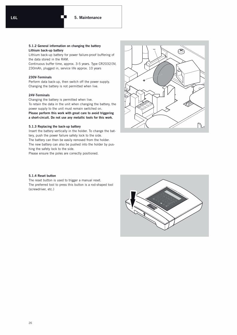
5.1.2 General information on changing the batteryLithium back-up batteryLithium back-up battery for power failure-proof buffering of the data stored in the RAM.Continuous buffer time, approx. 3-5 years. Type CR2032/3V, 230mAh, plugged in, service life approx. 10 years
230V-TerminalsPerform data back-up, then switch off the power supply. Changing the battery is not permitted when live.
24V-TerminalsChanging the battery is permitted when live.To retain the data in the unit when changing the battery, the power supply to the unit must remain switched on.Please perform this work with great care to avoid triggering a short-circuit. Do not use any metallic tools for this work.
5.1.3 Replacing the back-up batteryInsert the battery vertically in the holder. To change the bat-tery, push the power failure safety lock to the side. The battery can then be easily removed from the holder.The new battery can also be pushed into the holder by pus-hing the safety lock to the side.Please ensure the poles are correctly positioned.
5.1.4 Reset buttonThe reset button is used to trigger a manual reset.The preferred tool to press this button is a rod-shaped tool (screwdriver, etc.)
–
+
5. Maintenance
F1
F3F4
F5F6
F21
3
4
5
26
8
9
0
7,
:
Esc
±
F7
F9F10
F11F12
F8

L6LEG KonformitätserklärungEC Declaration of ConformityCE Déclaration de conformité
27
L6LEG KonformitätserklärungEC Declaration of ConformityCE Déclaration de conformité

L6L
28
EG KonformitätserklärungEC Declaration of ConformityCE Déclaration de conformité
L6LEG KonformitätserklärungEC Declaration of ConformityCE Déclaration de conformité
29

L6L 2. Assembly
30
We reserve the right to make technical modifications and improvements to promote the progress of our equipment.
L6L 6. Technical data
Technical data for L6L
Power supply16 V bis 36 VDC (SELV)16 V bis 24 VAC (SELV)230V AC / 50Hz (only for terminals with transformer)Emergency power supply (for terminals with rechargeable battery) 14V/1.1Ah
Power consumption without sub-terminals: 8W (approx. 350mA/24V)with sub-terminals: max. 8W (approx. 840mA/24V)
Data retention Power failure-proof buffering of the data stored in the RAM.
Internal readersThe following readers can be integrated:Push-through readerPlug-in readerNo-touch reader
Read distanceINDALA-TROVAN: max. approx. 8cmMIFARE, LEGIC, HITAG: max. approx. 4cm
Sub-terminals (DCW and RS485 bus)DCW: max. 4 units of the same type (e.g. 4x badge readers)RS485: max. 31 units, including max. 16 readers(The number of readers depends on the bus protocol and the terminal model)
Interfaces Host: 1x Ethernet 10/100Mbit (IEEE802.3u)SubBus: 1x RS485, 1x DCW
Outputs 2x relay load capacity: max. 60W, 2A45V DC (SELV)30Veff AC (SELV) Digital inputs3x optocouplers (plus-switching)Max. loading: 10mASwitching thresholds: active at 16 VDC or 15 VAC passive at 4 VDC or 4 VAC
Display and operating elements1x LC display with 2x 16 characters, back-lit1x acoustic signal transmitter1x reset button1x keyboard (various models possible)The functional principle depends on the software used.
Connection cableDue to the connection terminals, only lines with a max. cross-section of 1mm² can be connected.
Environmental conditionsOperating temperature range: -20°C to +50°CStorage temperature range: -20°C to +70°CHumidity range: 0 to 80%, non-condensing
General designEN 60 950-1, safety class IIIEN 60 950-1, safety class I (for 230V)
Protection ratingIP30
Resistance to interferenceEN 61000-6-2Immunity of devices in industrial operation
Interference emissionsEN 61000-6-3Interference emissions of devices in residential spaces
Dimensions268.6 x 268.6 x 64.5mm (WxHxD) (flat)268.6 x 268.6 x 104mm (WxHxD) (deep)
Casing colourGrey/blue RAL2208005
Weight:max. 4kg (depending on the casing and the fittings)
DORMA Time + Access GmbH Postfach 21 01 85 • D-53156 Bonn • Mainzer Straße 36-52 • D-53179 Bonn Tel. +49 (0) 2 28/85 54-0 • Fax +49 (0) 2 28/85 84-1 75 • www.dorma-time-access.de