Embed Size (px)
Citation preview
Grease Jockey® Installation and Operation Guide
Grease Jockey Installation and Operation Guide L30050
Table of Content
Subject Page
System Description 1
Component Description
Timer 2
Solenoid 2
Air Pumps 3
Modules 3
Meters and Tubing 4
Grease and Kits 4
Electric Pumps 5
Typical System Layout 6
Typical Bill of Materials 7
Installation Steps
1 - Pump Mounting 8
2 - Solenoid 8
3- Timer and Wiring 9
4 - Modules 9-11
5- Tubing 11
6- System Fill/Start 12
7 - Air Purge Lines 12
8 - Warranty Registration 13
PM Procedure 15
Troubleshooting 16-17
Parts List 18-20

Grease Jockey Installation and Operation Guide L30050
Page 1
Grease JOCkey sysTeM DesCrIPTION
The Grease Jockey® system is controlled by a timer, which activates either an air solenoid valve or an electric motor to drive a pump. The pump supplies grease into the main supply line for delivery to localized distribution modules.
These modules are made up of manifolds with metering valves and distribution lines for each lube point in that localized area. The meters are designed to dispense a precise amount of grease at each lube cycle. Meter size is chosen by a ratio of the smallest to largest lube point requirements in the system.
The pump must pressurize the system, then vent it to allow the metering valves to reset for the next cycle. A fluid grease is required to achieve proper flow and lubrication characteristics.
Grease Jockey Installation and Operation Guide L30050
Page 2
sysTeM COMPONeNTs
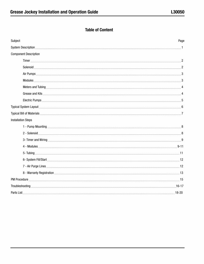
TIMer
The timer (Ref. Fig. 1) on an air operated pump system is a compact solid state device housed in a high impact resistant plastic enclosure. It has seven lube cycle interval settings from 1/2 to 6 hours, plus a test position and a manual run button.
The timer operates the system only while the vehicle's ignition is turned on. A memory function keeps track of elapsed-cycle-time even if the ignition switch is turned off. When the predetermined cycle time has elapsed, the timer signals the pump to initiate a lubrication cycle. If the vehicle's ignition is turned off before the interval is complete, the timer's memory "holds" the time count until the vehicle is restarted.
When the cycle-time dial is switched from one range to another, the manual run button should be pressed to initiate the new cycle time setting (otherwise, the new time is added to any time that remains from the previous lube cycle).
When rapid repetitive cycles are needed, turn ignition key to "ON", set the cycle-time dial to the "test" position, and press the manual run button. In this mode the timer signals the pump to cycle approximately once every minute. (45 seconds on and 15 seconds off). This rapid cycling continues as long as the timer remains in the "test" position. Always reset the timer dial to it's proper setting.
sOLeNOID
The air valve (Ref. Fig. 3) used with the air operated pump threads into the port on the bottom of the pump. It is a 3-way, normally closed, free venting valve available with either a 12 or 24 VDC 9 watt continuous duty rated coil. The coil is molded and potted with a 6" lead of 16 AWG wire and a weather tight (male) connector. The air valve has a 1/8" NPT inlet port and a 1/4" NPT male thread outlet port. The maximum operating pressure is 150 psi. The barbed connector is the exhaust port and should not be blocked. There is a manual test button located on the end above the electrical lead. A 22' wire harness with a weather tight (female) connector to mate with the solenoid is available (included with kits).
Figure 1 Figure 3
FIGure 2 reCOMMeNDeD TIMer seTTINGTimer setting Driving Conditions
0.5 or 1 hour Off Highway
1.5 or 2 hours Start + stop city, heavy salt, snow and ice, rough pavement, wet climate, heavy loads, dusty roads
3 hours Normal city or highway driving, normal climate, moderate loads
These are recommended settings only. Experience with individual applications will determine timer settings.
Grease Jockey Installation and Operation Guide L30050
Page 3
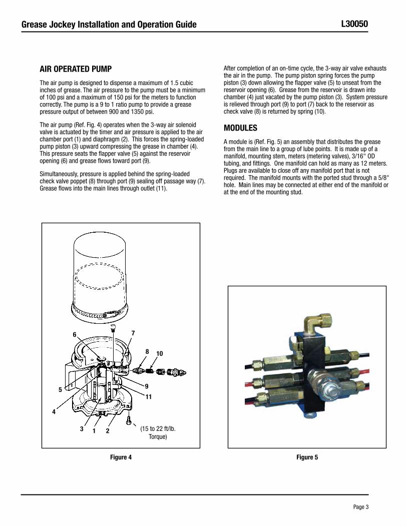
aIr OPeraTeD PuMP
The air pump is designed to dispense a maximum of 1.5 cubic inches of grease. The air pressure to the pump must be a minimum of 100 psi and a maximum of 150 psi for the meters to function correctly. The pump is a 9 to 1 ratio pump to provide a grease pressure output of between 900 and 1350 psi.
The air pump (Ref. Fig. 4) operates when the 3-way air solenoid valve is actuated by the timer and air pressure is applied to the air chamber port (1) and diaphragm (2). This forces the spring-loaded pump piston (3) upward compressing the grease in chamber (4). This pressure seats the flapper valve (5) against the reservoir opening (6) and grease flows toward port (9).
Simultaneously, pressure is applied behind the spring-loaded check valve poppet (8) through port (9) sealing off passage way (7). Grease flows into the main lines through outlet (11).
After completion of an on-time cycle, the 3-way air valve exhausts the air in the pump. The pump piston spring forces the pump piston (3) down allowing the flapper valve (5) to unseat from the reservoir opening (6). Grease from the reservoir is drawn into chamber (4) just vacated by the pump piston (3). System pressure is relieved through port (9) to port (7) back to the reservoir as check valve (8) is returned by spring (10).
MODuLes
A module is (Ref. Fig. 5) an assembly that distributes the grease from the main line to a group of lube points. It is made up of a manifold, mounting stem, meters (metering valves), 3/16" OD tubing, and fittings. One manifold can hold as many as 12 meters. Plugs are available to close off any manifold port that is not required. The manifold mounts with the ported stud through a 5/8" hole. Main lines may be connected at either end of the manifold or at the end of the mounting stud.
6 7
8 10
9
11
213
4
5
(15 to 22 ft/lb. Torque)
Figure 4 Figure 5
Grease Jockey Installation and Operation Guide L30050
Page 4
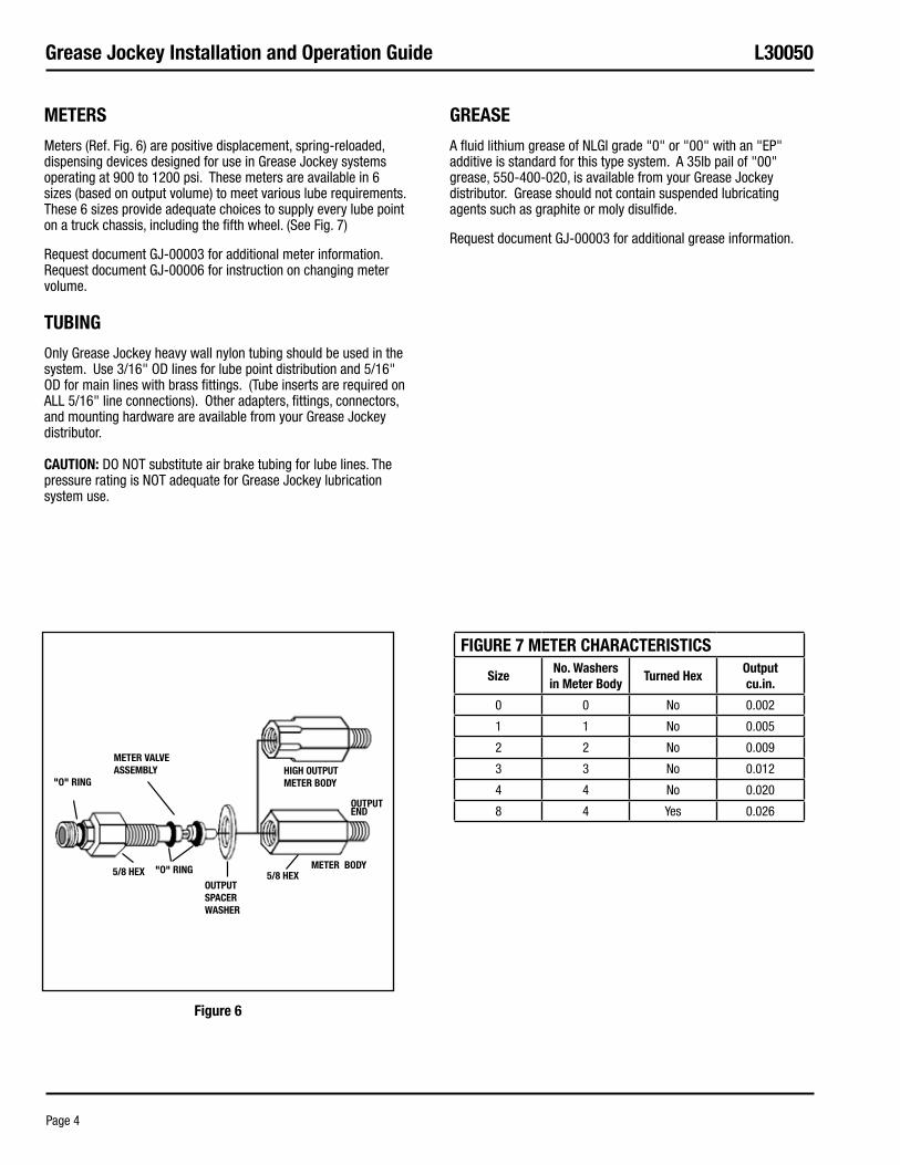
MeTers
Meters (Ref. Fig. 6) are positive displacement, spring-reloaded, dispensing devices designed for use in Grease Jockey systems operating at 900 to 1200 psi. These meters are available in 6 sizes (based on output volume) to meet various lube requirements. These 6 sizes provide adequate choices to supply every lube point on a truck chassis, including the fifth wheel. (See Fig. 7)
Request document GJ-00003 for additional meter information. Request document GJ-00006 for instruction on changing meter volume.
TuBING
Only Grease Jockey heavy wall nylon tubing should be used in the system. Use 3/16" OD lines for lube point distribution and 5/16" OD for main lines with brass fittings. (Tube inserts are required on ALL 5/16" line connections). Other adapters, fittings, connectors, and mounting hardware are available from your Grease Jockey distributor. CauTION: DO NOT substitute air brake tubing for lube lines. The pressure rating is NOT adequate for Grease Jockey lubrication system use.
Grease
A fluid lithium grease of NLGI grade "0" or "00" with an "EP" additive is standard for this type system. A 35lb pail of "00" grease, 550-400-020, is available from your Grease Jockey distributor. Grease should not contain suspended lubricating agents such as graphite or moly disulfide.
Request document GJ-00003 for additional grease information.
HIGH OuTPuT MeTer BODy
OuTPuT eND
MeTer VaLVe asseMBLy
5/8 HeXOuTPuT sPaCer WasHer
5/8 HeX
"O" rING
MeTer BODy"O" rING
Figure 6
FIGure 7 MeTer CHaraCTerIsTICs
sizeNo. Washers
in Meter BodyTurned Hex
Outputcu.in.
0 0 No 0.002
1 1 No 0.005
2 2 No 0.009
3 3 No 0.012
4 4 No 0.020
8 4 Yes 0.026
Grease Jockey Installation and Operation Guide L30050
Page 5
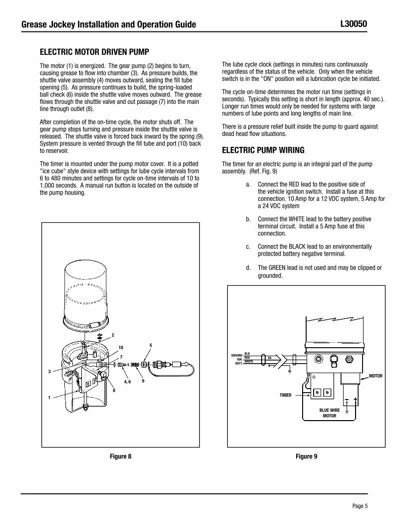
eLeCTrIC MOTOr DrIVeN PuMP
The motor (1) is energized. The gear pump (2) begins to turn, causing grease to flow into chamber (3). As pressure builds, the shuttle valve assembly (4) moves outward, sealing the fill tube opening (5). As pressure continues to build, the spring-loaded ball check (6) inside the shuttle valve moves outward. The grease flows through the shuttle valve and out passage (7) into the main line through outlet (8).
After completion of the on-time cycle, the motor shuts off. The gear pump stops turning and pressure inside the shuttle valve is released. The shuttle valve is forced back inward by the spring (9). System pressure is vented through the fill tube and port (10) back to reservoir.
The timer is mounted under the pump motor cover. It is a potted "ice cube" style device with settings for lube cycle intervals from 6 to 480 minutes and settings for cycle on-time intervals of 10 to 1,000 seconds. A manual run button is located on the outside of the pump housing.
The lube cycle clock (settings in minutes) runs continuously regardless of the status of the vehicle. Only when the vehicle switch is in the "ON" position will a lubrication cycle be initiated.
The cycle on-time determines the motor run time (settings in seconds). Typically this setting is short in length (approx. 40 sec.). Longer run times would only be needed for systems with large numbers of lube points and long lengths of main line.
There is a pressure relief built inside the pump to guard against dead head flow situations.
eLeCTrIC PuMP WIrING
The timer for an electric pump is an integral part of the pump assembly. (Ref. Fig. 9)
Connect the RED lead to the positive side of a. the vehicle ignition switch. Install a fuse at this connection. 10 Amp for a 12 VDC system, 5 Amp for a 24 VDC system
Connect the WHITE lead to the battery positive b. terminal circuit. Install a 5 Amp fuse at this connection.
Connect the BLACK lead to an environmentally c. protected battery negative terminal.
The GREEN lead is not used and may be clipped or d. grounded.
4, 6 9
5
7
10
2
1
3
8
reDBLk
WHITe
GrOuND IGN.
BaTT.
5a
TIMer
MOTOr
BLue WIre MOTOr
Figure 8 Figure 9
Grease Jockey Installation and Operation Guide L30050
Page 6
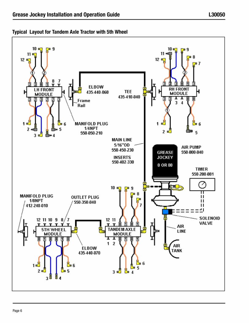
Typical Layout for Tandem axle Tractor with 5th Wheel
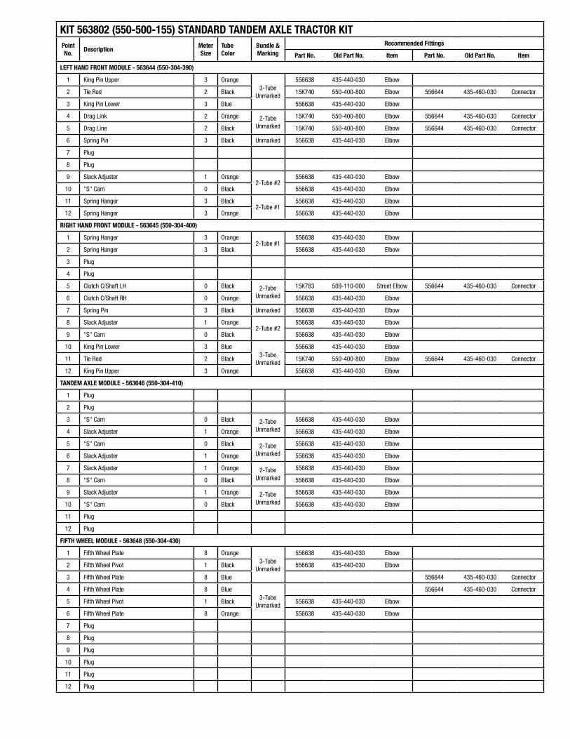
kIT 563802 (550-500-155) sTaNDarD TaNDeM aXLe TraCTOr kITPoint No.
DescriptionMeter size
Tube Color
Bundle & Marking
recommended Fittings
Part No. Old Part No. Item Part No. Old Part No. Item
LeFT HaND FrONT MODuLe - 563644 (550-304-390)
1 King Pin Upper 3 Orange3-Tube
Unmarked
556638 435-440-030 Elbow
2 Tie Rod 2 Black 15K740 550-400-800 Elbow 556644 435-460-030 Connector
3 King Pin Lower 3 Blue 556638 435-440-030 Elbow
4 Drag Link 2 Orange 2-Tube Unmarked
15K740 550-400-800 Elbow 556644 435-460-030 Connector
5 Drag Line 2 Black 15K740 550-400-800 Elbow 556644 435-460-030 Connector
6 Spring Pin 3 Black Unmarked 556638 435-440-030 Elbow
7 Plug
8 Plug
9 Slack Adjuster 1 Orange2-Tube #2
556638 435-440-030 Elbow
10 "S" Cam 0 Black 556638 435-440-030 Elbow
11 Spring Hanger 3 Black2-Tube #1
556638 435-440-030 Elbow
12 Spring Hanger 3 Orange 556638 435-440-030 Elbow
rIGHT HaND FrONT MODuLe - 563645 (550-304-400)
1 Spring Hanger 3 Orange2-Tube #1
556638 435-440-030 Elbow
2 Spring Hanger 3 Black 556638 435-440-030 Elbow
3 Plug
4 Plug
5 Clutch C/Shaft LH 0 Black 2-Tube Unmarked
15K783 509-110-000 Street Elbow 556644 435-460-030 Connector
6 Clutch C/Shaft RH 0 Orange 556638 435-440-030 Elbow
7 Spring Pin 3 Black Unmarked 556638 435-440-030 Elbow
8 Slack Adjuster 1 Orange2-Tube #2
556638 435-440-030 Elbow
9 "S" Cam 0 Black 556638 435-440-030 Elbow
10 King Pin Lower 3 Blue3-Tube
Unmarked
556638 435-440-030 Elbow
11 Tie Rod 2 Black 15K740 550-400-800 Elbow 556644 435-460-030 Connector
12 King Pin Upper 3 Orange 556638 435-440-030 Elbow
TaNDeM aXLe MODuLe - 563646 (550-304-410)
1 Plug
2 Plug
3 "S" Cam 0 Black 2-Tube Unmarked
556638 435-440-030 Elbow
4 Slack Adjuster 1 Orange 556638 435-440-030 Elbow
5 "S" Cam 0 Black 2-Tube Unmarked
556638 435-440-030 Elbow
6 Slack Adjuster 1 Orange 556638 435-440-030 Elbow
7 Slack Adjuster 1 Orange 2-Tube Unmarked
556638 435-440-030 Elbow
8 "S" Cam 0 Black 556638 435-440-030 Elbow
9 Slack Adjuster 1 Orange 2-Tube Unmarked
556638 435-440-030 Elbow
10 "S" Cam 0 Black 556638 435-440-030 Elbow
11 Plug
12 Plug
FIFTH WHeeL MODuLe - 563648 (550-304-430)
1 Fifth Wheel Plate 8 Orange3-Tube
Unmarked
556638 435-440-030 Elbow
2 Fifth Wheel Pivot 1 Black 556638 435-440-030 Elbow
3 Fifth Wheel Plate 8 Blue 556644 435-460-030 Connector
4 Fifth Wheel Plate 8 Blue3-Tube
Unmarked
556644 435-460-030 Connector
5 Fifth Wheel Pivot 1 Black 556638 435-440-030 Elbow
6 Fifth Wheel Plate 8 Orange 556638 435-440-030 Elbow
7 Plug
8 Plug
9 Plug
10 Plug
11 Plug
12 Plug
Grease Jockey Installation and Operation Guide L30050
Page 8
INsTaLLaTION sTePs
All lube points should be properly filled with grease before removal of zerk fittings to change to tube connector fittings. This ensures each lube point will readily accept grease.
step 1- PuMP
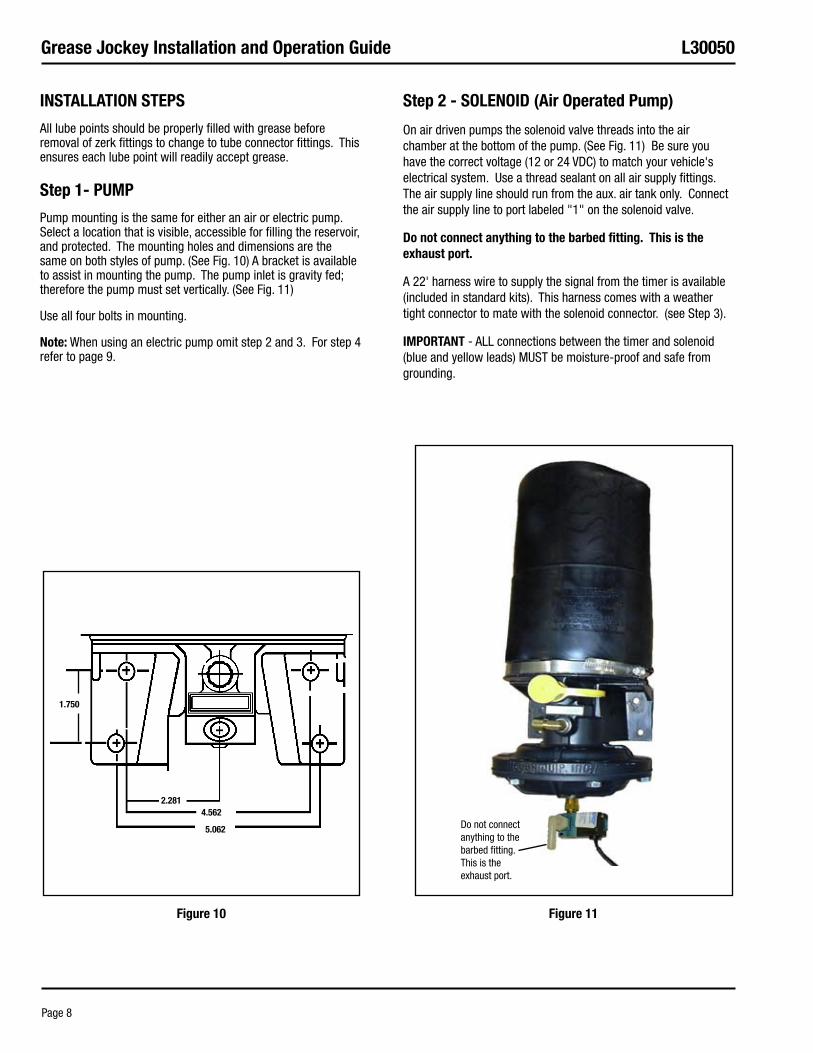
Pump mounting is the same for either an air or electric pump. Select a location that is visible, accessible for filling the reservoir, and protected. The mounting holes and dimensions are the same on both styles of pump. (See Fig. 10) A bracket is available to assist in mounting the pump. The pump inlet is gravity fed; therefore the pump must set vertically. (See Fig. 11)
Use all four bolts in mounting.
Note: When using an electric pump omit step 2 and 3. For step 4 refer to page 9.
step 2 - sOLeNOID (air Operated Pump)
On air driven pumps the solenoid valve threads into the air chamber at the bottom of the pump. (See Fig. 11) Be sure you have the correct voltage (12 or 24 VDC) to match your vehicle's electrical system. Use a thread sealant on all air supply fittings. The air supply line should run from the aux. air tank only. Connect the air supply line to port labeled "1" on the solenoid valve.
Do not connect anything to the barbed fitting. This is the exhaust port.
A 22' harness wire to supply the signal from the timer is available (included in standard kits). This harness comes with a weather tight connector to mate with the solenoid connector. (see Step 3).
IMPOrTaNT - ALL connections between the timer and solenoid (blue and yellow leads) MUST be moisture-proof and safe from grounding.
1.750
2.2814.562
5.062 Do not connect anything to the barbed fitting. This is the exhaust port.
Figure 10 Figure 11
Grease Jockey Installation and Operation Guide L30050
Page 9
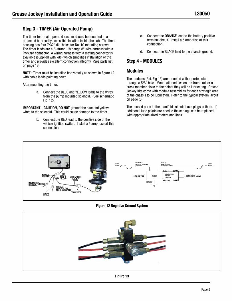
step 3 - TIMer (air Operated Pump)
The timer for an air operated system should be mounted in a protected but readily accessible location inside the cab. The timer housing has four 7/32" dia. holes for No. 10 mounting screws. The timer leads are a 5-strand, 18 gauge 8" wire harness with a Packard connector. A wiring harness with a mating connector is available (supplied with kits) which simplifies installation of the timer and provides excellent connection integrity. (See parts list on page 18).
NOTe: Timer must be installed horizontally as shown in figure 12 with cable leads pointing down.
After mounting the timer;
Connect the BLUE and YELLOW leads to the wires a. from the pump mounted solenoid. (See schematic Fig. 12).
IMPOrTaNT - CauTION, DO NOT ground the blue and yellow wires to the solenoid. This could cause damage to the timer.
Connect the RED lead to the positive side of the b. vehicle ignition switch. Install a 5 amp fuse at this connection.
Connect the ORANGE lead to the battery positive c. terminal circuit. Install a 5 amp fuse at this connection.
Connect the BLACK lead to the chassis ground.d.
step 4 - MODuLes
Modules
The modules (Ref. Fig 13) are mounted with a ported stud through a 5/8" hole. Mount all modules on the frame rail or a cross member close to the points they will be lubricating. Grease Jockey kits come with module assemblies for each strategic area of the chassis to be lubricated. Refer to the typical system layout on page (6).
The unused ports in the manifolds should have plugs in them. If additional lube points are needed these plugs can be replaced with appropriate sized meters and lines.
BLue BLaCk
yeLLOW WHITe
VaLVe
CONNeCTOr5-aMP Fuses
BLaCk (-) GrOuND
reD (+) (IGNITION ON) FrOM keysWITCH
LOaD WIres BLue &yeLLOW
LOaD WIres BLaCk & WHITe
OraNGe (+) BaTTery TerMINaL (MeMOry)
Figure 12 Negative Ground system
Figure 13
Grease Jockey Installation and Operation Guide L30050
Page 10
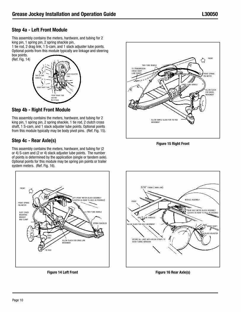
step 4a - Left Front Module
This assembly contains the meters, hardware, and tubing for 2 king pin, 1 spring pin, 2 spring shackle pin, 1 tie rod, 2 drag link, 1 S-cam, and 1 slack adjuster lube points. Optional points from this module typically are linkage and steering box points. (Ref. Fig. 14)
step 4b - right Front Module
This assembly contains the meters, hardware, and tubing for 2 king pin, 1 spring pin, 2 spring shackle, 1 tie rod, 2 clutch cross shaft, 1 S-cam, and 1 slack adjuster lube points. Optional points from this module typically may be body pivot pins. (Ref. Fig. 15).
step 4c - rear axle(s)
This assembly contains the meters, hardware, and tubing for (2 or 4) S-cam and (2 or 4) slack adjuster lube points. The number of points is determined by the application (single or tandem axle). Optional points for this module may be spring pin points or trailer system meters. (Ref. Fig. 16).
brake shaft tube
two 2-tube bundles
front brake tube routing & fittings
slack adjuster tube
left front meter block assembly (located as near to axle as possible)
two-tube bundle
spring shackles
allow slack for drag link movement
tie rod
dust cover mounting bracket and clamp
front spring pin meter
front
drag link
5/16" tubing ( main line)
module assemblyfront
two 2-tube bundles
allow slack for axle movement
secure all lines with nylon straps to avoid tubing abrasion
slack adjuster
brake shaft
rear axle meter block assembly (locate as near to axle as possible
to transmission cross shaft lube points
two-tube bundle
front spring pin meter
front
allow ample slack for tie rod movement
three-tube bundle
allow slack for wheel movement
Figure 14 Left Front Figure 16 rear axle(s)
Figure 15 right Front
Grease Jockey Installation and Operation Guide L30050
Page 11
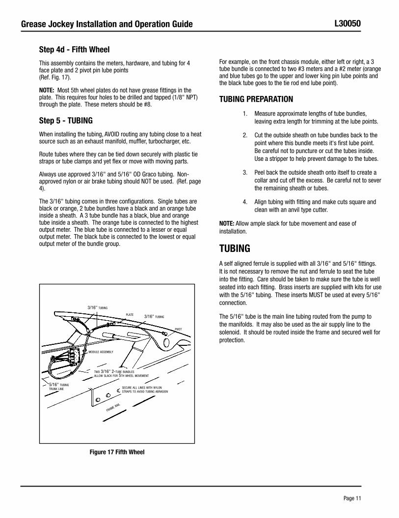
step 4d - Fifth Wheel
This assembly contains the meters, hardware, and tubing for 4 face plate and 2 pivot pin lube points (Ref. Fig. 17).
NOTe: Most 5th wheel plates do not have grease fittings in the plate. This requires four holes to be drilled and tapped (1/8" NPT) through the plate. These meters should be #8.
step 5 - TuBING
When installing the tubing, AVOID routing any tubing close to a heat source such as an exhaust manifold, muffler, turbocharger, etc.
Route tubes where they can be tied down securely with plastic tie straps or tube clamps and yet flex or move with moving parts.
Always use approved 3/16" and 5/16" OD Graco tubing. Non-approved nylon or air brake tubing should NOT be used. (Ref. page 4).
The 3/16" tubing comes in three configurations. Single tubes are black or orange, 2 tube bundles have a black and an orange tube inside a sheath. A 3 tube bundle has a black, blue and orange tube inside a sheath. The orange tube is connected to the highest output meter. The blue tube is connected to a lesser or equal output meter. The black tube is connected to the lowest or equal output meter of the bundle group.
For example, on the front chassis module, either left or right, a 3 tube bundle is connected to two #3 meters and a #2 meter (orange and blue tubes go to the upper and lower king pin lube points and the black tube goes to the tie rod end lube point).
TuBING PreParaTION
Measure approximate lengths of tube bundles, 1. leaving extra length for trimming at the lube points.
Cut the outside sheath on tube bundles back to the 2. point where this bundle meets it's first lube point. Be careful not to puncture or cut the tubes inside. Use a stripper to help prevent damage to the tubes.
Peel back the outside sheath onto itself to create a 3. collar and cut off the excess. Be careful not to sever the remaining sheath or tubes.
Align tubing with fitting and make cuts square and 4. clean with an anvil type cutter.
NOTe: Allow ample slack for tube movement and ease of installation.
TuBINGA self aligned ferrule is supplied with all 3/16" and 5/16" fittings. It is not necessary to remove the nut and ferrule to seat the tube into the fitting. Care should be taken to make sure the tube is well seated into each fitting. Brass inserts are supplied with kits for use with the 5/16" tubing. These inserts MUST be used at every 5/16" connection.
The 5/16" tube is the main line tubing routed from the pump to the manifolds. It may also be used as the air supply line to the solenoid. It should be routed inside the frame and secured well for protection.
3/16" tubing
plate 3/16" tubing
pivot
module assembly
secure all lines with nylon straps to avoid tubing abrasion
frame rail
two 3/16" 2-tube bundles allow slack for 5th wheel movement
5/16" tubing trunk line
Figure 17 Fifth Wheel
Grease Jockey Installation and Operation Guide L30050
Page 12
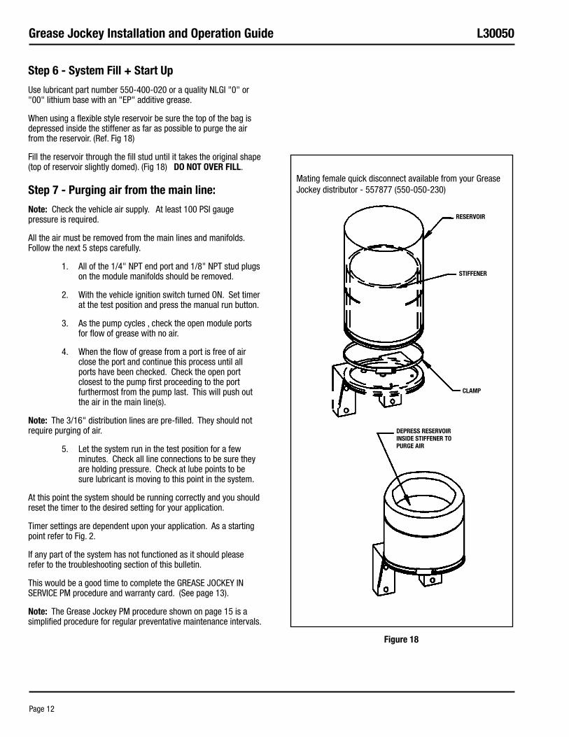
step 6 - system Fill + start up
Use lubricant part number 550-400-020 or a quality NLGI "0" or "00" lithium base with an "EP" additive grease.
When using a flexible style reservoir be sure the top of the bag is depressed inside the stiffener as far as possible to purge the air from the reservoir. (Ref. Fig 18)
Fill the reservoir through the fill stud until it takes the original shape (top of reservoir slightly domed). (Fig 18) DO NOT OVer FILL.
step 7 - Purging air from the main line:
Note: Check the vehicle air supply. At least 100 PSI gauge pressure is required.
All the air must be removed from the main lines and manifolds. Follow the next 5 steps carefully.
All of the 1/4" NPT end port and 1/8" NPT stud plugs 1. on the module manifolds should be removed.
With the vehicle ignition switch turned ON. Set timer 2. at the test position and press the manual run button.
As the pump cycles , check the open module ports 3. for flow of grease with no air.
When the flow of grease from a port is free of air 4. close the port and continue this process until all ports have been checked. Check the open port closest to the pump first proceeding to the port furthermost from the pump last. This will push out the air in the main line(s).
Note: The 3/16" distribution lines are pre-filled. They should not require purging of air.
Let the system run in the test position for a few 5. minutes. Check all line connections to be sure they are holding pressure. Check at lube points to be sure lubricant is moving to this point in the system.
At this point the system should be running correctly and you should reset the timer to the desired setting for your application.
Timer settings are dependent upon your application. As a starting point refer to Fig. 2.
If any part of the system has not functioned as it should please refer to the troubleshooting section of this bulletin.
This would be a good time to complete the GREASE JOCKEY IN SERVICE PM procedure and warranty card. (See page 13).
Note: The Grease Jockey PM procedure shown on page 15 is a simplified procedure for regular preventative maintenance intervals.
reserVOIr
sTIFFeNer
CLaMP
DePress reserVOIr INsIDe sTIFFeNer TO PurGe aIr
Mating female quick disconnect available from your Grease Jockey distributor - 557877 (550-050-230)
Figure 18
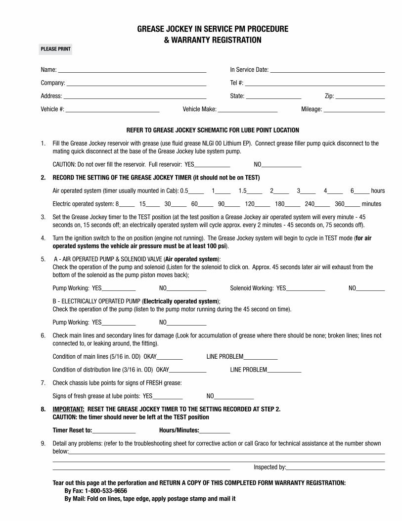
Grease JOCkey IN serVICe PM PrOCeDure & WarraNTy reGIsTraTION
PLease PrINT
Name: In Service Date:
Company: Tel #:
Address: State: Zip:
Vehicle #: Vehicle Make: Mileage:
reFer TO Grease JOCkey sCHeMaTIC FOr LuBe POINT LOCaTION
Fill the Grease Jockey reservoir with grease (use fluid grease NLGI 00 Lithium EP). Connect grease filler pump quick disconnect to the 1. mating quick disconnect at the base of the Grease Jockey lube system pump.
CAUTION: Do not over fill the reservoir. Full reservoir: YES NO
reCOrD THe seTTING OF THe Grease JOCkey TIMer 2. (it should not be on TesT)
Air operated system (timer usually mounted in Cab): 0.5 1 1.5 2 3 4 6 hours
Electric operated system: 8 15 30 60 90 120 180 240 360 minutes
Set the Grease Jockey timer to the TEST position (at the test position a Grease Jockey air operated system will every minute - 45 3. seconds on, 15 seconds off; an electrically operated system will cycle approx. every 2 minutes - 45 seconds on, 75 seconds off).
Tur4. n the ignition switch to the on position (engine not running). The Grease Jockey system will begin to cycle in TEST mode (for air operated systems the vehicle air pressure must be at least 100 psi).
A - AIR OPERATED PUMP & SOLENOID VALVE (5. air operated system):Check the operation of the pump and solenoid (Listen for the solenoid to click on. Approx. 45 seconds later air will exhaust from the bottom of the solenoid as the pump piston moves back);
Pump Working: YES NO Solenoid Working: YES NO
B - ELECTRICALLY OPERATED PUMP (electrically operated system);Check the operation of the pump (listen to the pump motor running during the 45 second on time).
Pump Working: YES NO
Check main lines and secondary lines for damage (Look for accumulation of grease where there should be none; broken lines; lines not 6. connected to, or leaking around, the fitting).
Condition of main lines (5/16 in. OD) OKAY LINE PROBLEM
Condition of distribution line (3/16 in. OD) OKAY LINE PROBLEM
Check chassis lube points for signs of FRESH grease:7.
Signs of fresh grease at lube points: YES NO
IMPOrTaNT:8. reseT THe Grease JOCkey TIMer TO THe seTTING reCOrDeD aT sTeP 2.CauTION: the timer should never be left at the TesT position
Timer reset to: Hours/Minutes:
Detail any problems: (refer to the troubleshooting sheet for corrective action or call Graco for technical assistance at the number shown 9. below: Inspected by:
Tear out this page at the perforation and reTurN a COPy OF THIs COMPLeTeD FOrM WarraNTy reGIsTraTION:By Fax: 1-800-533-9656By Mail: Fold on lines, tape edge, apply postage stamp and mail it
Attn: Customer ServiceGRACO, INC1201 Lund BlvdAnoka, MN 55303
PLACE FIRST CLASS
POSTAGE HERE
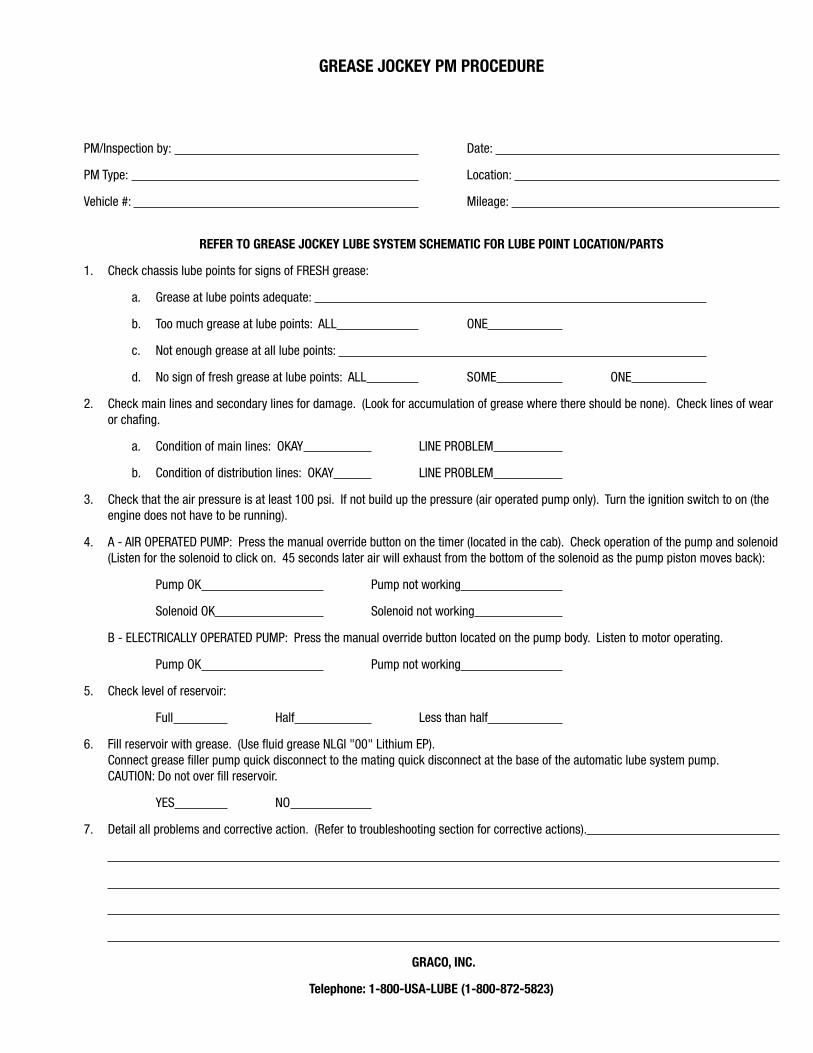
Grease JOCkey PM PrOCeDure
PM/Inspection by: Date:
PM Type: Location:
Vehicle #: Mileage:
reFer TO Grease JOCkey LuBe sysTeM sCHeMaTIC FOr LuBe POINT LOCaTION/ParTs
Check chassis lube points for signs of FRESH grease:1.
Grease at lube points adequate: a.
Too much grease at lube points: ALLb. ONE
Not enough grease at all lube points: c.
No sign of fresh grease at lube points: ALLd. SOME ONE
Check main lines and secondary lines for damage. (Look for accumulation of grease where there should be none). Check lines of wear 2. or chafing.
Condition of main lines: OKAYa. LINE PROBLEM
Condition of distribution lines: OKAYb. LINE PROBLEM
Check that the air pressure is at least 100 psi. If not build up the pressure (air operated pump only). Turn the ignition switch to on (the 3. engine does not have to be running).
A - 4. AIR OPERATED PUMP: Press the manual override button on the timer (located in the cab). Check operation of the pump and solenoid (Listen for the solenoid to click on. 45 seconds later air will exhaust from the bottom of the solenoid as the pump piston moves back):
Pump OK Pump not working
Solenoid OK Solenoid not working
B - ELECTRICALLY OPERATED PUMP: Press the manual override button located on the pump body. Listen to motor operating.
Pump OK Pump not working
Check level of reservoir:5.
Full Half Less than half
Fill reservoir with grease. (Use fluid grease NLGI "00" Lithium EP).6. Connect grease filler pump quick disconnect to the mating quick disconnect at the base of the automatic lube system pump. CAUTION: Do not over fill reservoir.
YES NO
Detail all problems and corrective action. (Refer to troubleshooting section for corrective actions).7.
GraCO, INC.
Telephone: 1-800-usa-LuBe (1-800-872-5823)
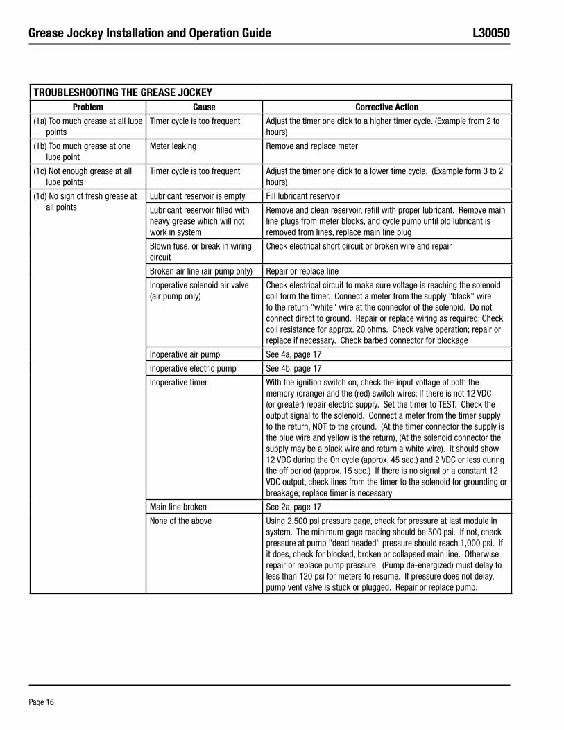
Grease Jockey Installation and Operation Guide L30050
Page 16
TrOuBLesHOOTING THe Grease JOCkeyProblem Cause Corrective action
(1a) Too much grease at all lube points
Timer cycle is too frequent Adjust the timer one click to a higher timer cycle. (Example from 2 to hours)
(1b) Too much grease at one lube point
Meter leaking Remove and replace meter
(1c) Not enough grease at all lube points
Timer cycle is too frequent Adjust the timer one click to a lower time cycle. (Example form 3 to 2 hours)
(1d) No sign of fresh grease at all points
Lubricant reservoir is empty Fill lubricant reservoir
Lubricant reservoir filled with heavy grease which will not work in system
Remove and clean reservoir, refill with proper lubricant. Remove main line plugs from meter blocks, and cycle pump until old lubricant is removed from lines, replace main line plug
Blown fuse, or break in wiring circuit
Check electrical short circuit or broken wire and repair
Broken air line (air pump only) Repair or replace line
Inoperative solenoid air valve (air pump only)
Check electrical circuit to make sure voltage is reaching the solenoid coil form the timer. Connect a meter from the supply "black" wire to the return "white" wire at the connector of the solenoid. Do not connect direct to ground. Repair or replace wiring as required: Check coil resistance for approx. 20 ohms. Check valve operation; repair or replace if necessary. Check barbed connector for blockage
Inoperative air pump See 4a, page 17
Inoperative electric pump See 4b, page 17
Inoperative timer With the ignition switch on, check the input voltage of both the memory (orange) and the (red) switch wires: If there is not 12 VDC (or greater) repair electric supply. Set the timer to TEST. Check the output signal to the solenoid. Connect a meter from the timer supply to the return, NOT to the ground. (At the timer connector the supply is the blue wire and yellow is the return), (At the solenoid connector the supply may be a black wire and return a white wire). It should show 12 VDC during the On cycle (approx. 45 sec.) and 2 VDC or less during the off period (approx. 15 sec.) If there is no signal or a constant 12 VDC output, check lines from the timer to the solenoid for grounding or breakage; replace timer is necessary
Main line broken See 2a, page 17
None of the above Using 2,500 psi pressure gage, check for pressure at last module in system. The minimum gage reading should be 500 psi. If not, check pressure at pump "dead headed" pressure should reach 1,000 psi. If it does, check for blocked, broken or collapsed main line. Otherwise repair or replace pump pressure. (Pump de-energized) must delay to less than 120 psi for meters to resume. If pressure does not delay, pump vent valve is stuck or plugged. Repair or replace pump.
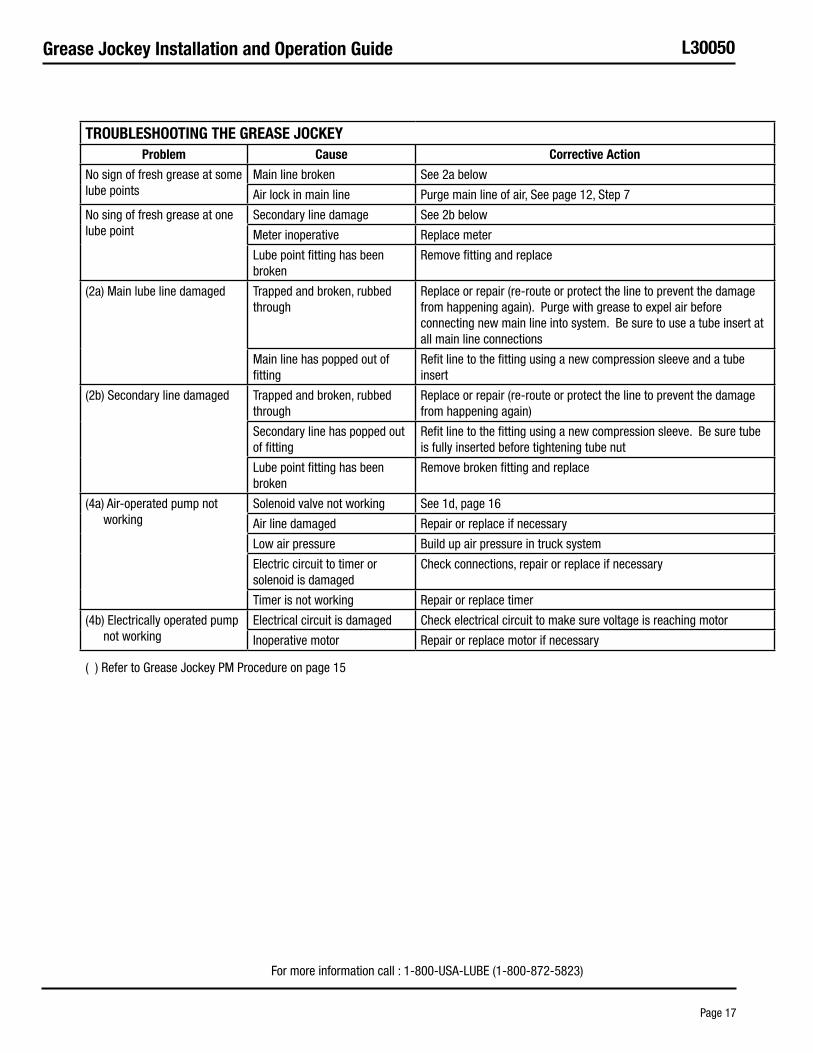
Grease Jockey Installation and Operation Guide L30050
Page 17
TrOuBLesHOOTING THe Grease JOCkeyProblem Cause Corrective action
No sign of fresh grease at some lube points
Main line broken See 2a below
Air lock in main line Purge main line of air, See page 12, Step 7
No sing of fresh grease at one lube point
Secondary line damage See 2b below
Meter inoperative Replace meter
Lube point fitting has been broken
Remove fitting and replace
(2a) Main lube line damaged Trapped and broken, rubbed through
Replace or repair (re-route or protect the line to prevent the damage from happening again). Purge with grease to expel air before connecting new main line into system. Be sure to use a tube insert at all main line connections
Main line has popped out of fitting
Refit line to the fitting using a new compression sleeve and a tube insert
(2b) Secondary line damaged Trapped and broken, rubbed through
Replace or repair (re-route or protect the line to prevent the damage from happening again)
Secondary line has popped out of fitting
Refit line to the fitting using a new compression sleeve. Be sure tube is fully inserted before tightening tube nut
Lube point fitting has been broken
Remove broken fitting and replace
(4a) Air-operated pump not working
Solenoid valve not working See 1d, page 16
Air line damaged Repair or replace if necessary
Low air pressure Build up air pressure in truck system
Electric circuit to timer or solenoid is damaged
Check connections, repair or replace if necessary
Timer is not working Repair or replace timer
(4b) Electrically operated pump not working
Electrical circuit is damaged Check electrical circuit to make sure voltage is reaching motor
Inoperative motor Repair or replace motor if necessary
( ) Refer to Grease Jockey PM Procedure on page 15
For more information call : 1-800-USA-LUBE (1-800-872-5823)
Grease Jockey Installation and Operation Guide L30050
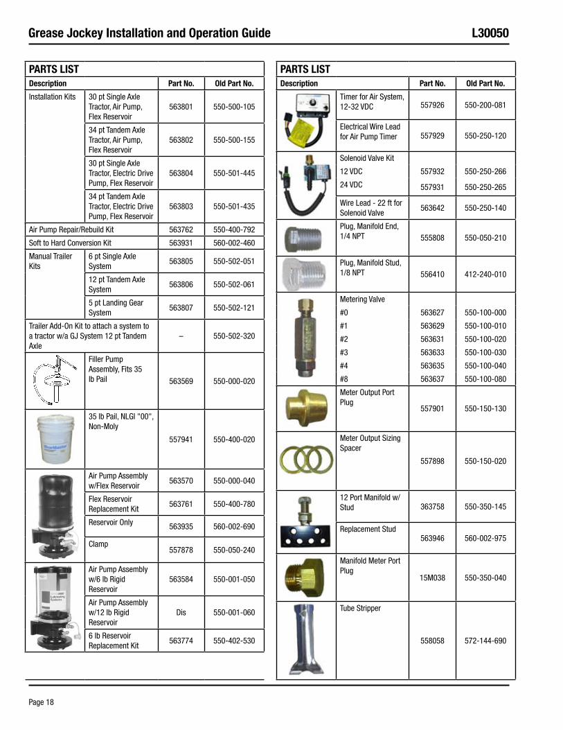
Page 18
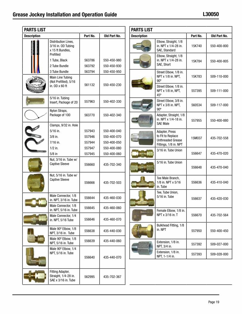
ParTs LIsTDescription Part No. Old Part No.
Installation Kits 30 pt Single Axle Tractor, Air Pump, Flex Reservoir
563801 550-500-105
34 pt Tandem Axle Tractor, Air Pump, Flex Reservoir
563802 550-500-155
30 pt Single Axle Tractor, Electric Drive Pump, Flex Reservoir
563804 550-501-445
34 pt Tandem Axle Tractor, Electric Drive Pump, Flex Reservoir
563803 550-501-435
Air Pump Repair/Rebuild Kit 563762 550-400-792
Soft to Hard Conversion Kit 563931 560-002-460
Manual Trailer Kits
6 pt Single Axle System
563805 550-502-051
12 pt Tandem Axle System
563806 550-502-061
5 pt Landing Gear System
563807 550-502-121
Trailer Add-On Kit to attach a system to a tractor w/a GJ System 12 pt Tandem Axle
– 550-502-320
Filler Pump Assembly, Fits 35 lb Pail 563569 550-000-020
35 lb Pail, NLGI "00", Non-Moly
557941 550-400-020
Air Pump Assembly w/Flex Reservoir
563570 550-000-040
Flex Reservoir Replacement Kit
563761 550-400-780
Reservoir Only 563935 560-002-690
Clamp557878 550-050-240
Air Pump Assembly w/6 lb Rigid Reservoir
563584 550-001-050
Air Pump Assembly w/12 lb Rigid Reservoir
Dis 550-001-060
6 lb Reservoir Replacement Kit
563774 550-402-530
ParTs LIsTDescription Part No. Old Part No.
Timer for Air System, 12-32 VDC 557926 550-200-081
Electrical Wire Lead for Air Pump Timer 557929 550-250-120
Solenoid Valve Kit
12 VDC 557932 550-250-266
24 VDC 557931 550-250-265
Wire Lead - 22 ft for Solenoid Valve
563642 550-250-140
Plug, Manifold End, 1/4 NPT 555808 550-050-210
Plug, Manifold Stud, 1/8 NPT 556410 412-240-010
Metering Valve
#0 563627 550-100-000
#1 563629 550-100-010
#2 563631 550-100-020
#3 563633 550-100-030
#4 563635 550-100-040
#8 563637 550-100-080
Meter Output Port Plug
557901 550-150-130
Meter Output Sizing Spacer
557898 550-150-020
12 Port Manifold w/Stud 363758 550-350-145
Replacement Stud563946 560-002-975
Manifold Meter Port Plug
15M038 550-350-040
Tube Stripper
558058 572-144-690
Grease Jockey Installation and Operation Guide L30050
Page 19
ParTs LIsTDescription Part No. Old Part No.
Distribution Lines, 3/16 in. OD Tubing x 15 ft Bundles, Prefilled
1 Tube, Black 563786 550-450-980
2 Tube Bundle 563792 550-450-930
3 Tube Bundle 563794 550-450-950
Main Line Tubing (Not Prefilled), 5/16 in. OD x 60 ft 561132 550-450-230
5/16 in. Tubing Insert, Package of 20 557963 550-402-330
Nylon Straps, Package of 100 563770 550-402-340
Clamps, 9/32 in. Hole
5/16 in. 557943 550-400-040
3/8 in. 557946 550-400-070
7/16 in. 557944 550-400-050
1/2 in. 557947 550-400-080
5/8 in 557945 550-400-060
Nut, 3/16 in. Tube w/Captive Sleeve 556660 435-702-340
Nut, 5/16 in. Tube w/Captive Sleeve
556666 435-702-503
Male Connector, 1/8 in. NPT, 3/16 in. Tube
556644 435-460-030
Male Connector, 1/8 in. NPT, 5/16 in. Tube
556645 435-460-060
Male Connector, 1/4 in. NPT, 5/16 Tube 556646 435-460-070
Male 90º Elbow, 1/8 NPT, 3/16 in. Tube
556638 435-440-030
Male 90º Elbow, 1/8 NPT, 5/16 in. Tube
556639 435-440-060
Male 90º Elbow, 1/4 NPT, 5/16 in. Tube
556640 435-440-070
Fitting Adapter, Straight, 1/4-28 in. SAE x 3/16 in. Tube
562995 435-702-367
ParTs LIsTDescription Part No. Old Part No.
Elbow, Straight, 1/8 in. NPT x 1/4-28 in. SAE, Standard
15K740 550-400-800
Elbow, Straight, 1/8 in. NPT x 1/4-28 in. SAE, Short
15K784 550-400-805
Street Elbow, 1/8 in. NPT x 1/8 in. NPT, 90º
15K783 509-110-000
Street Elbow, 1/8 in. NPT x 1/8 in, NPT, 45º
557395 509-111-000
Street Elbow, 3/8 in. NPT x 3/8 in. NPT, 90º
560534 509-117-000
Adapter, Straight, 1/8 in. NPT x 1/4-18 in. SAE Male
557955 550-400-880
Adapter, Press to Fit to Replace Unthreaded Grease Fittings, 1/8 in. NPT
15M037 435-702-558
3/16 in. Tube Union556647 435-470-020
5/16 in. Tube Union556648 435-470-040
Tee Male Branch, 1/8 in. NPT x 5/16 in. Tube
556636 435-410-040
Tee, Tube Union, 5/16 in. Tube 556637 435-420-030
Female Elbow, 1/8 in. NPT x 3/16 in. T 556670 435-702-564
Bulkhead Fitting, 1/8 in. NPT 557950 550-400-450
Extension, 1/8 in. NPT, 3/4 in.
557392 509-027-000
Extension, 1/8 in. NPT, 1-1/4 in.
557393 509-028-000
Grease Jockey Installation and Operation Guide L30050
Page 20
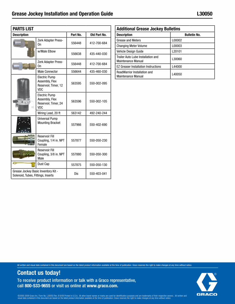
ParTs LIsTDescription Part No. Old Part No.
Zerk Adapter Press-On 556448 412-700-684
w/Male Elbow556638 435-440-030
Zerk Adapter Press-On
556448 412-700-684
Male Connector 556644 435-460-030
Electric Pump Assembly, Flex Reservoir, Timer, 12 VDC
563595 550-002-095
Electric Pump Assembly, Flex Reservoir, Timer, 24 VDC
563596 550-002-105
Wiring Lead, 20 ft 563142 492-240-244
Universal Pump Mounting Bracket 557966 550-402-690
Reservoir Fill Coupling, 1/4 in. NPT Female
557877 550-050-230
Reservoir Fill Coupling, 3/8 in. NPT Male
557880 550-050-300
Dust Cap 557875 550-050-130
Grease Jockey Basic Inventory Kit - Solenoid, Tubes, Fittings, Inserts Dis 550-403-041
additional Grease Jockey BulletinsDescription Bulletin No.
Grease and Meters L00002
Changing Meter Volume L00003
Vehicle Design Guide L20101
Trailer Auto Lube Installation and Maintenance Manual
L30060
EZ Greaser Installation Instructions L44000
RoadWarrior Installation and Maintenance Manual
L40050
All written and visual data contained in this document are based on the latest product information available at the time of publication. Graco reserves the right to make changes at any time without notice.
Contact us today!To receive product information or talk with a Graco representative, call 800-533-9655 or visit us online at www.graco.com.
©2006-2009 Graco Inc. Form No. L30050 Rev. B 6/09 Printed in U.S.A. All other brand names or marks are used for identification purposes and are trademarks of their respective owners. All written and visual data contained in this document are based on the latest product information available at the time of publication. Graco reserves the right to make changes at any time without notice.


![Guide To Grease Interceptors revised draft1[1]12208 · Guide To Grease Interceptors Eliminating the Mystery Design & Operation Standards PDI- G101 A112.14.3 A112.14.4 Sizing & Placement](https://img.pdfslide.us/doc/110x75/5c2bf8f609d3f2c47f8cb0e4/guide-to-grease-interceptors-revised-draft11-guide-to-grease-interceptors.jpg)