Embed Size (px)
Citation preview

L23: Electromagnetic compatibility
L23: 21-MAY-2019
Lund University / LTH / IEA / AR / EIEN25 / 2019-05-21 2
Outlook
• Electromagnetic energy– Emission and propagation
– Interference and disturbance
• Electromagnetic compatibility – Power electronics
– Electric drives
• Remedies and Regulations– Conducted emission limits
Lund University / LTH / IEA / AR / EIEN25 / 2019-05-21 3
Electromagnetic compatibility
• Electromagnetic compatibility (EMC) is the branch of electrical engineering concerned with the unintentional generation, propagation and reception of electromagnetic energy which may cause unwanted effects such as electromagnetic interference (EMI)
• EMC issues– Emission (generation) – reduce unwanted emission
– Coupling – identify propagation mechanisms between transmitter and receiver
– Susceptibility – (receiver as victim) lack of immunity to electromagnetic disturbances
Lund University / LTH / IEA / AR / EIEN25 / 2019-05-21 4
EMC is an equipment
characteristic or property
EMI is a phenomenon
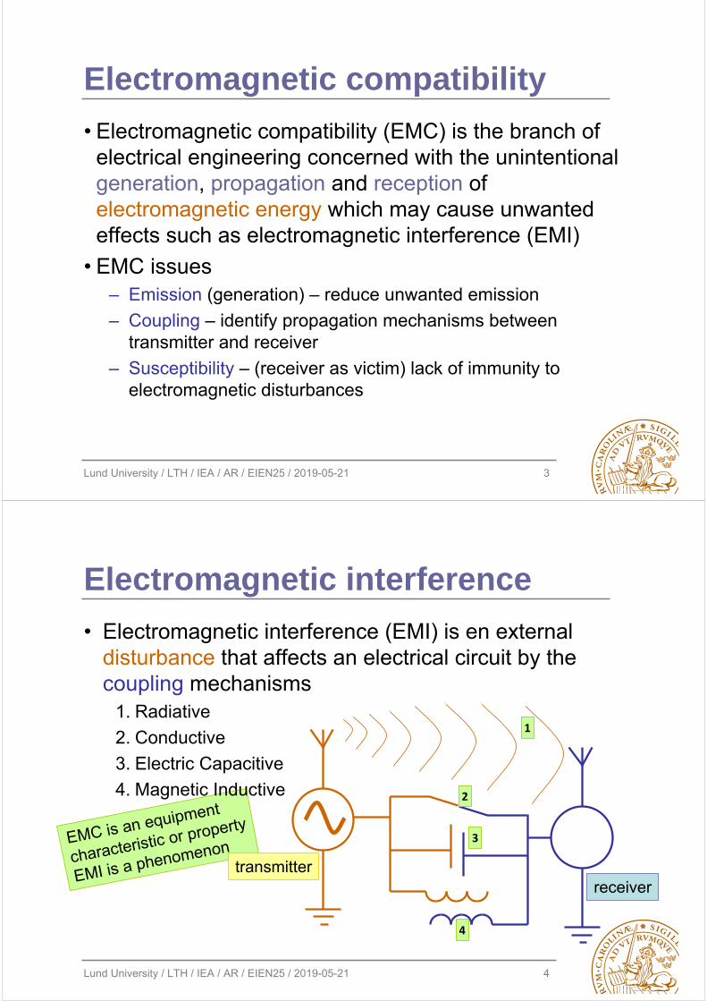
Electromagnetic interference
• Electromagnetic interference (EMI) is en external disturbance that affects an electrical circuit by the coupling mechanisms
1. Radiative
2. Conductive
3. Electric Capacitive
4. Magnetic Inductive
transmitterreceiver
1
2
3
4

Lund University / LTH / IEA / AR / EIEN25 / 2019-05-21 5
Conducted emission
• Electromagnetic energy propagation via a direct electric contact, capacitive and inductive paths in a power distribution network (cables, transmission line, frames, …)
ZdiffUdiffVcom
Vcom ZcomZcom
Idiff
Idiff
Icom
Icom
Coupled less than
a wavelength apart
compared to wave
propagation
Lund University / LTH / IEA / AR / EIEN25 / 2019-05-21 6
Types of interference
• Continuous wave from DC to daylight– Audio frequency from low to 20 kHz
– Radio frequency 20kHz to 30MHz for conducted EMI
– Broadband noise
• Pulse or transient interference– Switched & pulsed supplies (repetitive)
– Power line surges & pulses
– Electrostatic discharge, lightning
– Geomagnetically induced currents
Lund University / LTH / IEA / AR / EIEN25 / 2019-05-21 7
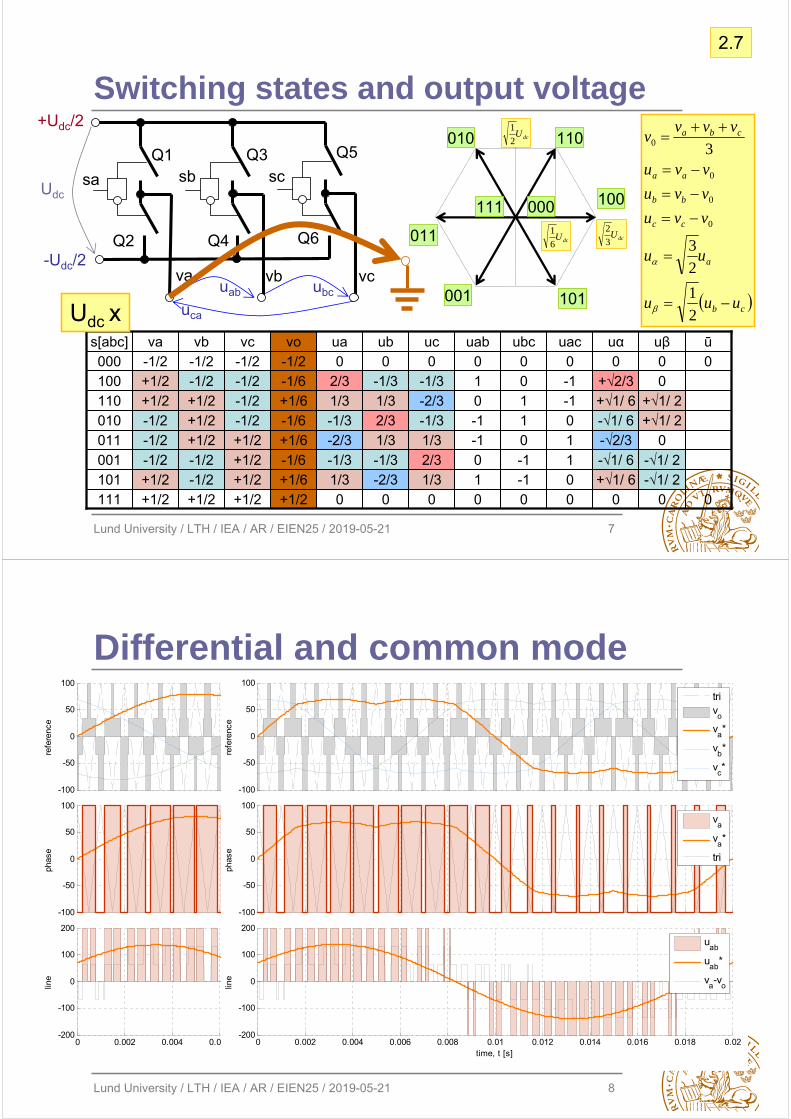
Switching states and output voltage
0
0ū
0-√1/ 2-√1/ 2
0+√1/ 2+√1/ 2
00
uβ
01/3-1/3
-2/3-1/31/32/30
ua
0+√1/ 6-√1/ 6
-√2/3-√1/ 6+√1/ 6+√2/3
0uα
010
-1-1010
uab
001
10-1-10
uac
0-1-1
01100
ubc
01/32/3
1/3-1/3-2/3-1/3
0uc
0-2/3-1/3
1/32/31/3-1/3
0ubvb vovc
+1/6+1/2-1/2+1/2101-1/6+1/2-1/2-1/2001
+1/6+1/2+1/2-1/2011-1/6-1/2+1/2-1/2010+1/6-1/2+1/2+1/2110
+1/2+1/2+1/2+1/2111
-1/6-1/2-1/2+1/2100-1/2-1/2-1/2-1/2000
vas[abc]
sa
Q1
+Udc/2
Udc
uabva
-Udc/2
sb scQ3 Q5
Q2 Q4 Q6
vb vcubc
uca
dcU3
2dcU
6
1
dcU2
1
100
011
110010
001 101
000111
cb
a
cc
bb
aa
cba
uuu
uu
vvu
vvu
vvu
vvvv
2
1
2
3
3
0
0
0
0
Udc x
2.7
Lund University / LTH / IEA / AR / EIEN25 / 2019-05-21 8
Differential and common mode
0 0.002 0.004 0.006 0.008 0.01 0.012 0.014 0.016 0.018 0.02-200
-100
0
100
200
line
time, t [s]
uab
uab
*
va-v
o
-100
-50
0
50
100
phas
e
va
va*
tri
-100
-50
0
50
100
refe
renc
e
triv
o
va*
vb*
vc*
0 0.002 0.004 0.006 0.008 0.01 0.012 0.014 0.016 0.018 0.02-200
-100
0
100
200
line
time, t [s]
uab
uab
*
va-v
o
-100
-50
0
50
100
phas
e
va
va*
tri
-100
-50
0
50
100
refe
renc
e
triv
o
va*
vb*
vc*

Lund University / LTH / IEA / AR / EIEN25 / 2019-05-21 9
Modulation spectra
• Modulation spectrum from low to high speed and back
– Fundamental carries out power amplification control action
– Common mode voltage excites capacitive insulation currents
– High frequency noise
Lund University / LTH / IEA / AR / EIEN25 / 2019-05-21 10
Fast switching inverters
• dV/dt – short voltage rise time from –Udc/2 to +Udc/2
• Wave propagation time can be in the same order of magnitude as voltage switch on
– Wave reflection due to impedance mismatch as μmachine>μcable
– Critical cable length that causes full voltage wave reflection
– Voltage overshoot at motor winding terminal – voltage can be doubled
– Nonlinear voltage distribution causes E-field stress and discharge
''cablecablecable
cable
cablep CLl
v
lt

Lund University / LTH / IEA / AR / EIEN25 / 2019-05-21 11
Trapezoidal waveform spectrum
• Time domain
• Frequency domain
T
d
tr
t
A
2A/(d/T)
1/πd
Log(f)
A
1/πtr
2A/(πTf)
2A/(π2Ttrf2)1/T
Lund University / LTH / IEA / AR / EIEN25 / 2019-05-21 12
Electric drive system
• HF effects in inverter-fed machines– PWM→HF emission, high dV/dt+Ucom vs reflection & overshoot
• Grounding current, shaft voltage, bearing currents– Unbalanced magnetic field, axial rotor flux, electrostatic effect, …
– HF bearing currents: non circulating discharge and circulating

Lund University / LTH / IEA / AR / EIEN25 / 2019-05-21 13
Insulation system response
• Electrical machine as a load– RC for electric insulation
system (EIS) & RL for windings
– Ringing at voltage switching– Voltage distribution
determined by distributed capacitances – local inception E field and discharges
• Leakage current measurement
– Ground, differential across winding, zero sequence, ..
–10
-110
010
110
210
310
410
5-0.05
0
0.05
0.1
0.15
0.2
0.25
0.3
0.35
0.4
indu
ctan
ce,
L [H
]
10-1
100
101
102
103
104
105
100
101
102
103
104
105
resi
stan
ce,
R [
Ohm
]
frequency, f [Hz]
HMOU12
HMRU12
HKRU12
HKRU-VW
FEO 1mA
FEO 1A
FER 1mA
FER 1A
A B C D
+
– +
+’
–
–’
RMF & LMF CMF1 CMF2
ZCM(f)
ZDM(f)f
Z(f)
fR1 fR2 fR3 fR4 fR5
Lund University / LTH / IEA / AR / EIEN25 / 2019-05-21 14
d=2μm E=4.9kV/mm
d=12μm E=3.8kV/mm
d=7μmE=4.3kV/mm
d=4μm E=4.6kV/mm
B:32
A:17 A:32
B:17
43
Electric field intensity E, [kV/mm]
1
Insulation fatigue and failure
• Variable speed drive insulation system safety requirements – electric field distribution over the imperfect insulation system at possible thermal load conditions
• Electrical stresses vsdurability & dielectric insulation capability testing
– polarization index, high potential, C, tan δ, surge characterization and partial discharge recognition
Lund University / LTH / IEA / AR / EIEN25 / 2019-05-21 15
Interference mitigation
• Electromagnetic compatibility by looking at – (quiet) sources of disturbances
– (inhibit) coupling paths
– (harden) potential victims (stresses, fatigue, failure)
• Mitigation techniques– Grounding and shielding – providing low impedance path for EMI
– Decoupling by introducing RF filters
– Transmission line techniques – differential signal and return path balancing, impedance matching
Lund University / LTH / IEA / AR / EIEN25 / 2019-05-21 16
Procedure to achieve EMC
• Customer specification and applicable standards– Emissions– Immunity
• Calculation of generation of harmonic currents, filter design and selection of modulation strategy
• Design rules to improve immunity and to minimize EMI and magnetic fields
• Immunity and emission testing on apparatus or system level in laboratory/test room
• Final validation of EMI, magnetic fields and harmonic currents by measurements on site

Lund University / LTH / IEA / AR / EIEN25 / 2019-05-21 17
Example
• LISN – line impedance stabilization network – LPF of known impedance and measurement point
Lund University / LTH / IEA / AR / EIEN25 / 2019-05-21 18
Measurements, parameter identification
DM @ 0.5MHz
• Frequency response analysis, frequencies and excitation modes ofinterest, circuit and parameter identification, sensitivity analysis, …