Embed Size (px)
Citation preview
L2 / L3 Switches
Link Aggregation
Configuration Guide
Revision 1.0
Link Aggregation Configuration Guide
Supermicro L2/L3 Switches Configuration Guide 2
The information in this USER’S MANUAL has been carefully reviewed and is believed to be accurate. The vendor
assumes no responsibility for any inaccuracies that may be contained in this document, makes no commitment to
update or to keep current the information in this manual, or to notify any person or organization of the updates.
Please Note: For the most up-to-date version of this manual, please see our web site at www.supermicro.com.
Super Micro Computer, Inc. (“Supermicro”) reserves the right to make changes to the product described in this
manual at any time and without notice. This product, including software, if any, and documentation may not, in
whole or in part, be copied, photocopied, reproduced, translated or reduced to any medium or machine without
prior written consent.
IN NO EVENT WILL SUPERMICRO BE LIABLE FOR DIRECT, INDIRECT, SPECIAL, INCIDENTAL, SPECULATIVE OR
CONSEQUENTIAL DAMAGES ARISING FROM THE USE OR INABILITY TO USE THIS PRODUCT OR DOCUMENTATION,
EVEN IF ADVISED OF THE POSSIBILITY OF SUCH DAMAGES. IN PARTICULAR, SUPERMICRO SHALL NOT HAVE
LIABILITY FOR ANY HARDWARE, SOFTWARE, OR DATA STORED OR USED WITH THE PRODUCT, INCLUDING THE
COSTS OF REPAIRING, REPLACING, INTEGRATING, INSTALLING OR RECOVERING SUCH HARDWARE, SOFTWARE, OR
DATA.
Any disputes arising between manufacturer and customer shall be governed by the laws of Santa Clara County in
the State of California, USA. The State of California, County of Santa Clara shall be the exclusive venue for the
resolution of any such disputes. Super Micro's total liability for all claims will not exceed the price paid for the
hardware product.
FCC Statement: This equipment has been tested and found to comply with the limits for a Class A digital device
pursuant to Part 15 of the FCC Rules. These limits are designed to provide reasonable protection against harmful
interference when the equipment is operated in a commercial environment. This equipment generates, uses, and
can radiate radio frequency energy and, if not installed and used in accordance with the manufacturer’s instruction
manual, may cause harmful interference with radio communications. Operation of this equipment in a residential
area is likely to cause harmful interference, in which case you will be required to correct the interference at your
own expense.
California Best Management Practices Regulations for Perchlorate Materials: This Perchlorate warning applies only
to products containing CR (Manganese Dioxide) Lithium coin cells. Perchlorate Material-special handling may
apply. See http://www.dtsc.ca.gov/hazardouswaste/perchlorate/ for further details.
Manual Revision 1.0
Release Date: January 25, 2013
Unless you request and receive written permission from Super Micro Computer, Inc., you may not copy any part of
this document.
Information in this document is subject to change without notice. Other products and companies referred to
herein are trademarks or registered trademarks of their respective companies or mark holders.
Copyright © 2013 by Super Micro Computer, Inc.
All rights reserved.
Printed in the United States of America
Link Aggregation Configuration Guide
Supermicro L2/L3 Switches Configuration Guide 3
Contents 1 Link Aggregation Configuration Guide .................................................................................................. 4
1.1 Link Aggregation Basics ................................................................................................................. 4
1.2 Link Aggregation Support .............................................................................................................. 5
1.3 Link Aggregation Numbers ............................................................................................................ 6
1.4 Link Aggregation Defaults ............................................................................................................. 6
1.5 Static Link Aggregation.................................................................................................................. 6
1.6 Dynamic Link Aggregation - LACP ................................................................................................. 6
1.7 Creating Port Channels ................................................................................................................. 8
1.7.1 Creating Port Channel Interfaces .......................................................................................... 8
1.7.2 Adding Member Ports to Port Channels ............................................................................... 9
1.8 Modifying Port Channels ............................................................................................................. 11
1.8.1 Modifying Port Channel Parameters ................................................................................... 11
1.8.2 Modifying Port Channel Member Ports .............................................................................. 11
1.9 Removing Port Channels ............................................................................................................. 14
1.10 LACP Parameters ......................................................................................................................... 15
1.10.1 LACP System Priority ........................................................................................................... 16
1.10.2 LACP Port Priority ................................................................................................................ 16
1.10.3 LACP Timeout ...................................................................................................................... 18
1.10.4 LACP Wait Time ................................................................................................................... 19
1.11 Load Balancing ............................................................................................................................ 20
1.12 Disabling Link Aggregation Feature ............................................................................................ 22
1.13 Link Aggregation Configuration Example .................................................................................... 23
Link Aggregation Configuration Guide
Supermicro L2/L3 Switches Configuration Guide 4
1 Link Aggregation Configuration Guide
This document describes the Link Aggregation feature supported in Supermicro Layer 2 / Layer 3 switch
products.
This document covers the Link Aggregation configurations for the below listed Supermicro switch
Products.
The majority of this document applies to the above listed Supermicro switch products. In any particular
sub section however, the contents might vary across these switch product models. In those sections the
differences are clearly identified with reference to particular switch product models. If any particular
switch product model is not referenced, the reader can safely assume that the content is applicable to
all the above listed models.
Throughout this document, the common term “switch” refers to any of the above listed
Supermicro switch product models unless a particular switch product model is noted.
1.1 Link Aggregation Basics The Link Aggregation feature when helps connecting two or more physical links between two network
devices without forming loops. Link Aggregation can be used between switches, servers and routers.
Link Aggregation provides the following advantages:
Top of Rack Switches
• SSE-G24-TG4
• SSE-G48-TG4
• SSE-X24S
• SSE-X3348S
• SSE-X3348T
Blade Switches
• SBM-GEM-X2C
• SBM-GEM-X2C+
• SBM-GEM-X3S+
• SBM-XEM-X10SM
Link Aggregation Configuration Guide
Supermicro L2/L3 Switches Configuration Guide 5
⇒ Increased bandwidth – User can connect up to eight physical links between devices to increase
the link bandwidth. When 1 Gbps links are aggregated, users can get an aggregated link with up
to 8 Gbps bandwidth . In 10Gig switches, user can aggregate eight 10Gig ports to get up to 80
Gbps speed aggregated uplink.
⇒ Incremental bandwidth – Users can start aggregation with a fewer number of ports and then
increase the number of ports in aggregation (up to eight) incrementally based on the bandwidth
requirements.
⇒ Redundancy - When one of the physical links fails, traffic will be distributed over the other
remaining links in the aggregation.
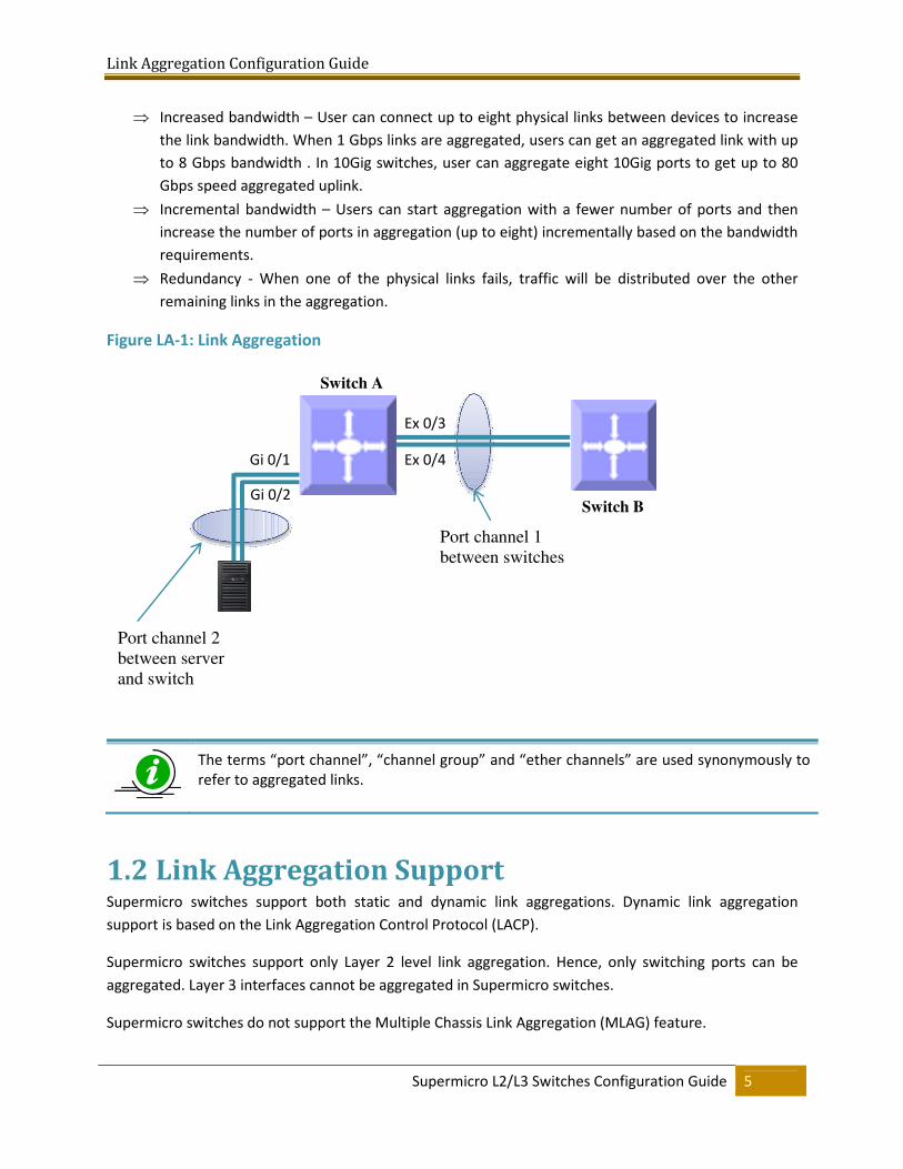
Figure LA-1: Link Aggregation
The terms “port channel”, “channel group” and “ether channels” are used synonymously to
refer to aggregated links.
1.2 Link Aggregation Support Supermicro switches support both static and dynamic link aggregations. Dynamic link aggregation
support is based on the Link Aggregation Control Protocol (LACP).
Supermicro switches support only Layer 2 level link aggregation. Hence, only switching ports can be
aggregated. Layer 3 interfaces cannot be aggregated in Supermicro switches.
Supermicro switches do not support the Multiple Chassis Link Aggregation (MLAG) feature.
Switch B
Switch A
Port channel 1
between switches
Ex 0/3
Ex 0/4 Gi 0/1
Gi 0/2
Port channel 2
between server
and switch
Link Aggregation Configuration Guide
Supermicro L2/L3 Switches Configuration Guide 6
1.3 Link Aggregation Numbers Supermicro switches support up to 24 port channels.
Each port channel can have eight active links.
Users can configure more than eight ports to a LACP mode port channel. However, a
maximum of eight ports only can be in an active bundle state in any port channel.
1.4 Link Aggregation Defaults The Link Aggregation feature is enabled by default in Supermicro switches.
When a port channel interface is created, it will be added to VLAN 1 by default.
Port channels use the MAC address of the first physical link added to it.
The default LACP system priority is 32768.
The default LACP port priority is 128.
The default LACP timeout is long (30 seconds).
The default LACP wait time is 2 seconds.
1.5 Static Link Aggregation Supermicro switches support static link aggregation.
User can add up to eight ports to a static port channel group. When the physical link status of one or
more ports in a channel group is up, that port channel status will be up. The port channel status will be
down when the ports physical link status of all members are down.
Switches do not exchange any port channel control information with other end devices in static link
aggregation. Hence, users need to configure the port channel groups and member ports correctly on
both end devices.
1.6 Dynamic Link Aggregation - LACP Supermicro switches support dynamic link aggregation through IEEE 802.3ad Link Aggregation Control
Protocol (LACP).
Link Aggregation Configuration Guide
Supermicro L2/L3 Switches Configuration Guide 7
Users can add one or more ports to an LACP mode port channel. When more than eight member ports
are configured, only the first eight member ports reaching “bundle” state will be used for data traffic.
Ports in LACP mode exchange LACP packets with other end device. The LACP system priority, switch
MAC address, port LACP priority, port number and aggregation key are all exchanged between devices.
Based on the exchanged information, both end devices agree on the status of the member ports. The
member ports that successfully negotiated LACP parameters will be moved to the “bundle” state. The
member ports that could not reach agreement on LACP parameters will stay in the “independent” state.
Switches do not send traffic on member ports in “independent” state.
When one or more member ports reach the “bundle” state, the port channel status will be up. The port
channel status will be down when all its member ports are either physically down or in the
“ndependent” state.
Ports can be configured in either active or passive LACP mode. Ports in active LACP mode will initiate
LACP negotiation by sending LACP messages to the other end devices. Ports in passive LACP mode will
not initiate the LACP negotiation, but they will respond to LACP messages if received from other end
devices.
Users should configure for an active LACP mode on at least one end of the LACP port
channel connection. If LACP mode is configured as passive on both end devices, the port
channel interface will not come up. Configuring LACP mode as active on both the end
devices is allowed.
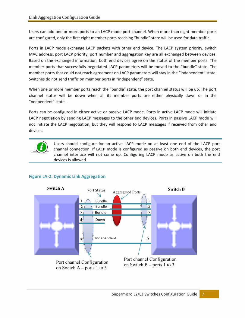
Figure LA-2: Dynamic Link Aggregation
Switch B Switch A
Port channel Configuration
on Switch A – ports 1 to 5
2
3
4
5
1
2
3
Port channel Configuration
on Switch B – ports 1 to 3
Bundle Bundle
Bundle
Down
Independent
Port Status Aggregated Ports
5
1
Link Aggregation Configuration Guide
Supermicro L2/L3 Switches Configuration Guide 8
Figure LA-2: Dynamic Link Aggregation shows an example of a port channel configuration with port
status and aggregated ports. In this example, port 5 is not configured on LACP mode on switch B, and is
therefore shown as being in the “independent” state and not part of the aggregated ports.
1.7 Creating Port Channels Port channel creation involves two steps: the first step is creating the port channel interfaces and the
second step is adding member ports to the port channel interfaces.
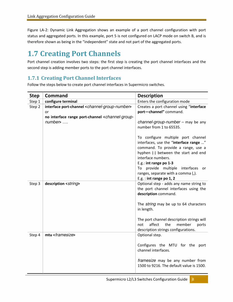
1.7.1 Creating Port Channel Interfaces Follow the steps below to create port channel interfaces in Supermicro switches.
Step Command Description Step 1 configure terminal Enters the configuration mode
Step 2 interface port-channel <channel-group-number>
or
no interface range port-channel <channel-group-
number> ….
Creates a port channel using “interface
port—channel” command.
channel-group-number – may be any
number from 1 to 65535.
To configure multiple port channel
interfaces, use the “interface range …”
command. To provide a range, use a
hyphen (-) between the start and end
interface numbers.
E.g.: int range po 1-3
To provide multiple interfaces or
ranges, separate with a comma (,).
E.g. : int range po 1, 2
Step 3 description <string> Optional step - adds any name string to
the port channel interfaces using the
description command.
The string may be up to 64 characters
in length.
The port channel description strings will
not affect the member ports
description strings configurations.
Step 4 mtu <framesize> Optional step.
Configures the MTU for the port
channel interfaces.
framesize may be any number from
1500 to 9216. The default value is 1500.
Link Aggregation Configuration Guide
Supermicro L2/L3 Switches Configuration Guide 9
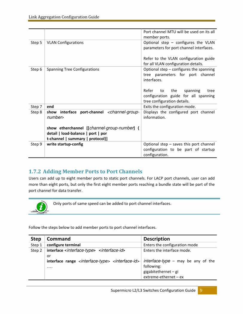
Port channel MTU will be used on its all
member ports.
Step 5 VLAN Configurations Optional step – configures the VLAN
parameters for port channel interfaces.
Refer to the VLAN configuration guide
for all VLAN configuration details.
Step 6 Spanning Tree Configurations Optional step – configures the spanning
tree parameters for port channel
interfaces.
Refer to the spanning tree
configuration guide for all spanning
tree configuration details.
Step 7 end Exits the configuration mode.
Step 8 show interface port-channel <channel-group-
number>
show etherchannel [[channel-group-number] {
detail | load-balance | port | por
t-channel | summary | protocol}]
Displays the configured port channel
information.
Step 9 write startup-config Optional step – saves this port channel
configuration to be part of startup
configuration.
1.7.2 Adding Member Ports to Port Channels Users can add up to eight member ports to static port channels. For LACP port channels, user can add
more than eight ports, but only the first eight member ports reaching a bundle state will be part of the
port channel for data transfer.
Only ports of same speed can be added to port channel interfaces.
Follow the steps below to add member ports to port channel interfaces.
Step Command Description Step 1 configure terminal Enters the configuration mode
Step 2 interface <interface-type> <interface-id>
or
interface range <interface-type> <interface-id>
….
Enters the interface mode.
interface-type – may be any of the
following:
gigabitethernet – gi
extreme-ethernet – ex
Link Aggregation Configuration Guide
Supermicro L2/L3 Switches Configuration Guide 10
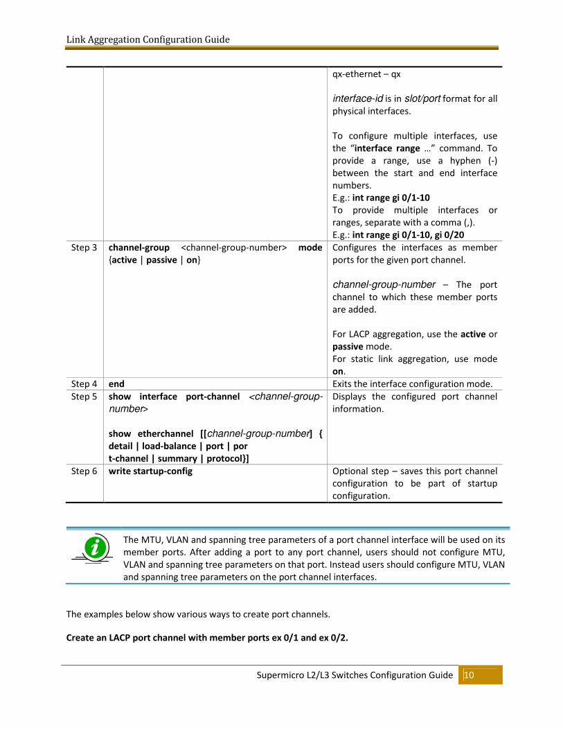
qx-ethernet – qx
interface-id is in slot/port format for all
physical interfaces.
To configure multiple interfaces, use
the “interface range …” command. To
provide a range, use a hyphen (-)
between the start and end interface
numbers.
E.g.: int range gi 0/1-10
To provide multiple interfaces or
ranges, separate with a comma (,).
E.g.: int range gi 0/1-10, gi 0/20
Step 3 channel-group <channel-group-number> mode
{active | passive | on}
Configures the interfaces as member
ports for the given port channel.
channel-group-number – The port
channel to which these member ports
are added.
For LACP aggregation, use the active or
passive mode.
For static link aggregation, use mode
on.
Step 4 end Exits the interface configuration mode.
Step 5 show interface port-channel <channel-group-
number>
show etherchannel [[channel-group-number] {
detail | load-balance | port | por
t-channel | summary | protocol}]
Displays the configured port channel
information.
Step 6 write startup-config Optional step – saves this port channel
configuration to be part of startup
configuration.
The MTU, VLAN and spanning tree parameters of a port channel interface will be used on its
member ports. After adding a port to any port channel, users should not configure MTU,
VLAN and spanning tree parameters on that port. Instead users should configure MTU, VLAN
and spanning tree parameters on the port channel interfaces.
The examples below show various ways to create port channels.
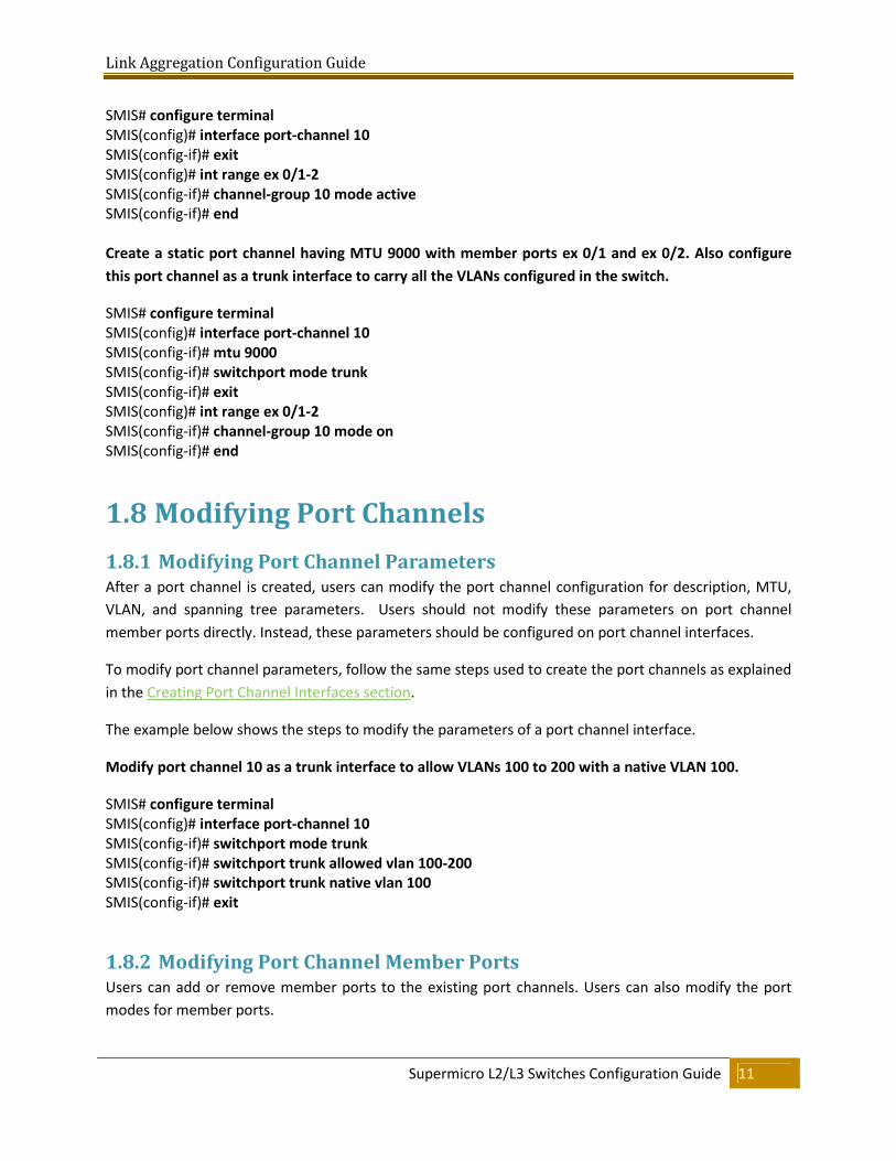
Create an LACP port channel with member ports ex 0/1 and ex 0/2.
Link Aggregation Configuration Guide
Supermicro L2/L3 Switches Configuration Guide 11
SMIS# configure terminal
SMIS(config)# interface port-channel 10
SMIS(config-if)# exit
SMIS(config)# int range ex 0/1-2
SMIS(config-if)# channel-group 10 mode active
SMIS(config-if)# end
Create a static port channel having MTU 9000 with member ports ex 0/1 and ex 0/2. Also configure
this port channel as a trunk interface to carry all the VLANs configured in the switch.
SMIS# configure terminal
SMIS(config)# interface port-channel 10
SMIS(config-if)# mtu 9000
SMIS(config-if)# switchport mode trunk
SMIS(config-if)# exit
SMIS(config)# int range ex 0/1-2
SMIS(config-if)# channel-group 10 mode on
SMIS(config-if)# end
1.8 Modifying Port Channels
1.8.1 Modifying Port Channel Parameters After a port channel is created, users can modify the port channel configuration for description, MTU,
VLAN, and spanning tree parameters. Users should not modify these parameters on port channel
member ports directly. Instead, these parameters should be configured on port channel interfaces.
To modify port channel parameters, follow the same steps used to create the port channels as explained
in the Creating Port Channel Interfaces section.
The example below shows the steps to modify the parameters of a port channel interface.
Modify port channel 10 as a trunk interface to allow VLANs 100 to 200 with a native VLAN 100.
SMIS# configure terminal
SMIS(config)# interface port-channel 10
SMIS(config-if)# switchport mode trunk
SMIS(config-if)# switchport trunk allowed vlan 100-200
SMIS(config-if)# switchport trunk native vlan 100
SMIS(config-if)# exit
1.8.2 Modifying Port Channel Member Ports Users can add or remove member ports to the existing port channels. Users can also modify the port
modes for member ports.
Link Aggregation Configuration Guide
Supermicro L2/L3 Switches Configuration Guide 12
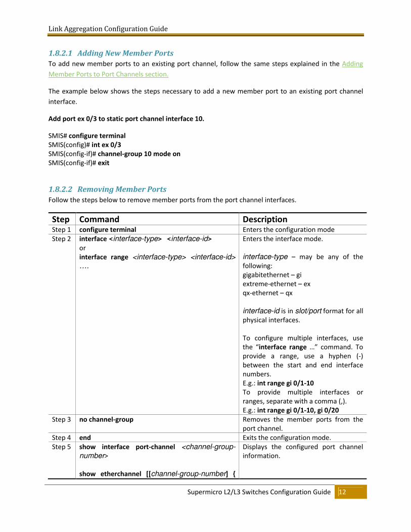
1.8.2.1 Adding New Member Ports
To add new member ports to an existing port channel, follow the same steps explained in the Adding
Member Ports to Port Channels section.
The example below shows the steps necessary to add a new member port to an existing port channel
interface.
Add port ex 0/3 to static port channel interface 10.
SMIS# configure terminal
SMIS(config)# int ex 0/3
SMIS(config-if)# channel-group 10 mode on
SMIS(config-if)# exit
1.8.2.2 Removing Member Ports
Follow the steps below to remove member ports from the port channel interfaces.
Step Command Description Step 1 configure terminal Enters the configuration mode
Step 2 interface <interface-type> <interface-id>
or
interface range <interface-type> <interface-id>
….
Enters the interface mode.
interface-type – may be any of the
following:
gigabitethernet – gi
extreme-ethernet – ex
qx-ethernet – qx
interface-id is in slot/port format for all
physical interfaces.
To configure multiple interfaces, use
the “interface range …” command. To
provide a range, use a hyphen (-)
between the start and end interface
numbers.
E.g.: int range gi 0/1-10
To provide multiple interfaces or
ranges, separate with a comma (,).
E.g.: int range gi 0/1-10, gi 0/20
Step 3 no channel-group Removes the member ports from the
port channel.
Step 4 end Exits the configuration mode.
Step 5 show interface port-channel <channel-group-
number>
show etherchannel [[channel-group-number] {
Displays the configured port channel
information.
Link Aggregation Configuration Guide
Supermicro L2/L3 Switches Configuration Guide 13
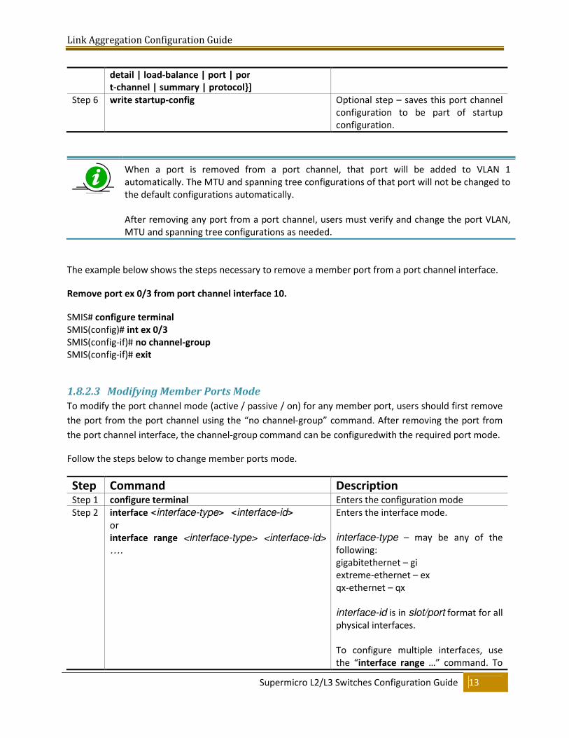
detail | load-balance | port | por
t-channel | summary | protocol}]
Step 6 write startup-config Optional step – saves this port channel
configuration to be part of startup
configuration.
When a port is removed from a port channel, that port will be added to VLAN 1
automatically. The MTU and spanning tree configurations of that port will not be changed to
the default configurations automatically.
After removing any port from a port channel, users must verify and change the port VLAN,
MTU and spanning tree configurations as needed.
The example below shows the steps necessary to remove a member port from a port channel interface.
Remove port ex 0/3 from port channel interface 10.
SMIS# configure terminal
SMIS(config)# int ex 0/3
SMIS(config-if)# no channel-group
SMIS(config-if)# exit
1.8.2.3 Modifying Member Ports Mode
To modify the port channel mode (active / passive / on) for any member port, users should first remove
the port from the port channel using the “no channel-group” command. After removing the port from
the port channel interface, the channel-group command can be configuredwith the required port mode.
Follow the steps below to change member ports mode.
Step Command Description Step 1 configure terminal Enters the configuration mode
Step 2 interface <interface-type> <interface-id>
or
interface range <interface-type> <interface-id>
….
Enters the interface mode.
interface-type – may be any of the
following:
gigabitethernet – gi
extreme-ethernet – ex
qx-ethernet – qx
interface-id is in slot/port format for all
physical interfaces.
To configure multiple interfaces, use
the “interface range …” command. To
Link Aggregation Configuration Guide
Supermicro L2/L3 Switches Configuration Guide 14
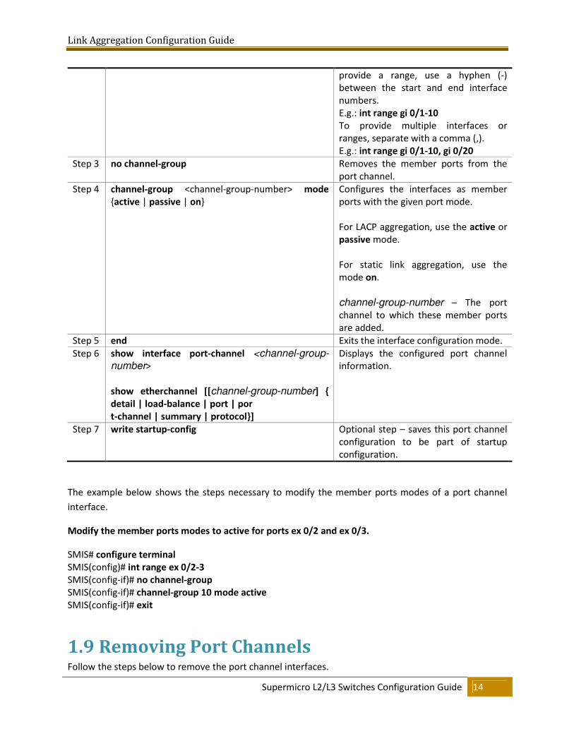
provide a range, use a hyphen (-)
between the start and end interface
numbers.
E.g.: int range gi 0/1-10
To provide multiple interfaces or
ranges, separate with a comma (,).
E.g.: int range gi 0/1-10, gi 0/20
Step 3 no channel-group Removes the member ports from the
port channel.
Step 4 channel-group <channel-group-number> mode
{active | passive | on}
Configures the interfaces as member
ports with the given port mode.
For LACP aggregation, use the active or
passive mode.
For static link aggregation, use the
mode on.
channel-group-number – The port
channel to which these member ports
are added.
Step 5 end Exits the interface configuration mode.
Step 6 show interface port-channel <channel-group-
number>
show etherchannel [[channel-group-number] {
detail | load-balance | port | por
t-channel | summary | protocol}]
Displays the configured port channel
information.
Step 7 write startup-config Optional step – saves this port channel
configuration to be part of startup
configuration.
The example below shows the steps necessary to modify the member ports modes of a port channel
interface.
Modify the member ports modes to active for ports ex 0/2 and ex 0/3.
SMIS# configure terminal
SMIS(config)# int range ex 0/2-3
SMIS(config-if)# no channel-group
SMIS(config-if)# channel-group 10 mode active
SMIS(config-if)# exit
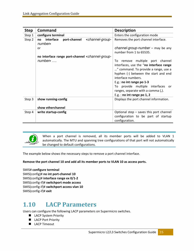
1.9 Removing Port Channels Follow the steps below to remove the port channel interfaces.
Link Aggregation Configuration Guide
Supermicro L2/L3 Switches Configuration Guide 15
Step Command Description Step 1 configure terminal Enters the configuration mode
Step 2 no interface port-channel <channel-group-
number>
or
no interface range port-channel <channel-group-
number> ….
Removes the port channel interface.
channel-group-number – may be any
number from 1 to 65535.
To remove multiple port channel
interfaces, use the “no interface range
…” command. To provide a range, use a
hyphen (-) between the start and end
interface numbers.
E.g.: no int range po 1-3
To provide multiple interfaces or
ranges, separate with a comma (,).
E.g. : no int range po 1, 2
Step 3 show running-config
show etherchannel
Displays the port channel information.
Step 4 write startup-config Optional step – saves this port channel
configuration to be part of startup
configuration.
When a port channel is removed, all its member ports will be added to VLAN 1
automatically. The MTU and spanning tree configurations of that port will not automatically
be changed to default configurations.
The example below shows the necessary steps to remove a port channel interface.
Remove the port channel 10 and add all its member ports to VLAN 10 as access ports.
SMIS# configure terminal
SMIS(config)# no int port-channel 10
SMIS(config)# interface range ex 0/1-2
SMIS(config-if)# switchport mode access
SMIS(config-if)# switchport access vlan 10
SMIS(config-if)# exit
1.10 LACP Parameters Users can configure the following LACP parameters on Supermicro switches.
� LACP System Priority
� LACP Port Priority
� LACP Timeout
Link Aggregation Configuration Guide
Supermicro L2/L3 Switches Configuration Guide 16
� LACP Wait Time
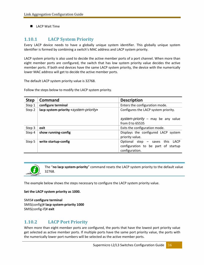
1.10.1 LACP System Priority Every LACP device needs to have a globally unique system identifier. This globally unique system
identifier is formed by combining a switch’s MAC address and LACP system priority.
LACP system priority is also used to decide the active member ports of a port channel. When more than
eight member ports are configured, the switch that has low system priority value decides the active
member ports. If both end devices have the same LACP system priority, the device with the numerically
lower MAC address will get to decide the active member ports.
The default LACP system priority value is 32768.
Follow the steps below to modify the LACP system priority.
Step Command Description Step 1 configure terminal Enters the configuration mode.
Step 2 lacp system-priority <system-priority>
Configures the LACP system priority.
system-priority – may be any value
from 0 to 65535
Step 3 exit Exits the configuration mode.
Step 4 show running-config Displays the configured LACP system
priority value.
Step 5 write startup-config Optional step – saves this LACP
configuration to be part of startup
configuration.
The “no lacp system-priority” command resets the LACP system priority to the default value
32768.
The example below shows the steps necessary to configure the LACP system priority value.
Set the LACP system priority as 1000.
SMIS# configure terminal
SMIS(config)# lacp system-priority 1000
SMIS(config-if)# exit
1.10.2 LACP Port Priority When more than eight member ports are configured, the ports that have the lowest port priority value
get selected as active member ports. If multiple ports have the same port priority value, the ports with
the numerically lower port numbers will be selected as the active member ports.
Link Aggregation Configuration Guide
Supermicro L2/L3 Switches Configuration Guide 17
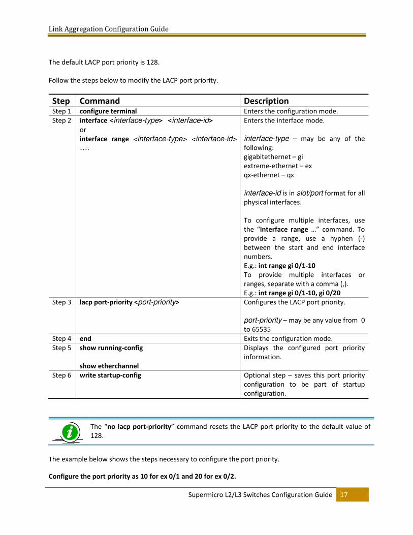
The default LACP port priority is 128.
Follow the steps below to modify the LACP port priority.
Step Command Description Step 1 configure terminal Enters the configuration mode.
Step 2 interface <interface-type> <interface-id>
or
interface range <interface-type> <interface-id>
….
Enters the interface mode.
interface-type – may be any of the
following:
gigabitethernet – gi
extreme-ethernet – ex
qx-ethernet – qx
interface-id is in slot/port format for all
physical interfaces.
To configure multiple interfaces, use
the “interface range …” command. To
provide a range, use a hyphen (-)
between the start and end interface
numbers.
E.g.: int range gi 0/1-10
To provide multiple interfaces or
ranges, separate with a comma (,).
E.g.: int range gi 0/1-10, gi 0/20
Step 3 lacp port-priority <port-priority>
Configures the LACP port priority.
port-priority – may be any value from 0
to 65535
Step 4 end Exits the configuration mode.
Step 5 show running-config
show etherchannel
Displays the configured port priority
information.
Step 6 write startup-config Optional step – saves this port priority
configuration to be part of startup
configuration.
The “no lacp port-priority” command resets the LACP port priority to the default value of
128.
The example below shows the steps necessary to configure the port priority.
Configure the port priority as 10 for ex 0/1 and 20 for ex 0/2.
Link Aggregation Configuration Guide
Supermicro L2/L3 Switches Configuration Guide 18
SMIS# configure terminal
SMIS(config)# interface ex 0/1
SMIS(config-if)# lacp port-priority 10
SMIS(config-if)# exit
SMIS(config)# interface ex 0/2
SMIS(config-if)# lacp port-priority 20
SMIS(config-if)# exit
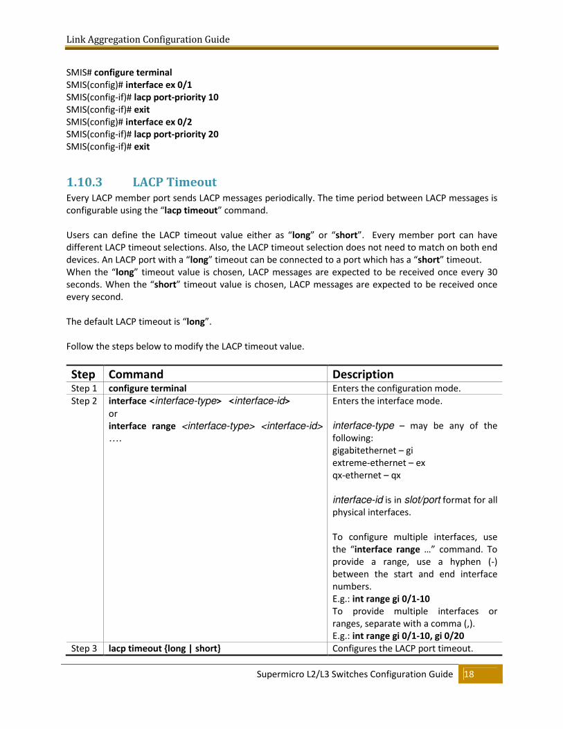
1.10.3 LACP Timeout Every LACP member port sends LACP messages periodically. The time period between LACP messages is
configurable using the “lacp timeout” command.
Users can define the LACP timeout value either as “long” or “short”. Every member port can have
different LACP timeout selections. Also, the LACP timeout selection does not need to match on both end
devices. An LACP port with a “long” timeout can be connected to a port which has a “short” timeout.
When the “long” timeout value is chosen, LACP messages are expected to be received once every 30
seconds. When the “short” timeout value is chosen, LACP messages are expected to be received once
every second.
The default LACP timeout is “long”.
Follow the steps below to modify the LACP timeout value.
Step Command Description Step 1 configure terminal Enters the configuration mode.
Step 2 interface <interface-type> <interface-id>
or
interface range <interface-type> <interface-id>
….
Enters the interface mode.
interface-type – may be any of the
following:
gigabitethernet – gi
extreme-ethernet – ex
qx-ethernet – qx
interface-id is in slot/port format for all
physical interfaces.
To configure multiple interfaces, use
the “interface range …” command. To
provide a range, use a hyphen (-)
between the start and end interface
numbers.
E.g.: int range gi 0/1-10
To provide multiple interfaces or
ranges, separate with a comma (,).
E.g.: int range gi 0/1-10, gi 0/20
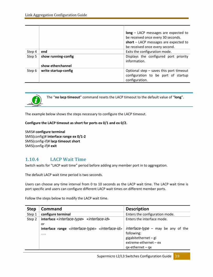
Step 3 lacp timeout {long | short} Configures the LACP port timeout.
Link Aggregation Configuration Guide
Supermicro L2/L3 Switches Configuration Guide 19
long – LACP messages are expected to
be received once every 30 seconds.
short – LACP messages are expected to
be received once every second.
Step 4 end Exits the configuration mode.
Step 5 show running-config
show etherchannel
Displays the configured port priority
information.
Step 6 write startup-config Optional step – saves this port timeout
configuration to be part of startup
configuration.
The “no lacp timeout” command resets the LACP timeout to the default value of “long”.
The example below shows the steps necessary to configure the LACP timeout.
Configure the LACP timeout as short for ports ex 0/1 and ex 0/2.
SMIS# configure terminal
SMIS(config)# interface range ex 0/1-2
SMIS(config-if)# lacp timeout short
SMIS(config-if)# exit
1.10.4 LACP Wait Time Switch waits for “LACP wait time” period before adding any member port in to aggregation.
The default LACP wait time period is two seconds.
Users can choose any time interval from 0 to 10 seconds as the LACP wait time. The LACP wait time is
port specific and users can configure different LACP wait times on different member ports.
Follow the steps below to modify the LACP wait time.
Step Command Description Step 1 configure terminal Enters the configuration mode.
Step 2 interface <interface-type> <interface-id>
or
interface range <interface-type> <interface-id>
….
Enters the interface mode.
interface-type – may be any of the
following:
gigabitethernet – gi
extreme-ethernet – ex
qx-ethernet – qx
Link Aggregation Configuration Guide
Supermicro L2/L3 Switches Configuration Guide 20
interface-id is in slot/port format for all
physical interfaces.
To configure multiple interfaces, use
the “interface range …” command. To
provide a range, use a hyphen (-)
between the start and end interface
numbers.
E.g.: int range gi 0/1-10
To provide multiple interfaces or
ranges, separate with a comma (,).
E.g.: int range gi 0/1-10, gi 0/20
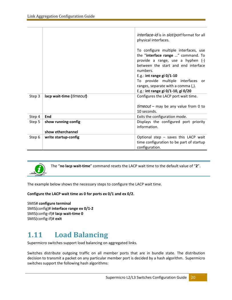
Step 3 lacp wait-time {timeout}
Configures the LACP port wait time.
timeout – may be any value from 0 to
10 seconds.
Step 4 End Exits the configuration mode.
Step 5 show running-config
show etherchannel
Displays the configured port priority
information.
Step 6 write startup-config Optional step – saves this LACP wait
time configuration to be part of startup
configuration.
The “no lacp wait-time” command resets the LACP wait time to the default value of “2”.
The example below shows the necessary steps to configure the LACP wait time.
Configure the LACP wait time as 0 for ports ex 0/1 and ex 0/2.
SMIS# configure terminal
SMIS(config)# interface range ex 0/1-2
SMIS(config-if)# lacp wait-time 0
SMIS(config-if)# exit
1.11 Load Balancing Supermicro switches support load balancing on aggregated links.
Switches distribute outgoing traffic on all member ports that are in bundle state. The distribution
decision to transmit a packet on any particular member port is decided by a hash algorithm. Supermicro
switches support the following hash algorithms:
Link Aggregation Configuration Guide
Supermicro L2/L3 Switches Configuration Guide 21
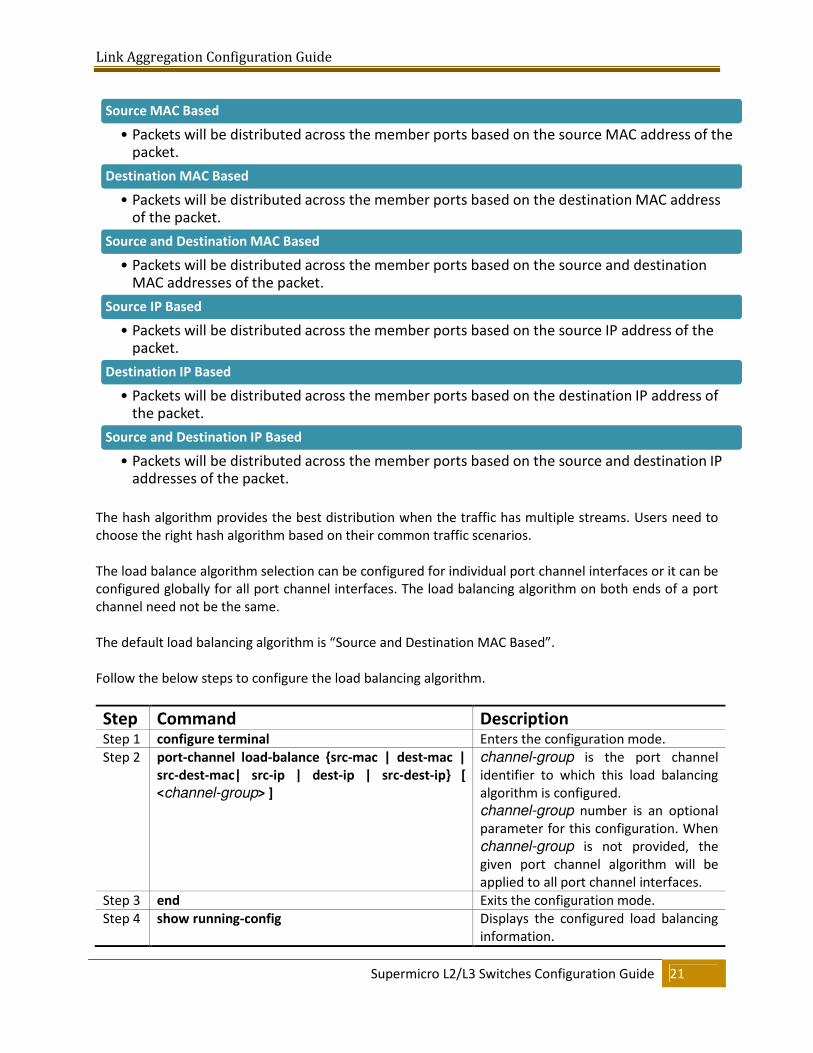
The hash algorithm provides the best distribution when the traffic has multiple streams. Users need to
choose the right hash algorithm based on their common traffic scenarios.
The load balance algorithm selection can be configured for individual port channel interfaces or it can be
configured globally for all port channel interfaces. The load balancing algorithm on both ends of a port
channel need not be the same.
The default load balancing algorithm is “Source and Destination MAC Based”.
Follow the below steps to configure the load balancing algorithm.
Step Command Description Step 1 configure terminal Enters the configuration mode.
Step 2 port-channel load-balance {src-mac | dest-mac |
src-dest-mac| src-ip | dest-ip | src-dest-ip} [
<channel-group> ]
channel-group is the port channel
identifier to which this load balancing
algorithm is configured.
channel-group number is an optional
parameter for this configuration. When
channel-group is not provided, the
given port channel algorithm will be
applied to all port channel interfaces.
Step 3 end Exits the configuration mode.
Step 4 show running-config Displays the configured load balancing
information.
Source MAC Based
• Packets will be distributed across the member ports based on the source MAC address of the packet.
Destination MAC Based
• Packets will be distributed across the member ports based on the destination MAC address of the packet.
Source and Destination MAC Based
• Packets will be distributed across the member ports based on the source and destination MAC addresses of the packet.
Source IP Based
• Packets will be distributed across the member ports based on the source IP address of the packet.
Destination IP Based
• Packets will be distributed across the member ports based on the destination IP address of the packet.
Source and Destination IP Based
• Packets will be distributed across the member ports based on the source and destination IP addresses of the packet.
Link Aggregation Configuration Guide
Supermicro L2/L3 Switches Configuration Guide 22
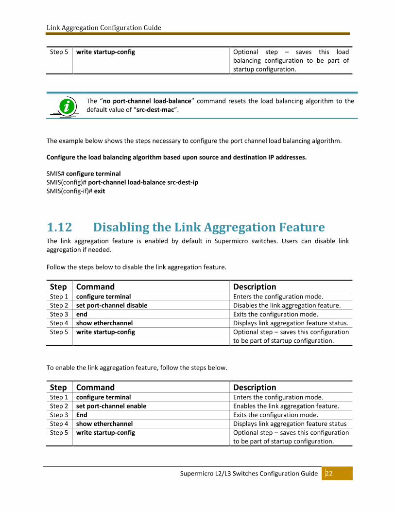
Step 5 write startup-config Optional step – saves this load
balancing configuration to be part of
startup configuration.
The “no port-channel load-balance” command resets the load balancing algorithm to the
default value of “src-dest-mac”.
The example below shows the steps necessary to configure the port channel load balancing algorithm.
Configure the load balancing algorithm based upon source and destination IP addresses.
SMIS# configure terminal
SMIS(config)# port-channel load-balance src-dest-ip
SMIS(config-if)# exit
1.12 Disabling the Link Aggregation Feature The link aggregation feature is enabled by default in Supermicro switches. Users can disable link
aggregation if needed.
Follow the steps below to disable the link aggregation feature.
Step Command Description Step 1 configure terminal Enters the configuration mode.
Step 2 set port-channel disable Disables the link aggregation feature.
Step 3 end Exits the configuration mode.
Step 4 show etherchannel Displays link aggregation feature status.
Step 5 write startup-config Optional step – saves this configuration
to be part of startup configuration.
To enable the link aggregation feature, follow the steps below.
Step Command Description Step 1 configure terminal Enters the configuration mode.
Step 2 set port-channel enable Enables the link aggregation feature.
Step 3 End Exits the configuration mode.
Step 4 show etherchannel Displays link aggregation feature status
Step 5 write startup-config Optional step – saves this configuration
to be part of startup configuration.
Link Aggregation Configuration Guide
Supermicro L2/L3 Switches Configuration Guide 23
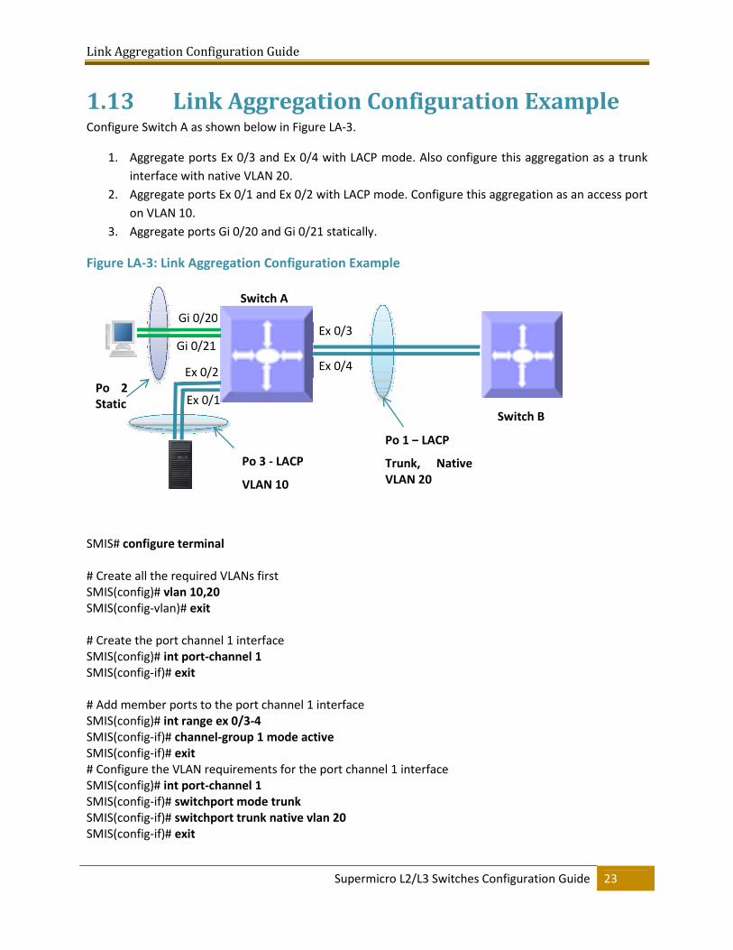
1.13 Link Aggregation Configuration Example Configure Switch A as shown below in Figure LA-3.
1. Aggregate ports Ex 0/3 and Ex 0/4 with LACP mode. Also configure this aggregation as a trunk
interface with native VLAN 20.
2. Aggregate ports Ex 0/1 and Ex 0/2 with LACP mode. Configure this aggregation as an access port
on VLAN 10.
3. Aggregate ports Gi 0/20 and Gi 0/21 statically.
Figure LA-3: Link Aggregation Configuration Example
SMIS# configure terminal
# Create all the required VLANs first
SMIS(config)# vlan 10,20
SMIS(config-vlan)# exit
# Create the port channel 1 interface
SMIS(config)# int port-channel 1
SMIS(config-if)# exit
# Add member ports to the port channel 1 interface
SMIS(config)# int range ex 0/3-4
SMIS(config-if)# channel-group 1 mode active
SMIS(config-if)# exit
# Configure the VLAN requirements for the port channel 1 interface
SMIS(config)# int port-channel 1
SMIS(config-if)# switchport mode trunk
SMIS(config-if)# switchport trunk native vlan 20
SMIS(config-if)# exit
Switch B
Switch A
Po 1 – LACP
Trunk, Native
VLAN 20
Ex 0/1
Gi 0/20 Ex 0/3
Ex 0/4
Gi 0/21
Ex 0/2 Po 2
Static
Po 3 - LACP
VLAN 10
Link Aggregation Configuration Guide
Supermicro L2/L3 Switches Configuration Guide 24
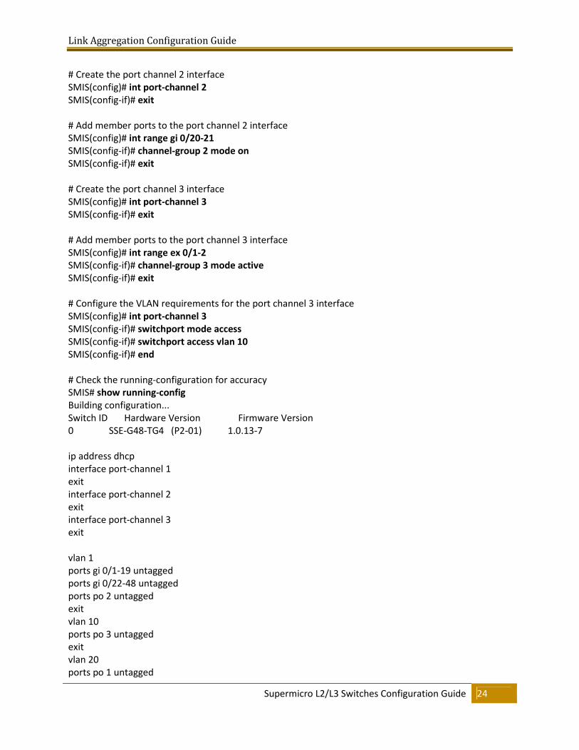
# Create the port channel 2 interface
SMIS(config)# int port-channel 2
SMIS(config-if)# exit
# Add member ports to the port channel 2 interface
SMIS(config)# int range gi 0/20-21
SMIS(config-if)# channel-group 2 mode on
SMIS(config-if)# exit
# Create the port channel 3 interface
SMIS(config)# int port-channel 3
SMIS(config-if)# exit
# Add member ports to the port channel 3 interface
SMIS(config)# int range ex 0/1-2
SMIS(config-if)# channel-group 3 mode active
SMIS(config-if)# exit
# Configure the VLAN requirements for the port channel 3 interface
SMIS(config)# int port-channel 3
SMIS(config-if)# switchport mode access
SMIS(config-if)# switchport access vlan 10
SMIS(config-if)# end
# Check the running-configuration for accuracy
SMIS# show running-config
Building configuration...
Switch ID Hardware Version Firmware Version
0 SSE-G48-TG4 (P2-01) 1.0.13-7
ip address dhcp
interface port-channel 1
exit
interface port-channel 2
exit
interface port-channel 3
exit
vlan 1
ports gi 0/1-19 untagged
ports gi 0/22-48 untagged
ports po 2 untagged
exit
vlan 10
ports po 3 untagged
exit
vlan 20
ports po 1 untagged
Link Aggregation Configuration Guide
Supermicro L2/L3 Switches Configuration Guide 25
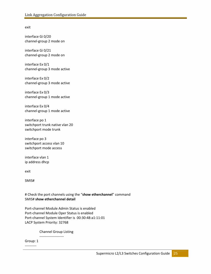
exit
interface Gi 0/20
channel-group 2 mode on
interface Gi 0/21
channel-group 2 mode on
interface Ex 0/1
channel-group 3 mode active
interface Ex 0/2
channel-group 3 mode active
interface Ex 0/3
channel-group 1 mode active
interface Ex 0/4
channel-group 1 mode active
interface po 1
switchport trunk native vlan 20
switchport mode trunk
interface po 3
switchport access vlan 10
switchport mode access
interface vlan 1
ip address dhcp
exit
SMIS#
# Check the port channels using the “show etherchannel” command
SMIS# show etherchannel detail
Port-channel Module Admin Status is enabled
Port-channel Module Oper Status is enabled
Port-channel System Identifier is 00:30:48:a1:11:01
LACP System Priority: 32768
Channel Group Listing
---------------------
Group: 1
----------
Link Aggregation Configuration Guide
Supermicro L2/L3 Switches Configuration Guide 26
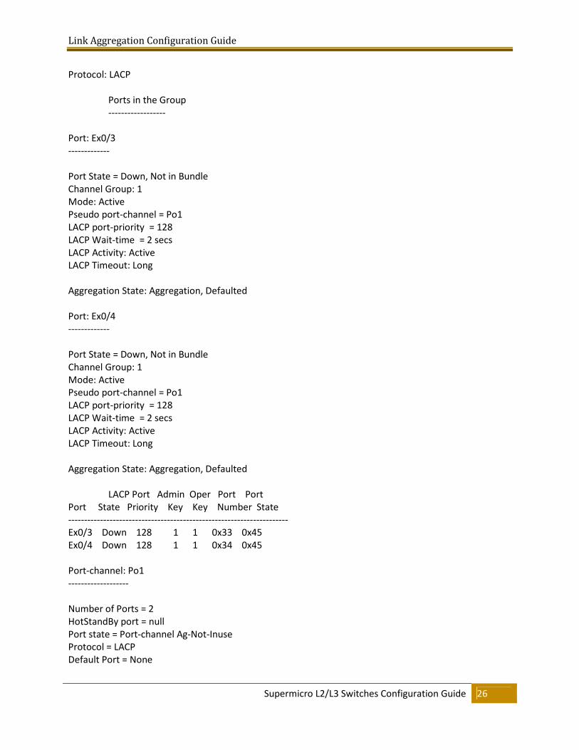
Protocol: LACP
Ports in the Group
------------------
Port: Ex0/3
-------------
Port State = Down, Not in Bundle
Channel Group: 1
Mode: Active
Pseudo port-channel = Po1
LACP port-priority = 128
LACP Wait-time = 2 secs
LACP Activity: Active
LACP Timeout: Long
Aggregation State: Aggregation, Defaulted
Port: Ex0/4
-------------
Port State = Down, Not in Bundle
Channel Group: 1
Mode: Active
Pseudo port-channel = Po1
LACP port-priority = 128
LACP Wait-time = 2 secs
LACP Activity: Active
LACP Timeout: Long
Aggregation State: Aggregation, Defaulted
LACP Port Admin Oper Port Port
Port State Priority Key Key Number State
---------------------------------------------------------------------
Ex0/3 Down 128 1 1 0x33 0x45
Ex0/4 Down 128 1 1 0x34 0x45
Port-channel: Po1
-------------------
Number of Ports = 2
HotStandBy port = null
Port state = Port-channel Ag-Not-Inuse
Protocol = LACP
Default Port = None
Link Aggregation Configuration Guide
Supermicro L2/L3 Switches Configuration Guide 27
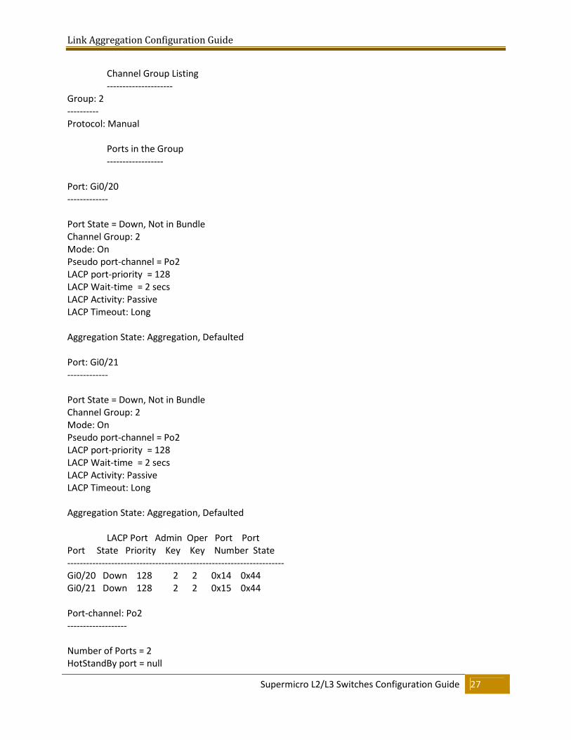
Channel Group Listing
---------------------
Group: 2
----------
Protocol: Manual
Ports in the Group
------------------
Port: Gi0/20
-------------
Port State = Down, Not in Bundle
Channel Group: 2
Mode: On
Pseudo port-channel = Po2
LACP port-priority = 128
LACP Wait-time = 2 secs
LACP Activity: Passive
LACP Timeout: Long
Aggregation State: Aggregation, Defaulted
Port: Gi0/21
-------------
Port State = Down, Not in Bundle
Channel Group: 2
Mode: On
Pseudo port-channel = Po2
LACP port-priority = 128
LACP Wait-time = 2 secs
LACP Activity: Passive
LACP Timeout: Long
Aggregation State: Aggregation, Defaulted
LACP Port Admin Oper Port Port
Port State Priority Key Key Number State
---------------------------------------------------------------------
Gi0/20 Down 128 2 2 0x14 0x44
Gi0/21 Down 128 2 2 0x15 0x44
Port-channel: Po2
-------------------
Number of Ports = 2
HotStandBy port = null
Link Aggregation Configuration Guide
Supermicro L2/L3 Switches Configuration Guide 28
Port state = Port-channel Ag-Not-Inuse
Protocol = Manual
Default Port = None
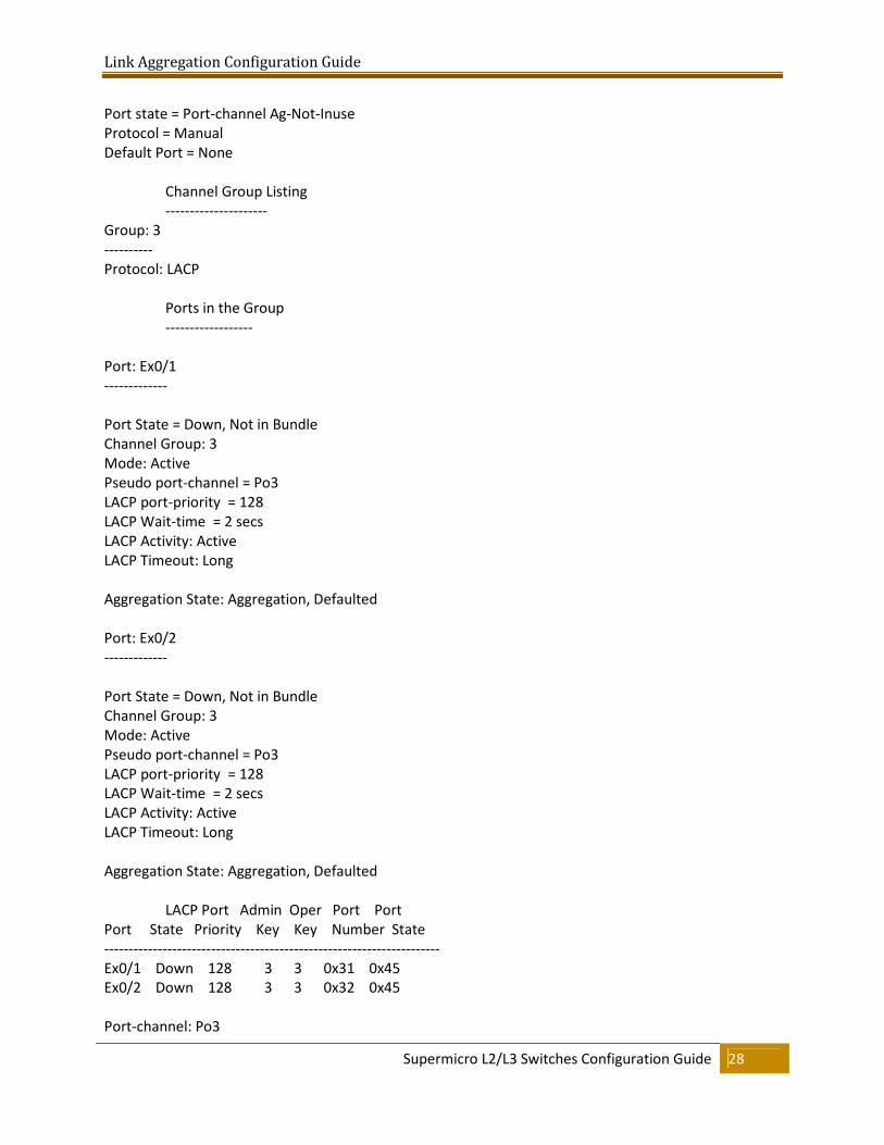
Channel Group Listing
---------------------
Group: 3
----------
Protocol: LACP
Ports in the Group
------------------
Port: Ex0/1
-------------
Port State = Down, Not in Bundle
Channel Group: 3
Mode: Active
Pseudo port-channel = Po3
LACP port-priority = 128
LACP Wait-time = 2 secs
LACP Activity: Active
LACP Timeout: Long
Aggregation State: Aggregation, Defaulted
Port: Ex0/2
-------------
Port State = Down, Not in Bundle
Channel Group: 3
Mode: Active
Pseudo port-channel = Po3
LACP port-priority = 128
LACP Wait-time = 2 secs
LACP Activity: Active
LACP Timeout: Long
Aggregation State: Aggregation, Defaulted
LACP Port Admin Oper Port Port
Port State Priority Key Key Number State
---------------------------------------------------------------------
Ex0/1 Down 128 3 3 0x31 0x45
Ex0/2 Down 128 3 3 0x32 0x45
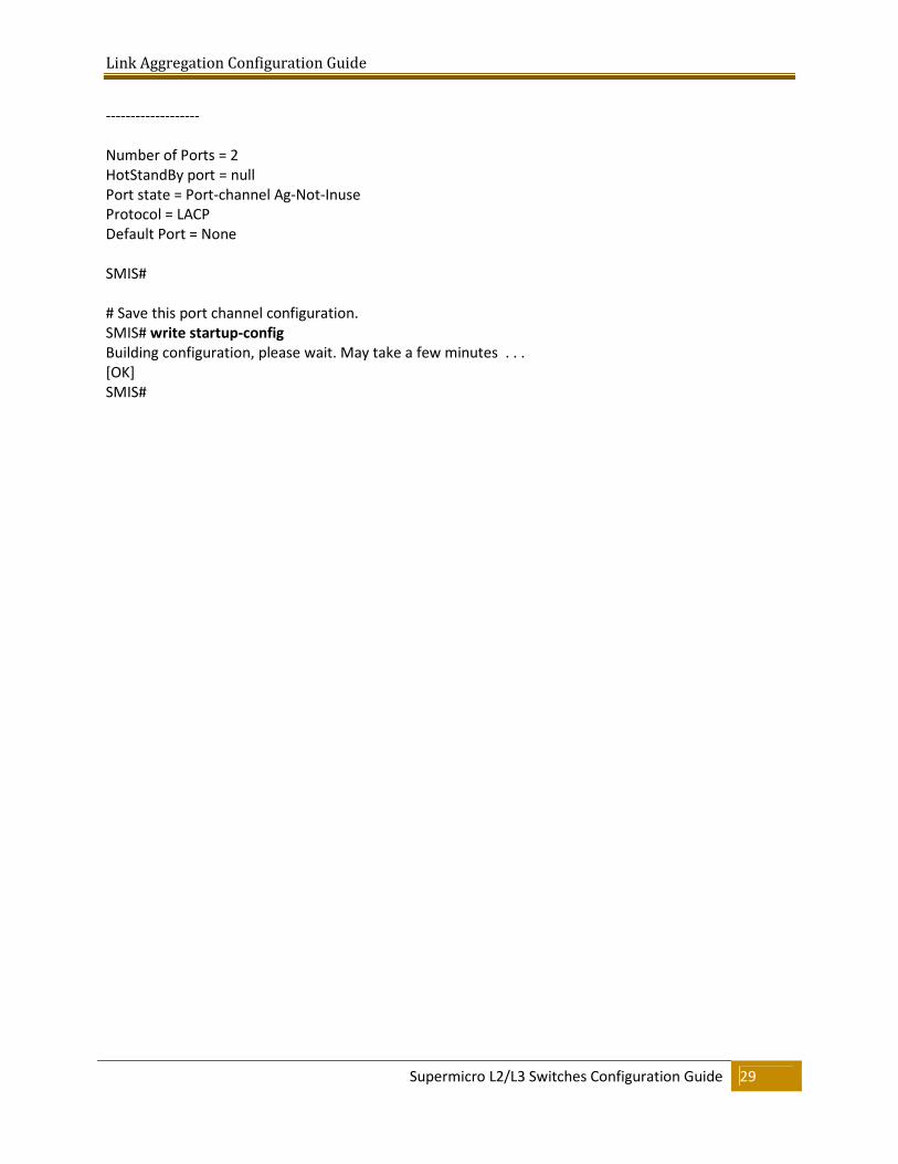
Port-channel: Po3
Link Aggregation Configuration Guide
Supermicro L2/L3 Switches Configuration Guide 29
-------------------
Number of Ports = 2
HotStandBy port = null
Port state = Port-channel Ag-Not-Inuse
Protocol = LACP
Default Port = None
SMIS#
# Save this port channel configuration.
SMIS# write startup-config
Building configuration, please wait. May take a few minutes . . .
[OK]
SMIS#