Embed Size (px)
DESCRIPTION
Service Manual Canon Fax L-140
Citation preview

Feb 6 2008
Service Manual
L90/L140/L160/L230 SeriesFAX-L140

ApplicationThis manual has been issued by Canon Inc. for qualified persons to learn technical theory, installation, maintenance, and repair
of products. This manual covers all localities where the products are sold. For this reason, there may be information in this
manual that does not apply to your locality.
CorrectionsThis manual may contain technical inaccuracies or typographical errors due to improvements or changes in products. When
changes occur in applicable products or in the contents of this manual, Canon will release technical information as the need
arises. In the event of major changes in the contents of this manual over a long or short period, Canon will issue a new edition
of this manual.
The following paragraph does not apply to any countries where such provisions are inconsistent with local law.
TrademarksThe product names and company names used in this manual are the registered trademarks of the individual companies.
CopyrightThis manual is copyrighted with all rights reserved. Under the copyright laws, this manual may not be copied, reproduced or
translated into another language, in whole or in part, without the written consent of Canon Inc.
COPYRIGHT © 2001 CANON INC.Printed in Japan
CautionUse of this manual should be strictly supervised to avoid disclosure of confidential information.
Introduction
Symbols UsedThis documentation uses the following symbols to indicate special information:
Symbol Description
Indicates an item of a non-specific nature, possibly classified as Note, Caution, or Warning.
Indicates an item requiring care to avoid electric shocks.
Indicates an item requiring care to avoid combustion (fire).
Indicates an item prohibiting disassembly to avoid electric shocks or problems.
Indicates an item requiring disconnection of the power plug from the electric outlet.
Indicates an item intended to provide notes assisting the understanding of the topic in question.
Indicates an item of reference assisting the understanding of the topic in question.
Provides a description of a service mode.
Provides a description of the nature of an error indication.
Memo
REF.

Introduction
The following rules apply throughout this Service Manual:1. Each chapter contains sections explaining the purpose of specific functions and the relationship between electrical and mechanical systems with refer-
ence to the timing of operation.In the diagrams, represents the path of mechanical drive; where a signal name accompanies the symbol , the arrow indicates thedirection of the electric signal.The expression "turn on the power" means flipping on the power switch, closing the front door, and closing the delivery unit door, which results insupplying the machine with power.
2. In the digital circuits, '1'is used to indicate that the voltage level of a given signal is "High", while '0' is used to indicate "Low".(The voltage value, how-ever, differs from circuit to circuit.) In addition, the asterisk (*) as in "DRMD*" indicates that the DRMD signal goes on when '0'.In practically all cases, the internal mechanisms of a microprocessor cannot be checked in the field. Therefore, the operations of the microprocessorsused in the machines are not discussed: they are explained in terms of from sensors to the input of the DC controller PCB and from the output of theDC controller PCB to the loads.
The descriptions in this Service Manual are subject to change without notice for product improvement or other purposes, and major changes will be com-municated in the form of Service Information bulletins.All service persons are expected to have a good understanding of the contents of this Service Manual and all relevant Service Information bulletins and beable to identify and isolate faults in the machine."

Contents
Contents
Chapter 1 Introduction
1.1 Product Specifications ................................................................................................................................1- 11.1.1 Names of Parts........................................................................................................................................................1- 1
1.1.1.1 External View ........................................................................................................................................................................... 1- 11.1.1.2 Operation Panel ....................................................................................................................................................................... 1- 2
1.1.2 Safety ......................................................................................................................................................................1- 21.1.2.1 Safety of Laser Light ................................................................................................................................................................ 1- 21.1.2.2 Handling the Laser Unit ........................................................................................................................................................... 1- 31.1.2.3 Safety of Toner ........................................................................................................................................................................ 1- 31.1.2.4 Point to Note about Fire ........................................................................................................................................................... 1- 31.1.2.5 Point to Note about Battery Replacement................................................................................................................................ 1- 3
1.1.3 Function List ............................................................................................................................................................1- 41.1.3.1 Scanning Range (Transmission).............................................................................................................................................. 1- 41.1.3.2 Printing Range (Reception)...................................................................................................................................................... 1- 41.1.3.3 Printing Range (Printer) ........................................................................................................................................................... 1- 51.1.3.4 System Requirements for Printer Driver .................................................................................................................................. 1- 5
Chapter 2 Document Feed and Exposure System
2.1 Overview/Configuration ..............................................................................................................................2- 12.1.1 Overview..................................................................................................................................................................2- 1
2.2 Parts Replacement Procedure ...................................................................................................................2- 12.2.1 Separation Guide Unit .............................................................................................................................................2- 1
2.2.1.1 Preparation for Removing the Scraper .................................................................................................................................... 2- 12.2.1.2 Removing the Scraper ............................................................................................................................................................. 2- 1
2.2.2 Contact Sensor........................................................................................................................................................2- 22.2.2.1 Preparation for Removing the Contact Sensor ........................................................................................................................ 2- 22.2.2.2 Removing the Contact Sensor ................................................................................................................................................. 2- 2
2.2.3 Separation Roller.....................................................................................................................................................2- 32.2.3.1 Preparation for Removing the Document Separation Roller.................................................................................................... 2- 32.2.3.2 Removing the Document Separation Roller............................................................................................................................. 2- 3
2.2.4 Feed Roller ..............................................................................................................................................................2- 42.2.4.1 Preparation for Removing the Document Feed Roller ............................................................................................................. 2- 42.2.4.2 Removing the Document Feed Roller...................................................................................................................................... 2- 4
2.2.5 Reader Unit .............................................................................................................................................................2- 52.2.5.1 Preparation for Removing the Reader Unit.............................................................................................................................. 2- 52.2.5.2 Removing the Reader Unit....................................................................................................................................................... 2- 5
2.2.6 Document Feed Motor.............................................................................................................................................2- 52.2.6.1 Preparation for Removing the Document Feed Motor ............................................................................................................. 2- 52.2.6.2 Removing the Document Feed Motor ...................................................................................................................................... 2- 5
2.2.7 DS/DES Sensor.......................................................................................................................................................2- 52.2.7.1 Preparation for Removing the DS/DES Sensor ....................................................................................................................... 2- 52.2.7.2 Removing the DS/DES Sensor ................................................................................................................................................ 2- 6
Chapter 3 Laser Exposure
3.1 Overview/Configuration ..............................................................................................................................3- 13.1.1 Overview..................................................................................................................................................................3- 1
3.2 Parts Replacement Procedure ...................................................................................................................3- 13.2.1 Laser/Scanner Unit..................................................................................................................................................3- 1
3.2.1.1 Preparation for Removing the Laser/Scanner Unit .................................................................................................................. 3- 13.2.1.2 Removing the Laser/Scanner Unit ........................................................................................................................................... 3- 1
Contents
Chapter 4 Image Formation
4.1 Overview/Configuration .............................................................................................................................. 4- 14.1.1 Overview..................................................................................................................................................................4- 1
4.2 Toner Cartridge .......................................................................................................................................... 4- 14.2.1 Display the message...............................................................................................................................................4- 1
4.3 Parts Replacement Procedure ................................................................................................................... 4- 14.3.1 Transfer Charging Roller..........................................................................................................................................4- 1
4.3.1.1 Removing the Transfer Charging Roller .................................................................................................................................. 4- 1
Chapter 5 Pickup and Feed System
5.1 Overview/Configuration .............................................................................................................................. 5- 15.1.1 Overview..................................................................................................................................................................5- 1
5.2 Detection Jams........................................................................................................................................... 5- 15.2.1 Jam Detection Outline..............................................................................................................................................5- 1
5.2.1.1 Type of Jams ........................................................................................................................................................................... 5- 15.2.2 Delay Jams ..............................................................................................................................................................5- 2
5.2.2.1 Pickup Delay Jam .................................................................................................................................................................... 5- 25.2.2.2 Delivery Delay Jam .................................................................................................................................................................. 5- 2
5.2.3 Stationary Jams .......................................................................................................................................................5- 25.2.3.1 Pickup Stationary Jam ............................................................................................................................................................. 5- 25.2.3.2 Delivery Stationary Jam ........................................................................................................................................................... 5- 2
5.2.4 Other Jams ..............................................................................................................................................................5- 25.2.4.1 Fixing Wrap Jam ...................................................................................................................................................................... 5- 25.2.4.2 Initial Jam................................................................................................................................................................................. 5- 25.2.4.3 Cover Open Jam...................................................................................................................................................................... 5- 2
5.3 Parts Replacement Procedure ................................................................................................................... 5- 25.3.1 Pickup Unit...............................................................................................................................................................5- 2
5.3.1.1 Preparation for Removing the Paper Pickup Unit .................................................................................................................... 5- 25.3.1.2 Removing the Paper Pickup Unit ............................................................................................................................................. 5- 2
5.3.2 Cassette Pickup Roller.............................................................................................................................................5- 35.3.2.1 Removing the Cassette Pickup Roller ..................................................................................................................................... 5- 3
5.3.3 Cassette Pickup Solenoid ........................................................................................................................................5- 35.3.3.1 Preparation for Removing the Cassette Pickup Solenoid ........................................................................................................ 5- 35.3.3.2 Removing the Cassette Pickup Solenoid................................................................................................................................. 5- 3
5.3.4 Cassette Separation Pad.........................................................................................................................................5- 35.3.4.1 Removing the Cassette Separation Pad.................................................................................................................................. 5- 3
5.3.5 Main Motor ...............................................................................................................................................................5- 45.3.5.1 Preparation for Removing the Main Motor ............................................................................................................................... 5- 45.3.5.2 Removing the Main Motor........................................................................................................................................................ 5- 4
Chapter 6 Fixing System
6.1 Overview/Configuration .............................................................................................................................. 6- 16.1.1 Overview..................................................................................................................................................................6- 1
6.2 Various Control Mechanisms ..................................................................................................................... 6- 16.2.1 Controlling the Temperature of the Fixing Unit ........................................................................................................6- 1
6.2.1.1 Heater Temperature Control .................................................................................................................................................... 6- 16.3 Protection Function .................................................................................................................................... 6- 3
6.3.1 Protective Mechanisms............................................................................................................................................6- 36.3.2 Detection of a Fault..................................................................................................................................................6- 3
6.4 Parts Replacement Procedure ................................................................................................................... 6- 36.4.1 Fixing Unit ................................................................................................................................................................6- 3
6.4.1.1 Preparation for Removing the Fixing Unit ................................................................................................................................ 6- 36.4.1.2 Removing the Fixing Unit......................................................................................................................................................... 6- 3
6.4.2 Fixing Film Unit ........................................................................................................................................................6- 36.4.2.1 Preparation for Removing the Fixing Film Unit ........................................................................................................................ 6- 3
Contents
6.4.2.2 Removing the Fixing Film Unit ................................................................................................................................................. 6- 36.4.3 Fixing Pressure Roller .............................................................................................................................................6- 4
6.4.3.1 Preparation for Removing the Fixing Pressure Roller.............................................................................................................. 6- 46.4.3.2 Removing the Fixing Pressure Roller ...................................................................................................................................... 6- 4
Chapter 7 External and Controls
7.1 Power Supply .............................................................................................................................................7- 17.1.1 Protection Function..................................................................................................................................................7- 1
7.1.1.1 Protective Mechanisms............................................................................................................................................................ 7- 17.1.2 Backup Battery ........................................................................................................................................................7- 1
7.1.2.1 Battery-backed up Data ........................................................................................................................................................... 7- 17.2 Parts Replacement Procedure ...................................................................................................................7- 1
7.2.1 Front Cover..............................................................................................................................................................7- 17.2.1.1 Preparation for Detaching the Front Cover .............................................................................................................................. 7- 17.2.1.2 Detaching the Front Cover....................................................................................................................................................... 7- 1
7.2.2 Rear Cover ..............................................................................................................................................................7- 17.2.2.1 Preparation for Detaching the Rear Cover............................................................................................................................... 7- 17.2.2.2 Detaching the Rear Cover ....................................................................................................................................................... 7- 1
7.2.3 Right Cover..............................................................................................................................................................7- 27.2.3.1 Preparation for Detaching the Right Cover .............................................................................................................................. 7- 27.2.3.2 Detaching the Right Cover....................................................................................................................................................... 7- 2
7.2.4 Left Cover ................................................................................................................................................................7- 27.2.4.1 Preparation for Detaching the Left Cover ................................................................................................................................ 7- 27.2.4.2 Detaching the Left Cover ......................................................................................................................................................... 7- 2
7.2.5 External Cover.........................................................................................................................................................7- 27.2.5.1 Removing the Document Feed Tray and the Paper Tray Cover.............................................................................................. 7- 2
7.2.6 Upper Cover ............................................................................................................................................................7- 37.2.6.1 Preparation for Detaching the Upper Cover............................................................................................................................. 7- 37.2.6.2 Detaching the Upper Cover ..................................................................................................................................................... 7- 3
7.2.7 Cartridge Cover .......................................................................................................................................................7- 37.2.7.1 Preparation for Detaching the Cartridge Cover........................................................................................................................ 7- 37.2.7.2 Detaching the Cartridge Cover ................................................................................................................................................ 7- 3
7.2.8 Operation Panel Unit ...............................................................................................................................................7- 47.2.8.1 Preparation for Removing the Control Panel Unit .................................................................................................................... 7- 47.2.8.2 Removing the Control Panel Unit............................................................................................................................................. 7- 4
7.2.9 SCNT Board ............................................................................................................................................................7- 47.2.9.1 Preparation for Removing the SCNT Board............................................................................................................................. 7- 47.2.9.2 Removing the SCNT Board ..................................................................................................................................................... 7- 4
7.2.10 DCNT Board ..........................................................................................................................................................7- 47.2.10.1 Preparation for Removing the DCNT Board........................................................................................................................... 7- 47.2.10.2 Removing the DCNT Board ................................................................................................................................................... 7- 4
7.2.11 High-voitage Power Supply PCB ...........................................................................................................................7- 57.2.11.1 Preparation for Removing the High-Voltage Power Supply Board......................................................................................... 7- 57.2.11.2 Removing the High-Voltage Power Supply Board ................................................................................................................. 7- 5
7.2.12 Powwer Supply PCB..............................................................................................................................................7- 67.2.12.1 Preparation for Removing the Power Supply Board .............................................................................................................. 7- 67.2.12.2 Removing the Power Supply Board ....................................................................................................................................... 7- 6
7.2.13 Top Sensor ............................................................................................................................................................7- 67.2.13.1 Preparation for Removing the Paper Leading Edge / the Paper Width Sensor PCB............................................................. 7- 67.2.13.2 Removing the Paper Leading Edge/ the Paper Width Sensor PCB....................................................................................... 7- 6
7.2.14 Paper Delivery Sensor...........................................................................................................................................7- 67.2.14.1 Preparation for Removing the Paper Delivery Sensor PCB................................................................................................... 7- 67.2.14.2 Removing the Paper Delivery Sensor PCB............................................................................................................................ 7- 6
7.2.15 Toner Sensor .........................................................................................................................................................7- 67.2.15.1 Preparation for Removing the Toner Sensor ......................................................................................................................... 7- 67.2.15.2 Removing the Toner Sensor .................................................................................................................................................. 7- 7
7.2.16 Paper Width Sensor...............................................................................................................................................7- 77.2.16.1 Preparation for Removing the Paper Width Sensor PCB....................................................................................................... 7- 7
Contents
7.2.16.2 Removing the Paper Width Sensor PCB ............................................................................................................................... 7- 77.2.17 Speaker..................................................................................................................................................................7- 7
7.2.17.1 Preparation for Removing the Speaker.................................................................................................................................. 7- 77.2.17.2 Removing the Speaker........................................................................................................................................................... 7- 7
Chapter 8 Maintenance and Inspection
8.1 Periodically Replaced Parts ....................................................................................................................... 8- 18.1.1 Periodic Replacement Parts ....................................................................................................................................8- 1
8.2 Consumables ............................................................................................................................................. 8- 18.2.1 Consumable.............................................................................................................................................................8- 1
8.3 Periodical Service....................................................................................................................................... 8- 18.3.1 Scheduled service Parts ..........................................................................................................................................8- 1
8.4 Cleaning ..................................................................................................................................................... 8- 18.4.1 Items Requiring Cleaning.........................................................................................................................................8- 18.4.2 Cleaning Method (external covers) ..........................................................................................................................8- 28.4.3 Cleaning Method (scanning unit) .............................................................................................................................8- 28.4.4 Cleaning (printer unit) ..............................................................................................................................................8- 3
Chapter 9 Measurement and Adjustments
9.1 Image Adjustments..................................................................................................................................... 9- 19.1.1 Adjusting the Paper Margin......................................................................................................................................9- 19.1.2 Read Adjustment .....................................................................................................................................................9- 19.1.3 Print Adjustment.......................................................................................................................................................9- 1
Chapter 10 Correcting Faulty Images
10.1 Troubleshooting...................................................................................................................................... 10- 110.1.1 Phenomenon Table..............................................................................................................................................10- 1
10.1.1.1 Symptoms ............................................................................................................................................................................ 10- 110.2 Outline of Electrical Components ........................................................................................................... 10- 1
10.2.1 Sensor..................................................................................................................................................................10- 110.2.1.1 Arrangement of Sensors and Switches................................................................................................................................ 10- 1
10.2.2 PCBs....................................................................................................................................................................10- 210.2.2.1 Arrangement of PCBs .......................................................................................................................................................... 10- 2
Chapter 11 Error Code
11.1 Error Code .............................................................................................................................................. 11- 111.1.1 Error Code............................................................................................................................................................11- 1
Chapter 12 Service Mode
12.1 Outline .................................................................................................................................................... 12- 112.1.1 Service Data Setting ............................................................................................................................................12- 112.1.2 Service Data Entry Method ..................................................................................................................................12- 112.1.3 Service Data menu...............................................................................................................................................12- 2
12.2 Default Settings ...................................................................................................................................... 12- 312.2.1 SSSW Default Settings ........................................................................................................................................12- 3
12.3 Service Soft Switch Settings (SSSW)................................................................................................... 12- 1012.3.1 Outline................................................................................................................................................................12- 10
12.3.1.1 Explanation of SOFT SWITCH........................................................................................................................................... 12- 1012.3.2 SSSW-SW02:.....................................................................................................................................................12- 10
12.3.2.1 List of Functions ................................................................................................................................................................. 12- 1012.3.2.2 Details of Bit 2 and Bit 3..................................................................................................................................................... 12- 11
12.3.3 SSSW-SW10......................................................................................................................................................12- 11
Contents
12.3.3.1 List of Functions ................................................................................................................................................................. 12- 1112.3.3.2 Details of Bit 1 .................................................................................................................................................................... 12- 1112.3.3.3 Details of Bit 2 .................................................................................................................................................................... 12- 11
12.3.4 SSSW-SW16 .....................................................................................................................................................12- 1112.3.4.1 List of Functions ................................................................................................................................................................. 12- 1112.3.4.2 Details of Bit 3 .................................................................................................................................................................... 12- 12
12.3.5 SSSW-SW30 .....................................................................................................................................................12- 1212.3.5.1 List of Functions ................................................................................................................................................................. 12- 1212.3.5.2 Details of Bit 7 and Bit 8..................................................................................................................................................... 12- 12
12.3.6 SSSW-SW37 .....................................................................................................................................................12- 1212.3.6.1 List of Functions ................................................................................................................................................................. 12- 1212.3.6.2 Details of Bit 1 through Bit 6............................................................................................................................................... 12- 13
12.3.7 SSSW-SW51 .....................................................................................................................................................12- 1312.3.7.1 List of Functions ................................................................................................................................................................. 12- 1312.3.7.2 Details of Bit 3 and Bit 4..................................................................................................................................................... 12- 13
12.3.8 SSSW-SW54 .....................................................................................................................................................12- 1412.3.8.1 List of Functions ................................................................................................................................................................. 12- 1412.3.8.2 Details of Bit 6 and Bit 7..................................................................................................................................................... 12- 1412.3.8.3 Details of Bit 8 .................................................................................................................................................................... 12- 14
12.4 Report Output (REPORT).....................................................................................................................12- 1512.4.1 SERVICE DATA LIST........................................................................................................................................12- 15
12.5 Test Mode (TEST) ................................................................................................................................12- 1512.5.1 Overview............................................................................................................................................................12- 15
12.5.1.1 Test Mode Overview .......................................................................................................................................................... 12- 1512.5.1.2 Test Mode Menu ................................................................................................................................................................ 12- 15
12.5.2 Faculty Test .......................................................................................................................................................12- 1512.5.2.1 PRINT TEST PATTERN .................................................................................................................................................... 12- 1512.5.2.2 ADF FEED TEST ............................................................................................................................................................... 12- 1612.5.2.3 Sensor Tests ...................................................................................................................................................................... 12- 16
Chapter 13 Service Tools
13.1 Service Tools ..........................................................................................................................................13- 113.1.1 Solvent/Oil List.....................................................................................................................................................13- 1

Contents

Chapter 1 Introduction

Contents
Contents
1.1 Product Specifications....................................................................................................................................................1-11.1.1 Names of Parts ............................................................................................................................................................................. 1-1
1.1.1.1 External View..................................................................................................................................................................................................1-11.1.1.2 Operation Panel ...............................................................................................................................................................................................1-2
1.1.2 Safety ........................................................................................................................................................................................... 1-21.1.2.1 Safety of Laser Light.......................................................................................................................................................................................1-21.1.2.2 Handling the Laser Unit ..................................................................................................................................................................................1-31.1.2.3 Safety of Toner................................................................................................................................................................................................1-31.1.2.4 Point to Note about Fire ..................................................................................................................................................................................1-31.1.2.5 Point to Note about Battery Replacement .......................................................................................................................................................1-3
1.1.3 Function List ................................................................................................................................................................................ 1-41.1.3.1 Scanning Range (Transmission) .....................................................................................................................................................................1-41.1.3.2 Printing Range (Reception).............................................................................................................................................................................1-41.1.3.3 Printing Range (Printer) ..................................................................................................................................................................................1-51.1.3.4 System Requirements for Printer Driver.........................................................................................................................................................1-5

Chapter 1
1-1
1.1 Product Specifications
1.1.1 Names of Parts
1.1.1.1 External View0018-4889
Front
F-1-1T-1-1
Rear
F-1-2
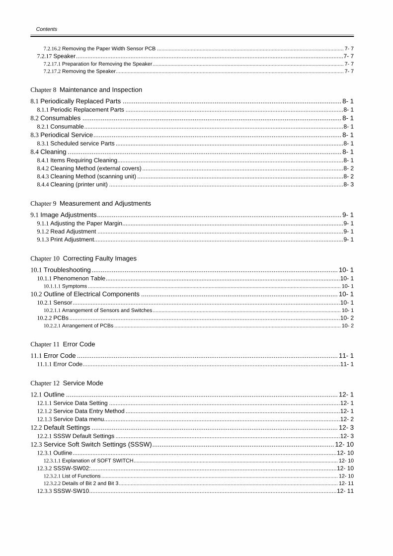
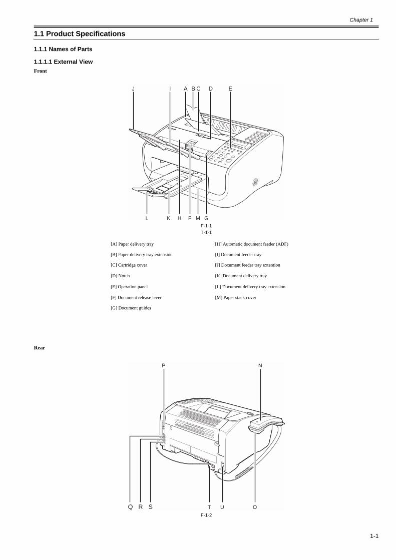
[A] Paper delivery tray [H] Automatic document feeder (ADF)
[B] Paper delivery tray extension [I] Document feeder tray
[C] Cartridge cover [J] Document feeder tray extention
[D] Notch [K] Document delivery tray
[E] Operation panel [L] Document delivery tray extension
[F] Document release lever [M] Paper stack cover
[G] Document guides
A BIJ C D E
F GMKL H
P N
OUTR SQ
Chapter 1
1-2
T-1-2
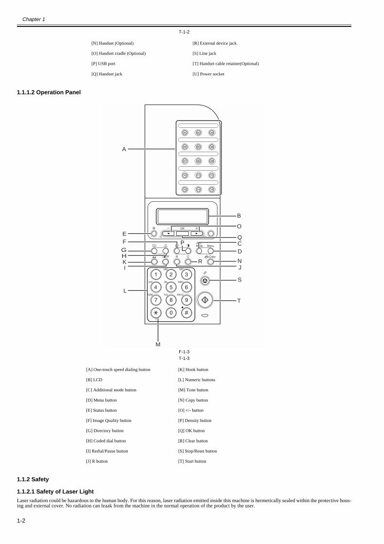
1.1.1.2 Operation Panel0018-4891
F-1-3T-1-3
1.1.2 Safety
1.1.2.1 Safety of Laser Light0018-4892
Laser radiation could be hazardous to the human body. For this reason, laser radiation emitted inside this machine is hermetically sealed within the protective hous-ing and external cover. No radiation can leaak from the machine in the normal operation of the product by the user.
[N] Handset (Optional) [R] External device jack
[O] Handset cradle (Optional) [S] Line jack
[P] USB port [T] Handset cable retainer(Optional)
[Q] Handset jack [U] Power socket
[A] One-touch speed dialing button [K] Hook button
[B] LCD [L] Numeric buttons
[C] Additional mode button [M] Tone button
[D] Menu button [N] Copy button
[E] Status button [O] +/- button
[F] Image Quality button [P] Density button
[G] Directory button [Q] OK button
[H] Coded dial button [R] Clear button
[I] Redial/Pause button [S] Stop/Reset button
[J] R button [T] Start button
M
R
P
A
HKI
G
E
L
F
S
T
Q
B
CD
JN
O
Chapter 1
1-3
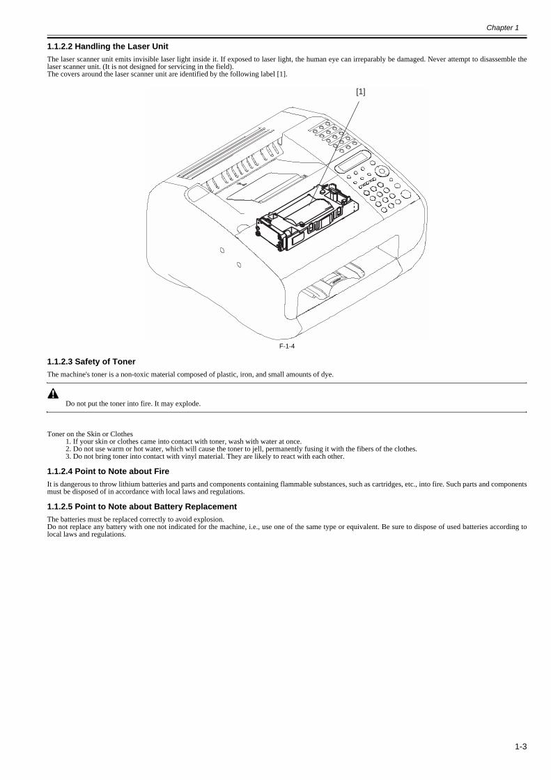
1.1.2.2 Handling the Laser Unit0018-4894
The laser scanner unit emits invisible laser light inside it. If exposed to laser light, the human eye can irreparably be damaged. Never attempt to disassemble thelaser scanner unit. (It is not designed for servicing in the field).The covers around the laser scanner unit are identified by the following label [1].
F-1-4
1.1.2.3 Safety of Toner0018-4895
The machine's toner is a non-toxic material composed of plastic, iron, and small amounts of dye.
Do not put the toner into fire. It may explode.
Toner on the Skin or Clothes1. If your skin or clothes came into contact with toner, wash with water at once.2. Do not use warm or hot water, which will cause the toner to jell, permanently fusing it with the fibers of the clothes.3. Do not bring toner into contact with vinyl material. They are likely to react with each other.
1.1.2.4 Point to Note about Fire0018-4896
It is dangerous to throw lithium batteries and parts and components containing flammable substances, such as cartridges, etc., into fire. Such parts and componentsmust be disposed of in accordance with local laws and regulations.
1.1.2.5 Point to Note about Battery Replacement0018-4897
The batteries must be replaced correctly to avoid explosion.Do not replace any battery with one not indicated for the machine, i.e., use one of the same type or equivalent. Be sure to dispose of used batteries according tolocal laws and regulations.
[1]
Chapter 1
1-4
1.1.3 Function List
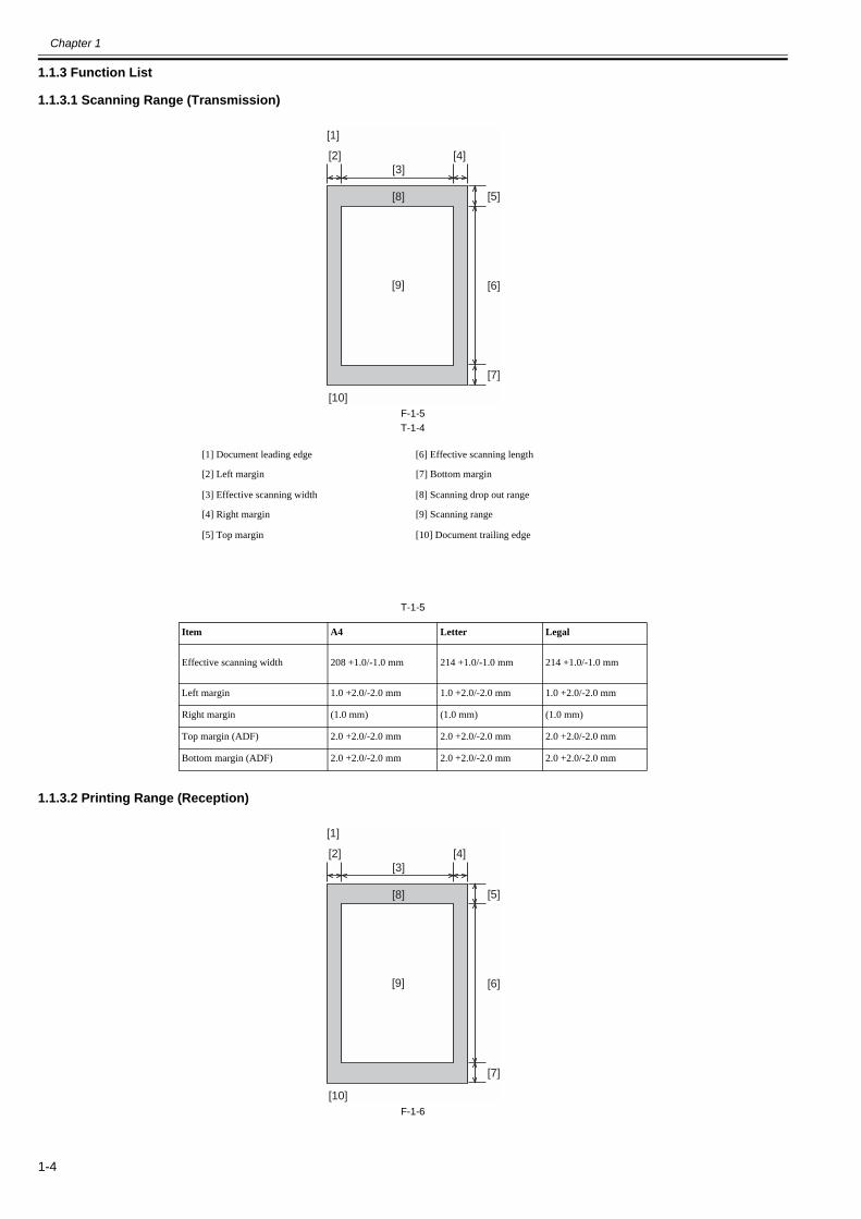
1.1.3.1 Scanning Range (Transmission)0018-4882
F-1-5T-1-4
T-1-5
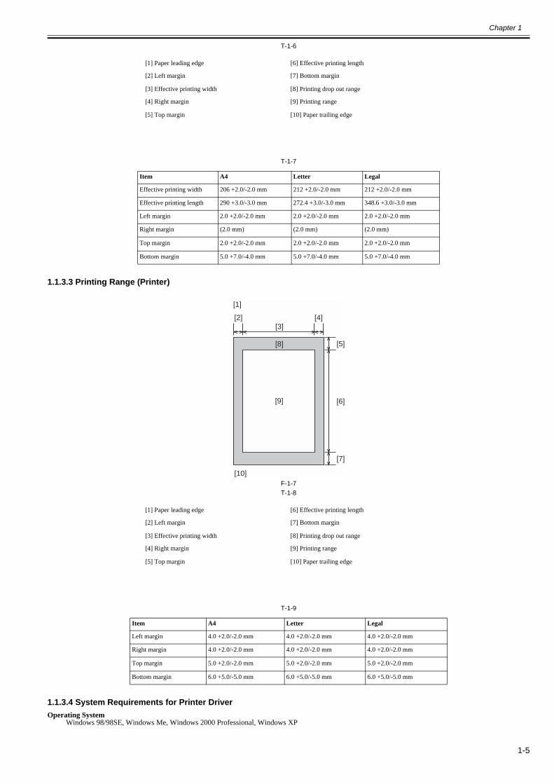
1.1.3.2 Printing Range (Reception)0018-4883
F-1-6
[1] Document leading edge [6] Effective scanning length
[2] Left margin [7] Bottom margin
[3] Effective scanning width [8] Scanning drop out range
[4] Right margin [9] Scanning range
[5] Top margin [10] Document trailing edge
Item A4 Letter Legal
Effective scanning width 208 +1.0/-1.0 mm 214 +1.0/-1.0 mm 214 +1.0/-1.0 mm
Left margin 1.0 +2.0/-2.0 mm 1.0 +2.0/-2.0 mm 1.0 +2.0/-2.0 mm
Right margin (1.0 mm) (1.0 mm) (1.0 mm)
Top margin (ADF) 2.0 +2.0/-2.0 mm 2.0 +2.0/-2.0 mm 2.0 +2.0/-2.0 mm
Bottom margin (ADF) 2.0 +2.0/-2.0 mm 2.0 +2.0/-2.0 mm 2.0 +2.0/-2.0 mm
[9]
[8]
[4][2]
[5]
[7]
[3]
[6]
[1]
[10]
[9]
[8]
[4][2]
[5]
[7]
[3]
[6]
[1]
[10]
Chapter 1
1-5
T-1-6
T-1-7
1.1.3.3 Printing Range (Printer)0018-4884
F-1-7T-1-8
T-1-9
1.1.3.4 System Requirements for Printer Driver0018-4885
Operating SystemWindows 98/98SE, Windows Me, Windows 2000 Professional, Windows XP
[1] Paper leading edge [6] Effective printing length
[2] Left margin [7] Bottom margin
[3] Effective printing width [8] Printing drop out range
[4] Right margin [9] Printing range
[5] Top margin [10] Paper trailing edge
Item A4 Letter Legal
Effective printing width 206 +2.0/-2.0 mm 212 +2.0/-2.0 mm 212 +2.0/-2.0 mm
Effective printing length 290 +3.0/-3.0 mm 272.4 +3.0/-3.0 mm 348.6 +3.0/-3.0 mm
Left margin 2.0 +2.0/-2.0 mm 2.0 +2.0/-2.0 mm 2.0 +2.0/-2.0 mm
Right margin (2.0 mm) (2.0 mm) (2.0 mm)
Top margin 2.0 +2.0/-2.0 mm 2.0 +2.0/-2.0 mm 2.0 +2.0/-2.0 mm
Bottom margin 5.0 +7.0/-4.0 mm 5.0 +7.0/-4.0 mm 5.0 +7.0/-4.0 mm
[1] Paper leading edge [6] Effective printing length
[2] Left margin [7] Bottom margin
[3] Effective printing width [8] Printing drop out range
[4] Right margin [9] Printing range
[5] Top margin [10] Paper trailing edge
Item A4 Letter Legal
Left margin 4.0 +2.0/-2.0 mm 4.0 +2.0/-2.0 mm 4.0 +2.0/-2.0 mm
Right margin 4.0 +2.0/-2.0 mm 4.0 +2.0/-2.0 mm 4.0 +2.0/-2.0 mm
Top margin 5.0 +2.0/-2.0 mm 5.0 +2.0/-2.0 mm 5.0 +2.0/-2.0 mm
Bottom margin 6.0 +5.0/-5.0 mm 6.0 +5.0/-5.0 mm 6.0 +5.0/-5.0 mm
[9]
[8]
[4][2]
[5]
[7]
[3]
[6]
[1]
[10]
Chapter 1
1-6
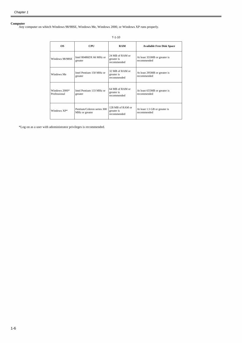
ComputerAny computer on whitch Windows 98/98SE, Windows Me, Windows 2000, or Windows XP runs properly.
T-1-10
*Log on as a user with adoministrator privileges is recommended.
OS CPU RAM Available Free Disk Space
Windows 98/98SE Intel 80486DX 66 MHz or greater
24 MB of RAM or greater is recommended
At least 355MB or greater is recommended
Windows Me Intel Pentium 150 MHz or greater
32 MB of RAM or greater is recommended
At least 295MB or greater is recommended
Windows 2000*Professional
Intel Pentium 133 MHz or greater
64 MB of RAM or greater is recommended
At least 655MB or greater is recommended
Windows XP* Pentium/Celeron series 300 MHz or greater
128 MB of RAM or greater is recommended
At least 1.5 GB or greater is recommended

Chapter 2 Document Feed and Exposure System

Contents
Contents
2.1 Overview/Configuration ................................................................................................................................................2-12.1.1 Overview...................................................................................................................................................................................... 2-1
2.2 Parts Replacement Procedure.........................................................................................................................................2-12.2.1 Separation Guide Unit.................................................................................................................................................................. 2-1
2.2.1.1 Preparation for Removing the Scraper ............................................................................................................................................................2-12.2.1.2 Removing the Scraper .....................................................................................................................................................................................2-1
2.2.2 Contact Sensor ............................................................................................................................................................................. 2-22.2.2.1 Preparation for Removing the Contact Sensor................................................................................................................................................2-22.2.2.2 Removing the Contact Sensor.........................................................................................................................................................................2-2
2.2.3 Separation Roller ......................................................................................................................................................................... 2-32.2.3.1 Preparation for Removing the Document Separation Roller ..........................................................................................................................2-32.2.3.2 Removing the Document Separation Roller ...................................................................................................................................................2-3
2.2.4 Feed Roller................................................................................................................................................................................... 2-42.2.4.1 Preparation for Removing the Document Feed Roller....................................................................................................................................2-42.2.4.2 Removing the Document Feed Roller.............................................................................................................................................................2-4
2.2.5 Reader Unit .................................................................................................................................................................................. 2-52.2.5.1 Preparation for Removing the Reader Unit.....................................................................................................................................................2-52.2.5.2 Removing the Reader Unit..............................................................................................................................................................................2-5
2.2.6 Document Feed Motor ................................................................................................................................................................. 2-52.2.6.1 Preparation for Removing the Document Feed Motor....................................................................................................................................2-52.2.6.2 Removing the Document Feed Motor.............................................................................................................................................................2-5
2.2.7 DS/DES Sensor ............................................................................................................................................................................ 2-52.2.7.1 Preparation for Removing the DS/DES Sensor ..............................................................................................................................................2-52.2.7.2 Removing the DS/DES Sensor........................................................................................................................................................................2-6

Chapter 2
2-1
2.1 Overview/Configuration
2.1.1 Overview0018-4898
F-2-1
T-2-1
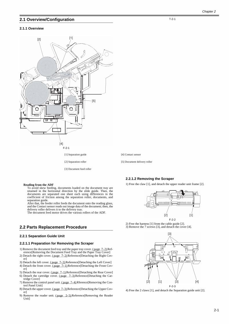
Reading from the ADFTo avoid skew feeding, documents loaded on the document tray areretained in the horizontal direction by the slide guide. Then, thedocuments are separated one sheet each using differences in thecoefficient of friction among the separation roller, documents, andseparation guide.After that, the feeder roller feeds the document onto the reading glass,and the Contact sensor reads out image data of the document; then, thedelivery roller delivers it to the delivery tray.The document feed motor drives the various rollers of the ADF.
2.2 Parts Replacement Procedure
2.2.1 Separation Guide Unit
2.2.1.1 Preparation for Removing the Scraper0018-4167
1) Remove the document feed tray and the paper tray cover. (page 7-2)Ref-erence[Removing the Document Feed Tray and the Paper Tray Cover]
2) Detach the right cover. (page 7-2)Reference[Detaching the Right Cov-er]
3) Detach the left cover. (page 7-2)Reference[Detaching the Left Cover]4) Detach the front cover. (page 7-1)Reference[Detaching the Front Cov-
er]5) Detach the rear cover. (page 7-1)Reference[Detaching the Rear Cover]6) Detach the cartridge cover. (page 7-3)Reference[Detaching the Car-
tridge Cover]7) Remove the control panel unit. (page 7-4)Rference[Removing the Con-
trol Panel Unit]8) Detach the upper cover. (page 7-3)Reference[Detaching the Upper Cov-
er]9) Remove the reader unit. (page 2-5)Reference[Removing the Reader
Unit]
2.2.1.2 Removing the Scraper0018-4168
1) Free the claw [1], and detach the upper reader unit frame [2].
F-2-22) Free the harness [1] from the cable guide [2].3) Remove the 7 screws [3], and detach the cover [4].
F-2-34) Free the 2 claws [1], and detach the Separation guide unit [2].
[1] Separation guide [4] Contact sensor
[2] Separation roller [5] Document delivery roller
[3] Document feed roller
[1][2]
[1][2] [3]
[3]
[4]
Chapter 2
2-2
F-2-4
2.2.2 Contact Sensor
2.2.2.1 Preparation for Removing the Contact Sensor0018-4169
1) Remove the document feed tray and the paper tray cover. (page 7-2)Ref-erence[Removing the Document Feed Tray and the Paper Tray Cover]
2) Detach the right cover. (page 7-2)Reference[Detaching the Right Cov-er]
3) Detach the left cover. (page 7-2)Reference[Detaching the Left Cover]4) Detach the front cover. (page 7-1)Reference[Detaching the Front Cov-
er]5) Detach the rear cover. (page 7-1)Reference[Detaching the Rear Cover]6) Detach the cartridge cover. (page 7-3)Reference[Detaching the Car-
tridge Cover]7) Remove the control panel unit. (page 7-4)Rference[Removing the Con-
trol Panel Unit]8) Detach the upper cover. (page 7-3)Reference[Detaching the Upper Cov-
er]9) Remove the reader unit. (page 2-5)Reference[Removing the Reader
Unit]
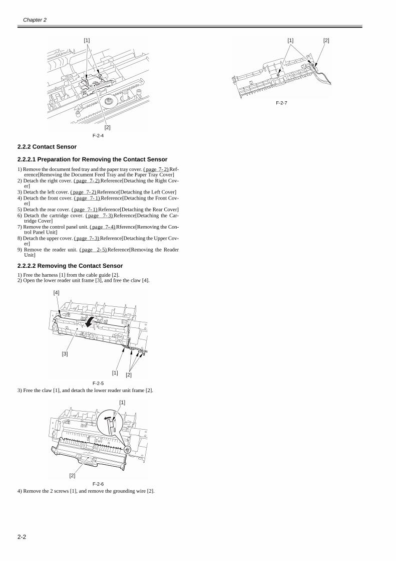
2.2.2.2 Removing the Contact Sensor0018-4170
1) Free the harness [1] from the cable guide [2].2) Open the lower reader unit frame [3], and free the claw [4].
F-2-53) Free the claw [1], and detach the lower reader unit frame [2].
F-2-64) Remove the 2 screws [1], and remove the grounding wire [2].
F-2-7
[1]
[2]
[1] [2]
[3]
[4]
[1]
[2]
[1] [2]
Chapter 2
2-3
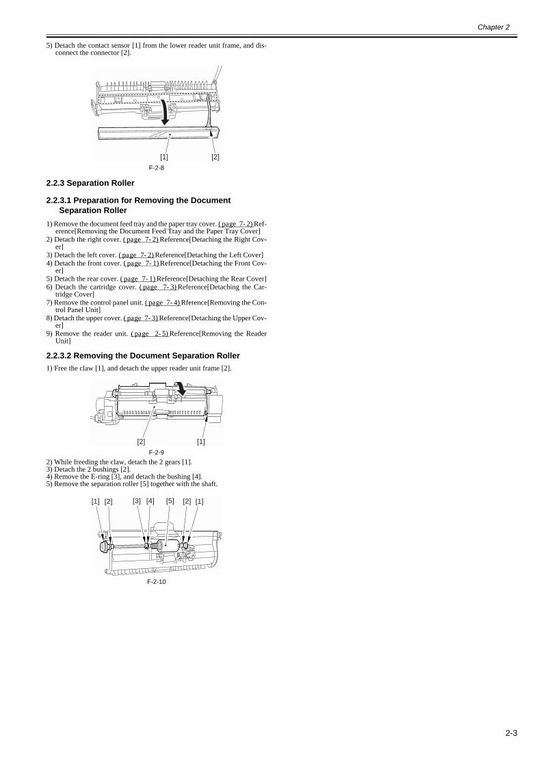
5) Detach the contact sensor [1] from the lower reader unit frame, and dis-connect the connector [2].
F-2-8
2.2.3 Separation Roller
2.2.3.1 Preparation for Removing the Document Separation Roller
0018-4171
1) Remove the document feed tray and the paper tray cover. (page 7-2)Ref-erence[Removing the Document Feed Tray and the Paper Tray Cover]
2) Detach the right cover. (page 7-2)Reference[Detaching the Right Cov-er]
3) Detach the left cover. (page 7-2)Reference[Detaching the Left Cover]4) Detach the front cover. (page 7-1)Reference[Detaching the Front Cov-
er]5) Detach the rear cover. (page 7-1)Reference[Detaching the Rear Cover]6) Detach the cartridge cover. (page 7-3)Reference[Detaching the Car-
tridge Cover]7) Remove the control panel unit. (page 7-4)Rference[Removing the Con-
trol Panel Unit]8) Detach the upper cover. (page 7-3)Reference[Detaching the Upper Cov-
er]9) Remove the reader unit. (page 2-5)Reference[Removing the Reader
Unit]
2.2.3.2 Removing the Document Separation Roller0018-4172
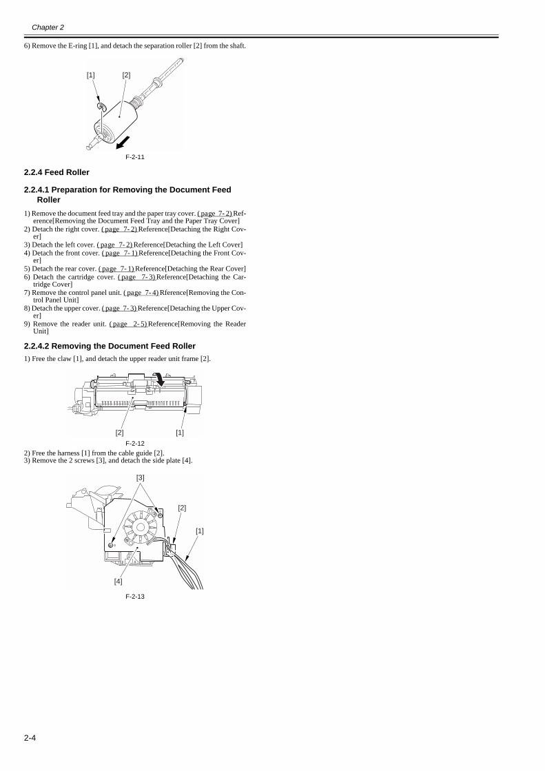
1) Free the claw [1], and detach the upper reader unit frame [2].
F-2-92) While freeding the claw, detach the 2 gears [1].3) Detach the 2 bushings [2].4) Remove the E-ring [3], and detach the bushing [4].5) Remove the separation roller [5] together with the shaft.
F-2-10
[1] [2]
[1][2]
[1] [1][2] [2][3] [4] [5]
Chapter 2
2-4
6) Remove the E-ring [1], and detach the separation roller [2] from the shaft.
F-2-11
2.2.4 Feed Roller
2.2.4.1 Preparation for Removing the Document Feed Roller
0018-4173
1) Remove the document feed tray and the paper tray cover. (page 7-2)Ref-erence[Removing the Document Feed Tray and the Paper Tray Cover]
2) Detach the right cover. (page 7-2)Reference[Detaching the Right Cov-er]
3) Detach the left cover. (page 7-2)Reference[Detaching the Left Cover]4) Detach the front cover. (page 7-1)Reference[Detaching the Front Cov-
er]5) Detach the rear cover. (page 7-1)Reference[Detaching the Rear Cover]6) Detach the cartridge cover. (page 7-3)Reference[Detaching the Car-
tridge Cover]7) Remove the control panel unit. (page 7-4)Rference[Removing the Con-
trol Panel Unit]8) Detach the upper cover. (page 7-3)Reference[Detaching the Upper Cov-
er]9) Remove the reader unit. (page 2-5)Reference[Removing the Reader
Unit]
2.2.4.2 Removing the Document Feed Roller0018-4174
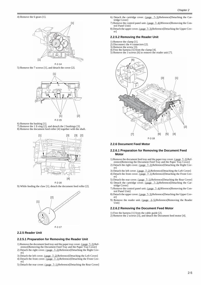
1) Free the claw [1], and detach the upper reader unit frame [2].
F-2-122) Free the harness [1] from the cable guide [2].3) Remove the 2 screws [3], and detach the side plate [4].
F-2-13
[1] [2]
[1][2]
[4]
[3]
[2]
[1]
Chapter 2
2-5
4) Remove the 6 gears [1].
F-2-145) Remove the 7 screws [1], and detach the cover [2].
F-2-156) Remove the bushing [1].7) Remove the 1 E-ring [2], and detach the 2 bushings [3].8) Remove the document feed roller [4] together with the shaft.
F-2-169) While feeding the claw [1], detach the document feed roller [2].
F-2-17
2.2.5 Reader Unit
2.2.5.1 Preparation for Removing the Reader Unit0018-3977
1) Remove the document feed tray and the paper tray cover. (page 7-2)Ref-erence[Removing the Document Feed Tray and the Paper Tray Cover]
2) Detach the right cover. (page 7-2)Reference[Detaching the Right Cov-er]
3) Detach the left cover. (page 7-2)Reference[Detaching the Left Cover]4) Detach the front cover. (page 7-1)Reference[Detaching the Front Cov-
er]5) Detach the rear cover. (page 7-1)Reference[Detaching the Rear Cover]
6) Detach the cartridge cover. (page 7-3)Reference[Detaching the Car-tridge Cover]
7) Remove the control panel unit. (page 7-4)Rference[Removing the Con-trol Panel Unit]
8) Detach the upper cover. (page 7-3)Reference[Detaching the Upper Cov-er]
2.2.5.2 Removing the Reader Unit0018-3975
1) Remove the clamp [1].2) Disconnect the 4 connectors [2].3) Remove the screw [3].4) Free the harness [5] from the clamp [4].5) Remove the 3 screws [6] to remove the reader unit [7].
F-2-18
2.2.6 Document Feed Motor
2.2.6.1 Preparation for Removing the Document Feed Motor
0018-4175
1) Remove the document feed tray and the paper tray cover. (page 7-2)Ref-erence[Removing the Document Feed Tray and the Paper Tray Cover]
2) Detach the right cover. (page 7-2)Reference[Detaching the Right Cov-er]
3) Detach the left cover. (page 7-2)Reference[Detaching the Left Cover]4) Detach the front cover. (page 7-1)Reference[Detaching the Front Cov-
er]5) Detach the rear cover. (page 7-1)Reference[Detaching the Rear Cover]6) Detach the cartridge cover. (page 7-3)Reference[Detaching the Car-
tridge Cover]7) Remove the control panel unit. (page 7-4)Rference[Removing the Con-
trol Panel Unit]8) Detach the upper cover. (page 7-3)Reference[Detaching the Upper Cov-
er]9) Remove the reader unit. (page 2-5)Reference[Removing the Reader
Unit]
2.2.6.2 Removing the Document Feed Motor0018-4176
1) Free the harness [1] from the cable guide [2].2) Remove the 2 screws [3], and detach the Document feed motor [4].
[1]
[1]
[1]
[1]
[2]
[1] [2][3] [3]
[4]
[1]
[2]
[2]
[6]
[6][7]
[3] [1]
[5] [4]
Chapter 2
2-6
F-2-19
2.2.7 DS/DES Sensor
2.2.7.1 Preparation for Removing the DS/DES Sensor0018-4177
1) Remove the document feed tray and the paper tray cover. (page 7-2)Ref-erence[Removing the Document Feed Tray and the Paper Tray Cover]
2) Detach the right cover. (page 7-2)Reference[Detaching the Right Cov-er]
3) Detach the left cover. (page 7-2)Reference[Detaching the Left Cover]4) Detach the front cover. (page 7-1)Reference[Detaching the Front Cov-
er]5) Detach the rear cover. (page 7-1)Reference[Detaching the Rear Cover]6) Detach the cartridge cover. (page 7-3)Reference[Detaching the Car-
tridge Cover]7) Remove the control panel unit. (page 7-4)Rference[Removing the Con-
trol Panel Unit]8) Detach the upper cover. (page 7-3)Reference[Detaching the Upper Cov-
er]9) Remove the reader unit. (page 2-5)Reference[Removing the Reader
Unit]
2.2.7.2 Removing the DS/DES Sensor0018-4178
1) Free the claw [1], and detach the upper reader unit frame [2].
F-2-202) Free the harness [1] from the cable guide [2].3) Remove the 2 screws [3], and detach the side plate [4].
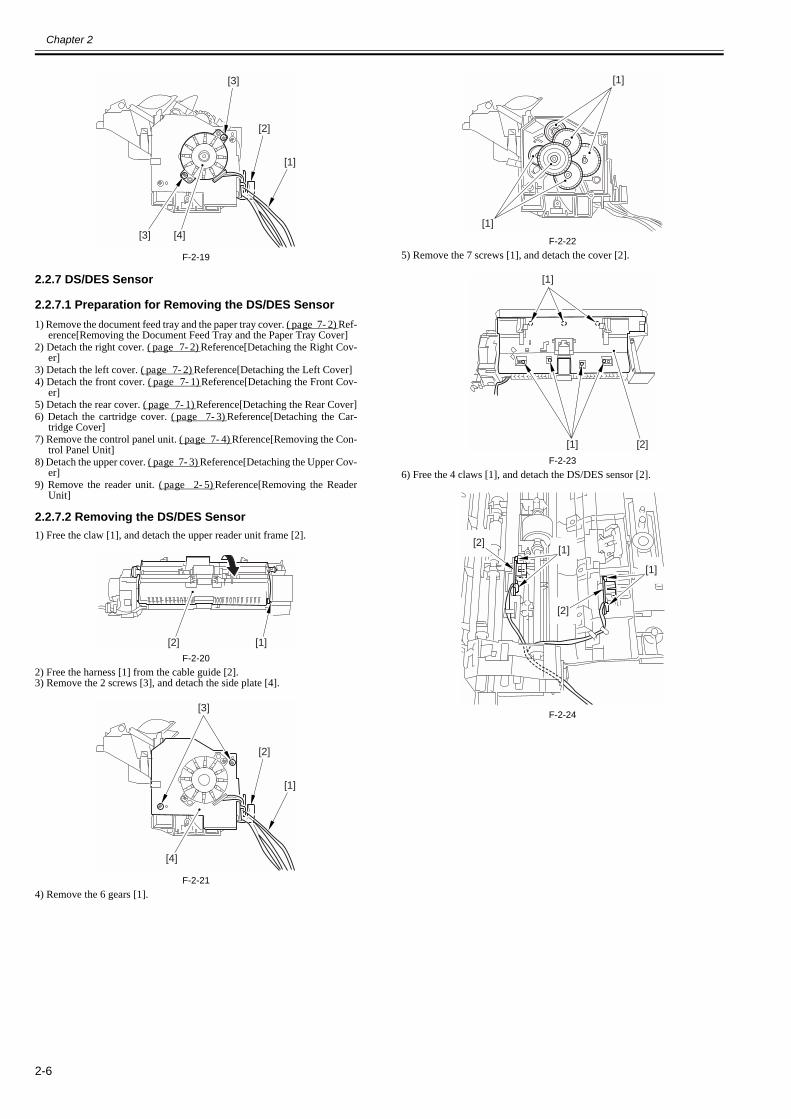
F-2-214) Remove the 6 gears [1].
F-2-225) Remove the 7 screws [1], and detach the cover [2].
F-2-236) Free the 4 claws [1], and detach the DS/DES sensor [2].
F-2-24
[4]
[2]
[1]
[3]
[3]
[1][2]
[4]
[3]
[2]
[1]
[1]
[1]
[1]
[1]
[2]
[1][2]
[1]
[2]

Chapter 3 Laser Exposure


Contents
Contents
3.1 Overview/Configuration ................................................................................................................................................3-13.1.1 Overview...................................................................................................................................................................................... 3-1
3.2 Parts Replacement Procedure.........................................................................................................................................3-13.2.1 Laser/Scanner Unit....................................................................................................................................................................... 3-1
3.2.1.1 Preparation for Removing the Laser/Scanner Unit .........................................................................................................................................3-13.2.1.2 Removing the Laser/Scanner Unit ..................................................................................................................................................................3-1

Chapter 3
3-1
3.1 Overview/Configuration
3.1.1 Overview0018-4899
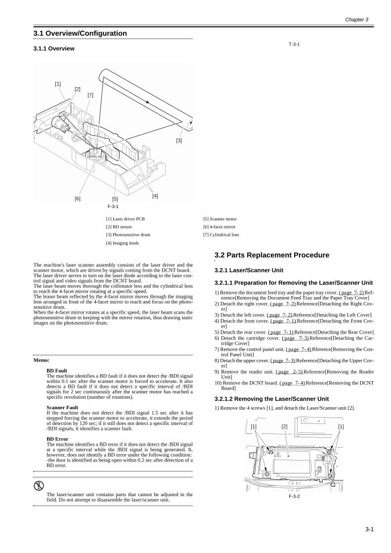
F-3-1
T-3-1
The machine's laser scanner assembly consists of the laser driver and thescanner motor, which are driven by signals coming from the DCNT board.The laser driver serves to turn on the laser diode according to the laser con-trol signal and video signals from the DCNT board.The laser beam moves thorough the collimator less and the cylindrical lensto reach the 4-facet mirror rotating at a specific speed.The leaser beam reflected by the 4-facet mirror moves through the imaginglens arranged in front of the 4-facet mirror to reach and focus on the photo-sensitive drum.When the 4-facet mirror rotates at a specific speed, the laser beam scans thephotosensitive drum in keeping with the mirror rotation, thus drawing staticimages on the photosensitive drum.
Memo:
BD FaultThe machine identifies a BD fault if it does not detect the /BDI signalwithin 0.1 sec after the scanner motor is forced to accelerate. It alsodetects a BD fault if it does not detect a specific interval of /BDIsignals for 2 sec continuously after the scanner motor has reached aspecific revolution (number of rotations).
Scanner FaultIf the machine does not detect the /BDI signal 1.5 sec after it hasstopped forcing the scanner motor to accelerate, it extends the periodof detection by 120 sec; if it still does not detect a specific interval of/BDI signals, it identifies a scanner fault.
BD ErrorThe machine identifies a BD error if it does not detect the /BDI signalat a specific interval while the /BDI signal is being generated. It,however, does not identify a BD error under the following condition:-the door is identified as being open within 0.2 sec after detection of aBD error.
The laser/scanner unit contains parts that cannot be adjusted in thefield. Do not attempt to disassemble the laser/scanner unit.
3.2 Parts Replacement Procedure
3.2.1 Laser/Scanner Unit
3.2.1.1 Preparation for Removing the Laser/Scanner Unit0018-4182
1) Remove the document feed tray and the paper tray cover. (page 7-2)Ref-erence[Removing the Document Feed Tray and the Paper Tray Cover]
2) Detach the right cover. (page 7-2)Reference[Detaching the Right Cov-er]
3) Detach the left cover. (page 7-2)Reference[Detaching the Left Cover]4) Detach the front cover. (page 7-1)Reference[Detaching the Front Cov-
er]5) Detach the rear cover. (page 7-1)Reference[Detaching the Rear Cover]6) Detach the cartridge cover. (page 7-3)Reference[Detaching the Car-
tridge Cover]7) Remove the control panel unit. (page 7-4)Rference[Removing the Con-
trol Panel Unit]8) Detach the upper cover. (page 7-3)Reference[Detaching the Upper Cov-
er]9) Remove the reader unit. (page 2-5)Reference[Removing the Reader
Unit]10) Remove the DCNT board. (page 7-4)Reference[Removing the DCNT
Board]
3.2.1.2 Removing the Laser/Scanner Unit0018-4183
1) Remove the 4 screws [1], and detach the Laser/Scanner unit [2].
F-3-2
[1]
[4][5][6]
[7][2]
[3]
[1] Laser driver PCB [5] Scanner motor
[2] BD sensor [6] 4-facet mirror
[3] Photosensitive drum [7] Cylindrical lens
[4] Imaging lends
[1][1] [2]


Chapter 4 Image Formation


Contents
Contents
4.1 Overview/Configuration ................................................................................................................................................4-14.1.1 Overview...................................................................................................................................................................................... 4-1
4.2 Toner Cartridge ..............................................................................................................................................................4-14.2.1 Display the message.................................................................................................................................................................... 4-1
4.3 Parts Replacement Procedure.........................................................................................................................................4-14.3.1 Transfer Charging Roller ............................................................................................................................................................. 4-1
4.3.1.1 Removing the Transfer Charging Roller.........................................................................................................................................................4-1

Chapter 4
4-1
4.1 Overview/Configuration
4.1.1 Overview0018-4900
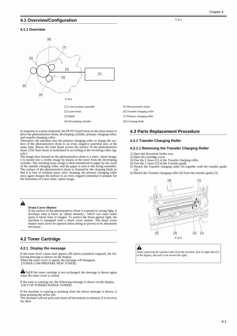
F-4-1
T-4-1
In response to a print command, the DCNT board turns on the main motor todrive the photosensitive drum, developing cylinder, primary charging roller,and transfer charging roller.Thereafter, the machine uses the primary charging roller to charge the sur-face of the photosensitive drum to an even, negative potential and, at thesame time, directs the laser beam across the surface of the photosensitivedrum. (The laser beam is modulated to according to the incoming video sig-nals.)The image thus formed on the photosensitive drum is a static, latent image;it is turned into a visible image by means of the toner from the developingcylinder. The resulting toner image is then transferred to paper by the workof the transfer charging roller, and the paper is sent to the fixing assembly.The surface of the photosensitive drum is cleaned by the cleaning blade sothat it is free of residual toner; after cleaning, the primary charging rolleronce again charges the surface to an even, negative potential to prepare forthe formation of a new static, latent image.
Drum Cover ShutterIf the surface of the photosensitive drum is exposed to strong light, itdevelops what is know as "photo memory," which can cause whitespots or black lines in images. To protect the drum against light, themachine is equipped with a drum cover shutter. The drum covershutter must never be opened unless doing so proves to be absolutelynecessary.
4.2 Toner Cartridge
4.2.1 Display the message0018-5781
If the toner level comes near approx.100 sheets (standard original), the fol-lowing message is shown on the display.When the toner cover is opend, the message will disappear. [TONER LOW/PREPARE NEW TONER]
Å@If the toner cartridge is not exchanged, the message is shown againwhen the toner cover is closed.
If the toner is running out, the following message is shown on the display. [OUT OF TONER/CHANGE TONER]
If the machine is copying or printing when the above message is shown, itkeep printing the active job.The machine will not print and stores all documents in memory if it receivesfax data/
4.3 Parts Replacement Procedure
4.3.1 Transfer Charging Roller
4.3.1.1 Removing the Transfer Charging Roller0018-4184
1) Open the document feeder tray.2) Open the cartridge cover.3) Free the 2 claws [1] of the Transfer charging roller.4) Free the 2 claws [2] of the Transfer guide.5) Detach the Transfer charging roller [4] together with the transfer guide
[3].6) Detach the Transfer charging roller [4] from the transfer guide [3].
F-4-2
[1]
[4]
[5]
[6]
[7]
[8]
[2]
[3]
[1] Laser/scanner assembly [5] Photosensitive drum
[2] Laser beam [6] Transfer charging roller
[3] Blade [7] Primary charging roller
[4] Developing cylinder [8] Cleaning blade
When removing the transfer roller from the machine, free its right side ([1] in the figure), and pull it out toward the right.
[1]
[1][2][2] [3]
[4]


Chapter 5 Pickup and Feed System

Contents
Contents
5.1 Overview/Configuration ................................................................................................................................................5-15.1.1 Overview...................................................................................................................................................................................... 5-1
5.2 Detection Jams ...............................................................................................................................................................5-15.2.1 Jam Detection Outline.................................................................................................................................................................. 5-1
5.2.1.1 Type of Jams ...................................................................................................................................................................................................5-15.2.2 Delay Jams ................................................................................................................................................................................... 5-2
5.2.2.1 Pickup Delay Jam............................................................................................................................................................................................5-25.2.2.2 Delivery Delay Jam.........................................................................................................................................................................................5-2
5.2.3 Stationary Jams ............................................................................................................................................................................ 5-25.2.3.1 Pickup Stationary Jam.....................................................................................................................................................................................5-25.2.3.2 Delivery Stationary Jam..................................................................................................................................................................................5-2
5.2.4 Other Jams ................................................................................................................................................................................... 5-25.2.4.1 Fixing Wrap Jam .............................................................................................................................................................................................5-25.2.4.2 Initial Jam........................................................................................................................................................................................................5-25.2.4.3 Cover Open Jam..............................................................................................................................................................................................5-2
5.3 Parts Replacement Procedure.........................................................................................................................................5-25.3.1 Pickup Unit .................................................................................................................................................................................. 5-2
5.3.1.1 Preparation for Removing the Paper Pickup Unit...........................................................................................................................................5-25.3.1.2 Removing the Paper Pickup Unit ....................................................................................................................................................................5-2
5.3.2 Cassette Pickup Roller ................................................................................................................................................................. 5-35.3.2.1 Removing the Cassette Pickup Roller.............................................................................................................................................................5-3
5.3.3 Cassette Pickup Solenoid ............................................................................................................................................................. 5-35.3.3.1 Preparation for Removing the Cassette Pickup Solenoid ...............................................................................................................................5-35.3.3.2 Removing the Cassette Pickup Solenoid.........................................................................................................................................................5-3
5.3.4 Cassette Separation Pad ............................................................................................................................................................... 5-35.3.4.1 Removing the Cassette Separation Pad...........................................................................................................................................................5-3
5.3.5 Main Motor .................................................................................................................................................................................. 5-45.3.5.1 Preparation for Removing the Main Motor.....................................................................................................................................................5-45.3.5.2 Removing the Main Motor..............................................................................................................................................................................5-4

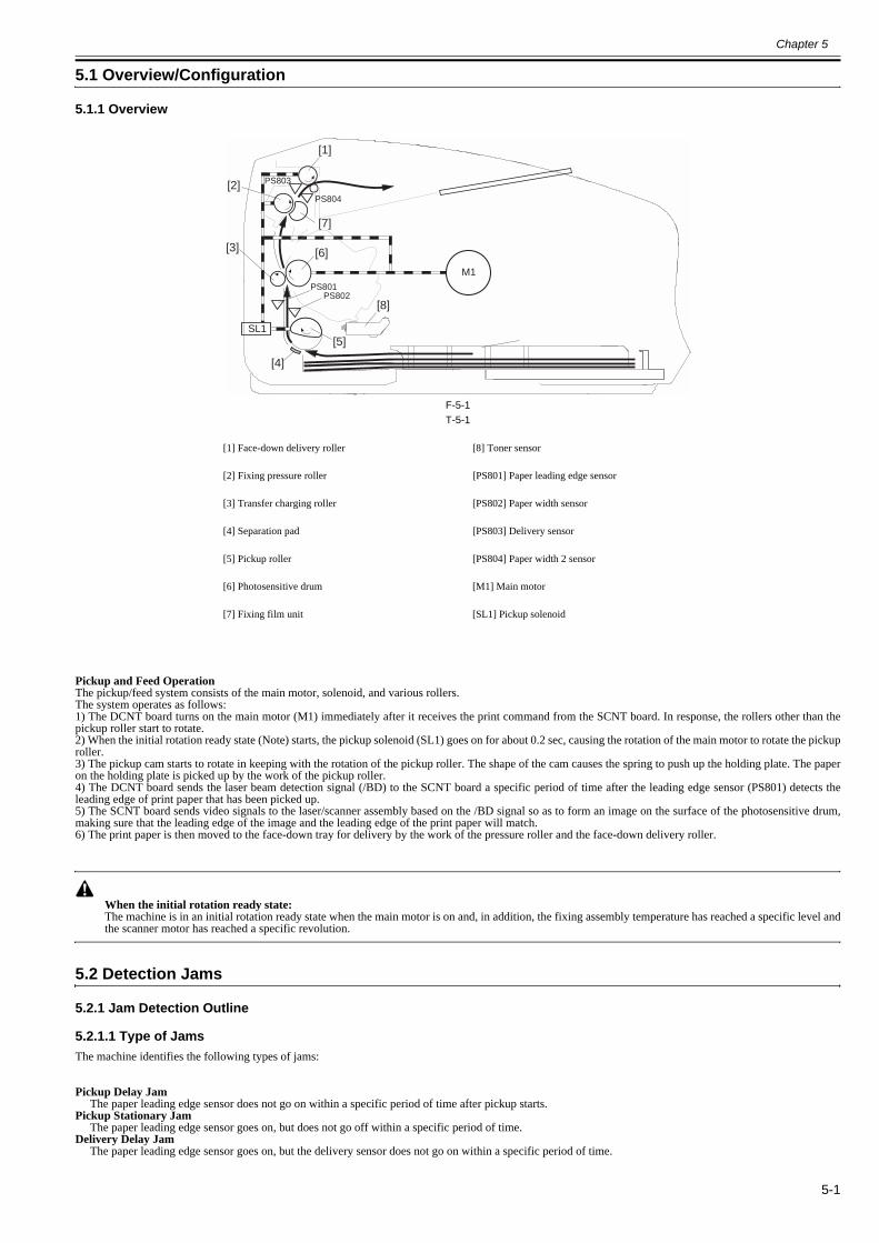
Chapter 5
5-1
5.1 Overview/Configuration
5.1.1 Overview0018-4902
F-5-1T-5-1
Pickup and Feed OperationThe pickup/feed system consists of the main motor, solenoid, and various rollers.The system operates as follows:1) The DCNT board turns on the main motor (M1) immediately after it receives the print command from the SCNT board. In response, the rollers other than thepickup roller start to rotate.2) When the initial rotation ready state (Note) starts, the pickup solenoid (SL1) goes on for about 0.2 sec, causing the rotation of the main motor to rotate the pickuproller.3) The pickup cam starts to rotate in keeping with the rotation of the pickup roller. The shape of the cam causes the spring to push up the holding plate. The paperon the holding plate is picked up by the work of the pickup roller.4) The DCNT board sends the laser beam detection signal (/BD) to the SCNT board a specific period of time after the leading edge sensor (PS801) detects theleading edge of print paper that has been picked up.5) The SCNT board sends video signals to the laser/scanner assembly based on the /BD signal so as to form an image on the surface of the photosensitive drum,making sure that the leading edge of the image and the leading edge of the print paper will match.6) The print paper is then moved to the face-down tray for delivery by the work of the pressure roller and the face-down delivery roller.
When the initial rotation ready state:The machine is in an initial rotation ready state when the main motor is on and, in addition, the fixing assembly temperature has reached a specific level andthe scanner motor has reached a specific revolution.
5.2 Detection Jams
5.2.1 Jam Detection Outline
5.2.1.1 Type of Jams0018-4903
The machine identifies the following types of jams:
Pickup Delay JamThe paper leading edge sensor does not go on within a specific period of time after pickup starts.
Pickup Stationary JamThe paper leading edge sensor goes on, but does not go off within a specific period of time.
Delivery Delay JamThe paper leading edge sensor goes on, but the delivery sensor does not go on within a specific period of time.
[1] Face-down delivery roller [8] Toner sensor
[2] Fixing pressure roller [PS801] Paper leading edge sensor
[3] Transfer charging roller [PS802] Paper width sensor
[4] Separation pad [PS803] Delivery sensor
[5] Pickup roller [PS804] Paper width 2 sensor
[6] Photosensitive drum [M1] Main motor
[7] Fixing film unit [SL1] Pickup solenoid
PS801PS802
[1]
[2]
[3]
[4]
[5]
[6]
[8]
[7]
PS803
SL1
M1
PS804
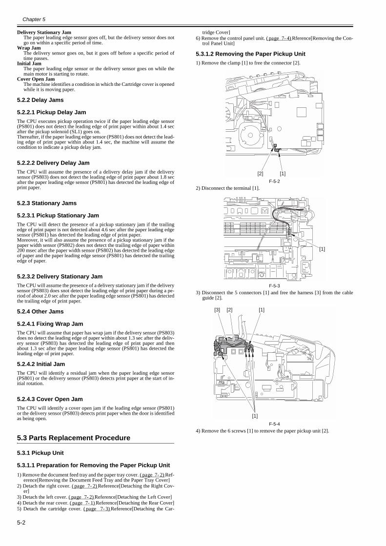
Chapter 5
5-2
Delivery Stationary JamThe paper leading edge sensor goes off, but the delivery sensor does notgo on within a specific period of time.
Wrap JamThe delivery sensor goes on, but it goes off before a specific period oftime passes.
Initial JamThe paper leading edge sensor or the delivery sensor goes on while themain motor is starting to rotate.
Cover Open JamThe machine identifies a condition in which the Cartridge cover is openedwhile it is moving paper.
5.2.2 Delay Jams
5.2.2.1 Pickup Delay Jam0018-4904
The CPU executes pickup operation twice if the paper leading edge sensor(PS801) does not detect the leading edge of print paper within about 1.4 secafter the pickup solenoid (SL1) goes on.Thereafter, if the paper leading edge sensor (PS801) does not detect the lead-ing edge of print paper within about 1.4 sec, the machine will assume thecondition to indicate a pickup delay jam.
5.2.2.2 Delivery Delay Jam0018-4905
The CPU will assume the presence of a delivery delay jam if the deliverysensor (PS803) does not detect the leading edge of print paper about 1.8 secafter the paper leading edge sensor (PS801) has detected the leading edge ofprint paper.
5.2.3 Stationary Jams
5.2.3.1 Pickup Stationary Jam0018-4906
The CPU will detect the presence of a pickup stationary jam if the trailingedge of print paper is not detected about 4.6 sec after the paper leading edgesensor (PS801) has detected the leading edge of print paper.Moreover, it will also assume the presence of a pickup stationary jam if thepaper width sensor (PS802) does not detect the trailing edge of paper within200 msec after the paper width sensor (PS802) has detected the leading edgeof paper and the paper leading edge sensor (PS801) has detected the trailingedge of paper.
5.2.3.2 Delivery Stationary Jam0018-4907
The CPU will assume the presence of a delivery stationary jam if the deliverysensor (PS803) does snot detect the leading edge of print paper during a pe-riod of about 2.0 sec after the paper leading edge sensor (PS801) has detectedthe trailing edge of print paper.
5.2.4 Other Jams
5.2.4.1 Fixing Wrap Jam0018-4908
The CPU will assume that paper has wrap jam if the delivery sensor (PS803)does no detect the leading edge of paper within about 1.3 sec after the deliv-ery sensor (PS803) has detected the leading edge of print paper and thenabout 1.3 sec after the paper leading edge sensor (PS801) has detected theleading edge of print paper.
5.2.4.2 Initial Jam0018-4909
The CPU will identify a residual jam when the paper leading edge sensor(PS801) or the delivery sensor (PS803) detects print paper at the start of in-itial rotation.
5.2.4.3 Cover Open Jam0018-4910
The CPU will identify a cover open jam if the leading edge sensor (PS801)or the delivery sensor (PS803) detects print paper when the door is identifiedas being open.
5.3 Parts Replacement Procedure
5.3.1 Pickup Unit
5.3.1.1 Preparation for Removing the Paper Pickup Unit0018-4185
1) Remove the document feed tray and the paper tray cover. (page 7-2)Ref-erence[Removing the Document Feed Tray and the Paper Tray Cover]
2) Detach the right cover. (page 7-2)Reference[Detaching the Right Cov-er]
3) Detach the left cover. (page 7-2)Reference[Detaching the Left Cover]4) Detach the rear cover. (page 7-1)Reference[Detaching the Rear Cover]5) Detach the cartridge cover. (page 7-3)Reference[Detaching the Car-
tridge Cover]6) Remove the control panel unit. (page 7-4)Rference[Removing the Con-
trol Panel Unit]
5.3.1.2 Removing the Paper Pickup Unit0018-4186
1) Remove the clamp [1] to free the connector [2].
F-5-22) Disconnect the terminal [1].
F-5-33) Disconnect the 5 connectors [1] and free the harness [3] from the cable
guide [2].
F-5-44) Remove the 6 screws [1] to remove the paper pickup unit [2].
[2] [1]
[1]
[3]
[1]
[2] [1]
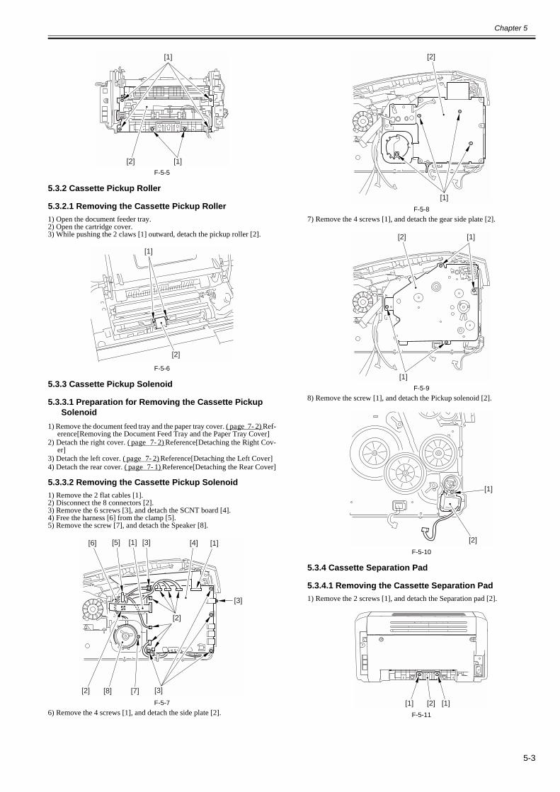
Chapter 5
5-3
F-5-5
5.3.2 Cassette Pickup Roller
5.3.2.1 Removing the Cassette Pickup Roller0018-4187
1) Open the document feeder tray.2) Open the cartridge cover.3) While pushing the 2 claws [1] outward, detach the pickup roller [2].
F-5-6
5.3.3 Cassette Pickup Solenoid
5.3.3.1 Preparation for Removing the Cassette Pickup Solenoid
0018-4188
1) Remove the document feed tray and the paper tray cover. (page 7-2)Ref-erence[Removing the Document Feed Tray and the Paper Tray Cover]
2) Detach the right cover. (page 7-2)Reference[Detaching the Right Cov-er]
3) Detach the left cover. (page 7-2)Reference[Detaching the Left Cover]4) Detach the rear cover. (page 7-1)Reference[Detaching the Rear Cover]
5.3.3.2 Removing the Cassette Pickup Solenoid0018-4189
1) Remove the 2 flat cables [1].2) Disconnect the 8 connectors [2].3) Remove the 6 screws [3], and detach the SCNT board [4].4) Free the harness [6] from the clamp [5].5) Remove the screw [7], and detach the Speaker [8].
F-5-76) Remove the 4 screws [1], and detach the side plate [2].
F-5-87) Remove the 4 screws [1], and detach the gear side plate [2].
F-5-98) Remove the screw [1], and detach the Pickup solenoid [2].
F-5-10
5.3.4 Cassette Separation Pad
5.3.4.1 Removing the Cassette Separation Pad0018-4191
1) Remove the 2 screws [1], and detach the Separation pad [2].
F-5-11
[1]
[1][2]
[1]
[2]
[1] [1]
[2]
[2]
[3]
[3]
[5][6]
[7][8]
[4]
[3]
[1]
[2]
[1]
[1][2]
[1]
[2]
[1] [1][2]
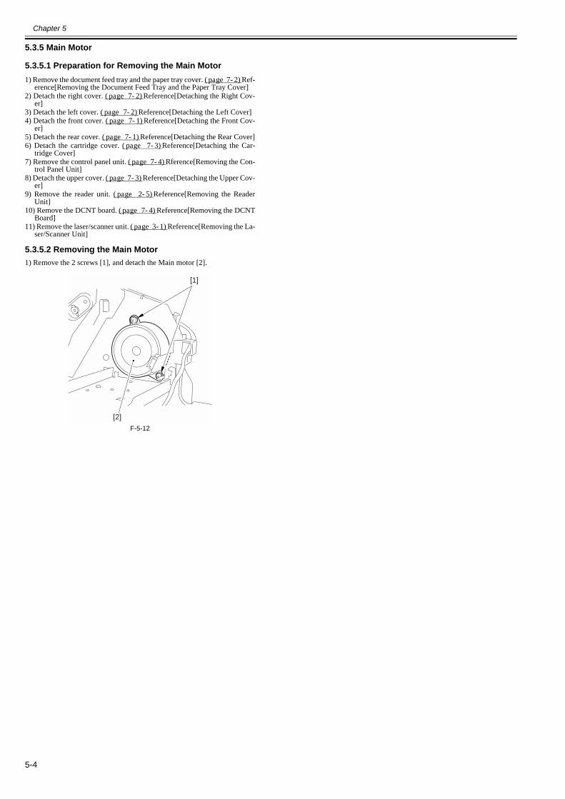
Chapter 5
5-4
5.3.5 Main Motor
5.3.5.1 Preparation for Removing the Main Motor0018-4192
1) Remove the document feed tray and the paper tray cover. (page 7-2)Ref-erence[Removing the Document Feed Tray and the Paper Tray Cover]
2) Detach the right cover. (page 7-2)Reference[Detaching the Right Cov-er]
3) Detach the left cover. (page 7-2)Reference[Detaching the Left Cover]4) Detach the front cover. (page 7-1)Reference[Detaching the Front Cov-
er]5) Detach the rear cover. (page 7-1)Reference[Detaching the Rear Cover]6) Detach the cartridge cover. (page 7-3)Reference[Detaching the Car-
tridge Cover]7) Remove the control panel unit. (page 7-4)Rference[Removing the Con-
trol Panel Unit]8) Detach the upper cover. (page 7-3)Reference[Detaching the Upper Cov-
er]9) Remove the reader unit. (page 2-5)Reference[Removing the Reader
Unit]10) Remove the DCNT board. (page 7-4)Reference[Removing the DCNT
Board]11) Remove the laser/scanner unit. (page 3-1)Reference[Removing the La-
ser/Scanner Unit]
5.3.5.2 Removing the Main Motor0018-4194
1) Remove the 2 screws [1], and detach the Main motor [2].
F-5-12
[1]
[2]

Chapter 6 Fixing System

Contents
Contents
6.1 Overview/Configuration ................................................................................................................................................6-16.1.1 Overview...................................................................................................................................................................................... 6-1
6.2 Various Control Mechanisms.........................................................................................................................................6-16.2.1 Controlling the Temperature of the Fixing Unit .......................................................................................................................... 6-1
6.2.1.1 Heater Temperature Control ...........................................................................................................................................................................6-16.3 Protection Function ........................................................................................................................................................6-3
6.3.1 Protective Mechanisms ................................................................................................................................................................ 6-36.3.2 Detection of a Fault...................................................................................................................................................................... 6-3
6.4 Parts Replacement Procedure.........................................................................................................................................6-36.4.1 Fixing Unit ................................................................................................................................................................................... 6-3
6.4.1.1 Preparation for Removing the Fixing Unit......................................................................................................................................................6-36.4.1.2 Removing the Fixing Unit...............................................................................................................................................................................6-3
6.4.2 Fixing Film Unit .......................................................................................................................................................................... 6-36.4.2.1 Preparation for Removing the Fixing Film Unit .............................................................................................................................................6-36.4.2.2 Removing the Fixing Film Unit ......................................................................................................................................................................6-3
6.4.3 Fixing Pressure Roller.................................................................................................................................................................. 6-46.4.3.1 Preparation for Removing the Fixing Pressure Roller ....................................................................................................................................6-46.4.3.2 Removing the Fixing Pressure Roller .............................................................................................................................................................6-4

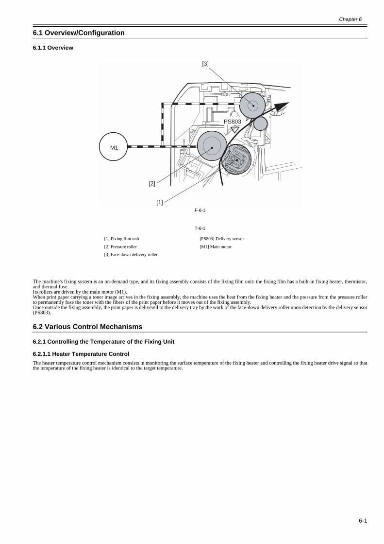
Chapter 6
6-1
6.1 Overview/Configuration
6.1.1 Overview0018-4912
F-6-1
T-6-1
The machine's fixing system is an on-demand type, and its fixing assembly consists of the fixing film unit: the fixing film has a built-in fixing heater, thermistor,and thermal fuse.Its rollers are driven by the main motor (M1).When print paper carrying a toner image arrives in the fixing assembly, the machine uses the heat from the fixing heater and the pressure from the pressure rollerto permanently fuse the toner with the fibers of the print paper before it moves out of the fixing assembly.Once outside the fixing assembly, the print paper is delivered to the delivery tray by the work of the face-down delivery roller upon detection by the delivery sensor(PS803).
6.2 Various Control Mechanisms
6.2.1 Controlling the Temperature of the Fixing Unit
6.2.1.1 Heater Temperature Control0018-4914
The heater temperature control mechanism consists in monitoring the surface temperature of the fixing heater and controlling the fixing heater drive signal so thatthe temperature of the fixing heater is identical to the target temperature.
[1] Fixing film unit [PS803] Delivery sensor
[2] Pressure roller [M1] Main motor
[3] Face-down delivery roller
M1
PS803
[1]
[2]
[3]
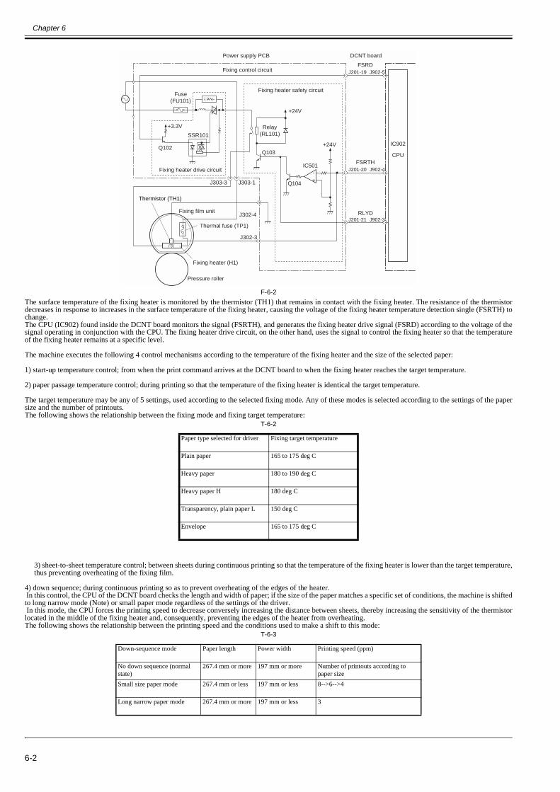
Chapter 6
6-2
F-6-2The surface temperature of the fixing heater is monitored by the thermistor (TH1) that remains in contact with the fixing heater. The resistance of the thermistordecreases in response to increases in the surface temperature of the fixing heater, causing the voltage of the fixing heater temperature detection single (FSRTH) tochange.The CPU (IC902) found inside the DCNT board monitors the signal (FSRTH), and generates the fixing heater drive signal (FSRD) according to the voltage of thesignal operating in conjunction with the CPU. The fixing heater drive circuit, on the other hand, uses the signal to control the fixing heater so that the temperatureof the fixing heater remains at a specific level.
The machine executes the following 4 control mechanisms according to the temperature of the fixing heater and the size of the selected paper:
1) start-up temperature control; from when the print command arrives at the DCNT board to when the fixing heater reaches the target temperature.
2) paper passage temperature control; during printing so that the temperature of the fixing heater is identical the target temperature.
The target temperature may be any of 5 settings, used according to the selected fixing mode. Any of these modes is selected according to the settings of the papersize and the number of printouts.The following shows the relationship between the fixing mode and fixing target temperature:
T-6-2
3) sheet-to-sheet temperature control; between sheets during continuous printing so that the temperature of the fixing heater is lower than the target temperature,thus preventing overheating of the fixing film.
4) down sequence; during continuous printing so as to prevent overheating of the edges of the heater. In this control, the CPU of the DCNT board checks the length and width of paper; if the size of the paper matches a specific set of conditions, the machine is shiftedto long narrow mode (Note) or small paper mode regardless of the settings of the driver. In this mode, the CPU forces the printing speed to decrease conversely increasing the distance between sheets, thereby increasing the sensitivity of the thermistorlocated in the middle of the fixing heater and, consequently, preventing the edges of the heater from overheating.The following shows the relationship between the printing speed and the conditions used to make a shift to this mode:
T-6-3
Paper type selected for driver Fixing target temperature
Plain paper 165 to 175 deg C
Heavy paper 180 to 190 deg C
Heavy paper H 180 deg C
Transparency, plain paper L 150 deg C
Envelope 165 to 175 deg C
Down-sequence mode Paper length Power width Printing speed (ppm)
No down sequence (normal state)
267.4 mm or more 197 mm or more Number of printouts according to paper size
Small size paper mode 267.4 mm or less 197 mm or less 8-->6-->4
Long narrow paper mode 267.4 mm or more 197 mm or less 3
+-
Thermal fuse (TP1)
J302-4
J302-3
J303-1
Fixing film unit
J303-3
+3.3V
SSR101
Q102
Fuse (FU101)
Power supply PCB
IC902
CPU
DCNT board
Thermistor (TH1)
Q103
Relay(RL101)
+24V
FSRD
+24V
IC501
J201-19 J902-5
RLYDJ201-21 J902-3
FSRTHJ201-20 J902-4
Fixing control circuit
Fixing heater safety circuit
Fixing heater (H1)
Q104
Pressure roller
Fixing heater drive circuit
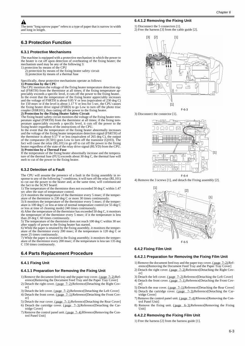
Chapter 6
6-3
The term "long narrow paper" refers to a type of paper that is narrow in widthand long in length.
6.3 Protection Function
6.3.1 Protective Mechanisms0018-4915
The machine is equipped with a protective mechanism in which the power tothe heater is cut off upon detection of overheating of the fixing heater; themechanism used may be any of the following 3:1) protection by means of the CPU
2) protection by means of the fixing heater safety circuit3) protection by means of a thermal fuse
Specifically, these protective mechanisms operate as follows:1) Protection by the CPUThe CPU monitors the voltage of the fixing heater temperature detection sig-nal (FSRTH) from the thermistor at all times; if the fixing temperature ap-preciably exceeds a specific level, it cuts off the power to the fixing heater.In the event that the temperature of the fixing heater appreciably increasesand the voltage of FSRTH is about 0.85 V or less (equivalent of 230 deg C)for 150 msec or if the level is about 1.17 V or less for 5 sec, the CPU causesthe fixing heater drive signal (FSRD) to go Low to turn off the photo triaccoupler (SSR101), thus cutting off the power to the fixing heater.2) Protection by the Fixing Heater Safety CircuitThe fixing heater safety circuit monitors the voltage of the fixing heater tem-perature signal (FSRTH) from the thermistor at all times; if the fixing tem-perature appreciably exceeds a specific level, it cuts off the power to thefixing heater regardless of the instructions of the CPU.In the event that the temperature of the fixing heater abnormally increasesand the voltage of the fixing heater temperature detection signal (FSRTH) ofthe thermistor is about 0.57 V or less (equivalent of 265 deg C), the outputof the comparator (IC501) goes Low to turn off the transistor (Q103). Thefact will cause the relay (RL101) to go off to cut off the power to the fixingheater regardless of the state of the relay drive signal (RLYD) from the CPU.3) Protection by a Thermal FuseIf the temperature of the fixing heater abnormally increase and the tempera-ture of the thermal fuse (FU1) exceeds about 30 deg C, the thermal fuse willmelt to cut of the power to the fixing heater.
6.3.2 Detection of a Fault0018-4916
The CPU will assume the presence of a fault in the fixing assembly in re-sponse to any of the following 7 conditions; it will turn off the relay (RL101)to cut out the power to the heater and, at the same time, will communicatethe fact to the SCNT board:1) The temperature of the thermistor does not exceeded 50 deg C within 1.47sec after the start of temperature control.2) It monitors the temperature of the thermistor every 5 msec; if the temper-ature of the thermistor is 230 deg C or more 30 times continuously.3) It monitors the temperature of the thermistor every 5 msec; if the temper-ature is 100 deg C or less at time of normal temperature control (or 55 deg Cor less at time of cleaning mode) 240 times continuously.4) After the temperature of the thermistor has exceeded 50 deg C, it monitorsthe temperature of the thermistor every 5 msec; if it the temperature is lessthan 20 deg C 60 times continuously.5) The temperature of the thermistor does not reach 100 deg C within 30 secafter supply of power to the fixing heater has started.6) While the paper is retained by the fixing assembly, it monitors the temper-ature of the thermistor every 200 msec; if the temperature is 120 deg C ormore 25 times continuously.7) While the paper is retained in the fixing assembly; it monitors the temper-ature of the thermistor every 200 msec; if the temperature is less tan 135 degC 150 times continuously.
6.4 Parts Replacement Procedure
6.4.1 Fixing Unit
6.4.1.1 Preparation for Removing the Fixing Unit0018-4196
1) Remove the document feed tray and the paper tray cover. (page 7-2)Ref-erence[Removing the Document Feed Tray and the Paper Tray Cover]
2) Detach the right cover. (page 7-2)Reference[Detaching the Right Cov-er]
3) Detach the left cover. (page 7-2)Reference[Detaching the Left Cover]4) Detach the front cover. (page 7-1)Reference[Detaching the Front Cov-
er]5) Detach the rear cover. (page 7-1)Reference[Detaching the Rear Cover]6) Detach the cartridge cover. (page 7-3)Reference[Detaching the Car-
tridge Cover]7) Remove the control panel unit. (page 7-4)Rference[Removing the Con-
trol Panel Unit]
6.4.1.2 Removing the Fixing Unit0018-4197
1) Disconnect the 5 connectors [1].2) Free the harness [3] from the cable guide [2].
F-6-33) Disconnect the connector [1].
F-6-44) Remove the 3 screws [1], and detach the Fixing assembly [2].
F-6-5
6.4.2 Fixing Film Unit
6.4.2.1 Preparation for Removing the Fixing Film Unit0018-4200
1) Remove the document feed tray and the paper tray cover. (page 7-2)Ref-erence[Removing the Document Feed Tray and the Paper Tray Cover]
2) Detach the right cover. (page 7-2)Reference[Detaching the Right Cov-er]
3) Detach the left cover. (page 7-2)Reference[Detaching the Left Cover]4) Detach the front cover. (page 7-1)Reference[Detaching the Front Cov-
er]5) Detach the rear cover. (page 7-1)Reference[Detaching the Rear Cover]6) Detach the cartridge cover. (page 7-3)Reference[Detaching the Car-
tridge Cover]7) Remove the control panel unit. (page 7-4)Rference[Removing the Con-
trol Panel Unit]8) Remove the fixing unit. (page 6-3)Reference[Removing the Fixing
Unit]
6.4.2.2 Removing the Fixing Film Unit0018-4202
1) Free the harness [2] from the harness guide [1].
[3]
[1]
[2] [1]
[1]
[1]
[1]
[2]
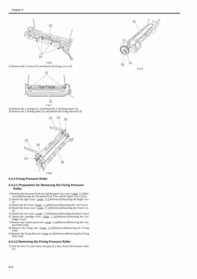
Chapter 6
6-4
F-6-62) Remove the 2 screws [1], and detach the fixing cover [2].
F-6-73) Remove the 2 springs [1], and detach the 2 releasing levers [2].4) Remove the 2 locking plate [3], and detach the fixing film unit [4].
F-6-8
6.4.3 Fixing Pressure Roller
6.4.3.1 Preparation for Removing the Fixing Pressure Roller
0018-4203
1) Remove the document feed tray and the paper tray cover. (page 7-2)Ref-erence[Removing the Document Feed Tray and the Paper Tray Cover]
2) Detach the right cover. (page 7-2)Reference[Detaching the Right Cov-er]
3) Detach the left cover. (page 7-2)Reference[Detaching the Left Cover]4) Detach the front cover. (page 7-1)Reference[Detaching the Front Cov-
er]5) Detach the rear cover. (page 7-1)Reference[Detaching the Rear Cover]6) Detach the cartridge cover. (page 7-3)Reference[Detaching the Car-
tridge Cover]7) Remove the control panel unit. (page 7-4)Rference[Removing the Con-
trol Panel Unit]8) Remove the fixing unit. (page 6-3)Reference[Removing the Fixing
Unit]9) Remove the fixing film unit. (page 6-3)Reference[Removing the Fixing
Film Unit]
6.4.3.2 Removing the Fixing Pressure Roller0018-4204
1) Free the claw [1], and remove the gear [2]; then, detach the Pressure roller[3].
F-6-9
[1]
[2]
[1]
[2]
[1]
[1]
[2]
[2]
[3]
[3]
[4]
[1][2]
[3]

Chapter 7 External and Controls

Contents
Contents
7.1 Power Supply .................................................................................................................................................................7-17.1.1 Protection Function ...................................................................................................................................................................... 7-1
7.1.1.1 Protective Mechanisms ...................................................................................................................................................................................7-17.1.2 Backup Battery............................................................................................................................................................................. 7-1
7.1.2.1 Battery-backed up Data...................................................................................................................................................................................7-17.2 Parts Replacement Procedure.........................................................................................................................................7-1
7.2.1 Front Cover .................................................................................................................................................................................. 7-17.2.1.1 Preparation for Detaching the Front Cover .....................................................................................................................................................7-17.2.1.2 Detaching the Front Cover ..............................................................................................................................................................................7-1
7.2.2 Rear Cover ................................................................................................................................................................................... 7-17.2.2.1 Preparation for Detaching the Rear Cover ......................................................................................................................................................7-17.2.2.2 Detaching the Rear Cover ...............................................................................................................................................................................7-1
7.2.3 Right Cover .................................................................................................................................................................................. 7-27.2.3.1 Preparation for Detaching the Right Cover.....................................................................................................................................................7-27.2.3.2 Detaching the Right Cover..............................................................................................................................................................................7-2
7.2.4 Left Cover .................................................................................................................................................................................... 7-27.2.4.1 Preparation for Detaching the Left Cover .......................................................................................................................................................7-27.2.4.2 Detaching the Left Cover ................................................................................................................................................................................7-2
7.2.5 External Cover ............................................................................................................................................................................. 7-27.2.5.1 Removing the Document Feed Tray and the Paper Tray Cover .....................................................................................................................7-2
7.2.6 Upper Cover................................................................................................................................................................................. 7-37.2.6.1 Preparation for Detaching the Upper Cover....................................................................................................................................................7-37.2.6.2 Detaching the Upper Cover.............................................................................................................................................................................7-3
7.2.7 Cartridge Cover............................................................................................................................................................................ 7-37.2.7.1 Preparation for Detaching the Cartridge Cover ..............................................................................................................................................7-37.2.7.2 Detaching the Cartridge Cover........................................................................................................................................................................7-3
7.2.8 Operation Panel Unit.................................................................................................................................................................... 7-47.2.8.1 Preparation for Removing the Control Panel Unit ..........................................................................................................................................7-47.2.8.2 Removing the Control Panel Unit ...................................................................................................................................................................7-4
7.2.9 SCNT Board................................................................................................................................................................................. 7-47.2.9.1 Preparation for Removing the SCNT Board ...................................................................................................................................................7-47.2.9.2 Removing the SCNT Board ............................................................................................................................................................................7-4
7.2.10 DCNT Board.............................................................................................................................................................................. 7-47.2.10.1 Preparation for Removing the DCNT Board ................................................................................................................................................7-47.2.10.2 Removing the DCNT Board..........................................................................................................................................................................7-4
7.2.11 High-voitage Power Supply PCB .............................................................................................................................................. 7-57.2.11.1 Preparation for Removing the High-Voltage Power Supply Board..............................................................................................................7-57.2.11.2 Removing the High-Voltage Power Supply Board.......................................................................................................................................7-5
7.2.12 Powwer Supply PCB.................................................................................................................................................................. 7-67.2.12.1 Preparation for Removing the Power Supply Board.....................................................................................................................................7-67.2.12.2 Removing the Power Supply Board..............................................................................................................................................................7-6
7.2.13 Top Sensor ................................................................................................................................................................................. 7-67.2.13.1 Preparation for Removing the Paper Leading Edge / the Paper Width Sensor PCB ....................................................................................7-67.2.13.2 Removing the Paper Leading Edge/ the Paper Width Sensor PCB ..............................................................................................................7-6
7.2.14 Paper Delivery Sensor................................................................................................................................................................ 7-67.2.14.1 Preparation for Removing the Paper Delivery Sensor PCB..........................................................................................................................7-67.2.14.2 Removing the Paper Delivery Sensor PCB...................................................................................................................................................7-6
7.2.15 Toner Sensor .............................................................................................................................................................................. 7-67.2.15.1 Preparation for Removing the Toner Sensor.................................................................................................................................................7-67.2.15.2 Removing the Toner Sensor..........................................................................................................................................................................7-7
7.2.16 Paper Width Sensor.................................................................................................................................................................... 7-77.2.16.1 Preparation for Removing the Paper Width Sensor PCB..............................................................................................................................7-77.2.16.2 Removing the Paper Width Sensor PCB.......................................................................................................................................................7-7

Contents
7.2.17 Speaker....................................................................................................................................................................................... 7-77.2.17.1 Preparation for Removing the Speaker ......................................................................................................................................................... 7-77.2.17.2 Removing the Speaker .................................................................................................................................................................................. 7-7
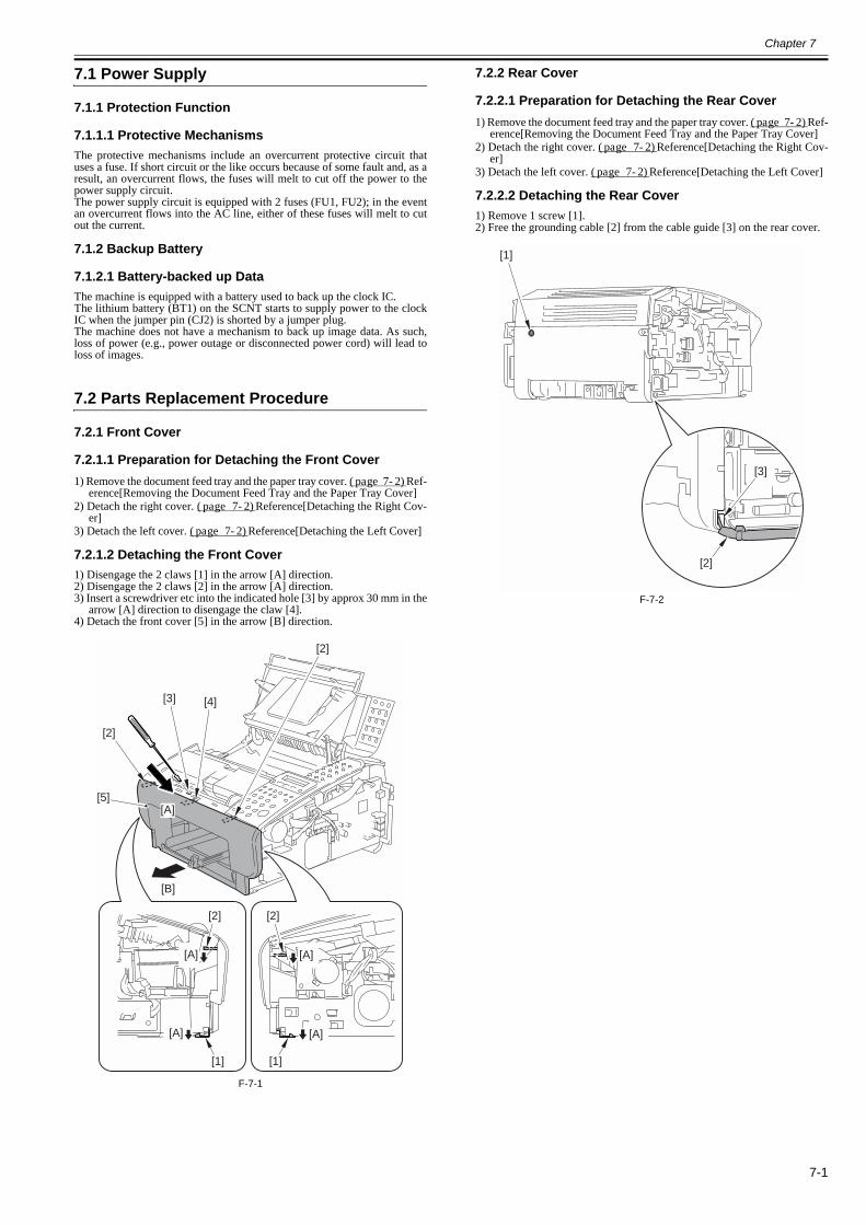
Chapter 7
7-1
7.1 Power Supply
7.1.1 Protection Function
7.1.1.1 Protective Mechanisms0018-4917
The protective mechanisms include an overcurrent protective circuit thatuses a fuse. If short circuit or the like occurs because of some fault and, as aresult, an overcurrent flows, the fuses will melt to cut off the power to thepower supply circuit.The power supply circuit is equipped with 2 fuses (FU1, FU2); in the eventan overcurrent flows into the AC line, either of these fuses will melt to cutout the current.
7.1.2 Backup Battery
7.1.2.1 Battery-backed up Data0018-4918
The machine is equipped with a battery used to back up the clock IC.The lithium battery (BT1) on the SCNT starts to supply power to the clockIC when the jumper pin (CJ2) is shorted by a jumper plug.The machine does not have a mechanism to back up image data. As such,loss of power (e.g., power outage or disconnected power cord) will lead toloss of images.
7.2 Parts Replacement Procedure
7.2.1 Front Cover
7.2.1.1 Preparation for Detaching the Front Cover0018-3823
1) Remove the document feed tray and the paper tray cover. (page 7-2)Ref-erence[Removing the Document Feed Tray and the Paper Tray Cover]
2) Detach the right cover. (page 7-2)Reference[Detaching the Right Cov-er]
3) Detach the left cover. (page 7-2)Reference[Detaching the Left Cover]
7.2.1.2 Detaching the Front Cover0018-3809
1) Disengage the 2 claws [1] in the arrow [A] direction.2) Disengage the 2 claws [2] in the arrow [A] direction.3) Insert a screwdriver etc into the indicated hole [3] by approx 30 mm in the
arrow [A] direction to disengage the claw [4].4) Detach the front cover [5] in the arrow [B] direction.
F-7-1
7.2.2 Rear Cover
7.2.2.1 Preparation for Detaching the Rear Cover0018-3915
1) Remove the document feed tray and the paper tray cover. (page 7-2)Ref-erence[Removing the Document Feed Tray and the Paper Tray Cover]
2) Detach the right cover. (page 7-2)Reference[Detaching the Right Cov-er]
3) Detach the left cover. (page 7-2)Reference[Detaching the Left Cover]
7.2.2.2 Detaching the Rear Cover0018-3912
1) Remove 1 screw [1].2) Free the grounding cable [2] from the cable guide [3] on the rear cover.
F-7-2
[2]
[1]
[2]
[A]
[A]
[A]
[B]
[5]
[2]
[3] [4]
[1]
[2]
[A]
[A]
[3]
[2]
[1]
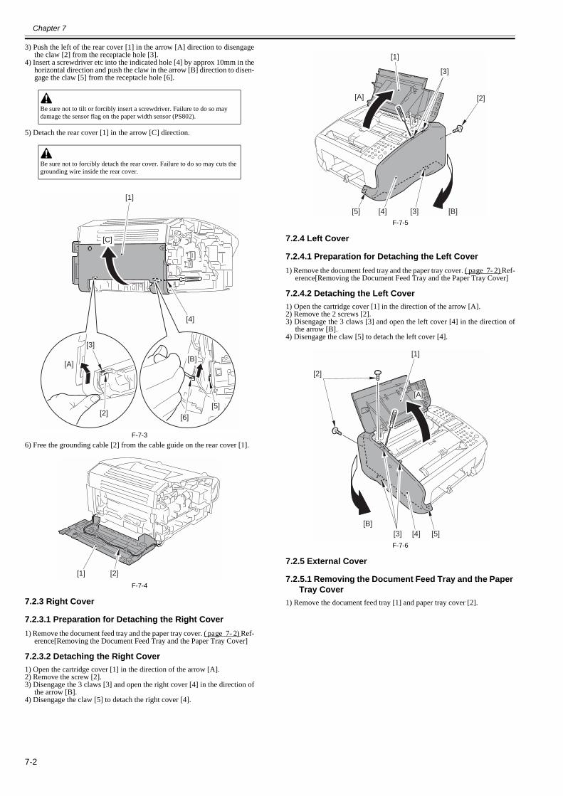
Chapter 7
7-2
3) Push the left of the rear cover [1] in the arrow [A] direction to disengagethe claw [2] from the receptacle hole [3].
4) Insert a screwdriver etc into the indicated hole [4] by approx 10mm in thehorizontal direction and push the claw in the arrow [B] direction to disen-gage the claw [5] from the receptacle hole [6].
5) Detach the rear cover [1] in the arrow [C] direction.
F-7-36) Free the grounding cable [2] from the cable guide on the rear cover [1].
F-7-4
7.2.3 Right Cover
7.2.3.1 Preparation for Detaching the Right Cover0018-3819
1) Remove the document feed tray and the paper tray cover. (page 7-2)Ref-erence[Removing the Document Feed Tray and the Paper Tray Cover]
7.2.3.2 Detaching the Right Cover0018-3820
1) Open the cartridge cover [1] in the direction of the arrow [A].2) Remove the screw [2].3) Disengage the 3 claws [3] and open the right cover [4] in the direction of
the arrow [B].4) Disengage the claw [5] to detach the right cover [4].
F-7-5
7.2.4 Left Cover
7.2.4.1 Preparation for Detaching the Left Cover0018-3821
1) Remove the document feed tray and the paper tray cover. (page 7-2)Ref-erence[Removing the Document Feed Tray and the Paper Tray Cover]
7.2.4.2 Detaching the Left Cover0018-3822
1) Open the cartridge cover [1] in the direction of the arrow [A].2) Remove the 2 screws [2].3) Disengage the 3 claws [3] and open the left cover [4] in the direction of
the arrow [B].4) Disengage the claw [5] to detach the left cover [4].
F-7-6
7.2.5 External Cover
7.2.5.1 Removing the Document Feed Tray and the Paper Tray Cover
0018-3818
1) Remove the document feed tray [1] and paper tray cover [2].
Be sure not to tilt or forcibly insert a screwdriver. Failure to do so may damage the sensor flag on the paper width sensor (PS802).
Be sure not to forcibly detach the rear cover. Failure to do so may cuts the grounding wire inside the rear cover.
[3]
[2]
[A][B]
[1]
[C]
[6]
[4]
[5]
[1] [2]
[1]
[A]
[B]
[2]
[3]
[3][4][5]
[1]
[A]
[B]
[2]
[3] [4] [5]
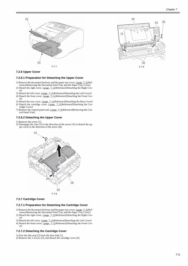
Chapter 7
7-3
F-7-7
7.2.6 Upper Cover
7.2.6.1 Preparation for Detaching the Upper Cover0018-3960
1) Remove the document feed tray and the paper tray cover. (page 7-2)Ref-erence[Removing the Document Feed Tray and the Paper Tray Cover]
2) Detach the right cover. (page 7-2)Reference[Detaching the Right Cov-er]
3) Detach the left cover. (page 7-2)Reference[Detaching the Left Cover]4) Detach the front cover. (page 7-1)Reference[Detaching the Front Cov-
er]5) Detach the rear cover. (page 7-1)Reference[Detaching the Rear Cover]6) Detach the cartridge cover. (page 7-3)Reference[Detaching the Car-
tridge Cover]7) Remove the control panel unit. (page 7-4)Rference[Removing the Con-
trol Panel Unit]
7.2.6.2 Detaching the Upper Cover0018-3962
1) Remove the screw [1].2) Disengage the claw [2] to the direction of the arrow [A] to detach the up-
per cover to the direction of the arrow [B].
F-7-8
7.2.7 Cartridge Cover
7.2.7.1 Preparation for Detaching the Cartridge Cover0018-3955
1) Remove the document feed tray and the paper tray cover. (page 7-2)Ref-erence[Removing the Document Feed Tray and the Paper Tray Cover]
2) Detach the right cover. (page 7-2)Reference[Detaching the Right Cov-er]
3) Detach the left cover. (page 7-2)Reference[Detaching the Left Cover]4) Detach the front cover. (page 7-1)Reference[Detaching the Front Cov-
er]
7.2.7.2 Detaching the Cartridge Cover0018-3917
1) Free the link stop [2] from the door link [1].2) Remove the 2 screws [3], and detach the cartridge cover [4].
F-7-9
[1]
[2]
[A]
[B]
[3]
[2]
[1]
[4][1]
[3]
[2]
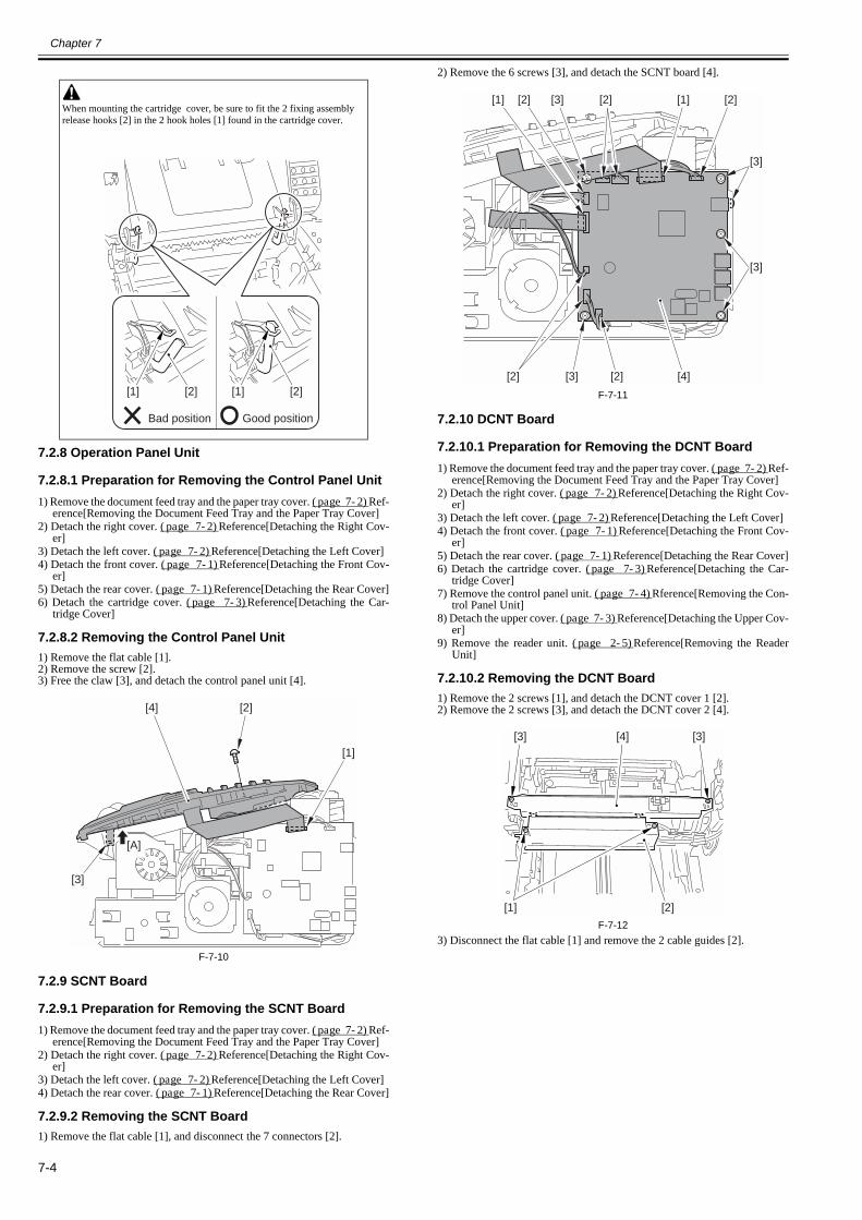
Chapter 7
7-4
7.2.8 Operation Panel Unit
7.2.8.1 Preparation for Removing the Control Panel Unit0018-3956
1) Remove the document feed tray and the paper tray cover. (page 7-2)Ref-erence[Removing the Document Feed Tray and the Paper Tray Cover]
2) Detach the right cover. (page 7-2)Reference[Detaching the Right Cov-er]
3) Detach the left cover. (page 7-2)Reference[Detaching the Left Cover]4) Detach the front cover. (page 7-1)Reference[Detaching the Front Cov-
er]5) Detach the rear cover. (page 7-1)Reference[Detaching the Rear Cover]6) Detach the cartridge cover. (page 7-3)Reference[Detaching the Car-
tridge Cover]
7.2.8.2 Removing the Control Panel Unit0018-3958
1) Remove the flat cable [1].2) Remove the screw [2].3) Free the claw [3], and detach the control panel unit [4].
F-7-10
7.2.9 SCNT Board
7.2.9.1 Preparation for Removing the SCNT Board0018-3964
1) Remove the document feed tray and the paper tray cover. (page 7-2)Ref-erence[Removing the Document Feed Tray and the Paper Tray Cover]
2) Detach the right cover. (page 7-2)Reference[Detaching the Right Cov-er]
3) Detach the left cover. (page 7-2)Reference[Detaching the Left Cover]4) Detach the rear cover. (page 7-1)Reference[Detaching the Rear Cover]
7.2.9.2 Removing the SCNT Board0018-3969
1) Remove the flat cable [1], and disconnect the 7 connectors [2].
2) Remove the 6 screws [3], and detach the SCNT board [4].
F-7-11
7.2.10 DCNT Board
7.2.10.1 Preparation for Removing the DCNT Board0018-3973
1) Remove the document feed tray and the paper tray cover. (page 7-2)Ref-erence[Removing the Document Feed Tray and the Paper Tray Cover]
2) Detach the right cover. (page 7-2)Reference[Detaching the Right Cov-er]
3) Detach the left cover. (page 7-2)Reference[Detaching the Left Cover]4) Detach the front cover. (page 7-1)Reference[Detaching the Front Cov-
er]5) Detach the rear cover. (page 7-1)Reference[Detaching the Rear Cover]6) Detach the cartridge cover. (page 7-3)Reference[Detaching the Car-
tridge Cover]7) Remove the control panel unit. (page 7-4)Rference[Removing the Con-
trol Panel Unit]8) Detach the upper cover. (page 7-3)Reference[Detaching the Upper Cov-
er]9) Remove the reader unit. (page 2-5)Reference[Removing the Reader
Unit]
7.2.10.2 Removing the DCNT Board0018-3980
1) Remove the 2 screws [1], and detach the DCNT cover 1 [2].2) Remove the 2 screws [3], and detach the DCNT cover 2 [4].
F-7-123) Disconnect the flat cable [1] and remove the 2 cable guides [2].
When mounting the cartridge cover, be sure to fit the 2 fixing assembly release hooks [2] in the 2 hook holes [1] found in the cartridge cover.
Good positionBad position
[1] [2][1] [2]
[3]
[2][4]
[A]
[1]
[4][2] [2][3]
[1] [2] [2] [2][3] [1]
[3]
[3]
[1] [2]
[3][3] [4]
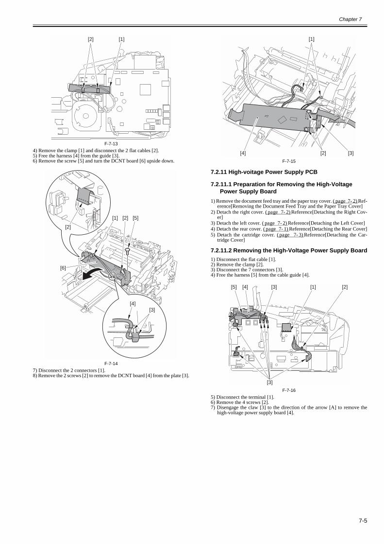
Chapter 7
7-5
F-7-134) Remove the clamp [1] and disconnect the 2 flat cables [2].5) Free the harness [4] from the guide [3].6) Remove the screw [5] and turn the DCNT board [6] upside down.
F-7-147) Disconnect the 2 connectors [1].8) Remove the 2 screws [2] to remove the DCNT board [4] from the plate [3].
F-7-15
7.2.11 High-voitage Power Supply PCB
7.2.11.1 Preparation for Removing the High-Voltage Power Supply Board
0018-4153
1) Remove the document feed tray and the paper tray cover. (page 7-2)Ref-erence[Removing the Document Feed Tray and the Paper Tray Cover]
2) Detach the right cover. (page 7-2)Reference[Detaching the Right Cov-er]
3) Detach the left cover. (page 7-2)Reference[Detaching the Left Cover]4) Detach the rear cover. (page 7-1)Reference[Detaching the Rear Cover]5) Detach the cartridge cover. (page 7-3)Reference[Detaching the Car-
tridge Cover]
7.2.11.2 Removing the High-Voltage Power Supply Board0018-4154
1) Disconnect the flat cable [1].2) Remove the clamp [2].3) Disconnect the 7 connectors [3].4) Free the harness [5] from the cable guide [4].
F-7-165) Disconnect the terminal [1].6) Remove the 4 screws [2].7) Disengage the claw [3] to the direction of the arrow [A] to remove the
high-voltage power supply board [4].
[2] [1]
[2]
[1] [2] [5]
[6]
[3][4]
[3][2][4]
[1]
[5] [4] [3] [1] [2]
[3]
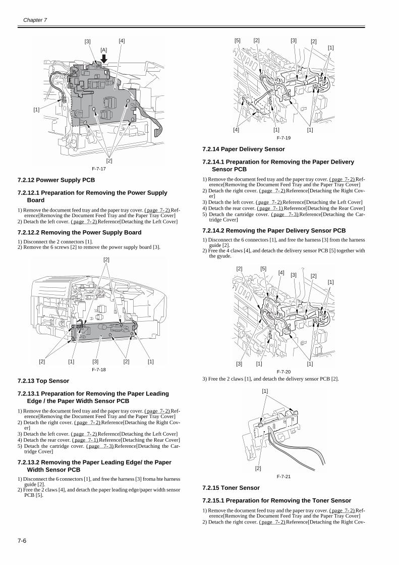
Chapter 7
7-6
F-7-17
7.2.12 Powwer Supply PCB
7.2.12.1 Preparation for Removing the Power Supply Board
0018-4149
1) Remove the document feed tray and the paper tray cover. (page 7-2)Ref-erence[Removing the Document Feed Tray and the Paper Tray Cover]
2) Detach the left cover. (page 7-2)Reference[Detaching the Left Cover]
7.2.12.2 Removing the Power Supply Board0018-4150
1) Disconnect the 2 connectors [1].2) Remove the 6 screws [2] to remove the power supply board [3].
F-7-18
7.2.13 Top Sensor
7.2.13.1 Preparation for Removing the Paper Leading Edge / the Paper Width Sensor PCB
0018-4155
1) Remove the document feed tray and the paper tray cover. (page 7-2)Ref-erence[Removing the Document Feed Tray and the Paper Tray Cover]
2) Detach the right cover. (page 7-2)Reference[Detaching the Right Cov-er]
3) Detach the left cover. (page 7-2)Reference[Detaching the Left Cover]4) Detach the rear cover. (page 7-1)Reference[Detaching the Rear Cover]5) Detach the cartridge cover. (page 7-3)Reference[Detaching the Car-
tridge Cover]
7.2.13.2 Removing the Paper Leading Edge/ the Paper Width Sensor PCB
0018-4156
1) Disconnect the 6 connectors [1], and free the harness [3] froma hte harnessguide [2].
2) Free the 2 claws [4], and detach the paper leading edge/paper width sensorPCB [5].
F-7-19
7.2.14 Paper Delivery Sensor
7.2.14.1 Preparation for Removing the Paper Delivery Sensor PCB
0018-4157
1) Remove the document feed tray and the paper tray cover. (page 7-2)Ref-erence[Removing the Document Feed Tray and the Paper Tray Cover]
2) Detach the right cover. (page 7-2)Reference[Detaching the Right Cov-er]
3) Detach the left cover. (page 7-2)Reference[Detaching the Left Cover]4) Detach the rear cover. (page 7-1)Reference[Detaching the Rear Cover]5) Detach the cartridge cover. (page 7-3)Reference[Detaching the Car-
tridge Cover]
7.2.14.2 Removing the Paper Delivery Sensor PCB0018-4160
1) Disconnect the 6 connectors [1], and free the harness [3] from the harnessguide [2].
2) Free the 4 claws [4], and detach the delivery sensor PCB [5] together withthe gyude.
F-7-203) Free the 2 claws [1], and detach the delivery sensor PCB [2].
F-7-21
7.2.15 Toner Sensor
7.2.15.1 Preparation for Removing the Toner Sensor0018-4161
1) Remove the document feed tray and the paper tray cover. (page 7-2)Ref-erence[Removing the Document Feed Tray and the Paper Tray Cover]
2) Detach the right cover. (page 7-2)Reference[Detaching the Right Cov-
[1]
[2]
[3] [4]
[A]
[2]
[2] [3] [1][1] [2]
[4]
[5]
[1]
[2][3]
[1]
[1][2]
[4][5]
[2][3]
[1]
[1]
[1]
[2]
[3]
[1]
[2]
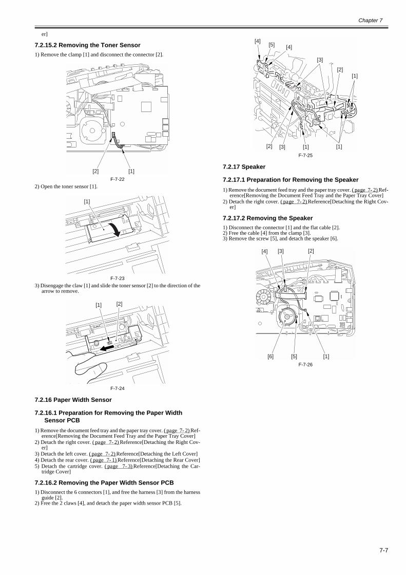
Chapter 7
7-7
er]
7.2.15.2 Removing the Toner Sensor0018-4162
1) Remove the clamp [1] and disconnect the connector [2].
F-7-222) Open the toner sensor [1].
F-7-233) Disengage the claw [1] and slide the toner sensor [2] to the direction of the
arrow to remove.
F-7-24
7.2.16 Paper Width Sensor
7.2.16.1 Preparation for Removing the Paper Width Sensor PCB
0018-4163
1) Remove the document feed tray and the paper tray cover. (page 7-2)Ref-erence[Removing the Document Feed Tray and the Paper Tray Cover]
2) Detach the right cover. (page 7-2)Reference[Detaching the Right Cov-er]
3) Detach the left cover. (page 7-2)Reference[Detaching the Left Cover]4) Detach the rear cover. (page 7-1)Reference[Detaching the Rear Cover]5) Detach the cartridge cover. (page 7-3)Reference[Detaching the Car-
tridge Cover]
7.2.16.2 Removing the Paper Width Sensor PCB0018-4164
1) Disconnect the 6 connectors [1], and free the harness [3] from the harnessguide [2].
2) Free the 2 claws [4], and detach the paper width sensor PCB [5].
F-7-25
7.2.17 Speaker
7.2.17.1 Preparation for Removing the Speaker0018-4165
1) Remove the document feed tray and the paper tray cover. (page 7-2)Ref-erence[Removing the Document Feed Tray and the Paper Tray Cover]
2) Detach the right cover. (page 7-2)Reference[Detaching the Right Cov-er]
7.2.17.2 Removing the Speaker0018-4166
1) Disconnect the connector [1] and the flat cable [2].2) Free the cable [4] from the clamp [3].3) Remove the screw [5], and detach the speaker [6].
F-7-26
[2] [1]
[1]
[1] [2]
[3]
[1]
[1]
[4][4]
[2]
[1][3][2]
[5]
[2]
[1]
[3][4]
[5][6]


Chapter 8 Maintenance and Inspection

Contents
Contents
8.1 Periodically Replaced Parts ...........................................................................................................................................8-18.1.1 Periodic Replacement Parts ......................................................................................................................................................... 8-1
8.2 Consumables ..................................................................................................................................................................8-18.2.1 Consumable.................................................................................................................................................................................. 8-1
8.3 Periodical Service ..........................................................................................................................................................8-18.3.1 Scheduled service Parts................................................................................................................................................................ 8-1
8.4 Cleaning .........................................................................................................................................................................8-18.4.1 Items Requiring Cleaning ............................................................................................................................................................ 8-18.4.2 Cleaning Method (external covers).............................................................................................................................................. 8-28.4.3 Cleaning Method (scanning unit)................................................................................................................................................. 8-28.4.4 Cleaning (printer unit).................................................................................................................................................................. 8-3

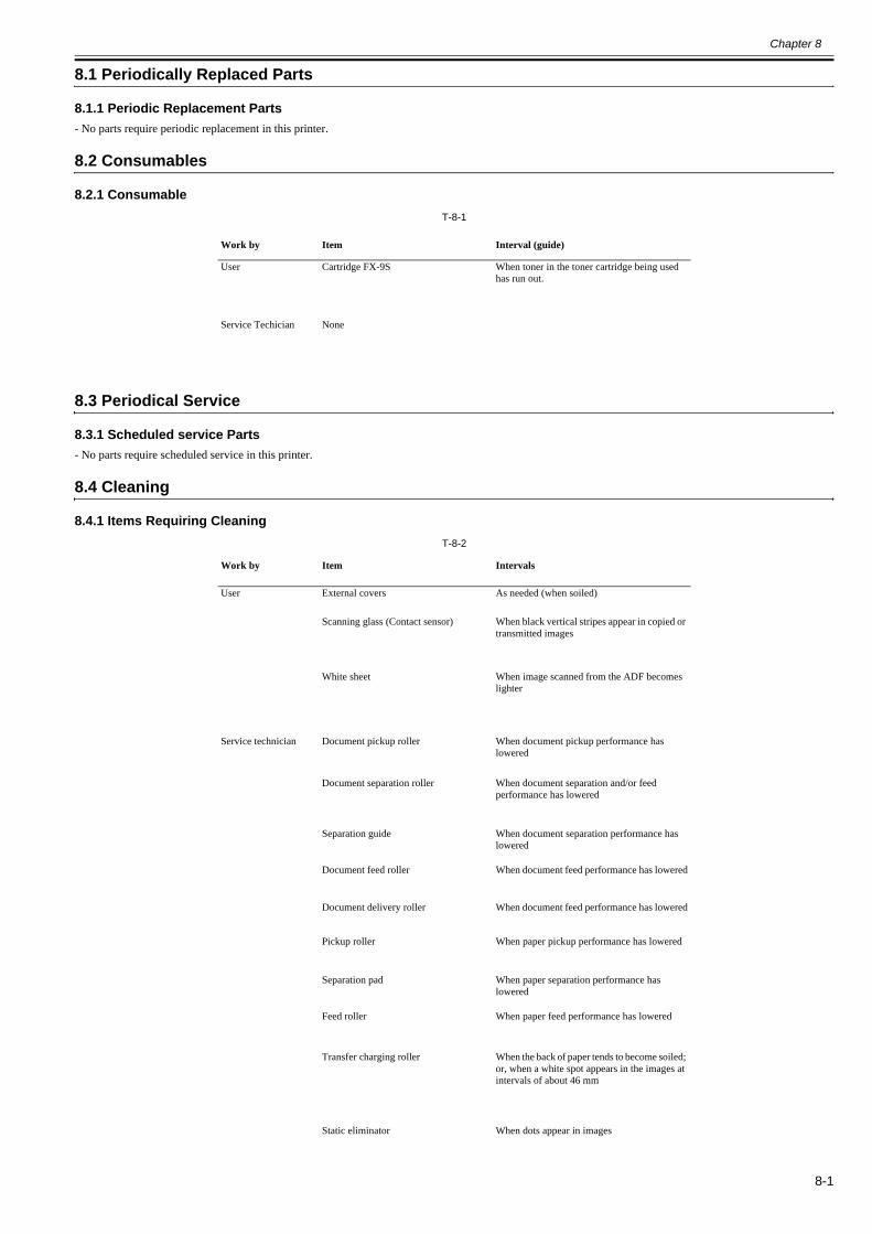
Chapter 8
8-1
8.1 Periodically Replaced Parts
8.1.1 Periodic Replacement Parts0018-4922
- No parts require periodic replacement in this printer.
8.2 Consumables
8.2.1 Consumable0018-4924
T-8-1
8.3 Periodical Service
8.3.1 Scheduled service Parts0018-4927
- No parts require scheduled service in this printer.
8.4 Cleaning
8.4.1 Items Requiring Cleaning0018-4928
T-8-2
Work by Item Interval (guide)
User Cartridge FX-9S When toner in the toner cartridge being used has run out.
Service Techician None
Work by Item Intervals
User External covers As needed (when soiled)
Scanning glass (Contact sensor) When black vertical stripes appear in copied or transmitted images
White sheet When image scanned from the ADF becomes lighter
Service technician Document pickup roller When document pickup performance has lowered
Document separation roller When document separation and/or feed performance has lowered
Separation guide When document separation performance has lowered
Document feed roller When document feed performance has lowered
Document delivery roller When document feed performance has lowered
Pickup roller When paper pickup performance has lowered
Separation pad When paper separation performance has lowered
Feed roller When paper feed performance has lowered
Transfer charging roller When the back of paper tends to become soiled; or, when a white spot appears in the images at intervals of about 46 mm
Static eliminator When dots appear in images
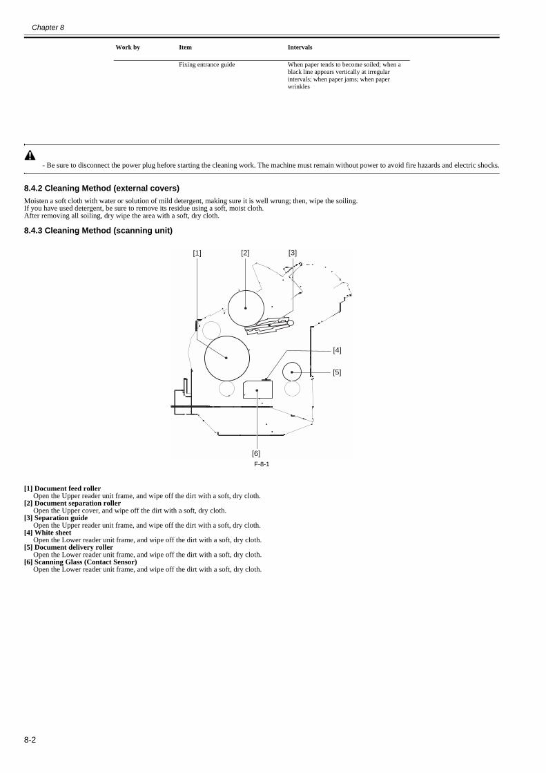
Chapter 8
8-2
- Be sure to disconnect the power plug hefore starting the cleaning work. The machine must remain without power to avoid fire hazards and electric shocks.
8.4.2 Cleaning Method (external covers)0018-4930
Moisten a soft cloth with water or solution of mild detergent, making sure it is well wrung; then, wipe the soiling.If you have used detergent, be sure to remove its residue using a soft, moist cloth.After removing all soiling, dry wipe the area with a soft, dry cloth.
8.4.3 Cleaning Method (scanning unit)0018-4932
F-8-1
[1] Document feed rollerOpen the Upper reader unit frame, and wipe off the dirt with a soft, dry cloth.
[2] Document separation rollerOpen the Upper cover, and wipe off the dirt with a soft, dry cloth.
[3] Separation guideOpen the Upper reader unit frame, and wipe off the dirt with a soft, dry cloth.
[4] White sheetOpen the Lower reader unit frame, and wipe off the dirt with a soft, dry cloth.
[5] Document delivery rollerOpen the Lower reader unit frame, and wipe off the dirt with a soft, dry cloth.
[6] Scanning Glass (Contact Sensor)Open the Lower reader unit frame, and wipe off the dirt with a soft, dry cloth.
Fixing entrance guide When paper tends to become soiled; when a black line appears vertically at irregular intervals; when paper jams; when paper wrinkles
Work by Item Intervals
[1] [2] [3]
[4]
[5]
[6]
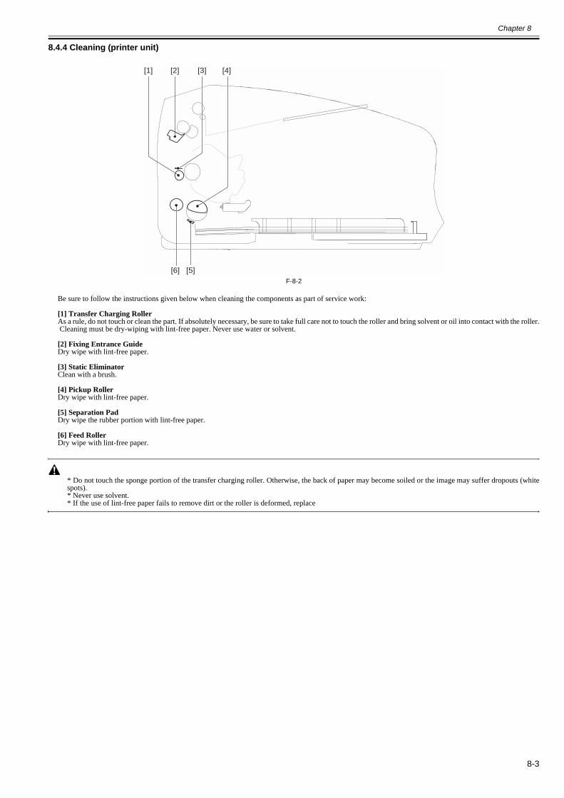
Chapter 8
8-3
8.4.4 Cleaning (printer unit)0018-4933
F-8-2
Be sure to follow the instructions given below when cleaning the components as part of service work:
[1] Transfer Charging RollerAs a rule, do not touch or clean the part. If absolutely necessary, be sure to take full care not to touch the roller and bring solvent or oil into contact with the roller. Cleaning must be dry-wiping with lint-free paper. Never use water or solvent.
[2] Fixing Entrance GuideDry wipe with lint-free paper.
[3] Static EliminatorClean with a brush.
[4] Pickup RollerDry wipe with lint-free paper.
[5] Separation PadDry wipe the rubber portion with lint-free paper.
[6] Feed RollerDry wipe with lint-free paper.
* Do not touch the sponge portion of the transfer charging roller. Otherwise, the back of paper may become soiled or the image may suffer dropouts (whitespots).* Never use solvent.* If the use of lint-free paper fails to remove dirt or the roller is deformed, replace
[1] [2] [3] [4]
[5][6]


Chapter 9 Measurement and Adjustments


Contents
Contents
9.1 Image Adjustments ........................................................................................................................................................9-19.1.1 Adjusting the Paper Margin ......................................................................................................................................................... 9-19.1.2 Read Adjustment.......................................................................................................................................................................... 9-19.1.3 Print Adjustment .......................................................................................................................................................................... 9-1

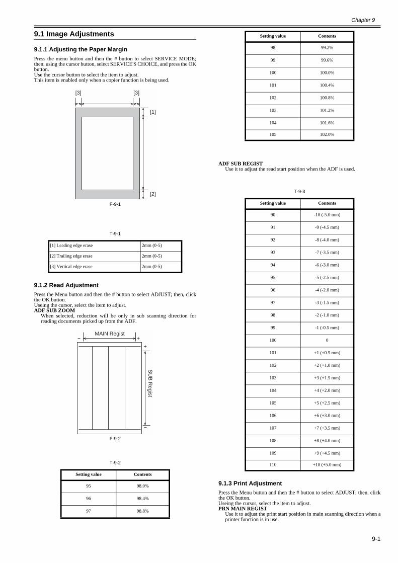
Chapter 9
9-1
9.1 Image Adjustments
9.1.1 Adjusting the Paper Margin0018-4998
Press the menu button and then the # button to select SERVICE MODE;then, using the cursor button, select SERVICE'S CHOICE, and press the OKbutton.Use the cursor button to select the item to adjust.This item is enabled only when a copier function is being used.
F-9-1
T-9-1
9.1.2 Read Adjustment0018-5000
Press the Menu button and then the # button to select ADJUST; then, clickthe OK button.Useing the cursor, select the item to adjust.ADF SUB ZOOM
When selected, reduction will be only in sub scanning direction forreading documents picked up from the ADF.
F-9-2
T-9-2
ADF SUB REGISTUse it to adjust the read start position when the ADF is used.
T-9-3
9.1.3 Print Adjustment0018-5002
Press the Menu button and then the # button to select ADJUST; then, clickthe OK button.Useing the cursor, select the item to adjust.PRN MAIN REGIST
Use it to adjust the print start position in main scanning direction when aprinter function is in use.
[1] Leading edge erase 2mm (0-5)
[2] Trailing edge erase 2mm (0-5)
[3] Vertical edge erase 2mm (0-5)
Setting value Contents
95 98.0%
96 98.4%
97 98.8%
[1]
[2]
[3] [3]
+
+
MAIN Regist
SU
B R
egist
98 99.2%
99 99.6%
100 100.0%
101 100.4%
102 100.8%
103 101.2%
104 101.6%
105 102.0%
Setting value Contents
90 -10 (-5.0 mm)
91 -9 (-4.5 mm)
92 -8 (-4.0 mm)
93 -7 (-3.5 mm)
94 -6 (-3.0 mm)
95 -5 (-2.5 mm)
96 -4 (-2.0 mm)
97 -3 (-1.5 mm)
98 -2 (-1.0 mm)
99 -1 (-0.5 mm)
100 0
101 +1 (+0.5 mm)
102 +2 (+1.0 mm)
103 +3 (+1.5 mm)
104 +4 (+2.0 mm)
105 +5 (+2.5 mm)
106 +6 (+3.0 mm)
107 +7 (+3.5 mm)
108 +8 (+4.0 mm)
109 +9 (+4.5 mm)
110 +10 (+5.0 mm)
Setting value Contents
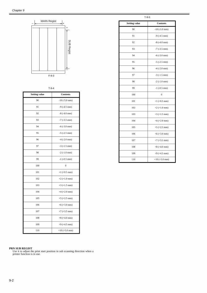
Chapter 9
9-2
F-9-3
T-9-4
PRN SUB REGISTUse it to adjust the print start position in sub scanning direction when aprinter function is in use.
T-9-5
Setting value Contents
90 -10 (-5.0 mm)
91 -9 (-4.5 mm)
92 -8 (-4.0 mm)
93 -7 (-3.5 mm)
94 -6 (-3.0 mm)
95 -5 (-2.5 mm)
96 -4 (-2.0 mm)
97 -3 (-1.5 mm)
98 -2 (-1.0 mm)
99 -1 (-0.5 mm)
100 0
101 +1 (+0.5 mm)
102 +2 (+1.0 mm)
103 +3 (+1.5 mm)
104 +4 (+2.0 mm)
105 +5 (+2.5 mm)
106 +6 (+3.0 mm)
107 +7 (+3.5 mm)
108 +8 (+4.0 mm)
109 +9 (+4.5 mm)
110 +10 (+5.0 mm)
+
+
MAIN Regist
SU
B R
egist
Setting value Contents
90 -10 (-5.0 mm)
91 -9 (-4.5 mm)
92 -8 (-4.0 mm)
93 -7 (-3.5 mm)
94 -6 (-3.0 mm)
95 -5 (-2.5 mm)
96 -4 (-2.0 mm)
97 -3 (-1.5 mm)
98 -2 (-1.0 mm)
99 -1 (-0.5 mm)
100 0
101 +1 (+0.5 mm)
102 +2 (+1.0 mm)
103 +3 (+1.5 mm)
104 +4 (+2.0 mm)
105 +5 (+2.5 mm)
106 +6 (+3.0 mm)
107 +7 (+3.5 mm)
108 +8 (+4.0 mm)
109 +9 (+4.5 mm)
110 +10 (+5.0 mm)

Chapter 10 Correcting Faulty Images


Contents
Contents
10.1 Troubleshooting .........................................................................................................................................................10-110.1.1 Phenomenon Table................................................................................................................................................................... 10-1
10.1.1.1 Symptoms....................................................................................................................................................................................................10-110.2 Outline of Electrical Components..............................................................................................................................10-1
10.2.1 Sensor....................................................................................................................................................................................... 10-110.2.1.1 Arrangement of Sensors and Switches........................................................................................................................................................10-1
10.2.2 PCBs ........................................................................................................................................................................................ 10-210.2.2.1 Arrangement of PCBs .................................................................................................................................................................................10-2

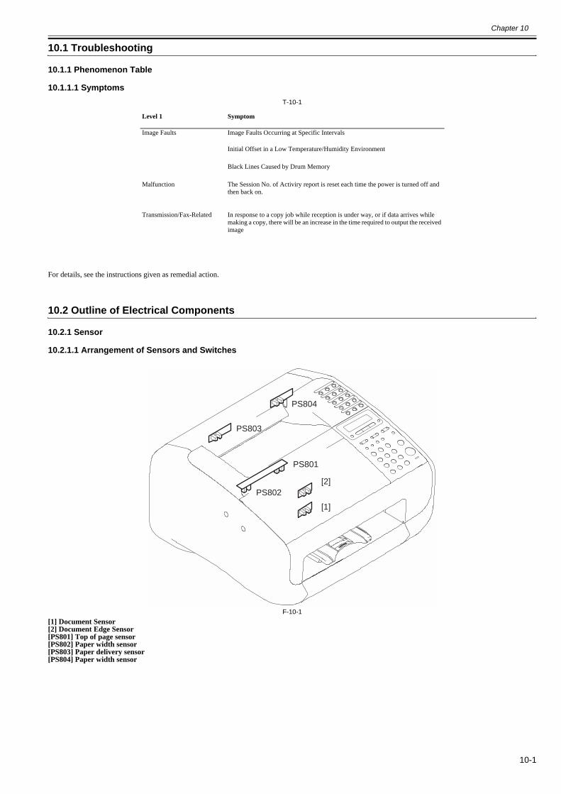
Chapter 10
10-1
10.1 Troubleshooting
10.1.1 Phenomenon Table
10.1.1.1 Symptoms0018-5004
T-10-1
For details, see the instructions given as remedial action.
10.2 Outline of Electrical Components
10.2.1 Sensor
10.2.1.1 Arrangement of Sensors and Switches0018-4209
F-10-1[1] Document Sensor[2] Document Edge Sensor[PS801] Top of page sensor[PS802] Paper width sensor[PS803] Paper delivery sensor[PS804] Paper width sensor
Level 1 Symptom
Image Faults Image Faults Occurring at Specific Intervals
Initial Offset in a Low Temperature/Humidity Environment
Black Lines Caused by Drum Memory
Malfunction The Session No. of Activiry report is reset each time the power is turned off and then back on.
Transmission/Fax-Related In response to a copy job while reception is under way, or if data arrives while making a copy, there will be an increase in the time required to output the received image
PS803
PS804
PS802
PS801
[1]
[2]
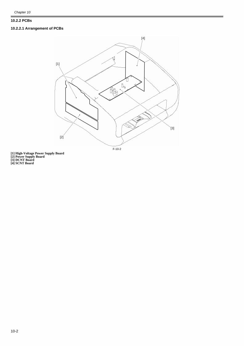
Chapter 10
10-2
10.2.2 PCBs
10.2.2.1 Arrangement of PCBs0018-4210
F-10-2[1] High-Voltage Power Supply Board[2] Power Supply Board[3] DCNT Board[4] SCNT Board
[1]
[2]
[3]
[4]

Chapter 11 Error Code


Contents
Contents
11.1 Error Code..................................................................................................................................................................11-111.1.1 Error Code................................................................................................................................................................................ 11-1

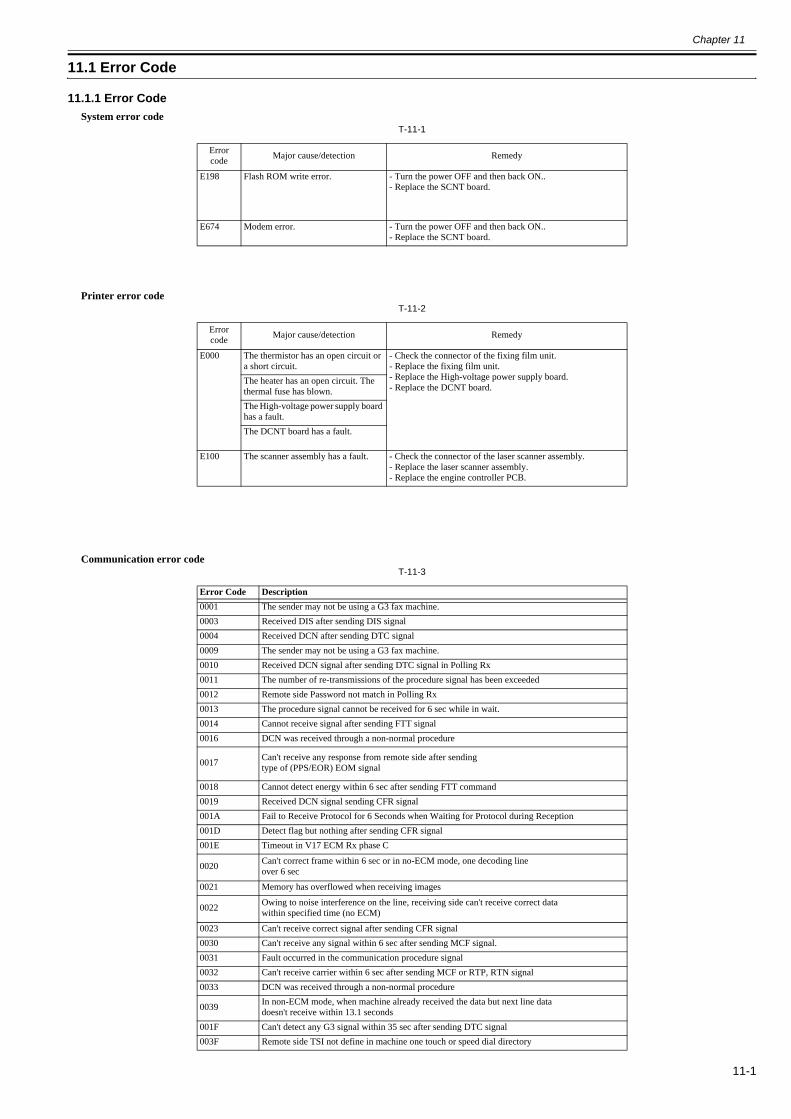
Chapter 11
11-1
11.1 Error Code
11.1.1 Error Code0018-5043
System error codeT-11-1
Printer error codeT-11-2
Communication error codeT-11-3
Error code Major cause/detection Remedy
E198 Flash ROM write error. - Turn the power OFF and then back ON..- Replace the SCNT board.
E674 Modem error. - Turn the power OFF and then back ON..- Replace the SCNT board.
Error code Major cause/detection Remedy
E000 The thermistor has an open circuit or a short circuit.
- Check the connector of the fixing film unit.- Replace the fixing film unit.- Replace the High-voltage power supply board.- Replace the DCNT board.
The heater has an open circuit. The thermal fuse has blown.The High-voltage power supply board has a fault.The DCNT board has a fault.
E100 The scanner assembly has a fault. - Check the connector of the laser scanner assembly.- Replace the laser scanner assembly.- Replace the engine controller PCB.
Error Code Description0001 The sender may not be using a G3 fax machine.0003 Received DIS after sending DIS signal0004 Received DCN after sending DTC signal0009 The sender may not be using a G3 fax machine.0010 Received DCN signal after sending DTC signal in Polling Rx0011 The number of re-transmissions of the procedure signal has been exceeded0012 Remote side Password not match in Polling Rx0013 The procedure signal cannot be received for 6 sec while in wait.0014 Cannot receive signal after sending FTT signal0016 DCN was received through a non-normal procedure
0017 Can't receive any response from remote side after sending type of (PPS/EOR) EOM signal
0018 Cannot detect energy within 6 sec after sending FTT command0019 Received DCN signal sending CFR signal001A Fail to Receive Protocol for 6 Seconds when Waiting for Protocol during Reception001D Detect flag but nothing after sending CFR signal001E Timeout in V17 ECM Rx phase C
0020 Can't correct frame within 6 sec or in no-ECM mode, one decoding lineover 6 sec
0021 Memory has overflowed when receiving images
0022 Owing to noise interference on the line, receiving side can't receive correct datawithin specified time (no ECM)
0023 Can't receive correct signal after sending CFR signal0030 Can't receive any signal within 6 sec after sending MCF signal.0031 Fault occurred in the communication procedure signal0032 Can't receive carrier within 6 sec after sending MCF or RTP, RTN signal0033 DCN was received through a non-normal procedure
0039 In non-ECM mode, when machine already received the data but next line datadoesn't receive within 13.1 seconds
001F Can't detect any G3 signal within 35 sec after sending DTC signal003F Remote side TSI not define in machine one touch or speed dial directory
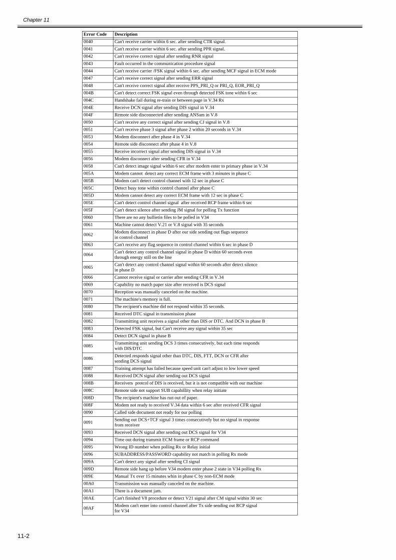
Chapter 11
11-2
0040 Can't receive carrier within 6 sec. after sending CTR signal.0041 Can't receive carrier within 6 sec. after sending PPR signal.0042 Can't receive correct signal after sending RNR signal0043 Fault occurred in the communication procedure signal0044 Can't receive carrier /FSK signal within 6 sec. after sending MCF signal in ECM mode0047 Can't receive correct signal after sending ERR signal0048 Can't receive correct signal after receive PPS_PRI_Q or PRI_Q, EOR_PRI_Q004B Can't detect correct FSK signal even through detected FSK tone within 6 sec004C Handshake fail during re-train or between page in V.34 Rx004E Receive DCN signal after sending DIS signal in V.34004F Remote side disconnected after sending ANSam in V.80050 Can't receive any correct signal after sending CJ signal in V.80051 Can't receive phase 3 signal after phase 2 within 20 seconds in V.340053 Modem disconnect after phase 4 in V.340054 Remote side disconnect after phase 4 in V.80055 Receive incorrect signal after sending DIS signal in V.340056 Modem disconnect after sending CFR in V.340058 Can't detect image signal within 6 sec after modem enter to primary phase in V.34005A Modem cannot detect any correct ECM frame with 3 minutes in phase C005B Modem can't detect control channel with 12 sec in phase C005C Detect busy tone within control channel after phase C005D Modem cannot detect any correct ECM frame with 12 sec in phase C005E Can't detect control channel signal after received RCP frame within 6 sec005F Can't detect silence after sending JM signal for polling Tx function0060 There are no any bullietin files to be polled in V340061 Machine cannot detect V.21 or V.8 signal with 35 seconds
0062 Modem disconnect in phase D after our side sending out flags sequencein control channel
0063 Can't receive any flag sequence in control channel within 6 sec in phase D
0064 Can't detect any control channel signal in phase D within 60 seconds eventhrough energy still on the line
0065 Can't detect any control channel signal within 60 seconds after detect silencein phase D
0066 Cannot receive signal or carrier after sending CFR in V.340069 Capability no match paper size after received is DCS signal0070 Reception was manually canceled on the machine.0071 The machine's memory is full.0080 The recipient's machine did not respond within 35 seconds.0081 Received DTC signal in transmission phase0082 Transmitting unit receives a signal other than DIS or DTC. And DCN in phase B0083 Detected FSK signal, but Can't receive any signal within 35 sec0084 Detect DCN signal in phase B
0085 Transmitting unit sending DCS 3 times consecutively, but each time responds with DIS/DTC
0086 Detected responds signal other than DTC, DIS, FTT, DCN or CFR aftersending DCS signal
0087 Training attempt has failed because speed unit can't adjust to low lower speed0088 Received DCN signal after sending out DCS signal008B Receivers protcol of DIS is received, but it is not compatible with our machine008C Remote side not support SUB capabillity when relay initiate008D The recipient's machine has run out of paper.008F Modem not ready to received V.34 data within 6 sec after received CFR signal0090 Called side document not ready for our polling
0091 Sending out DCS+TCF signal 3 times consecutively but no signal in responsefrom receiver
0093 Received DCN signal after sending out DCS signal for V340094 Time out during transmit ECM frame or RCP command0095 Wrong ID number when polling Rx or Relay initial0096 SUBADDRESS/PASSWORD capability not match in polling Rx mode009A Can't detect any signal after sending CI signal009D Remote side hang up before V34 modem enter phase 2 state in V34 polling Rx009E Manual Tx over 15 minutes whin in phase C by non-ECM mode00A0 Transmission was manually canceled on the machine.00A1 There is a document jam.00AE Can't finished V8 procedure or detect V21 signal after CM signal within 30 sec
00AF Modem can't enter into control channel after Tx side sending out RCP signalfor V34
Error Code Description
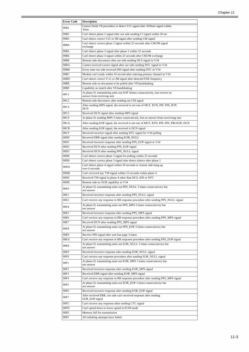
Chapter 11
11-3
00B1 Cannot finish V8 procedure or detect V21 signal after ANSam signal within35sec
00B2 Can't detect phase 2 signal after our side sending CJ signal within 30 sec00B3 Can't detect correct V21 or JM signal after sending CM signal
00B4 Can't detect correct phase 2 signal within 25 seconds after CM/JM signalexchange
00B5 Can't detect phase 3 signal after phase 2 within 25 seconds00B6 Can't detect phase 4 signal within 25 seconds after CM/JM exchange00B8 Remote side disconnect after our side sending DCS signal in V3400BA Cannot received correct signal after our side sending DTC signal in V3400BB Every time our side received DIS signal after sending DTC in V3400BC Modem can't ready within 10 second after entering primary channel in V3400BD Can't detect correct V.21 or JM signal after detected FSK frequency00BE Remote side no document to be polled after V8 handshaking00BF Capability no match after V8 handshaking
00C1 At phase D, transmitting units out EOP 3times consecutively, but receive no answer from receiving unit
00C2 Remote side disconnect after sending out CM signal
00C4 After sending MPS signal, the received is not one of MCF, RTN, PIP, PIN, RTP, DCN
00C5 Received DCN signal after sending MPS signal00C9 At phase D, sending MPS 3 times consecutively, but no answer from receiveing unit
00CA After sending EOP signal, the received is not one of MCF, RTN, PIP, PIN, PRI-EOP, DCN
00CB After sending EOP signal, the received is DCN signal00CF Received incorrect signal after sending DTC signal for V34 polling00D0 Received ERR signal after sending EOR_NULL00D1 Received incorrect response after sending PPS_EOP signal in V3400D2 Received DCN after sending PPS_EOP signal00D3 Received DCN after sending PPS_NULL signal00D8 Can't detect correct phase 3 signal for polling within 25 seconds00D9 Can't detect correct phase 3 signal after detect silence after phase 2
00DA Can't detect phase 4 signal within 30 seconds or remote side hang upover 6 seconds
00DB Can't received any T30 signal within 15 seconds within phase 400DC Received T30 signal in phase 4 other than DCS, DIS or DTC00DE Remote side no SUB capability in V34
00E0 At phase D, transmitting units out PPS_NULL 3 times consecutivery but not answer
00E1 Received incorrect response after sending PPS_NULL signal
00E2 Can't receive any response in RR response procedure after sending PPS_NULL signal
00E4 At phase D, transmitting units out PPS_MPS 3 times consecutivery but not answer
00E5 Received incorrect response after sending PPS_MPS signal00E6 Can't receive any response in RR response procedure after sending PPS_MPS signal00E7 Received DCN after sending PPS_MPS signal
00E8 At phase D, transmitting units out PPS_EOP 3 times consecutivery but not answer
00E9 Receive PIN signal after sent last page 3 times00EA Can't receive any response in RR response procedure after sending PPS_EOP signal
00EE At phase D, transmitting units out EOR_NULL 3 times consecutivery but not answer
00EF Received incorrect response after sending EOR_NULL signal00F0 Can't receive any response procedure after sending EOR_NULL signal
00F1 At phase D, transmitting units out EOR_MPS 3 times consecutivery but not answer
00F2 Received incorrect response after sending EOR_MPS signal00F3 Received ERR signal after sending EOR_MPS signal00F4 Can't receive any response in RR response procedure after sending PPS_MPS signal
00F5 At phase D, transmitting units out EOR_EOP 3 times consecutivery but not answer
00F6 Received incorrect response after sending EOR_EOP signal
00F7 After received ERR, our side can't received response after sendingEOR_EOP signal
00FC Can't receive any response ather sending CTC signal00FD Can't speed down to lower speed in ECM mode00FE Memory full for transmission00FF All redialing attempts have failed.
Error Code Description


Chapter 12 Service Mode

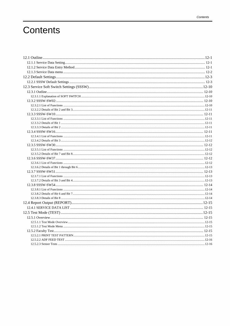
Contents
Contents
12.1 Outline........................................................................................................................................................................12-112.1.1 Service Data Setting................................................................................................................................................................. 12-112.1.2 Service Data Entry Method...................................................................................................................................................... 12-112.1.3 Service Data menu ................................................................................................................................................................... 12-2
12.2 Default Settings..........................................................................................................................................................12-312.2.1 SSSW Default Settings ............................................................................................................................................................ 12-3
12.3 Service Soft Switch Settings (SSSW)......................................................................................................................12-1012.3.1 Outline.................................................................................................................................................................................... 12-10
12.3.1.1 Explanation of SOFT SWITCH ................................................................................................................................................................12-1012.3.2 SSSW-SW02:......................................................................................................................................................................... 12-10
12.3.2.1 List of Functions .......................................................................................................................................................................................12-1012.3.2.2 Details of Bit 2 and Bit 3...........................................................................................................................................................................12-11
12.3.3 SSSW-SW10.......................................................................................................................................................................... 12-1112.3.3.1 List of Functions .......................................................................................................................................................................................12-1112.3.3.2 Details of Bit 1 ..........................................................................................................................................................................................12-1112.3.3.3 Details of Bit 2 ..........................................................................................................................................................................................12-11
12.3.4 SSSW-SW16.......................................................................................................................................................................... 12-1112.3.4.1 List of Functions .......................................................................................................................................................................................12-1112.3.4.2 Details of Bit 3 ..........................................................................................................................................................................................12-12
12.3.5 SSSW-SW30.......................................................................................................................................................................... 12-1212.3.5.1 List of Functions .......................................................................................................................................................................................12-1212.3.5.2 Details of Bit 7 and Bit 8...........................................................................................................................................................................12-12
12.3.6 SSSW-SW37.......................................................................................................................................................................... 12-1212.3.6.1 List of Functions .......................................................................................................................................................................................12-1212.3.6.2 Details of Bit 1 through Bit 6 ....................................................................................................................................................................12-13
12.3.7 SSSW-SW51.......................................................................................................................................................................... 12-1312.3.7.1 List of Functions .......................................................................................................................................................................................12-1312.3.7.2 Details of Bit 3 and Bit 4...........................................................................................................................................................................12-13
12.3.8 SSSW-SW54.......................................................................................................................................................................... 12-1412.3.8.1 List of Functions .......................................................................................................................................................................................12-1412.3.8.2 Details of Bit 6 and Bit 7...........................................................................................................................................................................12-1412.3.8.3 Details of Bit 8 ..........................................................................................................................................................................................12-14
12.4 Report Output (REPORT)........................................................................................................................................12-1512.4.1 SERVICE DATA LIST ......................................................................................................................................................... 12-15
12.5 Test Mode (TEST) ...................................................................................................................................................12-1512.5.1 Overview................................................................................................................................................................................ 12-15
12.5.1.1 Test Mode Overview.................................................................................................................................................................................12-1512.5.1.2 Test Mode Menu .......................................................................................................................................................................................12-15
12.5.2 Faculty Test............................................................................................................................................................................ 12-1512.5.2.1 PRINT TEST PATTERN..........................................................................................................................................................................12-1512.5.2.2 ADF FEED TEST .....................................................................................................................................................................................12-1612.5.2.3 Sensor Tests ..............................................................................................................................................................................................12-16

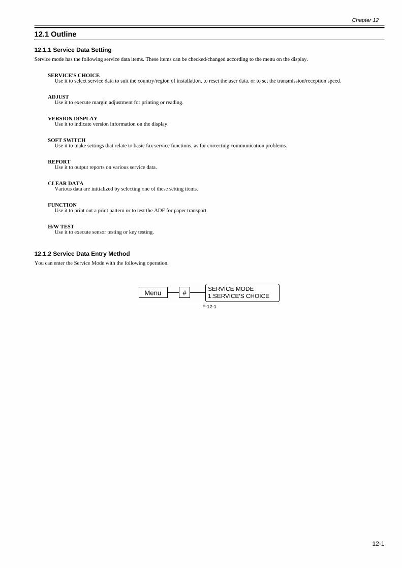
Chapter 12
12-1
12.1 Outline
12.1.1 Service Data Setting0018-5009
Service mode has the following service data items. These items can be checked/changed according to the menu on the display.
SERVICE'S CHOICEUse it to select service data to suit the country/region of installation, to reset the user data, or to set the transmission/reception speed.
ADJUSTUse it to execute margin adjustment for printing or reading.
VERSION DISPLAYUse it to indicate version information on the display.
SOFT SWITCHUse it to make settings that relate to basic fax service functions, as for correcting communication problems.
REPORTUse it to output reports on various service data.
CLEAR DATAVarious data are initialized by selecting one of these setting items.
FUNCTIONUse it to print out a print pattern or to test the ADF for paper transport.
H/W TESTUse it to execute sensor testing or key testing.
12.1.2 Service Data Entry Method0018-5010
You can enter the Service Mode with the following operation.
F-12-1
Menu #SERVICE MODE1.SERVICE'S CHOICE
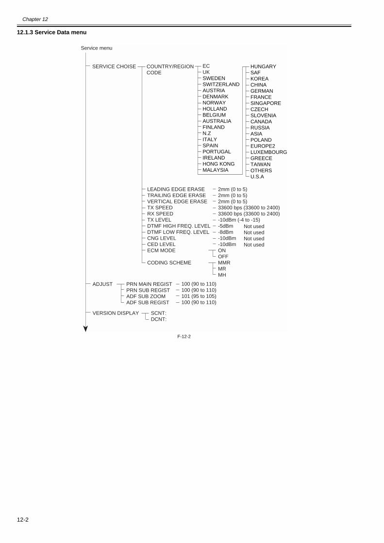
Chapter 12
12-2
12.1.3 Service Data menu0018-5011
F-12-2
ADJUST PRN MAIN REGISTPRN SUB REGISTADF SUB ZOOMADF SUB REGIST
VERSION DISPLAY SCNT:DCNT:
100 (90 to 110)100 (90 to 110)101 (95 to 105)100 (90 to 110)
SERVICE CHOISE COUNTRY/REGIONCODE
LEADING EDGE ERASETRAILING EDGE ERASEVERTICAL EDGE ERASETX SPEEDRX SPEEDTX LEVELDTMF HIGH FREQ. LEVELDTMF LOW FREQ. LEVELCNG LEVELCED LEVELECM MODE
CODING SCHEME
2mm (0 to 5)2mm (0 to 5)2mm (0 to 5)33600 bps (33600 to 2400)33600 bps (33600 to 2400)-10dBm (-4 to -15)-5dBm-8dBm-10dBm-10dBmONOFFMMRMRMH
Not usedNot usedNot usedNot used
ECUKSWEDENSWITZERLANDAUSTRIADENMARKNORWAYHOLLANDBELGIUMAUSTRALIAFINLANDN.ZITALYSPAINPORTUGALIRELANDHONG KONGMALAYSIA
HUNGARYSAFKOREACHINAGERMANFRANCESINGAPORECZECHSLOVENIACANADARUSSIAASIAPOLANDEUROPE2LUXEMBOURGGREECETAIWANOTHERSU.S.A
Service menu
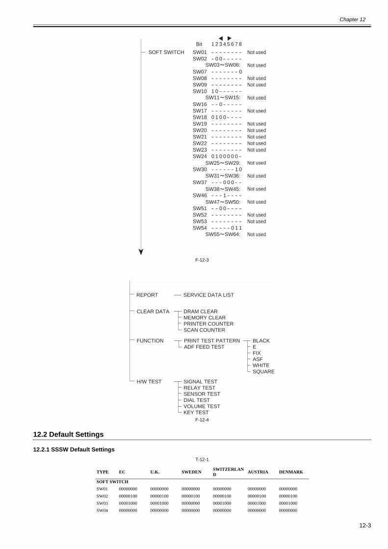
Chapter 12
12-3
F-12-3
F-12-4
12.2 Default Settings
12.2.1 SSSW Default Settings0018-5012
T-12-1
TYPE EC U.K. SWEDEN SWITZERLAND AUSTRIA DENMARK
SOFT SWITCHSW01 00000000 00000000 00000000 00000000 00000000 00000000SW02 00000100 00000100 00000100 00000100 00000100 00000100SW03 00001000 00001000 00000000 00001000 00001000 00001000SW04 00000000 00000000 00000000 00000000 00000000 00000000
SOFT SWITCH
Bit
Not used
Not used
Not usedNot used
Not used
Not used
Not usedNot usedNot usedNot usedNot used
Not used
Not used
Not used
Not used
Not usedNot used
Not used
1 2 3 4 5 6 7 8
SW01SW02
SW07SW08SW09SW10
SW16SW17SW18SW19SW20SW21SW22SW23SW24
SW30
SW37
SW46
SW51SW52SW53SW54
- - - - - - - -- 0 0 - - - - -
- - - - - - - 0- - - - - - - -- - - - - - - -1 0 - - - - - -
- - 0 - - - - -- - - - - - - -0 1 0 0 - - - -- - - - - - - -- - - - - - - -- - - - - - - -- - - - - - - -- - - - - - - -0 1 0 0 0 0 0 -
- - - - - - 1 0
- - - 0 0 0 - -
- - - 1 - - - -
- - 0 0 - - - -- - - - - - - -- - - - - - - -- - - - - 0 1 1
SW55 SW64:
SW03 SW06:
SW11 SW15:
SW25 SW29:
SW31 SW36:
SW38 SW45:
SW47 SW50:
CLEAR DATA DRAM CLEARMEMORY CLEARPRINTER COUNTERSCAN COUNTER
H/W TEST SIGNAL TESTRELAY TESTSENSOR TESTDIAL TESTVOLUME TESTKEY TEST
FUNCTION PRINT TEST PATTERNADF FEED TEST
BLACKEFIXASFWHITESQUARE
REPORT SERVICE DATA LIST
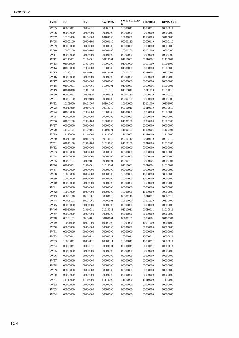
Chapter 12
12-4
SW05 00000011 00000011 00001011 10000011 10000011 00000011SW06 00000000 00000000 00000000 00000000 00000000 00000000SW07 10100000 10100000 10100000 10100000 10100000 10100000SW08 00000100 00000100 00000110 00000110 00000110 00000110SW09 00000000 00000000 00000000 00000000 00000000 00000000SW10 10000100 10000100 10000100 10000100 10001100 10000100SW11 00000000 00000000 00000100 00000000 00000000 00000100SW12 00110001 01110001 00110001 01110001 01110001 01110001SW13 01001000 01001000 01001000 01001000 01001000 01001000SW14 01000000 01000000 01000000 01000000 01000000 01000000SW15 10110101 10110101 10110101 10110101 10110101 10110101SW16 00000000 00000000 00000000 00000000 00000000 00000000SW17 00000000 00000000 00000000 00000000 00000000 00000000SW18 01000001 01000001 01000001 01000001 01000001 01000001SW19 01011010 01011010 01011010 01011010 01011010 01011010SW20 00000011 00000110 00000111 00000110 00000110 00000110SW21 00000100 00000100 00000100 00000100 00000100 00000100SW22 10101000 10101000 10101000 10101000 10101000 10101000SW23 00010010 00010010 00010010 00010010 00010010 00010010SW24 01000000 01000000 01000000 01000000 01000000 01000000SW25 00000000 00100000 00000000 00000000 00000000 00000000SW26 01000100 01000100 01000100 01000100 01000100 01000100SW27 00000000 00000000 00000000 00000000 00000000 00000000SW28 11100101 11100101 11100101 11100101 11100001 11100101SW29 11110000 11110000 11110000 11110000 11110000 11110000SW30 00010110 10011010 00010110 00010110 00010110 00010110SW31 01010100 01010100 01010100 01010100 01010100 01010100SW32 00000000 00000000 00000000 00000000 00000000 00000000SW33 00000000 00000000 00000000 00000000 00000000 00000000SW34 00000000 00000000 00000000 00000000 00000000 00000000SW35 00000101 00000101 00000101 00000101 00000101 00000101SW36 01010001 01010001 01010001 01010001 01010001 01010001SW37 00000000 00000000 00000000 00000000 00000000 00000000SW38 10000000 10000000 10000000 10000000 10000000 10000000SW39 10000000 10000000 10000000 10000000 10000000 10000000SW40 00000000 00000000 00000000 00000000 00000000 00000000SW41 00000000 00000000 00000000 00000000 00000000 00000000SW42 10000000 10000000 10000000 10000000 10000000 10000000SW43 00000110 10101001 00000110 00000110 00010011 00000110SW44 00001101 10101001 00001101 10110000 00101110 10110000SW45 00000000 00000000 00000000 00000000 00000000 00000000SW46 01010010 01010011 01010011 01010011 01010011 01010011SW47 00000000 00000000 00000000 00000000 00000000 00000000SW48 00100101 00100101 00100101 00100101 00000101 00100101SW49 10001000 10001000 10001000 10001000 10001000 10001000SW50 00000000 00000000 00000000 00000000 00000000 00000000SW51 00000000 00000000 00000000 00000000 00000000 00000000
SW52 10000011 10000111 10000011 10000011 10000011 10000011
SW53 10000011 10000111 10000011 10000011 10000011 10000011
SW54 00000011 00000011 00000001 00000011 00000011 00000011
SW55 00000000 00000000 00000000 00000000 00000000 00000000
SW56 00000000 00000000 00000000 00000000 00000000 00000000
SW57 00000000 00000000 00000000 00000000 00000000 00000000
SW58 00000000 00000000 00000000 00000000 00000000 00000000
SW59 00000000 00000000 00000000 00000000 00000000 00000000
SW60 00000000 00000000 00000000 00000000 00000000 00000000
SW61 11110000 11110000 11110000 11110000 11110000 11110000
SW62 00000000 00000000 00000000 00000000 00000000 00000000
SW63 00000000 00000000 00000000 00000000 00000000 00000000
SW64 00000000 00000000 00000000 00000000 00000000 00000000
TYPE EC U.K. SWEDEN SWITZERLAND AUSTRIA DENMARK
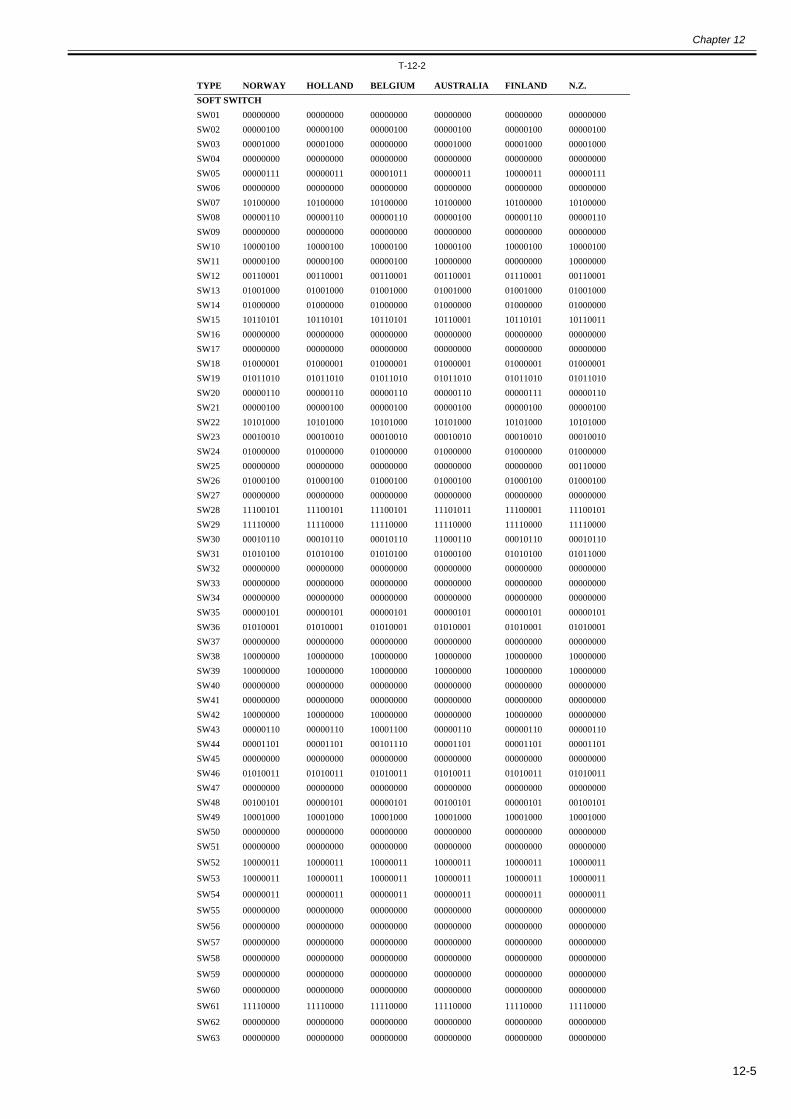
Chapter 12
12-5
T-12-2
TYPE NORWAY HOLLAND BELGIUM AUSTRALIA FINLAND N.Z.SOFT SWITCHSW01 00000000 00000000 00000000 00000000 00000000 00000000SW02 00000100 00000100 00000100 00000100 00000100 00000100SW03 00001000 00001000 00000000 00001000 00001000 00001000SW04 00000000 00000000 00000000 00000000 00000000 00000000SW05 00000111 00000011 00001011 00000011 10000011 00000111SW06 00000000 00000000 00000000 00000000 00000000 00000000SW07 10100000 10100000 10100000 10100000 10100000 10100000SW08 00000110 00000110 00000110 00000100 00000110 00000110SW09 00000000 00000000 00000000 00000000 00000000 00000000SW10 10000100 10000100 10000100 10000100 10000100 10000100SW11 00000100 00000100 00000100 10000000 00000000 10000000SW12 00110001 00110001 00110001 00110001 01110001 00110001SW13 01001000 01001000 01001000 01001000 01001000 01001000SW14 01000000 01000000 01000000 01000000 01000000 01000000SW15 10110101 10110101 10110101 10110001 10110101 10110011SW16 00000000 00000000 00000000 00000000 00000000 00000000SW17 00000000 00000000 00000000 00000000 00000000 00000000SW18 01000001 01000001 01000001 01000001 01000001 01000001SW19 01011010 01011010 01011010 01011010 01011010 01011010SW20 00000110 00000110 00000110 00000110 00000111 00000110SW21 00000100 00000100 00000100 00000100 00000100 00000100SW22 10101000 10101000 10101000 10101000 10101000 10101000SW23 00010010 00010010 00010010 00010010 00010010 00010010SW24 01000000 01000000 01000000 01000000 01000000 01000000SW25 00000000 00000000 00000000 00000000 00000000 00110000SW26 01000100 01000100 01000100 01000100 01000100 01000100SW27 00000000 00000000 00000000 00000000 00000000 00000000SW28 11100101 11100101 11100101 11101011 11100001 11100101SW29 11110000 11110000 11110000 11110000 11110000 11110000SW30 00010110 00010110 00010110 11000110 00010110 00010110SW31 01010100 01010100 01010100 01000100 01010100 01011000SW32 00000000 00000000 00000000 00000000 00000000 00000000SW33 00000000 00000000 00000000 00000000 00000000 00000000SW34 00000000 00000000 00000000 00000000 00000000 00000000SW35 00000101 00000101 00000101 00000101 00000101 00000101SW36 01010001 01010001 01010001 01010001 01010001 01010001SW37 00000000 00000000 00000000 00000000 00000000 00000000SW38 10000000 10000000 10000000 10000000 10000000 10000000SW39 10000000 10000000 10000000 10000000 10000000 10000000SW40 00000000 00000000 00000000 00000000 00000000 00000000SW41 00000000 00000000 00000000 00000000 00000000 00000000SW42 10000000 10000000 10000000 00000000 10000000 00000000SW43 00000110 00000110 10001100 00000110 00000110 00000110SW44 00001101 00001101 00101110 00001101 00001101 00001101SW45 00000000 00000000 00000000 00000000 00000000 00000000SW46 01010011 01010011 01010011 01010011 01010011 01010011SW47 00000000 00000000 00000000 00000000 00000000 00000000SW48 00100101 00000101 00000101 00100101 00000101 00100101SW49 10001000 10001000 10001000 10001000 10001000 10001000SW50 00000000 00000000 00000000 00000000 00000000 00000000SW51 00000000 00000000 00000000 00000000 00000000 00000000
SW52 10000011 10000011 10000011 10000011 10000011 10000011
SW53 10000011 10000011 10000011 10000011 10000011 10000011
SW54 00000011 00000011 00000011 00000011 00000011 00000011
SW55 00000000 00000000 00000000 00000000 00000000 00000000
SW56 00000000 00000000 00000000 00000000 00000000 00000000
SW57 00000000 00000000 00000000 00000000 00000000 00000000
SW58 00000000 00000000 00000000 00000000 00000000 00000000
SW59 00000000 00000000 00000000 00000000 00000000 00000000
SW60 00000000 00000000 00000000 00000000 00000000 00000000
SW61 11110000 11110000 11110000 11110000 11110000 11110000
SW62 00000000 00000000 00000000 00000000 00000000 00000000
SW63 00000000 00000000 00000000 00000000 00000000 00000000
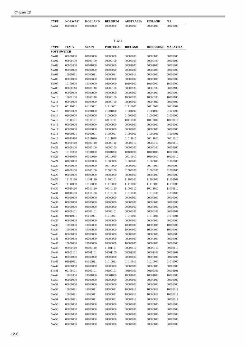
Chapter 12
12-6
T-12-3
SW64 00000000 00000000 00000000 00000000 00000000 00000000
TYPE ITALY SPAIN PORTUGAL IRELAND HONGKONG MALAYSIASOFT SWITCHSW01 00000000 00000000 00000000 00000000 00000000 00000000SW02 00000100 00000100 00000100 00000100 00000100 00000100SW03 00001000 00001000 00000000 00001000 00001000 00001000SW04 00000000 00000000 00000000 00000000 00000000 00000000SW05 10000011 00000011 00000011 00000011 00000000 00000000SW06 00000000 00000000 00000000 00000000 00000000 00000000SW07 10100000 10100000 10100000 10100000 10100000 10100000SW08 00000110 00000110 00000100 00000100 00000100 00000100SW09 00000000 00000000 00000000 00000000 00000000 00000000SW10 10001100 10000110 10000100 10000100 10000100 10000100SW11 00000000 00000000 00000100 00000000 00000000 00000100SW12 00110001 01110001 01110001 01110001 00110001 00110001SW13 01001000 01001000 01001000 01001000 01001000 01001000SW14 01000000 01000000 01000000 01000000 01000000 01000000SW15 10110101 10110101 10110101 10110101 10110000 10110010SW16 00000000 00000000 00000000 00000000 00000000 00000000SW17 00000000 00000000 00000000 00000000 00000000 00000000SW18 01000001 01000001 01000001 01000001 01000001 01000001SW19 01011010 01011010 01011010 01011010 00011010 00011010SW20 00000110 00000110 00000110 00000110 00000110 00000110SW21 00000100 00000100 00000100 00000100 00000100 00000100SW22 10101000 10101000 10101000 10101000 10101000 10101000SW23 00010010 00010010 00010010 00010010 10100010 10100010SW24 01000000 01000000 01000000 01000000 01000000 01000000SW25 00000000 00000000 00010000 00000000 00010000 00000000SW26 01000100 01000100 01000100 01000100 01000100 01000100SW27 00000000 00000000 00000000 00000000 00000000 00000000SW28 11101110 11101110 11100101 11100101 11100001 11100101SW29 11110000 11110000 11110000 11110000 11110000 11110000SW30 00010110 00010110 00010110 11000110 10011010 11000110SW31 01010100 01010100 01010100 01010100 01010100 01010100SW32 00000000 00000000 00000000 00000000 00000000 00000000SW33 00000000 00000000 00000000 00000000 00000000 00000000SW34 00000000 00000000 00000000 00000000 00000000 00000000SW35 00000101 00000101 00000101 00000101 00000101 00000101SW36 01010001 01010001 01010001 01010001 01010001 01010001SW37 00000000 00000000 00000000 00000000 00000000 00000000SW38 10000000 10000000 10000000 10000000 10000000 10000000SW39 10000000 10000000 10000000 10000000 10000000 10000000SW40 00000000 00000000 00000000 00000000 00000000 00000000SW41 00000000 00000000 00000000 00000000 00000000 00000000SW42 10000000 10000000 10000000 10000000 00000000 00000000SW43 00000110 00000110 11101101 00000110 00000110 00000110SW44 00001101 00001101 00001100 00001101 00001101 00001101SW45 00000000 00000000 00000000 00000000 00000000 00000000SW46 01010011 01010011 01010011 01010011 01010000 01010000SW47 00000000 00000000 00000000 00000000 00000000 00000000SW48 00100101 00000101 00100101 00100101 00100101 00100101SW49 10001000 10001000 10001000 10001000 10001000 10001000SW50 00000000 00000000 00000000 00000000 00000000 00000000SW51 00000000 00000000 00000000 00000000 00000000 00000000
SW52 10000011 10000011 10000011 10000011 10000011 10000011
SW53 10000011 10000011 10000011 10000011 10000011 10000011
SW54 00000011 00000011 00000001 00000011 00000011 00000011
SW55 00000000 00000000 00000000 00000000 00000000 00000000
SW56 00000000 00000000 00000000 00000000 00000000 00000000
SW57 00000000 00000000 00000000 00000000 00000000 00000000
SW58 00000000 00000000 00000000 00000000 00000000 00000000
SW59 00000000 00000000 00000000 00000000 00000000 00000000
TYPE NORWAY HOLLAND BELGIUM AUSTRALIA FINLAND N.Z.
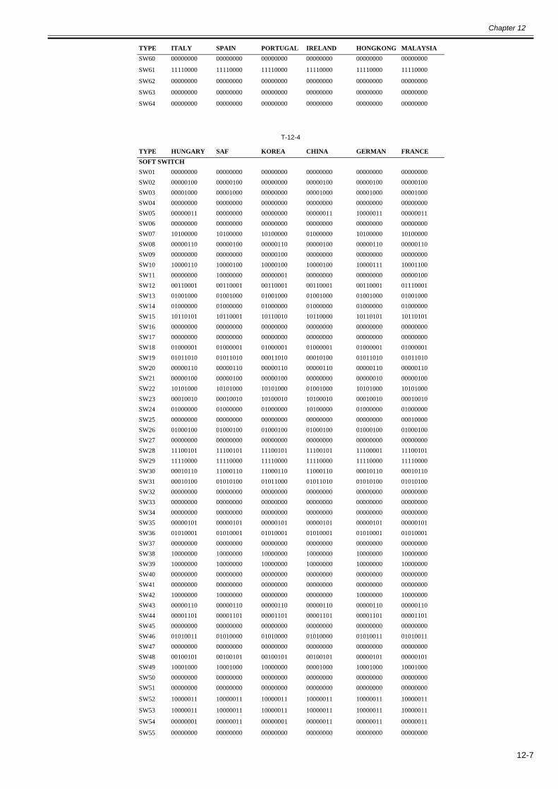
Chapter 12
12-7
T-12-4
SW60 00000000 00000000 00000000 00000000 00000000 00000000
SW61 11110000 11110000 11110000 11110000 11110000 11110000
SW62 00000000 00000000 00000000 00000000 00000000 00000000
SW63 00000000 00000000 00000000 00000000 00000000 00000000
SW64 00000000 00000000 00000000 00000000 00000000 00000000
TYPE HUNGARY SAF KOREA CHINA GERMAN FRANCESOFT SWITCHSW01 00000000 00000000 00000000 00000000 00000000 00000000SW02 00000100 00000100 00000000 00000100 00000100 00000100SW03 00001000 00001000 00000000 00001000 00001000 00001000SW04 00000000 00000000 00000000 00000000 00000000 00000000SW05 00000011 00000000 00000000 00000011 10000011 00000011SW06 00000000 00000000 00000000 00000000 00000000 00000000SW07 10100000 10100000 10100000 01000000 10100000 10100000SW08 00000110 00000100 00000110 00000100 00000110 00000110SW09 00000000 00000000 00000100 00000000 00000000 00000000SW10 10000110 10000100 10000100 10000100 10000111 10001100SW11 00000000 10000000 00000001 00000000 00000000 00000100SW12 00110001 00110001 00110001 00110001 00110001 01110001SW13 01001000 01001000 01001000 01001000 01001000 01001000SW14 01000000 01000000 01000000 01000000 01000000 01000000SW15 10110101 10110001 10110010 10110000 10110101 10110101SW16 00000000 00000000 00000000 00000000 00000000 00000000SW17 00000000 00000000 00000000 00000000 00000000 00000000SW18 01000001 01000001 01000001 01000001 01000001 01000001SW19 01011010 01011010 00011010 00010100 01011010 01011010SW20 00000110 00000110 00000110 00000110 00000110 00000110SW21 00000100 00000100 00000100 00000000 00000010 00000100SW22 10101000 10101000 10101000 01001000 10101000 10101000SW23 00010010 00010010 10100010 10100010 00010010 00010010SW24 01000000 01000000 01000000 10100000 01000000 01000000SW25 00000000 00000000 00000000 00000000 00000000 00010000SW26 01000100 01000100 01000100 01000100 01000100 01000100SW27 00000000 00000000 00000000 00000000 00000000 00000000SW28 11100101 11100101 11100101 11100101 11100001 11100101SW29 11110000 11110000 11110000 11110000 11110000 11110000SW30 00010110 11000110 11000110 11000110 00010110 00010110SW31 00010100 01010100 01011000 01011010 01010100 01010100SW32 00000000 00000000 00000000 00000000 00000000 00000000SW33 00000000 00000000 00000000 00000000 00000000 00000000SW34 00000000 00000000 00000000 00000000 00000000 00000000SW35 00000101 00000101 00000101 00000101 00000101 00000101SW36 01010001 01010001 01010001 01010001 01010001 01010001SW37 00000000 00000000 00000000 00000000 00000000 00000000SW38 10000000 10000000 10000000 10000000 10000000 10000000SW39 10000000 10000000 10000000 10000000 10000000 10000000SW40 00000000 00000000 00000000 00000000 00000000 00000000SW41 00000000 00000000 00000000 00000000 00000000 00000000SW42 10000000 10000000 00000000 00000000 10000000 10000000SW43 00000110 00000110 00000110 00000110 00000110 00000110SW44 00001101 00001101 00001101 00001101 00001101 00001101SW45 00000000 00000000 00000000 00000000 00000000 00000000SW46 01010011 01010000 01010000 01010000 01010011 01010011SW47 00000000 00000000 00000000 00000000 00000000 00000000SW48 00100101 00100101 00100101 00100101 00000101 00000101SW49 10001000 10001000 10000000 00001000 10001000 10001000SW50 00000000 00000000 00000000 00000000 00000000 00000000SW51 00000000 00000000 00000000 00000000 00000000 00000000
SW52 10000011 10000011 10000011 10000011 10000011 10000011
SW53 10000011 10000011 10000011 10000011 10000011 10000011
SW54 00000001 00000011 00000001 00000011 00000011 00000011
SW55 00000000 00000000 00000000 00000000 00000000 00000000
TYPE ITALY SPAIN PORTUGAL IRELAND HONGKONG MALAYSIA
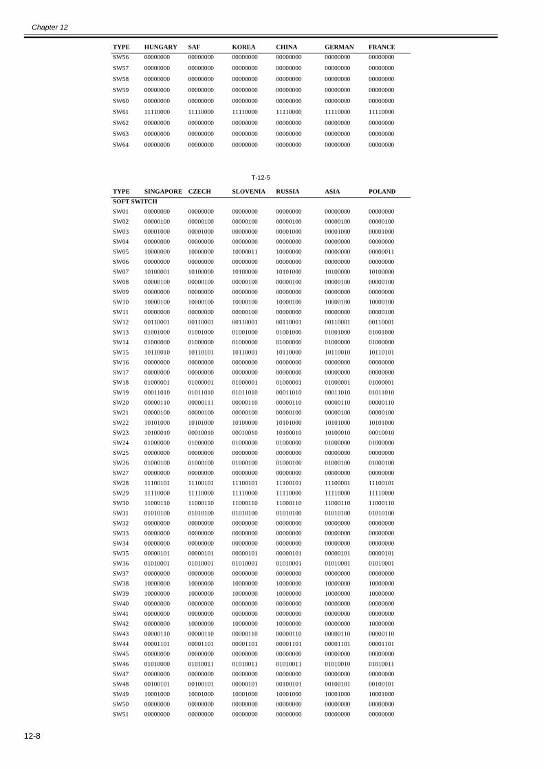
Chapter 12
12-8
T-12-5
SW56 00000000 00000000 00000000 00000000 00000000 00000000
SW57 00000000 00000000 00000000 00000000 00000000 00000000
SW58 00000000 00000000 00000000 00000000 00000000 00000000
SW59 00000000 00000000 00000000 00000000 00000000 00000000
SW60 00000000 00000000 00000000 00000000 00000000 00000000
SW61 11110000 11110000 11110000 11110000 11110000 11110000
SW62 00000000 00000000 00000000 00000000 00000000 00000000
SW63 00000000 00000000 00000000 00000000 00000000 00000000
SW64 00000000 00000000 00000000 00000000 00000000 00000000
TYPE SINGAPORE CZECH SLOVENIA RUSSIA ASIA POLANDSOFT SWITCHSW01 00000000 00000000 00000000 00000000 00000000 00000000SW02 00000100 00000100 00000100 00000100 00000100 00000100SW03 00001000 00001000 00000000 00001000 00001000 00001000SW04 00000000 00000000 00000000 00000000 00000000 00000000SW05 10000000 10000000 10000011 10000000 00000000 00000011SW06 00000000 00000000 00000000 00000000 00000000 00000000SW07 10100001 10100000 10100000 10101000 10100000 10100000SW08 00000100 00000100 00000100 00000100 00000100 00000100SW09 00000000 00000000 00000000 00000000 00000000 00000000SW10 10000100 10000100 10000100 10000100 10000100 10000100SW11 00000000 00000000 00000100 00000000 00000000 00000100SW12 00110001 00110001 00110001 00110001 00110001 00110001SW13 01001000 01001000 01001000 01001000 01001000 01001000SW14 01000000 01000000 01000000 01000000 01000000 01000000SW15 10110010 10110101 10110001 10110000 10110010 10110101SW16 00000000 00000000 00000000 00000000 00000000 00000000SW17 00000000 00000000 00000000 00000000 00000000 00000000SW18 01000001 01000001 01000001 01000001 01000001 01000001SW19 00011010 01011010 01011010 00011010 00011010 01011010SW20 00000110 00000111 00000110 00000110 00000110 00000110SW21 00000100 00000100 00000100 00000100 00000100 00000100SW22 10101000 10101000 10100000 10101000 10101000 10101000SW23 10100010 00010010 00010010 10100010 10100010 00010010SW24 01000000 01000000 01000000 01000000 01000000 01000000SW25 00000000 00000000 00000000 00000000 00000000 00000000SW26 01000100 01000100 01000100 01000100 01000100 01000100SW27 00000000 00000000 00000000 00000000 00000000 00000000SW28 11100101 11100101 11100101 11100101 11100001 11100101SW29 11110000 11110000 11110000 11110000 11110000 11110000SW30 11000110 11000110 11000110 11000110 11000110 11000110SW31 01010100 01010100 01010100 01010100 01010100 01010100SW32 00000000 00000000 00000000 00000000 00000000 00000000SW33 00000000 00000000 00000000 00000000 00000000 00000000SW34 00000000 00000000 00000000 00000000 00000000 00000000SW35 00000101 00000101 00000101 00000101 00000101 00000101SW36 01010001 01010001 01010001 01010001 01010001 01010001SW37 00000000 00000000 00000000 00000000 00000000 00000000SW38 10000000 10000000 10000000 10000000 10000000 10000000SW39 10000000 10000000 10000000 10000000 10000000 10000000SW40 00000000 00000000 00000000 00000000 00000000 00000000SW41 00000000 00000000 00000000 00000000 00000000 00000000SW42 00000000 10000000 10000000 10000000 00000000 10000000SW43 00000110 00000110 00000110 00000110 00000110 00000110SW44 00001101 00001101 00001101 00001101 00001101 00001101SW45 00000000 00000000 00000000 00000000 00000000 00000000SW46 01010000 01010011 01010011 01010011 01010010 01010011SW47 00000000 00000000 00000000 00000000 00000000 00000000SW48 00100101 00100101 00000101 00100101 00100101 00100101SW49 10001000 10001000 10001000 10001000 10001000 10001000SW50 00000000 00000000 00000000 00000000 00000000 00000000SW51 00000000 00000000 00000000 00000000 00000000 00000000
TYPE HUNGARY SAF KOREA CHINA GERMAN FRANCE
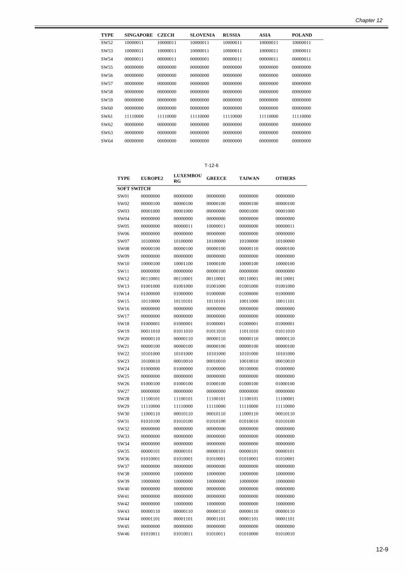
Chapter 12
12-9
T-12-6
SW52 10000011 10000011 10000011 10000011 10000011 10000011
SW53 10000011 10000011 10000011 10000011 10000011 10000011
SW54 00000011 00000011 00000001 00000011 00000011 00000011
SW55 00000000 00000000 00000000 00000000 00000000 00000000
SW56 00000000 00000000 00000000 00000000 00000000 00000000
SW57 00000000 00000000 00000000 00000000 00000000 00000000
SW58 00000000 00000000 00000000 00000000 00000000 00000000
SW59 00000000 00000000 00000000 00000000 00000000 00000000
SW60 00000000 00000000 00000000 00000000 00000000 00000000
SW61 11110000 11110000 11110000 11110000 11110000 11110000
SW62 00000000 00000000 00000000 00000000 00000000 00000000
SW63 00000000 00000000 00000000 00000000 00000000 00000000
SW64 00000000 00000000 00000000 00000000 00000000 00000000
TYPE EUROPE2 LUXEMBOURG GREECE TAIWAN OTHERS
SOFT SWITCHSW01 00000000 00000000 00000000 00000000 00000000SW02 00000100 00000100 00000100 00000100 00000100SW03 00001000 00001000 00000000 00001000 00001000SW04 00000000 00000000 00000000 00000000 00000000SW05 00000000 00000011 10000011 00000000 00000011SW06 00000000 00000000 00000000 00000000 00000000SW07 10100000 10100000 10100000 10100000 10100000SW08 00000100 00000100 00000100 00000110 00000100SW09 00000000 00000000 00000000 00000000 00000000SW10 10000100 10001100 10000100 10000100 10000100SW11 00000000 00000000 00000100 00000000 00000000SW12 00110001 00110001 00110001 00110001 00110001SW13 01001000 01001000 01001000 01001000 01001000SW14 01000000 01000000 01000000 01000000 01000000SW15 10110000 10110101 10110101 10011000 10011101SW16 00000000 00000000 00000000 00000000 00000000SW17 00000000 00000000 00000000 00000000 00000000SW18 01000001 01000001 01000001 01000001 01000001SW19 00011010 01011010 01011010 11011010 01011010SW20 00000110 00000110 00000110 00000110 00000110SW21 00000100 00000100 00000100 00000100 00000100SW22 10101000 10101000 10101000 10101000 10101000SW23 10100010 00010010 00010010 10010010 00010010SW24 01000000 01000000 01000000 00100000 01000000SW25 00000000 00000000 00000000 00000000 00000000SW26 01000100 01000100 01000100 01000100 01000100SW27 00000000 00000000 00000000 00000000 00000000SW28 11100101 11100101 11100101 11100101 11100001SW29 11110000 11110000 11110000 11110000 11110000SW30 11000110 00010110 00010110 11000110 00010110SW31 01010100 01010100 01010100 01010010 01010100SW32 00000000 00000000 00000000 00000000 00000000SW33 00000000 00000000 00000000 00000000 00000000SW34 00000000 00000000 00000000 00000000 00000000SW35 00000101 00000101 00000101 00000101 00000101SW36 01010001 01010001 01010001 01010001 01010001SW37 00000000 00000000 00000000 00000000 00000000SW38 10000000 10000000 10000000 10000000 10000000SW39 10000000 10000000 10000000 10000000 10000000SW40 00000000 00000000 00000000 00000000 00000000SW41 00000000 00000000 00000000 00000000 00000000SW42 00000000 10000000 10000000 00000000 10000000SW43 00000110 00000110 00000110 00000110 00000110SW44 00001101 00001101 00001101 00001101 00001101SW45 00000000 00000000 00000000 00000000 00000000SW46 01010011 01010011 01010011 01010000 01010010
TYPE SINGAPORE CZECH SLOVENIA RUSSIA ASIA POLAND
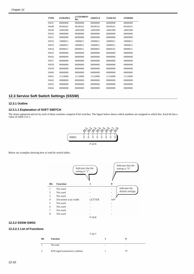
Chapter 12
12-10
12.3 Service Soft Switch Settings (SSSW)
12.3.1 Outline
12.3.1.1 Explanation of SOFT SWITCH0018-5013
The items registered and set by each of these switches comprise 8-bit switches. The figure below shows which numbers are assigned to which bits. Each bit has avalue of either 0 or 1.
F-12-5
Below are examples showing how to read bit switch tables.
F-12-6
12.3.2 SSSW-SW02:
12.3.2.1 List of Functions0018-5014
T-12-7
SW47 00000000 00000000 00000000 00000000 00000000SW48 00100101 00100101 00100101 00100101 00100101SW49 10001000 10001000 10001000 10001000 10001000SW50 00000000 00000000 00000000 00000000 00000000SW51 00000000 00000000 00000000 00000000 00000000
SW52 10000011 10000011 10000011 10000011 10000011
SW53 10000011 10000011 10000011 10000011 10000011
SW54 00000011 00000011 00000001 00000101 00000011
SW55 00000000 00000000 00000000 00000000 00000000
SW56 00000000 00000000 00000000 00000000 00000000
SW57 00000000 00000000 00000000 00000000 00000000
SW58 00000000 00000000 00000000 00000000 00000000
SW59 00000000 00000000 00000000 00000000 00000000
SW60 00000000 00000000 00000000 00000000 00000000
SW61 11110000 11110000 11110000 11110000 11110000
SW62 00000000 00000000 00000000 00000000 00000000
SW63 00000000 00000000 00000000 00000000 00000000
SW64 00000000 00000000 00000000 00000000 00000000
Bit Function 1 0
1 Not used - -
2 RTN signal transmission condition 1 0*
TYPE EUROPE2 LUXEMBOURG GREECE TAIWAN OTHERS
SW01 0 0 0 0 0 0 0 0
Bit 1
Bit 2
Bit 3
Bit 4
Bit 5
Bit 6
Bit 7
Bit 8
Not usedNot usedNot usedDocument scan widthNot usedNot usedNot usedNot used
---LETTER----
Function
12345678
Bit 1 0
Indicates that thesetting is "1".
Indicates thedefault settings.
Indicates that thesetting is "0".
---A4*----
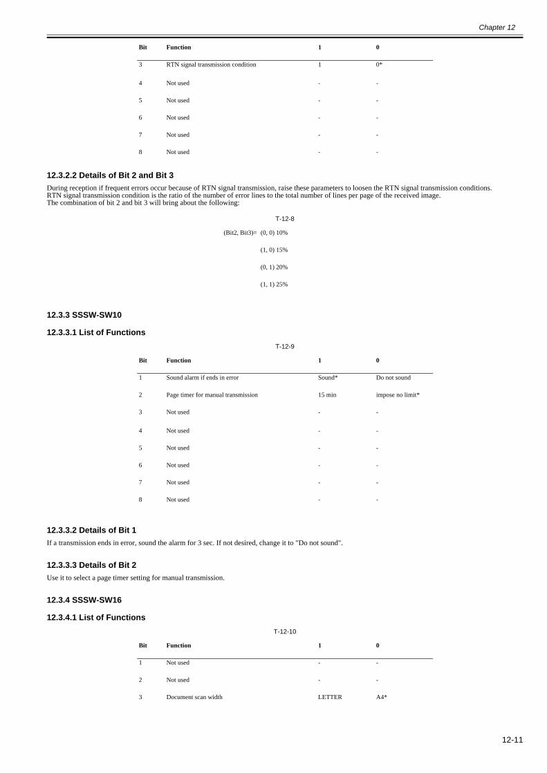
Chapter 12
12-11
12.3.2.2 Details of Bit 2 and Bit 30018-5015
During reception if frequent errors occur because of RTN signal transmission, raise these parameters to loosen the RTN signal transmission conditions.RTN signal transmission condition is the ratio of the number of error lines to the total number of lines per page of the received image.The combination of bit 2 and bit 3 will bring about the following:
T-12-8
12.3.3 SSSW-SW10
12.3.3.1 List of Functions0018-5016
T-12-9
12.3.3.2 Details of Bit 10018-5017
If a transmission ends in error, sound the alarm for 3 sec. If not desired, change it to "Do not sound".
12.3.3.3 Details of Bit 20018-5018
Use it to select a page timer setting for manual transmission.
12.3.4 SSSW-SW16
12.3.4.1 List of Functions0018-5019
T-12-10
3 RTN signal transmission condition 1 0*
4 Not used - -
5 Not used - -
6 Not used - -
7 Not used - -
8 Not used - -
(Bit2, Bit3)= (0, 0) 10%
(1, 0) 15%
(0, 1) 20%
(1, 1) 25%
Bit Function 1 0
1 Sound alarm if ends in error Sound* Do not sound
2 Page timer for manual transmission 15 min impose no limit*
3 Not used - -
4 Not used - -
5 Not used - -
6 Not used - -
7 Not used - -
8 Not used - -
Bit Function 1 0
1 Not used - -
2 Not used - -
3 Document scan width LETTER A4*
Bit Function 1 0
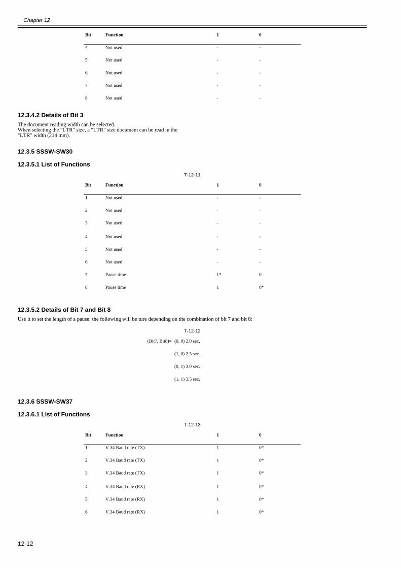
Chapter 12
12-12
12.3.4.2 Details of Bit 30018-5923
The document reading width can be selected.When selecting the "LTR" size, a "LTR" size document can be read in the"LTR" width (214 mm).
12.3.5 SSSW-SW30
12.3.5.1 List of Functions0018-5024
T-12-11
12.3.5.2 Details of Bit 7 and Bit 80018-5025
Use it to set the length of a pause; the following will be ture depending on the combination of bit 7 and bit 8:
T-12-12
12.3.6 SSSW-SW37
12.3.6.1 List of Functions0018-5026
T-12-13
4 Not used - -
5 Not used - -
6 Not used - -
7 Not used - -
8 Not used - -
Bit Function 1 0
1 Not used - -
2 Not used - -
3 Not used - -
4 Not used - -
5 Not used - -
6 Not used - -
7 Pause time 1* 0
8 Pause time 1 0*
(Bit7, Bit8)= (0, 0) 2.0 sec.
(1, 0) 2.5 sec.
(0, 1) 3.0 sec.
(1, 1) 3.5 sec.
Bit Function 1 0
1 V.34 Baud rate (TX) 1 0*
2 V.34 Baud rate (TX) 1 0*
3 V.34 Baud rate (TX) 1 0*
4 V.34 Baud rate (RX) 1 0*
5 V.34 Baud rate (RX) 1 0*
6 V.34 Baud rate (RX) 1 0*
Bit Function 1 0
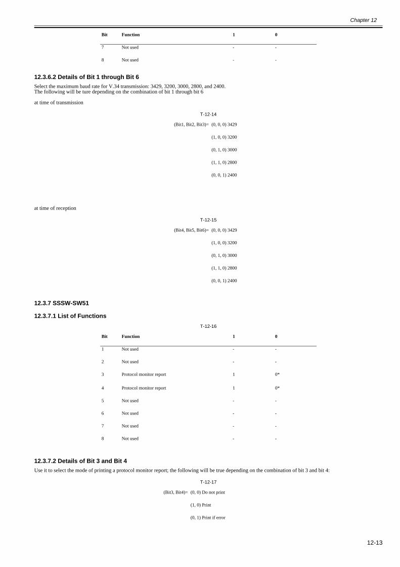
Chapter 12
12-13
12.3.6.2 Details of Bit 1 through Bit 60018-5027
Select the maximum baud rate for V.34 transmission: 3429, 3200, 3000, 2800, and 2400.The following will be ture depending on the combination of bit 1 through bit 6
at time of transmission
T-12-14
at time of reception
T-12-15
12.3.7 SSSW-SW51
12.3.7.1 List of Functions0018-5028
T-12-16
12.3.7.2 Details of Bit 3 and Bit 40018-5029
Use it to select the mode of printing a protocol monitor report; the following will be true depending on the combination of bit 3 and bit 4:
T-12-17
7 Not used - -
8 Not used - -
(Bit1, Bit2, Bit3)= (0, 0, 0) 3429
(1, 0, 0) 3200
(0, 1, 0) 3000
(1, 1, 0) 2800
(0, 0, 1) 2400
(Bit4, Bit5, Bit6)= (0, 0, 0) 3429
(1, 0, 0) 3200
(0, 1, 0) 3000
(1, 1, 0) 2800
(0, 0, 1) 2400
Bit Function 1 0
1 Not used - -
2 Not used - -
3 Protocol monitor report 1 0*
4 Protocol monitor report 1 0*
5 Not used - -
6 Not used - -
7 Not used - -
8 Not used - -
(Bit3, Bit4)= (0, 0) Do not print
(1, 0) Print
(0, 1) Print if error
Bit Function 1 0
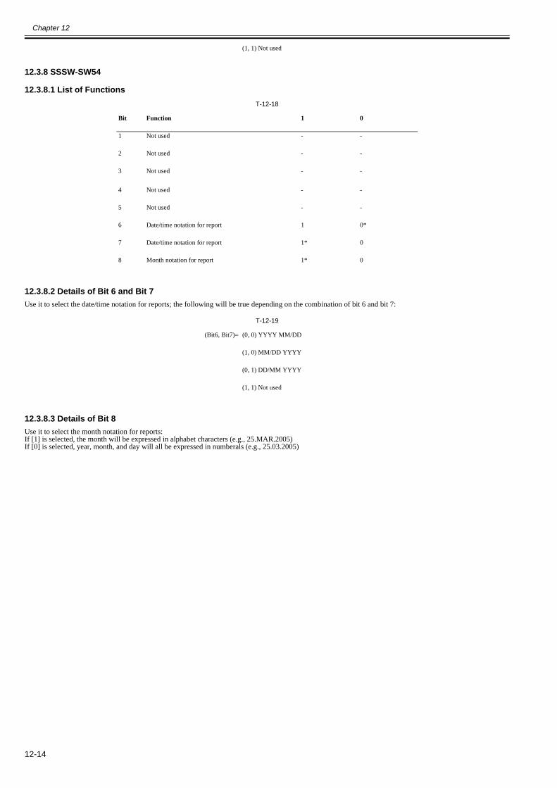
Chapter 12
12-14
12.3.8 SSSW-SW54
12.3.8.1 List of Functions0018-5925
T-12-18
12.3.8.2 Details of Bit 6 and Bit 70018-5031
Use it to select the date/time notation for reports; the following will be true depending on the combination of bit 6 and bit 7:
T-12-19
12.3.8.3 Details of Bit 80018-5032
Use it to select the month notation for reports:If [1] is selected, the month will be expressed in alphabet characters (e.g., 25.MAR.2005)If [0] is selected, year, month, and day will all be expressed in numberals (e.g., 25.03.2005)
(1, 1) Not used
Bit Function 1 0
1 Not used - -
2 Not used - -
3 Not used - -
4 Not used - -
5 Not used - -
6 Date/time notation for report 1 0*
7 Date/time notation for report 1* 0
8 Month notation for report 1* 0
(Bit6, Bit7)= (0, 0) YYYY MM/DD
(1, 0) MM/DD YYYY
(0, 1) DD/MM YYYY
(1, 1) Not used
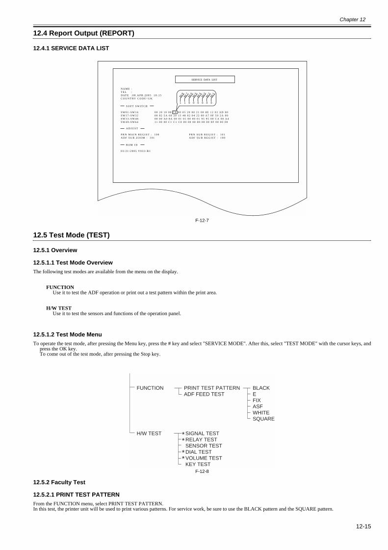
Chapter 12
12-15
12.4 Report Output (REPORT)
12.4.1 SERVICE DATA LIST0018-5033
F-12-7
12.5 Test Mode (TEST)
12.5.1 Overview
12.5.1.1 Test Mode Overview0018-5034
The following test modes are available from the menu on the display.
FUNCTIONUse it to test the ADF operation or print out a test pattern within the print area.
H/W TESTUse it to test the sensors and functions of the operation panel.
12.5.1.2 Test Mode Menu0018-5036
To operate the test mode, after pressing the Menu key, press the # key and select "SERVICE MODE". After this, select "TEST MODE" with the cursor keys, andpress the OK key.To come out of the test mode, after pressing the Stop key.
F-12-8
12.5.2 Faculty Test
12.5.2.1 PRINT TEST PATTERN0018-5037
From the FUNCTION menu, select PRINT TEST PATTERN.In this test, the printer unit will be used to print various patterns. For service work, be sure to use the BLACK pattern and the SQUARE pattern.
SERVICE DATA LIST
N A M E :T E L :D AT E : 0 8 . A P R . 2 0 0 5 1 8 : 1 5C O U N T RY C O D E = U K
S W 0 1 - S W 1 6S W 1 7 - S W 3 2S W 3 3 - S W 4 8S W 4 9 - S W 6 4
0 0 2 0 1 0 0 0 C 0 0 0 0 5 2 0 0 0 2 1 0 0 8 E 1 2 0 2 A D 0 00 0 8 2 5 A 6 0 2 0 1 5 4 8 0 2 0 4 2 2 0 0 A 7 0 F 5 9 2 A 0 00 0 0 0 A 0 8 A 0 0 0 1 0 1 0 0 0 0 0 1 9 5 9 5 0 0 C A 0 0 A 41 1 0 0 0 0 C 1 C 1 C 0 0 0 0 0 0 0 0 0 0 0 0 0 0 F 0 0 0 0 0 0
S O F T S W I T C H
P R N M A I N R E G I S T : 1 0 0A D F S U B Z O O M : 1 0 1
P R N S U B R E G I S T : 1 0 1A D F S U B R E G I S T : 1 0 0
A D J U S T
0 3 / 2 1 / 2 0 0 5 V 0 3 3 - B 1
R O M I D
1 1 0 0 0 0 0 0
Bit 8
Bit 7
Bit 6
Bit 5
Bit 4
Bit 3
Bit 2
Bit 1
H/W TEST SIGNAL TESTRELAY TESTSENSOR TESTDIAL TESTVOLUME TESTKEY TEST
FUNCTION PRINT TEST PATTERNADF FEED TEST
BLACKEFIXASFWHITESQUARE
**
**
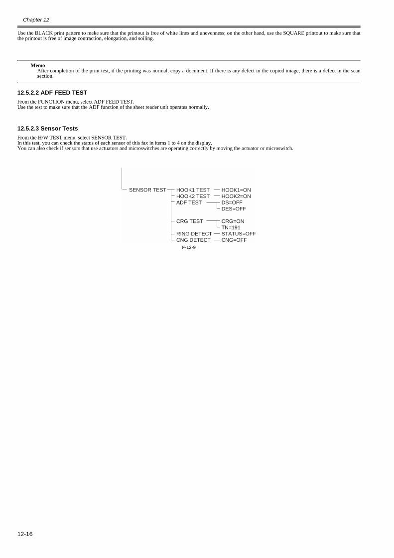
Chapter 12
12-16
Use the BLACK print pattern to meke sure that the printout is free of white lines and unevenness; on the other hand, use the SQUARE printout to make sure thatthe printout is free of image contraction, elongation, and soiling.
MemoAfter completion of the print test, if the printing was normal, copy a document. If there is any defect in the copied image, there is a defect in the scansection.
12.5.2.2 ADF FEED TEST0018-5038
From the FUNCTION menu, select ADF FEED TEST.Use the test to make sure that the ADF function of the sheet reader unit operates normally.
12.5.2.3 Sensor Tests0018-5039
From the H/W TEST menu, select SENSOR TEST.In this test, you can check the status of each sensor of this fax in items 1 to 4 on the display.You can also check if sensors that use actuators and microswitches are operating correctly by moving the actuator or microswitch.
F-12-9
SENSOR TEST HOOK1 TESTHOOK2 TESTADF TEST
CRG TEST
RING DETECTCNG DETECT
HOOK1=ONHOOK2=ONDS=OFFDES=OFF
CRG=ONTN=191STATUS=OFFCNG=OFF

Chapter 13 Service Tools


Contents
Contents
13.1 Service Tools..............................................................................................................................................................13-113.1.1 Solvent/Oil List ........................................................................................................................................................................ 13-1

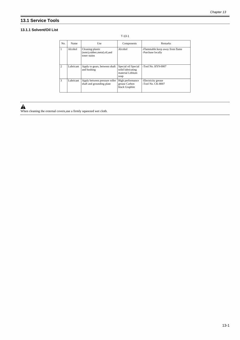
Chapter 13
13-1
13.1 Service Tools
13.1.1 Solvent/Oil List0018-5007
T-13-1
When cleaning the external covers,use a firmly squeezed wet cloth.
No. Name Use Components Remarks
1 Alcohol Cleaning:plastic (note),rubber,metal,oil,and toner stains
Alcohol -Flammable:keep away from flame-Purchase locally
2 Lubricant Apply to gears, between shaft and bushing
Special oil Special solid lubricating material Lithium soap
-Tool No. HY9-0007
3 Lubricant Apply between pressure roller shaft and grounding plate
High performance grease Carbon black Graphite
-Electricity grease-Tool No. CK-8007


Feb 6 2008