Embed Size (px)
Citation preview

L1® model II systemwith ToneMatch® port
Owner’s GuideBrugervejledningBedienungsanleitungGuía de usuarioNotice d’utilisationManuale di istruzioniGebruiksaanwijzingBruksanvisningen
Venice_FrontCover.fm Page 1 Friday, September 14, 2012 12:16 PM

EnglishDeutschFrançais DanskEspañolItalianoSvenska Nederlands DanskItalianoSvenska DeutschNederlands EnglishFrançais Español
VeniceOG.book Page 2 Friday, August 31, 2012 12:18 PM
SAFETY INFORMATION
Please read this owner’s guidePlease take the time to follow the instructions in this owner’s guide carefully. It will help you set up and operate your system properly and enjoy its advanced features. Please save this owner’s guide for future reference.
WARNING: To reduce the risk of fire or electrical shock, do not expose the system to rain or moisture.
WARNING: To reduce the risk of electric shock, do not disassemble this system unless you are qualified. Refer servicing to qualified service personnel.
The lightning flash with arrowhead symbol within an equilateral triangle alerts the user to the presence of uninsulated, dangerous voltage within the system enclosure that may be of sufficient magnitude to constitute a risk of electrical shock.
The exclamation point within an equilateral triangle, as marked on the system, is intended to alert the user to the presence of important operating and maintenance instructions in this owner’s guide.
CAUTION: This product shall be connected to a mains socket outlet with a protective earthing connection.
CAUTION: Make no modifications to the system or accessories. Unauthorized alterations may compromise safety, regulatory compliance, and system performance.
CAUTION: No naked flame sources, such as lighted candles, should be placed on the apparatus.
CAUTION: Where the mains plug is used as the disconnect device, such disconnect device shall remain readily operable.
Note: The product must be used indoors. It is neither designed nor tested for use outdoors, in recreation vehicles, or on boats.
This product conforms to all applicable EU requirements.The complete Declaration of Conformity can be found at: www.Bose.com/compliance.
Please complete for your records
Now is a good time to record the serial numbers of your system here and on your product registration card. You can register your product online at www.Bose.com/register or call (800) 905-1044. Failure to do so will not affect your warranty rights.
L1® model II power stand _______________________________________________________________________
L1 model II loudspeaker ________________________________________________________________________
B1/B2 bass module ____________________________________________________________________________
©2012 Bose Corporation. No part of this work may be reproduced, modified, distributed, or otherwise used without prior written permission.

English Deutsch FrançaisDansk Español Italiano SvenskaNederlandsDansk Italiano SvenskaDeutsch NederlandsEnglish FrançaisEspañol
VeniceOG.book Page 3 Friday, August 31, 2012 12:18 PM
IMPORTANT SAFETY INSTRUCTIONS
1. Read these instructions.
2. Keep these instructions.
3. Heed all warnings.
4. Follow all instructions.
5. Do not use this apparatus near water.
6. Clean only with a dry cloth.
7. Do not block any ventilation openings. Install in accordance with the manufacturer’s instruc-tions.
8. Do not install near any heat sources, such as radiators, heat registers, stoves, or other appa-ratus (including amplifiers) that produce heat.
9. Do not defeat the safety purpose of the polar-ized or grounding-type plug. A polarized plug has two blades with one wider than the other. A grounding-type plug has two blades and a third grounding prong. The wider blade or third prong is provided for your safety. If the provided plug does not fit into your outlet, consult an electri-cian for replacement of the obsolete outlet.
10. Protect the power cord from being walked on or pinched, particularly at plugs, convenience receptacles, and the point where they exit from the apparatus.
11. Only use attachments/accessories specified by the manufacturer.
12. Use only with the cart, stand, tripod, bracket, or table specified by the man-ufacturer or sold with the apparatus. When a cart is used, use caution when moving the cart/apparatus combination to avoid injury from tip-over.
13. Unplug this apparatus during lightning storms or when unused for long periods of time.
14. Refer all servicing to qualified service personnel. Servicing is required when the apparatus has been damaged in any way, such as power-supply cord or plug is damaged, liquid has been spilled or objects have fallen into the apparatus, the apparatus has been exposed to rain or moisture, does not operate normally, or has been dropped.
15. To prevent risk of fire or electric shock, avoid overloading wall outlets, extension cords, or integral convenience receptacles.
16. Do not let objects or liquids enter the product – as they may touch dangerous voltage points or short-circuit parts that could result in a fire or electric shock.
17. See product enclosure bottom for safety-related markings.
18. Use proper power sources – Plug the product into a proper power source, as described in the operating instructions or as marked on the product.
19. Apparatus shall not be exposed to dripping or splashing, and no objects filled with liquids, such as vases, shall be placed on the apparatus.
Information about products that generate electrical noiseNOTE: This equipment has been tested and found to comply with the limits for a Class A digital device, pursuant to part 15 of the FCC Rules.These limits are designed to provide reasonable protection against harmful interference when the equipment is operated in a commercial environment. This equipment generates, uses, and can radiate radio frequency energy and, if not installed and used in accordance with the instruction manual, may cause harmful interference to radio communications. Operation of this equipment in a residential area is likely to cause harmful interference in which case the user will be required to correct the interference at their own expense.
Changes or modifications not expressly approved by Bose Corporation could void the user's authority to operate this equipment.
This Class A digital apparatus complies with Canadian ICES-003.
Initial turn on inrush current: 32 Amps
Inrush current after AC mains interruption of 5 seconds: 32 Amps
This product meets all EN55103-2 immunity requirements for E2 electromagnetic environment.
Venice_SafetyInstructions.fm 8/12

4
EnglishDeutschFrançais DanskEspañolItalianoSvenska Nederlands DanskItalianoSvenska DeutschNederlands EnglishFrançais Español
INTRODUCTION 5Welcome . . . . . . . . . . . . . . . . . . . . . . . . . . . . . . . . . . . . . . . . . . . . . . . . . . . . . . . . . . . . . . . . . . . . . . . . . . . . . . . . . . . 5Features and benefits . . . . . . . . . . . . . . . . . . . . . . . . . . . . . . . . . . . . . . . . . . . . . . . . . . . . . . . . . . . . . . . . . . . . . . . . . 5Product overview . . . . . . . . . . . . . . . . . . . . . . . . . . . . . . . . . . . . . . . . . . . . . . . . . . . . . . . . . . . . . . . . . . . . . . . . . . . . . 6Connections and controls . . . . . . . . . . . . . . . . . . . . . . . . . . . . . . . . . . . . . . . . . . . . . . . . . . . . . . . . . . . . . . . . . . . . . . 7
SYSTEM SETUP 8Parts list . . . . . . . . . . . . . . . . . . . . . . . . . . . . . . . . . . . . . . . . . . . . . . . . . . . . . . . . . . . . . . . . . . . . . . . . . . . . . . . . . . . . 8Positioning your system . . . . . . . . . . . . . . . . . . . . . . . . . . . . . . . . . . . . . . . . . . . . . . . . . . . . . . . . . . . . . . . . . . . . . . . . 9Setting up the L1® model II power stand . . . . . . . . . . . . . . . . . . . . . . . . . . . . . . . . . . . . . . . . . . . . . . . . . . . . . . . . . . . 10Assembling the L1 model II top and bottom array loudspeakers . . . . . . . . . . . . . . . . . . . . . . . . . . . . . . . . . . . . . . . . 10Connecting to AC power . . . . . . . . . . . . . . . . . . . . . . . . . . . . . . . . . . . . . . . . . . . . . . . . . . . . . . . . . . . . . . . . . . . . . . . 11Connecting the B1 bass module . . . . . . . . . . . . . . . . . . . . . . . . . . . . . . . . . . . . . . . . . . . . . . . . . . . . . . . . . . . . . . . . . 12Adding a T1 ToneMatch® audio engine (optional) . . . . . . . . . . . . . . . . . . . . . . . . . . . . . . . . . . . . . . . . . . . . . . . . . . . . 13Adding a second B1 bass module (optional) . . . . . . . . . . . . . . . . . . . . . . . . . . . . . . . . . . . . . . . . . . . . . . . . . . . . . . . . 14Adding a PackLite® power amplifier model A1 (optional) . . . . . . . . . . . . . . . . . . . . . . . . . . . . . . . . . . . . . . . . . . . . . . . 15
Connecting multiple B1 bass modules . . . . . . . . . . . . . . . . . . . . . . . . . . . . . . . . . . . . . . . . . . . . . . . . . . . . . . . 15Connecting a second B2 module . . . . . . . . . . . . . . . . . . . . . . . . . . . . . . . . . . . . . . . . . . . . . . . . . . . . . . . . . . . . 16
OPERATING INFORMATION 17Setting the analog input level . . . . . . . . . . . . . . . . . . . . . . . . . . . . . . . . . . . . . . . . . . . . . . . . . . . . . . . . . . . . . . . . . . . . 17Using a T1 ToneMatch® audio engine and an analog input source . . . . . . . . . . . . . . . . . . . . . . . . . . . . . . . . . . . . . . . 17User scenarios . . . . . . . . . . . . . . . . . . . . . . . . . . . . . . . . . . . . . . . . . . . . . . . . . . . . . . . . . . . . . . . . . . . . . . . . . . . . . . . 17
Single musician . . . . . . . . . . . . . . . . . . . . . . . . . . . . . . . . . . . . . . . . . . . . . . . . . . . . . . . . . . . . . . . . . . . . . . . . . 17Multiple musicians . . . . . . . . . . . . . . . . . . . . . . . . . . . . . . . . . . . . . . . . . . . . . . . . . . . . . . . . . . . . . . . . . . . . . . . 18Full band . . . . . . . . . . . . . . . . . . . . . . . . . . . . . . . . . . . . . . . . . . . . . . . . . . . . . . . . . . . . . . . . . . . . . . . . . . . . . . . 19DJ events . . . . . . . . . . . . . . . . . . . . . . . . . . . . . . . . . . . . . . . . . . . . . . . . . . . . . . . . . . . . . . . . . . . . . . . . . . . . . . 20
CARE AND MAINTENANCE 21Caring for your product . . . . . . . . . . . . . . . . . . . . . . . . . . . . . . . . . . . . . . . . . . . . . . . . . . . . . . . . . . . . . . . . . . . . . . . . 21
Cleaning . . . . . . . . . . . . . . . . . . . . . . . . . . . . . . . . . . . . . . . . . . . . . . . . . . . . . . . . . . . . . . . . . . . . . . . . . . . . . . . 21Getting service . . . . . . . . . . . . . . . . . . . . . . . . . . . . . . . . . . . . . . . . . . . . . . . . . . . . . . . . . . . . . . . . . . . . . . . . . . 21
Troubleshooting . . . . . . . . . . . . . . . . . . . . . . . . . . . . . . . . . . . . . . . . . . . . . . . . . . . . . . . . . . . . . . . . . . . . . . . . . . . . . . 21Limited Warranty and Registration . . . . . . . . . . . . . . . . . . . . . . . . . . . . . . . . . . . . . . . . . . . . . . . . . . . . . . . . . . . . . . . . 23Accessories . . . . . . . . . . . . . . . . . . . . . . . . . . . . . . . . . . . . . . . . . . . . . . . . . . . . . . . . . . . . . . . . . . . . . . . . . . . . . . . . . 23Technical Information . . . . . . . . . . . . . . . . . . . . . . . . . . . . . . . . . . . . . . . . . . . . . . . . . . . . . . . . . . . . . . . . . . . . . . . . . . 23
Mechanical . . . . . . . . . . . . . . . . . . . . . . . . . . . . . . . . . . . . . . . . . . . . . . . . . . . . . . . . . . . . . . . . . . . . . . . . . . . . . 23Electrical . . . . . . . . . . . . . . . . . . . . . . . . . . . . . . . . . . . . . . . . . . . . . . . . . . . . . . . . . . . . . . . . . . . . . . . . . . . . . . . 23Audio Input/Output . . . . . . . . . . . . . . . . . . . . . . . . . . . . . . . . . . . . . . . . . . . . . . . . . . . . . . . . . . . . . . . . . . . . . . . 23
VeniceOG.book Page 4 Friday, August 31, 2012 12:18 PM

English Deutsch FrançaisDansk Español Italiano SvenskaNederlandsDansk Italiano SvenskaDeutsch NederlandsEnglish FrançaisEspañol
VeniceOG.book Page 5 Friday, August 31, 2012 12:18 PM
INTRODUCTION
WelcomeThank you for purchasing the Bose® L1® model II system with ToneMatch® port. Based on a revolutionary new technology, this system brings the benefits of an intimate acoustic concert to amplified performance.
This owner’s guide provides detailed setup and operating instructions for your L1 model II system and explains how to connect equipment to it.
For additional information on using this system, including tips, techniques, and frequently asked questions, please visit www.Bose.com/livesound on the Internet.
Features and benefits• You control the sound – Just as in an unamplified performance, you control the sound.
You will no longer wonder how you sound to your fellow musicians or to your audience because you will hear what they hear.
• Quick and easy setup – The L1 model II system is easy to carry and can be set up in min-utes, not hours. This frees you from the time-consuming and often frustrating effort required to properly set up conventional sound equipment.
• Dramatically improved performance – Compared to using conventional equipment, performance and enjoyment dramatically improve because the struggle to hear yourself and the other musicians is diminished.
• Creates excitement and emotion – Enhanced performance of the musicians creates the kind of excitement and emotion that is valued by music lovers.
• You hear what the audience hears – For the first time, musicians hear what their audiences hear and thus, are less likely to play at uncomfortable sound levels.
• The music is naturally dynamic – The softest to the most intense passages can be heard and enjoyed.
• Improves your appearance – There is less equipment on the stage and more room.
• Sound reproduction unlike before – Audience members report that the clarity and excitement that come from hearing the accurate reproduction of sound from eachinstrument, and from hearing the sound of each instrument in its position on stage(as opposed to mono or even stereo mix of all instruments), is unlike anything they have heard before in an amplified performance.
5Venice_Intro.fm 8/12
INTRODUCTION
EnglishDeutschFrançais DanskEspañolItalianoSvenska Nederlands DanskItalianoSvenska DeutschNederlands EnglishFrançais Español
VeniceOG.book Page 6 Friday, August 31, 2012 12:18 PM
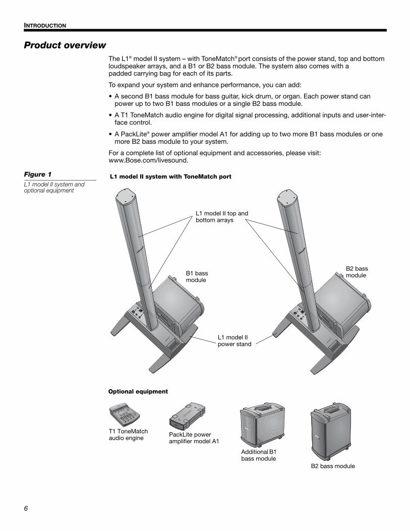
Product overviewThe L1® model II system – with ToneMatch® port consists of the power stand, top and bottom loudspeaker arrays, and a B1 or B2 bass module. The system also comes with a padded carrying bag for each of its parts.
To expand your system and enhance performance, you can add:
• A second B1 bass module for bass guitar, kick drum, or organ. Each power stand can power up to two B1 bass modules or a single B2 bass module.
• A T1 ToneMatch audio engine for digital signal processing, additional inputs and user-inter-face control.
• A PackLite® power amplifier model A1 for adding up to two more B1 bass modules or one more B2 bass module to your system.
For a complete list of optional equipment and accessories, please visit:www.Bose.com/livesound.
Figure 1L1 model II system and optional equipment
L1 model II top and bottom arrays
L1 model II power stand
L1 model II system with ToneMatch port
Optional equipment
B1 bass module
PackLite power amplifier model A1
T1 ToneMatch audio engine
Additional B1 bass module
B2 bass module
B2 bass module
6Venice_Intro.fm 8/12

INTRODUCTION
English Deutsch FrançaisDansk Español Italiano SvenskaNederlandsDansk Italiano SvenskaDeutsch NederlandsEnglish FrançaisEspañol
VeniceOG.book Page 7 Friday, August 31, 2012 12:18 PM
Connections and controlsThe top panel of the power stand provides system connectors and controls (Figure 2).
Figure 2Power stand top panel
Power switchSwitches the system on and off.
AC MainsAC power input connector.
Bass - Line OutPost-DSP bass signal output. Accepts a ¼" TRS phone cable. Used to drive a PackLite® power amplifier.
Bass Module OutBass output signal for driving one B2 or two B1 bass modules. Accepts a 4-wire bass module cable.
TrimAdjusts the level of the analog input signal.
ToneMatch® portDigital audio and power con-nection for the optional T1 ToneMatch audio engine. Accepts the included ToneMatch cable.
Analog InputA line-level analog input. Accepts a ¼" TRS phone cable. Used for an instrument or other audio source.
Signal/Clip LEDIndicates status of the analog input signal.
Green = normal inputYellow = input approaching clippingRed = input clipping
Power/Fault LEDIndicates power status.
Blue = system onRed = system fault
7Venice_Intro.fm 8/12

EnglishDeutschFrançais DanskEspañolItalianoSvenska Nederlands DanskItalianoSvenska DeutschNederlands EnglishFrançais Español
VeniceOG.book Page 8 Friday, August 31, 2012 12:18 PM
SYSTEM SETUP
Parts listThe L1® model II system is shipped in three cartons. Carefully unpack the cartons and check that you have all the items listed on this page.
WARNING: To avoid danger of suffocation, keep the plastic bags out of the reach of children.
Power stand carton Top and bottom array carton B1 or B2 bass module carton
L1 model II power stand
Carrying bag
AC power cord
Demonstration CD
Quick setup guide Owner’s guideL1TM Model II Systemwith ToneMatchTM port
Owner’s Guide
www.Bose.com/musicians
Product registration card
L1 model IITop and bottom loudspeaker arrays
Top
Bottom
Carrying bags
B1 or B2 bass module
Cover
Bass module cable (4-wire)
Adhesive rubber feet (for B2 only)
B1 or B2 bass module owner’s guide
B1Bass Module
Installation Guide
8

SYSTEM SETUP
English Deutsch FrançaisDansk Español Italiano SvenskaNederlandsDansk Italiano SvenskaDeutsch NederlandsEnglish FrançaisEspañol
VeniceOG.book Page 9 Friday, August 31, 2012 12:18 PM
Positioning your systemPlacing the power stand in the right location is an important part of setting up this product.
Determining the best location for your performance depends on several things.
• Size of staging area
• Number of performers
• Shared system (adding a T1 ToneMatch® audio engine and multiple instruments)
The following guidelines should get you started in setting up for a concert or show.
• Set up your system in the rear area of the performance stage.
• If possible, position your system behind the performer(s).
• If you are part of a group, avoid crowding together on stage. Allow some distance, ideally 7-8 feet (2.1-2.4 m), between you and the L1® model II system and another performer. This allows the sound to wrap around performers and reflect off adjacent surfaces of the room, creating a more pleasing room-filling sound.
Figure 1Placementrecommendations
Good
Better
Best
3 ft(0.9 m)
5 ft(1.5 m)
7-8 ft(2.1-2.4 m)
3 ft(0.9 m)
3 ft(0.9 m)
3 ft(0.9 m)
3 ft(0.9 m)
5 ft(1.5 m)
5 ft(1.5 m)
5 ft(1.5 m)
5 ft(1.5 m)
7-8 ft(2.1-2.4 m)
7-8 ft(2.1-2.4 m)
7-8 ft(2.1-2.4 m)
7-8 ft(2.1-2.4 m)
9
SYSTEM SETUP
EnglishDeutschFrançais DanskEspañolItalianoSvenska Nederlands DanskItalianoSvenska DeutschNederlands EnglishFrançais Español
VeniceOG.book Page 10 Friday, August 31, 2012 12:18 PM
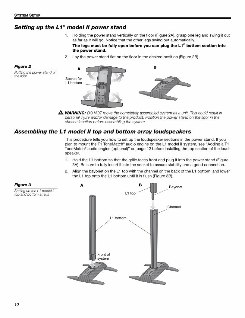
Setting up the L1® model II power stand1. Holding the power stand vertically on the floor (Figure 2A), grasp one leg and swing it out
as far as it will go. Notice that the other legs swing out automatically. The legs must be fully open before you can plug the L1® bottom section into the power stand.
2. Lay the power stand flat on the floor in the desired position (Figure 2B).
Figure 2Putting the power stand on the floor
A B
Socket for L1 bottom
WARNING: DO NOT move the completely assembled system as a unit. This could result in personal injury and/or damage to the product. Position the power stand on the floor in the chosen location before assembling the system.
Assembling the L1 model II top and bottom array loudspeakersThis procedure tells you how to set up the loudspeaker sections in the power stand. If you plan to mount the T1 ToneMatch® audio engine on the L1 model II system, see “Adding a T1 ToneMatch® audio engine (optional)” on page 12 before installing the top section of the loud-speaker.
1. Hold the L1 bottom so that the grille faces front and plug it into the power stand (Figure 3A). Be sure to fully insert it into the socket to assure stability and a good connection.
2. Align the bayonet on the L1 top with the channel on the back of the L1 bottom, and lower the L1 top onto the L1 bottom until it is flush (Figure 3B).
Figure 3Setting up the L1 model II top and bottom arrays L1 top
L1 bottom
Bayonet
Channel
A B
Front of system
10

SYSTEM SETUP
English Deutsch FrançaisDansk Español Italiano SvenskaNederlandsDansk Italiano SvenskaDeutsch NederlandsEnglish FrançaisEspañol
VeniceOG.book Page 11 Friday, August 31, 2012 12:18 PM
Connecting to AC power1. Make sure the power switch is off.
2. Plug one end of the AC power cord into the AC Mains connector on the power stand.
3. Plug the other end into a live AC (mains) receptacle (Figure 4).
Figure 4Power connections
AC Mains
CAUTION: DO NOT block or cover the handle opening, which is part of the ventilation system. Doing so can cause the L1® model II system to overheat, switch to a thermal protec-tion mode, and temporarily turn off.
Power switch
CAUTION: Bose recommends using a quality surge suppressor on all electronic equipment. Voltage variations and spikes can damage electronic components in any system. A quality suppressor, which can eliminate the vast majority of failures attributed to surges, may be pur-chased at electronics stores.
11

SYSTEM SETUP
EnglishDeutschFrançais DanskEspañolItalianoSvenska Nederlands DanskItalianoSvenska DeutschNederlands EnglishFrançais Español
VeniceOG.book Page 12 Friday, August 31, 2012 12:18 PM
Connecting the B1 bass moduleYou can place the B1 or B2 bass module either vertically or horizontally on the floor. It fits neatly between the legs of the power stand.
1. Plug one end of the B1 or B2 bass module cable into one of the bass connectors. Rotate the plug clockwise to lock it in place. You should hear a soft click as it locks.
2. Plug the other end of the cable into the Bass Module Out connector on the power stand. Rotate the plug clockwise to lock it.
Note: To disconnect a B1 or B2 cable, slide back the metal tab on the body of the plug, rotate the plug counterclockwise, and pull it out of the connector.
Figure 5B1 bass module
B1
Bass Module Out
Bass Module Out
B2
CAUTIONS:• DO NOT connect a B1 bass module to two power stands at the same time.
• DO NOT connect any bass module other than the B1 or B2 to the power stand.
• DO NOT substitute the supplied cable with a 2-wire speaker cable. Use only the supplied 4-wire cable to connect the bass module to the power stand. The power stand uses the signals on two of the wires (or the position of the B2 rear panel switch) to automatically sense how many bass modules are connected.
12

SYSTEM SETUP
English Deutsch FrançaisDansk Español Italiano SvenskaNederlandsDansk Italiano SvenskaDeutsch NederlandsEnglish FrançaisEspañol
VeniceOG.book Page 13 Friday, August 31, 2012 12:18 PM
Adding a T1 ToneMatch® audio engine (optional)The T1 ToneMatch® audio engine provides additional input/output capabilities to your system, plus digital signal processing to customize the way you sound. The audio engine comes with hardware for mounting it on the left or right side of the L1® model II top and bottom arrays.
Note: The audio engine mounts on the bottom section of the loudspeaker and requires removal of the top section before starting this procedure.
1. Slide the carriage into the channel on the rear of the L1 bottom and turn the knob clockwise to lock it in place (Figure 6).
2. Insert the mounting bar into the slot in the carriage and push it downward.
3. Place the T1 on the mounting bar as shown.
4. Plug one end of the ToneMatch cable (supplied with the audio engine) into the ToneMatch output port ( ) on the T1.
5. Using the hook and loop strap, secure the cable to the carriage.
6. Plug the other end of the cable into the ToneMatch port on the power stand.
Figure 6Mounting the T1
4
5
6
Carriage
Mounting bar
L1 model II bottom array
T1 ToneMatch audio engine
1
2
3
Locking knob
Power stand
Hook and loop strap
T1 ToneMatch audio engine
L1 model II bottom array
ToneMatch cable (supplied with T1)
13

SYSTEM SETUP
EnglishDeutschFrançais DanskEspañolItalianoSvenska Nederlands DanskItalianoSvenska DeutschNederlands EnglishFrançais Español
VeniceOG.book Page 14 Friday, August 31, 2012 12:18 PM
Adding a second B1 bass module (optional)The bass module output of the power stand can adequately drive one or two B1 bass modules. When placed horizontally, the modules are stackable (Figure 7).
One or two additional B1 modules can be added with the use of a PackLite® power amplifier. Refer to “Adding a PackLite® power amplifier model A1 (optional)” on page 15.
CAUTION: Do not connect more than two B1 bass modules to the Bass Module Out connector on the power stand. Driving more than two B1 bass modules from this outputimproperly loads the amplifier in the power stand, resulting in less than full system performance.
1. Connect the first B1 to the Bass Module Out connector on the power stand.
2. Plug one end of the second B1 cable into the unused connector of the first B1. Plug the other end of the cable into one of the connectors of the second B1.
Figure 7Installation of two B1 bass modules
Second B1 bass module cable
First B1 bass module cable
Bass Module Out
14

SYSTEM SETUP
English Deutsch FrançaisDansk Español Italiano SvenskaNederlandsDansk Italiano SvenskaDeutsch NederlandsEnglish FrançaisEspañol
VeniceOG.book Page 15 Friday, August 31, 2012 12:18 PM
Adding a PackLite® power amplifier model A1 (optional)
Connecting multiple B1 bass modulesUsing a PackLite® power amplifier model A1 allows you to add one or two additional B1 modules to your system. Refer to the A1 owner’s guide for detailed operating instructions.
1. Make sure the A1 amplifier power switch is OFF.
2. Plug one end of the supplied ¼" TRS cable into the Bass - Line Out connector on the power stand. Plug the other end into the INPUT connector on the A1 amplifier.
3. Connect a B1 bass module cable from the OUTPUT connector on the A1 to a B1 bass module. If desired, connect a second B1 to the first B1.
4. Plug one end of the AC power cord into the A1 amplifier and plug the other end into an AC (mains) outlet.
5. Switch the A1 power switch to ON (I).
Figure 8Connecting the A1 amplifier to the power stand
Additional B1 bass modules
Power stand
PackLite® power amplifier
Bass - Line Out
CAUTION: DO NOT stack more than four B1 modules in a column.
15

SYSTEM SETUP
EnglishDeutschFrançais DanskEspañolItalianoSvenska Nederlands DanskItalianoSvenska DeutschNederlands EnglishFrançais Español
VeniceOG.book Page 16 Friday, August 31, 2012 12:18 PM
Connecting a second B2 moduleUsing a PackLite® power amplifier model A1 allows you to add one additional B2 module to your L1 model II system.
1. Make sure the A1 amplifier power switch is OFF.
2. Plug one end of the supplied ¼" TRS cable into the Bass - Line Out connector on the power stand. Plug the other end into the INPUT connector on the A1 amplifier.
3. Connect a B2 bass module cable from the OUTPUT connector on the A1 to the B2 bass module.
4. Plug one end of the AC power cord into the A1 amplifier and plug the other end into an AC (mains) outlet.
5. Switch the A1 power switch to ON (I).
Figure 9Connecting two B2 bass modules
To power stand Bass Module Out
To PackLite amplifier OUTPUT
CAUTION: DO NOT stack more than two B2 modules.
16

English Deutsch FrançaisDansk Español Italiano SvenskaNederlandsDansk Italiano SvenskaDeutsch NederlandsEnglish FrançaisEspañol
VeniceOG.book Page 17 Friday, August 31, 2012 12:18 PM
OPERATING INFORMATION
Setting the analog input levelWhen connecting an audio source to the Analog Input, follow these steps to adjust the input Trim control.
1. Set the Trim control on the power stand to the 0 (zero) position.
2. Connect the audio source to the Analog Input.
3. Adjust the volume of the audio source to the desired level.
4. While playing the source, increase the Trim level until the Signal/Clip indicator glows green or yellow.
5. If the Signal/Clip indicator glows red, decrease the Trim level so that it glows only green or yellow.
Using a T1 ToneMatch® audio engine and an analog input sourceThe L1® model II system can operate with both a T1 ToneMatch® audio engine and an analog audio source connected to the power stand. However, keep in mind that the volume level of the audio engine and the analog audio source is adjusted independently.
• The power stand Trim control only affects the volume level of the analog audio source con-nected to the Analog Input. Therefore, the Signal/Clip indicator indicates the status only of the analog input signal.
• The T1 ToneMatch audio engine has a Trim control and signal/clip indicator for each input, a Volume control for each output channel, and a Master volume control that adjusts the level of the ToneMatch output sent to the power stand. These controls have no effect on the signal fed to the Analog Input.
User scenariosThere are many ways to set up and use this system with and without the T1 ToneMatch audio engine. The following pages show examples of some typical user scenarios. When using the T1 ToneMatch audio engine, refer to its owner’s guide for more information on setup and operation.
Single musicianA solo musician might play a single instrument through the L1 model II system (Figure 1). A solo musician also might play an instrument and use a microphone for vocals (Figure 2 on page 18).
Figure 1Single L1 model II system with keyboard
17

OPERATING INFORMATION
EnglishDeutschFrançais DanskEspañolItalianoSvenska Nederlands DanskItalianoSvenska DeutschNederlands EnglishFrançais Español
VeniceOG.book Page 18 Friday, August 31, 2012 12:18 PM
Figure 2
Single L1® model II system with guitar and microphone
T1 ToneMatch® audio engine
Multiple musiciansIn this scenario, a keyboard-guitar duo sings and plays through a single T1 ToneMatch audio engine and an L1 model II system.
Figure 3Single L1 model II system with multiple instruments and T1 ToneMatch audio engine
T1 ToneMatch audio engine
18

OPERATING INFORMATION
English Deutsch FrançaisDansk Español Italiano SvenskaNederlandsDansk Italiano SvenskaDeutsch NederlandsEnglish FrançaisEspañol
VeniceOG.book Page 19 Friday, August 31, 2012 12:18 PM
Full bandA full band scenario is built around multiple T1 ToneMatch® audio engines and L1® model II systems. Each musician plays and sings through a single T1 ToneMatch audio engine and L1 model II system.
Figure 4Multiple L1 model II systems, each with a T1 ToneMatch audio engine
T1 ToneMatch audio engine
T1 ToneMatch audio engine
T1 ToneMatchaudio engine
T1 ToneMatch audio engine
19

OPERATING INFORMATION
EnglishDeutschFrançais DanskEspañolItalianoSvenska Nederlands DanskItalianoSvenska DeutschNederlands EnglishFrançais Español
VeniceOG.book Page 20 Friday, August 31, 2012 12:18 PM
DJ eventsDJs use many types of input sources (CD player, turntable, MP3 player, etc.) plugged into a mixer. In this scenario, two mixer outputs can be fed into two L1® model II systems for stereo sound.
Figure 5Two L1 model II systems, a mixer, and input devices
20

English Deutsch FrançaisDansk Español Italiano SvenskaNederlandsDansk Italiano SvenskaDeutsch NederlandsEnglish FrançaisEspañol
VeniceOG.book Page 21 Friday, August 31, 2012 12:18 PM
CARE AND MAINTENANCE
Caring for your product
Cleaning• Clean the product enclosures using only a soft, dry cloth.
• Do not use any solvents, chemicals, or cleaning solutions containing alcohol, ammonia, or abrasives.
• Do not use any sprays near the product or allow liquids to spill into any openings.
• If necessary, you may carefully vacuum the grille of the L1® model II top and bottom loudspeaker arrays.
Getting serviceFor additional help in solving problems, contact Bose Live Music Product and Technical Support Team at (877) 335-2673 or visit our support area online at www.Bose.com/livesound.
TroubleshootingIf you experience problems while using this product, try the following solutions. If you still can’t solve the problem, please call the Bose Live Music Product and Technical Support Team direct at (877) 335-2673 to arrange for service.
Recommended troubleshooting tools
• Portable voltmeter • XLR and ¼" phone plug cables
• Cable tester • B1 bass module 4-wire cable
• AC outlet tester • Spare AC power cord
Problem What to do
System is plugged in, power switch is on, but power LED is off
• Make sure you have power at the AC outlet. Try operating a lamp or other equipment from the same AC outlet or test the outlet using an AC outlet tester.
• Make sure the power stand’s power cord plug is fully inserted into the AC outlet.
Power LED is on (green), but no sound
• Make sure volume control is turned up on your instrument.• Make sure the Trim level control is turned up on the power stand. • Make sure your instrument is plugged into the Analog Input jack. • Connect your instrument to the power stand using a different cable. • Plug your instrument into a different amplifier to make sure the instrument is working.
Power LED is red while the power stand is on
• Please call Bose Live Music Customer Support at (877) 335-2673 for assistance.
House circuit breaker keeps tripping
• If more than one power stand is plugged into the same AC circuit, stagger the turn-on times. Each power stand has an inrush current of about 32 amps when turned on.
• If you have more than three power stands plugged into a single 15 amp circuit, move some systems to another AC circuit. Each power stand can draw 5 amps or more when playing at high volumes for long periods of time.
21Venice_Care+Maint.fm 8/12

CARE AND MAINTENANCE
EnglishDeutschFrançais DanskEspañolItalianoSvenska Nederlands DanskItalianoSvenska DeutschNederlands EnglishFrançais Español
VeniceOG.book Page 22 Friday, August 31, 2012 12:18 PM
With nothing plugged into the power stand, a slight hum or buzz is heard
• Using an AC outlet tester, test the AC outlet that the power stand is plugged into for reversed or open (hot, neutral, and/or ground) contacts.
• If using an extension cord, make sure that the cord is also tested as above.
B1 or B2 bass module is plugged in, but no bass audio is heard
• Make sure you are using the included 4-wire bass module cable. • Make sure the bass module cable is plugged into the Bass Module Out connector and
the cable plug is fully engaged in the connector.• Try a different 4-wire cable. • If available, try a different bass module. • Make sure your power stand firmware is up to date.
B1 or B2 bass module sounds out of balance with the system
• Make sure you are using the bass module 4-wire cable included with the bass module package.
• Make sure that the bass module grille is facing forward toward the musicians andaudience.
No mid/high sounds heard from the L1® model II loudspeaker
• Make sure the L1 model II top and bottom arrays are firmly seated in their connectors.• Make sure connections are not bent or broken. • Try cleaning the contacts on the loudspeaker top and bottom with electronic contact
spray cleaner.
Instrument or audio source sounds distorted
• Make sure the Signal/Clip LED is not constantly red. If it is, lower the trim level.• Try a different source or instrument.• Try your source or instrument on another power stand.
Third-party-powered subwoofer sounds poor when connected to the Bass - Line Out connector on the power stand
• Unplug any Bose bass modules that may be connected to the power stand.• The signal from the Bass - Line Out may be too high for the powered subwoofer; try
attenuating the signal using commercially available direct boxes or in-line pad devices.• Try different connections to the third-party-powered subwoofer, such as balanced or
unbalanced cabling and/or a direct box.• Check that the gain and input controls on the third-party-powered subwoofer are set
appropriately. • If using a powered subwoofer with an adjustable crossover, set the crossover to 180Hz.
B1 or B2 bass modules powered by a third-party power amplifier and con-nected to the Bass - Line Out connector sounds poor
• Ensure that at least two B1 or B2 bass modules are directly connected to the Bass Module Out connector on the power stand using a bass module 4-wire cable.
• Check the gain settings on the third-party power amplifier. The volume level of the bass modules powered by the power stand should be similar to the bass modules powered by the external amplifier.
Microphone is encountering feedback
• Orient the microphone so that it is not pointing directly at its respective L1 model II top and bottom array loudspeaker.
• Try a different microphone.• Try a different position for the loudspeaker and/or vocalist on stage.• Increase the distance from the loudspeaker to the microphone.• If using a vocal effects processor, make sure it is not contributing to the feedback
problem.
Problem What to do
22Venice_Care+Maint.fm 8/12
CARE AND MAINTENANCE
English Deutsch FrançaisDansk Español Italiano SvenskaNederlandsDansk Italiano SvenskaDeutsch NederlandsEnglish FrançaisEspañol
VeniceOG.book Page 23 Friday, August 31, 2012 12:18 PM
Limited Warranty and RegistrationYour product is covered by a limited transferable warranty. Details of the warranty are provided with your product. Register your products online at www.Bose.com/register or call (800) 905-1044. Failure to do so will not affect your warranty rights.
AccessoriesVisit www.Bose.com/livesound, or call (800) 905-0886 for accessory information.
Technical Information
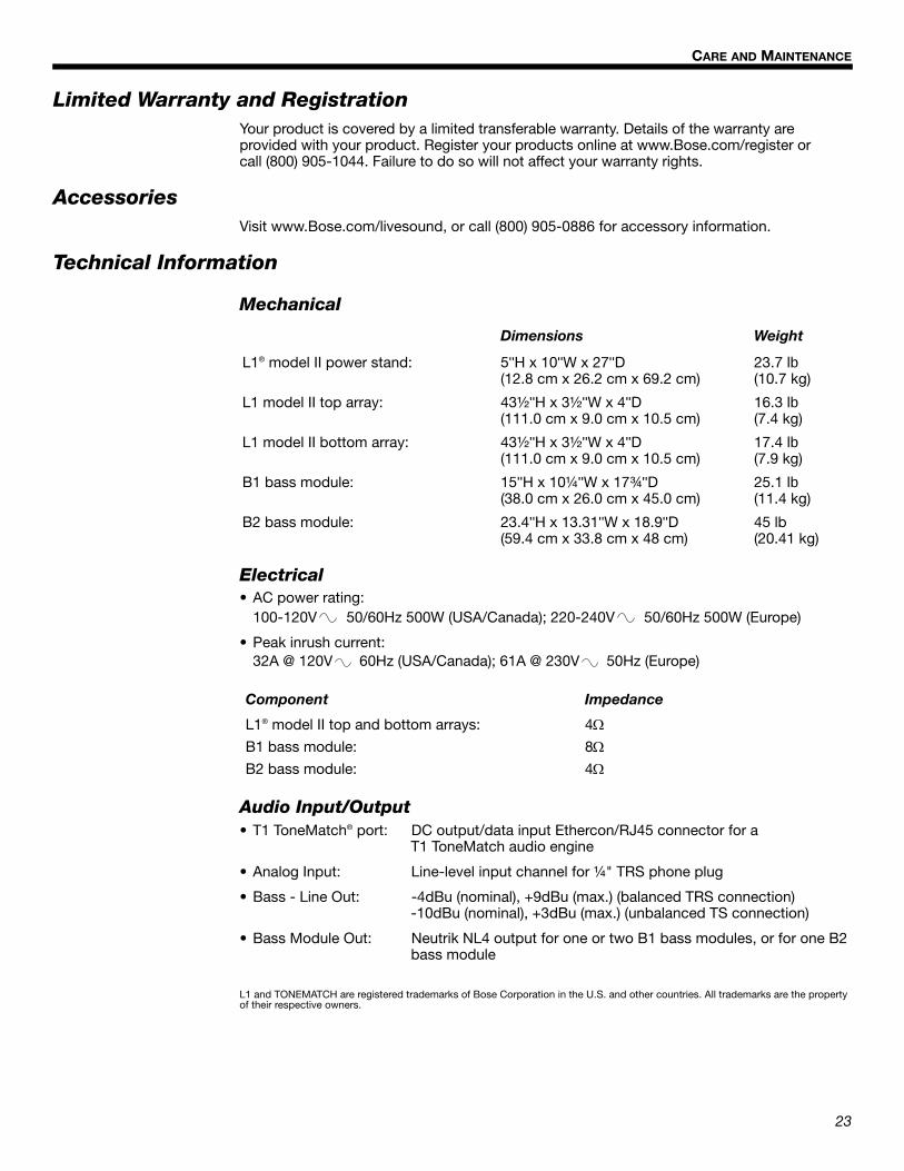
Mechanical
Dimensions Weight
L1® model II power stand: 5''H x 10''W x 27''D (12.8 cm x 26.2 cm x 69.2 cm)
23.7 lb (10.7 kg)
L1 model II top array: 43½''H x 3½''W x 4''D (111.0 cm x 9.0 cm x 10.5 cm)
16.3 lb (7.4 kg)
L1 model II bottom array: 43½''H x 3½''W x 4''D (111.0 cm x 9.0 cm x 10.5 cm)
17.4 lb (7.9 kg)
B1 bass module: 15''H x 10¼''W x 17¾''D (38.0 cm x 26.0 cm x 45.0 cm)
25.1 lb (11.4 kg)
B2 bass module: 23.4''H x 13.31''W x 18.9''D(59.4 cm x 33.8 cm x 48 cm)
45 lb(20.41 kg)
Electrical• AC power rating:
100-120V 50/60Hz 500W (USA/Canada); 220-240V 50/60Hz 500W (Europe)
• Peak inrush current: 32A @ 120V 60Hz (USA/Canada); 61A @ 230V 50Hz (Europe)
Component Impedance
L1® model II top and bottom arrays: 4B1 bass module: 8B2 bass module: 4
Audio Input/Output• T1 ToneMatch® port: DC output/data input Ethercon/RJ45 connector for a
T1 ToneMatch audio engine
• Analog Input: Line-level input channel for ¼" TRS phone plug
• Bass - Line Out: -4dBu (nominal), +9dBu (max.) (balanced TRS connection)-10dBu (nominal), +3dBu (max.) (unbalanced TS connection)
• Bass Module Out: Neutrik NL4 output for one or two B1 bass modules, or for one B2 bass module
L1 and TONEMATCH are registered trademarks of Bose Corporation in the U.S. and other countries. All trademarks are the property of their respective owners.
23Venice_Care+Maint.fm 8/12

©2012 Bose Corporation, The Mountain,Framingham, MA 01701-9168 USAAM356147 Rev.01
www.Bose.com/livesound
Venice_Back.fm Page 27 Friday, September 14, 2012 12:17 PM


![Horton Hears a Who! [2008]](https://img.pdfslide.us/doc/110x75/577c83da1a28abe054b68864/horton-hears-a-who-2008.jpg)