Embed Size (px)
Citation preview
Nov. 3, 1953 ` E. E, HUPP 2,657,701
FLUID CONTROL> VALVE
Filed May 21, 1949 . ‘ 2 sheets-sheet 1
_ _ /2 L0 /- 2.6 / .2.4
. u 26 // \ , _l_1_
l @Y 1 /6 /ô j 50 132%@
3F / ______ .. / “
È _ 22 (25 _
IN V EN TOR.
AT TOENE Y
2,657,701 Nov. 3, 1953 E. E. HUPP
FLUID CONTROL VALVE
2 Sheets-Sheet 2 Filed May 2l, 1949
INVENTOR.
EDM/fusor E. HUPP BY
ATTGENEY
Patented Nov. 3, 1953?»
UNITED STATES
2,657,71
ÈÀTEN'E‘ QFF'IC 2,357,701.Y
FLUID GONTROL VÑENE1
Edward'. E. Rupp', South Bend;y Ind». assignon- to: Bendix. AviationlGorp oratiorn,` South' Bend,ì Indm acorporation of- Delaware.
Application May‘ZI, 1949; SeriaîPNfo. 94";6'39’1i
(Cl. E37-L02), 17 Claims.
Thea present:l invention. relates. tu lluid’ control; mechanisms for.` controlling servofmo‘tors; oper ated. by' a differential: off fluid-I pressures. andi par.' ticularly to valves for theA control'. of vacuum. or' air' brake' systems for' automotive` vehicles;V
The' primary objectzof the present:v invention is; to provide-a control: valve'.whichY is .economia
cal to. manufacture;A efñcient; in. operationi,À simplei'n;constructienI.>
Afurther' object isto. provide a. hand. control vali/ef,~ which'. has ai minimum of: adjustment' con' trols possesses the. desired. degree- of sensi» tivit-y.v and:2 reliability' of; control; A still further' object. is= to'. furnis-h» a. reliable:
hand control' Valve havingz‘fewer' parts th‘ani similar valve heretofore-known. A still further objeot'is‘ to'. reducer.the'.tendency
of. a. controli Valve; to “horn-,W af..p'henomenonl ene countered ini fluid: controli valves which: o'b' serveil as sustained?vali/e.'cyclingzv
@ther` objects: of: the; invention and desirable» details of'Y construction'. ofi parts.:v will: become. ap'-i parent from‘. the iollowing.- detailed.' description of.' anL illustrative embodiment. oi? the.’ inventionì takenv in conjunctiom with'.y the: accompanying' drawings.` illustrating' said,ì embodimenaini Which-z.
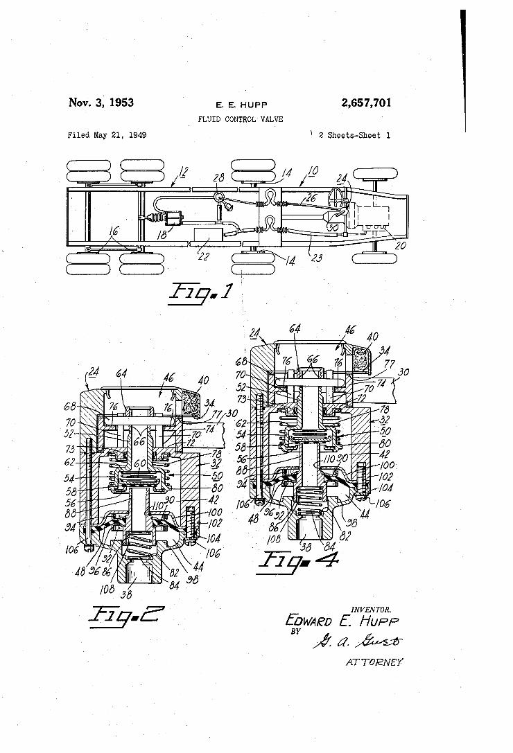
Figure-:1: is-iaschematic illustration.01’.atractor»v trailer vehicle, combination'A in. which. is\ utilizedg as a. part: ofi the; bra-kingi systenL. embodiment; ofv the'present'inventiom;
Figure'Z‘shaWs': amaxiali‘ section ofsîsaiid‘ embodi'». ment; in itsireleased or'oii‘ïposition;
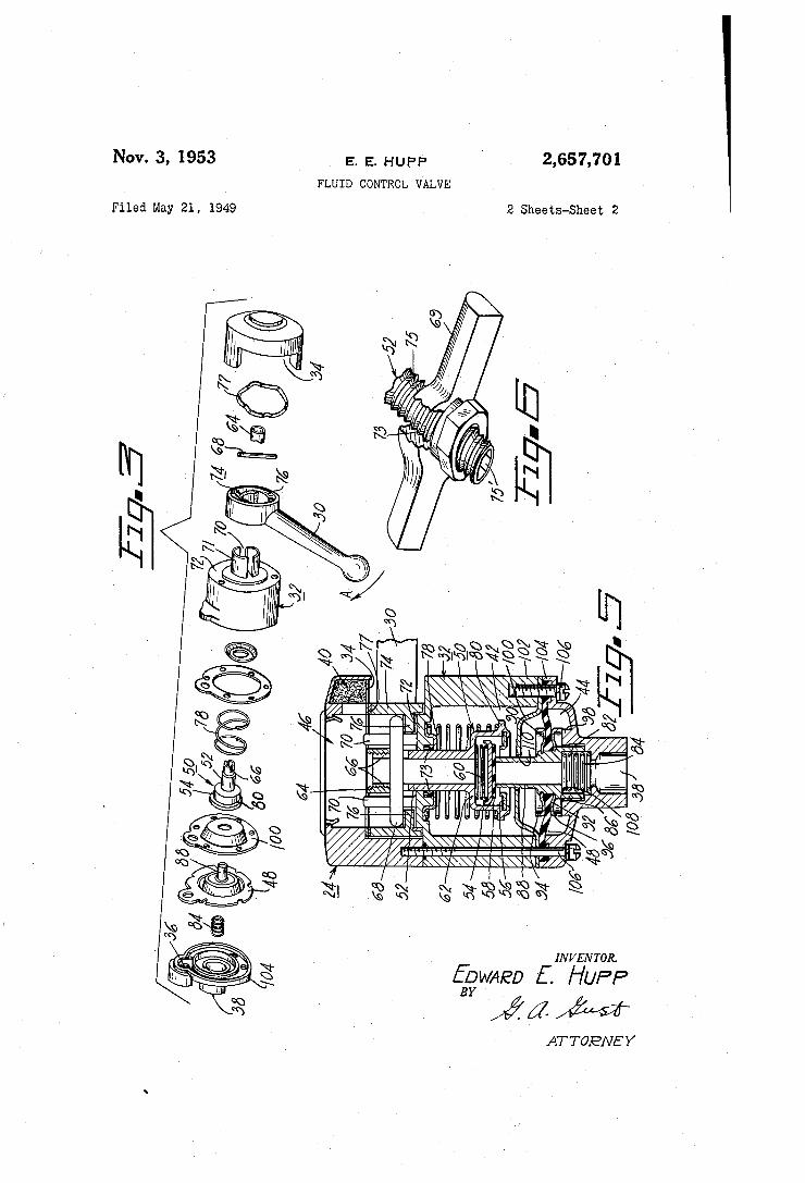
Figure f3 is: an exploded' viewsthereof; Figure 4 is similar to Figure 2 but with-thevalve
partsv shown', their: relative» positions.. immedi ately: after' an incrementalimovem‘entf.ofthe-hand; r lever in brake applying direction andi before the valve-partsr''haverlapped; Figure 5f isi a: similar View.' showing: the-.relative
positions ofthevaive' partsfor‘fully'opened cone` ditionyand; Y
Figure. 6: is;` an; illustration, partly.' sectioned; of.` another.` form; of valves adjustment andi actuating mechanism.
The. drawings"v and?, thee following' descr-ipti'enJ are directedLto an embodiment' ofthe-present? in» 'vention Whichïis intendedî for 'use-on a« combina@ tion; tractor-trailer' Velii’cleto ~ control» the" trailer' brakes. The» illustrated system¢ utilizes~ vacuumd suspend'edfï trailer' braláemotors; however, ít?'isîtb"
20.
l Ol
4011
2.. ben understood: tl'rani` thex control: valve: oí”- the‘presr ent.` invention may be usedito actuaire'other'types.v andzdesigns oftñuidzmotorsz
Referring: to: the dra-Wings anda more» particuif 1arlyto'Eîgure:lf~„the1reof, atractor Ißiandza'trailer |521 have,. respectively„ Wheel'. brakesf I4: and L‘S'l, brakes; lili' being.’ connectediby/means' of' tluidr. cone» nect'ions tol tlieé pmver'cylinden lfS= wliitzlnis` adapt- ed;a upon: actuation-,i to;v apply the said trailer'
»' brakes..
rllhe: manifold; Z'llr oñ the tractor' engine# is uti# lized. as ai vacuunn source; and; is;v connected; td~ a-y vacuumr tanki Z125 and: the“r power' cylinder It' by.I meansîof aicon‘duiliilîiil The: handi control1 waive~
v 2411er: thee present: invention is; connected; tov cen'-r duitLA 2aB: alsA a'. point' near.' theït manifold 2D; and; isi operatively connectedz to`r power cylinder: t8: by' means of controh line“v 2t?. Interposed' inf conduit 2% between valve: 24' andi power cylinder ißf and: connected'. withzthe vacuum' lineëZ'Ik ai valve' dee» vice.»28 whicln acts to accelerate'respo'nse‘tofthe` trailer: power cylinder'toul actuationz of‘. the: control’.
Eon purposes.z of:1 description;â the device' vali/ein; 28 will be considered merely a part of the: con-e»
v
Tihe‘:Í operator: oil` the tractor; ltr is:~ intended; to: manipulate-1 the controli valve 24= moving the: handlefß‘ l'ßithereof; toiregnlateitheamount ofibrafkf»V ing torquefdeliverableftoithetrailer. I 2f. The? control;l valîvef 24‘ provided with: a'. casing;
V32a 11a-ving: threerports 34;;35 (see-»Figure-Sì, and: BortJ 36sisiconneet’editb control line-ZegA porta'
3&‘ communicates: with. vacuum line » 2&1. and-L. port? 314s atsalli time'sf opens-.tn the atmosphere, theairï
s entering; the 'vali/fe,T 24: around?, handle' 30 to: pass through'airxcleaner 40, The valve 24 may.'ecriveniently;be:cazxnsideiedlY
as; being: divided; into.-Í three chambers; . a I control chamber 424,2, vacuumion ñuid chamberfêihan'dï an.; air> chamberrA'ßi. Ports'. dit; . 3:6;- and'LSäì' are; cnn- nectedi withi chambers: 46;. 42;. and; 4d“, respee‘f tivelyt'.. Thescontrolfchambenlmeîis separatedïfrom; vacuums chamber' 44'» by." ai'ñuidí responsive ele@ ment or. diaphragm Mh,v preferably-‘iabricatedî ot' rubber, . which: is suitablyf fastened;l to: the: casing 32'.. Thecontrol’. andivacuum: chambers-are op»l erativelyß sealedîfrom'ltlì'e air chamber "41îï'ïbyrneans oi’ji?ie'N air' t'ulìe`~ assembly-V or" device'L generally inf dicated by“ referencek numeralî 50i' Specifically; this assembly' 5w is1 composed cfa`A cylindricalï air'
5 tube or first pressure conducting member 52 hav ing a flared end 54 to which is secured an in wardly projecting annular flanged valve seat 55. A valve member or poppet 58 is carried inside flared end 54, and is urged into sealing engage ment with valve seat 56 by means of a resilient member such as the cylindrical shaped spring 5G which is compressed between the flared por tion 62 of tube 52 and valve member 5S. Air tube 52 is provided at its other end with
an open adjusting cap or nut B4 and diametric openings or slots 55 which may be varied in size by turning cap 54 for a purpose to be explained hereinafter. It is obvious that any element which can be adjustably moved to vary the size of said openings 66 may be used in place of the specific arrangement of the cap 64. Into openings 66 is inserted a cam follower or pin 68 which is guided for translatory axial movement with respect to the casing S2 in the slot 'ill formed in sleeve 1I (see Figure 3). This sleeve 1l which surrounds the upper end of tube 52 is preferably fixed in position with respect to casing 32 by being formed integral with the control chamber end wall 12 which surrounds air tube 52 in fluid tight rela tion by means of a rubber sealing ring i3. Ro tatably mounted on casing 32 is a cylindrically shaped cam member 14 having two oppositely disposed complementary cam surfaces 'l5 which are engaged by the ends of cam follower pin 53. . The air tube assembly 50 is at al1 times urged downwardly by means of a cylindrical compres sion spring 78 which encircles the lower end of air tube 52 to bear against end wall 12 and radial flange 80 on flared end 54 of the air tube 52. Thus, the upper edges of openings 65 are main tained in engagement with cam follower pin 65 to urge it against the cam surfaces '15. By turn ing the threaded cap or nut 65, the air tube as sembly can be raised or lowered with respect to the mouth of tube 88, this constituting the only adjustment necessary for satisfactory operationv of the control valve 24. In assembling this valve, this cap 54 is adjusted to compensate for manu facturing tolerances; thus the necessity for pre- „_ cision machining of parts is eliminated. This feature obviously contributes to the economy of construction and lends itself to simplicity of valve design.
In Figure 6 is illustrated a Structure which ,f may be substituted for the follower pin 58 and nut 55 assembly. It consists of a yoke or cam follower 55 having a centrally disposed thread ed opening i3 which receives the threaded end ‘l5 of air tube 52. tion, air tube 52 is made of polygonal shaped hollow stock thereby leaving a suitably shaped internal opening ‘i5’ therein to receive an ad justing tool such as the conventional allen wrench. By inserting an adjusting tool in the opening l5', air tube 52 may be rotated to ad just it vertically in yoke 69. The waved friction spring 'H on the upper an
nular surface of cam member 'M used in con junction with the shallow inclination of the cam surfaces 15 prevent the load of spring 'i8 from turning handle 30 and to require some manual. pressure on the handle 30 in an applying direc tion before the valve 24 may be actuated. By turning the handle Si) in a clockwise direc
tion, as indicated by arrow A in Figure 3, the air tube assembly 55 will be forced downwardly un der the load of spring Si! and the trailer brakes IE will be actuated. Counterclockwise move ment of the handle will obviously cause this as
Preferably, to facilitate fabrica- ,
2,657,701
15
40
60
65
70
75
d sembly 55 to be raised and the trailer brakes to be released. The lower end of casing 32 is formed with a
cylindrically shaped recess 82 which connects with vacuum port S3 and which houses a com pression spring 34 and the enlarged lower end 55 of cylindrical vacuum tube or second iluid pressure conducting member 58, this latter tube 85 being biased upwardly by spring Sá and hav ing its axis coincident with the axes of casing 32 and air tube 52. Diaphragm d8 is sealed to tube 55 intermediate its ends by means ef two disk shaped stop and reaction members 5B and 92 which are secured to said vacuum tube by any suitable means and which clamp said diaphragm therebetween. The outer peripheries of these stop members @il and 52 are formed to provide oppositely extending axial flanges S4 and 9E, re spectively. Flange 56 is adapted to engage the raised end 55 of casing 32 upon full actuation movement of handle Eil, and in released posi tion of handle 35, flange 95 is adapted to engage the transverse, rigid annular shaped member |05 which is preferably secured in fluid tight rela tion to casing 32. Preferably, the outer periph eral margins of the member l5!) and diaphragm @l5 are clamped between the sections H32 and 154 of casing ‘t2 which are held together by means of a plurality of screws 555. As can be seen in the drawings, slight pe
ripheral clearances are provided between the lower end of vacuum tube 88 and the bore 82, and the upper end of this tube and annular mem ber ltd, these clearances being indicated by ref erence numerals les and lit, respectively. The purpose of these clearances is to provide for re stricted iluid communication, the clearance i523 connecting chamber @s with port 35, and clear ance iii? connecting control chamber 52 with the upper side of diaphragm ät. This restrict ed fluid communication resists the tendency of the present invention to “horn,” a phenomenon characterized by the sound of sustained cycling of a pneumatic valve seeking its lapped position. Ñ The parts of the hand control valve 25 just described are so proportioned that when the valve 2s is in released position, the valve mem ber 55 rests on annular valve seat 56, while the upper end of vacuum tube 38 is slightly spaced from the valve member 58. In this pc siticn, air at atmospheric pressure is confined to the interior of air tube 52. Vacuum connected with port 33 is communicated to the upper side of diaphragm 53 by means of the vacuum tube 52 and through its clearance with valve member
and passage llt. Thus in released position
diaphragm ¿S is submerged or suspended vacuum or the pressure to which port 38 might
be connected. For fully applying the trailer brakes, the hand
control valve Operates as follows (see Figure 5) The handle is moved to its extreme clock wise position. Air tube 52 is then moved down wardly under the influence of spring 'i8 to a point corresponding to the lowest point on cam surfaces 215. Foppet 55 engages the upper end of vacuum tube 58, ‘and air thereupon flows through port '35, around said poppet, into con trol chamber lig, and through clearance H5 to the upper side of diaphragm QS and also out or port 35 to control line 25. The differential of pressure thusr created over diaphragm 58 forces the vacuum tube 53 downwardly until flange 96 engages theraised end wall 98. _ _ _ _ In this fullyV
applied position, air at atmospheric pressure is
virtually dumizied.` into. the` controlf chamber andi passes through port 35A into line2iìì and pope. pet 58- is. withheld from. its seat 56 by the upper endl of. vacuum tube. 88. The brake motor I8, which is vacuum. suspended in released condi tion, is thereupon actuated by- the introduction of» this atmospheric pressure. Vacuum is cut off' from the control chamber 42., andt air is prevent- ed from. entering the vacuum tube 88v byf the poppet 53.
In the operation. of the hand control valve for other than full application of the trailer brakes, the. handle 3i) is moved iny a clockwise direction a distance corresponding to the amount of brake application desired. As explained above, air tube` 52 is moved downwardly a distance corre sponding tothe elevation ofthe contact points of pin E8. on- cam surfaces 16. Poppet 58 is un seated from seat 561 by the upper- end of'vacuum tube 88. and, as before, air at atmospheric pres sure hows into. the control chamber 42- from chamber d6, out of port 36, and through. line» 26 to. motor i3. In the preferred design, a pres sure diiferential of four pounds per square inch over diaphragm ¿i8 will overcome the load of spring 134 to start to move vacuum tube 88 downwardly, spring 84 being designed with re spect to the area of diaphragm 43 to allow for the full application of the trailer brakes byl in cremental movements of handle 30. Vacuum tube «88y is carried downwardly by the differential pressure over diaphragm $8. against the load of spring ¿8&3 until poppet 58.just comes into sealing engagement with its seat 55 thereby sealing off the flow of air from the. air tube 52 into control chamber liz` to prevent any» further change in differential. pressureover and downward move ment ofy diaphragm d8'. parts are in lapped position, with poppet 58 en gaging in sealing relation both the valve seat 56. and the upper end of vacuum tube S8; Further clockwise movement of handle BSI-for more brak ing power will result in. relative movement of the valve parts with the vacuum. tubeV always foli-V lowing up to this lapped position. Explaining this incremental braking ina slightly different'. manner, it is. obvious, referring to Figurev 2, that in.“of`f” position, chambers 132.> and 4'ßlare in direct vacuum communication viav the tube 88i and; vacuum port 38, sothat when the upper- end> of tube Se` is sealed oif. (see Figure` e) by an` in cremental movement. of handle 3&1 to sever this. communication and uncover valve seatI 56'. air. at atmospheric pressurewill. iiow through port: 3d, chamber dä; air» tube 52, intoV chamber 42‘ from which> it passes through porti 3B, line 26 to brake motor is. Also, this air ñowing into chamber. d2 acts on diaphragm 4.8: to create a.. differential pressure thereover whichV forces. this diaphragmv downwardly against> the loadA of spring 8d'. As the diaphragm dit.v moves down. wardly, poppet 53' eventually engages and4 closes the opening of valve 561" thereby prevc-zntiizig'fur.-v ther communication of atmospheric- pressure to chamber ft2. its downward travel, becausethe pressure on the top side thereof becomes static, ataa: value less than atmospheric, which is balanced by spring dá. valveëii and the upper. end of, tube 38 and is characterized as being in lapped position. As explained: above, further incrementalimovements; of handle 3i? will effect corresponding.'J incremen.. talincreases in pressure in chamber 42.'.andfimo tor: lâruntilftheihandlemçvement. is.~.s.uñîcie.nt:.te. 75;- endi opening» intoJ said: vacuum: chamber, resin.
At >this point the valve.
The diaphragm. ¿ist thereby ceasesv
Poppet 53 now sealsboth. the openings of
10
15.
25.
30
35
40
50
si' allow: full communication. of atmospheric prese.. . sure to. clfiarnber> 412= and brake motor I8; In release. ofthe brakes, the handle is: movedï
to; its. extreme. counterclockwise position to lift v air tube assembly.y 5B; and to permit vacuum. tube
88'~ to return tol operative abutting engagement. with- member L00' as illustrated in Figure 2^; Whenl this occurs, vacuum. is. restored to the con. troll chamber 42* aroundv the open upper- end" of vacuum tube 8‘8, and. the iiow of' air to- the con. trol'. chamber.- isf. sealed.` ofiï.' by poppet 53 resting onv its'. seatv 56. In addition to-.the advantages outlined in the
preceding description, the preferred embodiment. of the. present invention constitutes. ay design which lends itself. to facile. assembly since. the. number-'of valveparts havebeenheldî to a mini» mum and valve adjustment is. accomplishedv by.y movement of only one valve part, the» threaded ca-p- on nutV 64':
Although. only7 one embodiment ofthe inven tion has» been illustrated and described', various. changesin- theform and. relative arrangements of theparts may be madeto suit requirements,
Ifclaim: 1. A fluid control valve comprising. a casing, a
flexible diaphragm secured in said casing to de ñnea control chamber and a vacuum chambena. vacuum tube» carried intermediate. its. ends byl said diaphragmone end‘of' said` tube openingV in to said-control chamber and the other end' open`~ ing» into~ said vacuum. chamber, resilient meansY acting on said vacuum tube to urge it towards said control chamber, a. transverse rigid member separating the control chamber from one sideoff said- diaphragm` andv having an opening for said’. vacuum tubelarge enough to provide a clearance forfluid communication from said control cham ber to‘ said one side of said` diaphragm, a recess. formed in the bottom- of said casing surrounding said other endÀ of said Vacuum tube to provide for a slight clearance` therebetween for the com munication offñuid from said other end of said vacuum tube tothe adjacent side of said dia». phragm, an airv tube projecting into said control. chamber having a iiared end and a valve seat formed therein, av valve member carried in said iiaredA end and spaced-from said one end of said vacuum tube and' biased to seat on said valve. seatt to prevent fluid communication between the interior of- said- air tube and said control cham-> ber, saidlair tube being axially movable to cause` saidy valve member toclose'sa-id one end-of said vacuum tubeand tube-lifted fromsaid valve seat’ thereby permitting fluid communication between` said control'` chamber and-theinterior of said-air tube, resilient means-urging said air tubetowards actuating position, the end of said air tube ren mote from said‘- control chamber being provided» with- aV pair of adjustable diametric openings, a: cam followery projecting through said openings, a sleeve secured to said .casing surrounding the endvof said' air tube having the openings, axial guide slots formed in said sleeve engaged by said cam- follower, an annular shaped cam member surroundingsaid'sleeve alsoengaged by said‘cam'A follower, andiannoperating handle extending from. said cam> member.
2'. Afluid control valve comprising a> casing, a flexible. diaphragmv dividing said casing into a. control'. chamber and' a vacuum chamber, a` vacuum tube carried intermediate its ends. bysaid'diaphragm, oneend of said tube open-` ing' into said control'. chamber. andi the. other
m5737011; 7
ient means acting on said vacuum tube to urge it towards said control chamber, i‘luid re stricting means between the control chamber side of said diaphragm and said control cham ber, an air tube projecting into said control chamber and carrying a valve member operable to prevent communication between said control chamber and the interior of said air tube, said valve member being positioned over the corre sponding end of said vacuum tube for closing same upon movement of said air tube in one direction, a yoke member threadedly received on the end of said air tube remote from said control chamber, guide means provided on said casing to permit only translatory movement of said yoke member, and a cam member engaging said yoke member for effecting the aforesaid translatory movement.
3. A fluid control valve comprising a casing, a flexible diaphragm secured in said casing to de fine a control chamber and a vacuum chamber, a vacuum tube carried intermediate its ends by
diaphragm, one end of said tube opening in to said control chamber and the other end open ing into said vacuum chamber, resilient means acting on said vacuum tube to urge it towards said control chamber, a transverse rigid member separating the control chamber from one side of said diaphragm and having an opening for said vacuum tube large enough to provide a clearance for iiuid communication from said control cham ber to said one side of said diaphragm, a recess formed in the bottom of said casing surrounding the other end of said vacuum tube to provide for a slight clearance therebetween for the com munication of fluid from said other end of said vacuum tube to the adjacent side of said dia phragm, an air tube projecting into said control chamber having a :dared end and a valve seat formed thereon, a valve member carried in said dared end and spaced from said one end of said vacuum tube and biased to seat on said valve seat to prevent fluid communication between the interior of said air tube and said control cha_A ber, said air tube being axially7 movable to cause said valve member to close said one end of said vacuum tube and to be lifted from said valve seat, thereby permitting fluid communication between
control chamber and the interior of said air tube, resilient means urging said air tube towards actuating position, the end of said air tube remote from said control chamber being provided with a pair of adjustable diametric openings, a cam follower projecting through said opeL ings, a sleeve secured to said casing sur~ rounding the end of said air tube having the openings, an axial guide slot formed in said sleeve and engaged by said cam follower, an annular cam member surrounding said sleeve also en gaged by said cam follower, and an operating handl=l extending from said cam member.
il fluid control valve comprising a casing, niiragin dividing said casing into a
con oi chamba ‘ and a vacuum chamber, a vac uum. tube carried intermediate its ends by said diaphragm, one end of said tube opening into said control cham' er and the other end opening into said vacuum chamber, resilient means acting on said vacuum tube to urge it towards said control ehßmber, “duid restricting means between the , control chamber side of said diaphragm and the control chamber, an air tube projecting into said control chamber and carrying a valve member operable to prevent communication between said control chamber and the interior of said air tube,V
in
55
65
said valve member being positioned over the cor responding end of said vacuum tube for closing same upon movement of said air tube in one di rection, the end of said air tube remote from said control chamber being provided with a pair of adjustable díametric openings, a cam follower projecting through said openings, guide means provided on said casing to restrict movement of said cam follower to a plane including the axis of said casing, and a cam member engaging said cam follower for effecting the aforesaid axial movement of said cam follower.
5. A iiuid control valve comprising a casing, a flexible diaphragm dividing said casing into a control chamber and a vacuum chamber, a vac uum tube carried intermediate its ends by said diaphragm, one end of said tube opening into said control chamber and the other end opening into said vacuum chamber, resilient means acting on said vacuum tube to urge it towards said control chamber, ñuíd restricting means between the control chamber side of said diaphragm and said control chamber, an air tube projecting into said control chamber and «carrying a valve member operable to control communication between said control. chamber and the interior of said air tube, said valve member being positioned over the cor responding end of said vacuum tube to close same
movement of said air tube in one direction, a follower adjustably received on the end or”
air tube remote from said control chamber, guide means provided on said casing to restrict movement of said cam follower to a single plane, and a cam member engaging said cam follower' for effecting the aforesaid single plane movement.
S. in a control valve having a control chamber and a vacuum chamber, a flexible diaphragm sep arating said chambers from each other, a vacuum tube carried by said diaphragm and having one end disposed in said control chamber and the other end disposed in said vacuum chamber, a controllable air tube device operatively associated with said vacuum tube and arranged to control communication between said chambers, such communication being afforded by means of said vacuum tube, said air tube device including valve means which controls communication of vacuum and of air at atmospheric pressure to said control chamber, and means for controlling said device.
'7. A valve for controlling iluid pressure com prising a casing, a fluid pressure responsive mem ber dividing said casing into a control chamber and a vacuum chamber, a vacuum tube carried by said iiuid pressure responsive member and having one end disposed in said vacuum chamber and the other end disposed in said control cham ber, said vacuum tube being adapted to provide communication between said chambers, means yieldably urging said vacuum tube and said ñuid pressure responsive member toward said control chamber, an air tube reciprocably projecting into said control chamber, a valve member carried by said air tube and arranged to control communi cation between the interior of said air tube and said control chamber, said valve member also being arranged to control the communication between the interior of said vacuum tube and said control chamber, means yieldably urging said air tube in a direction tending to cause said valve member to sever communication between the interior yof the vacuum tube and the control chamber, and means for selectively positioning said air tube.
8. A valve for controlling iiuid pressure com prising a casing, a ñuid pressure responsive mem
faeszroi 9
bei~ »dividing 'said casing into 'a ‘control chamber and ïa vacuum chamber, a vacuum tube carried by 5said 'fluid pressure responsive member and having 'one 'end Adisposed -in fsaid vacuum chamber and the ’other 'end disposed in said control cham ber, said vacuum tube being adapted to provide communication between said chambers, means yieldably urging said vacuum tube and said ñuid pressure responsive member toward ysaid control chamber, a movable air tube projecting into said control chamber, means Afor selectively moving said air tube, and a valve member carried by said air tube and arranged to control communication between the interior of said fair tube and said control chamber, said valve member also being arranged to Icontrol the communication between the interior of said vacuum tube and said control chamber.
9. A valve for controlling ñuid pressure com prising a casing, a fluid pressure responsive mem ber dividing said casing into a control chamber and a vacuum chamber, a vacuum tube carried by said fluid pressure responsive member and having one end disposed in said vacuum chamber and the other end disposed in said control cham ber, said vacuum tube being adapted to provide communication between said chambers, an air tube reciprocably projecting into said control chamber, a valve member carried by said air tube and arranged to control communication between said air tube and said control chamber, said valve member also being arranged to control the com munication between said vacuum tube and said control chamber, and means yieldably urging said air tube in a direction which tends to move said valve member to sever the communication be tween the vacuum tube and control chamber, and means for selectively positioning said air tube.
10. A valve for controlling ñuid pressure and having a control chamber and a low pressure chamber, a ñuid pressure responsive member separating said chambers, first fluid pressure conducting means carried by said fluid pressure responsive member and being adapted to provide communication between said chambers, means yieldably urging said fluid pressure responsive member toward said control chamber, a second fluid pressure-conducting means projecting into said control chamber and being adapted to com municate a fluid pressure to said control cham ber, a valve member carried by said second fluid pressure-conducting means and arranged to con trol communication between said control cham ber and said second fluid pressure-conducting means, said valve member also being arranged f' to cooperate with said ñrst fluid pressure-con ducting means to control the communication between said chambers, means yieldably urging said second ñuid pressure-conducting means in a direction which tends to move said valve mem ber in a direction to sever the communication between said chambers, and means for selectively adjusting said iirst fluid pressure-conducting means.
11. A valve for controlling ñuid pressure and having a control ychamber and a low pressure chamber, a iîuid pressure responsive member separating said chambers, ñrst iiuid pressure conducting means carried by said fluid pressure responsive member and being adapted to provide communication between said chambers, means yieldably urging said fluid pressure responsive member toward said control chamber, a second fluid pressure-conducting means adapted to com municate a fluid pressure to said control cham
10
20
30
35
40
60
70
75
ber, a valve member carried by said -second fluid pressure-’conducting means and arranged to con trol communication between said control cham ber and Said second fluid pressure-conducting means, said valve member also being arranged to cooperate with said first ‘fluid pressure-con ducting means to control the communication be tween said chambers, vand means for controlling one 4of Asaid fluid pressure-conducting means.
12‘. A fluid control v'alve 'comprising a casing, a flexible ‘diaphragm secured in said casing, 'a vacuum tube carried by said diaphragm inter mediate Aits ends, the opposite ends of said tube being incommunication with the respective sides of said diaphragm, a manipulable air tube pro jecting through one end of said casing in sealed relation therewith and being cooperatively posi tioned with respect to said vacuum tube, a yield able valve member carried by said air tube for eiîecting closure of one end of said vacuum tube, means for manipulating said air tube, and resil ient means acting on said vacuum tube to resist movement of said vaccum tube by said valve' member.
13. In a control valve having a control chamber and a vacuum chamber, a flexible diaphragm which separates the two chambers, a vacuum tube carried by said diaphragm to provide communi cation between said chambers, a controllable air tube device operatively associated with said vac uum tube and having a valve member arranged to cut off communication between said vacuum tube and said control chamber and to momen tarily open said control chamber to air at atmos pheric pressure, and means for controlling said device.
14. In a control valve having a control chamber and a vacuum chamber, a movable wall which separates the two chambers, a vacuum tube car ried by said wall to provide communication between said chambers, a controllable air tube device operatively associated with said vacuum tube and having a valve member arranged to cut ofi communication between said vacuum tube and said control chamber and to open said control chamber to air at atmospheric pressure, and means for Icontrolling said device.
l5. In a control Valve having a control chamber and a vacuum chamber, a vacuum-conducting member carried by a fluid pressure> responsive element which separates the two chambers, said vacuum-conducting member providing communi cation between said chambers, an air-conducting device cooperatively associated with said vacuum conducting member and having a valve member arranged to cut 01T communication between said vacuum-conducting member and said control chamber and to permit the entrance of air into said control chamber, and means for controlling said device.
16. In a control valve having first and second chambers, a fluid pressure-conducting member carried by a yieldable ñuid pressure responsive element which separates the two chambers, said member providing communication between said chambers for one operating position of the con trol valve, a fluid pressure-conducting device co operable with said member and having a valve member arranged to sever communication be tween said chambers and to permit the flow of pressure fluid into said ñrst chamber, and means for controlling said valve member.
1'7. A valve for controlling communication of fluid pressure to a ñuid-pressure-responsive de vice, comprising: a valve casing having a pres
2,657,701 'll‘
sure-responsive member therein forming a mov able partition between a high pressure chamber and a low pressure chamber, a ñrst ñuid-pres sure-conducting means arranged to move in re sponse to movementl of said member to a ñrst position and provide communication between said chambers, a second fiuid-pressure-conducting means adapted to `communicate a ñuid pressure to one of said chambers to eiïect movement of said member to a second position, means for se lectively adjusting said second fluid-pressure conducting means, and a Valve member respon sive to such adjustment and arranged to control communication between said one of said cham-r
bers and said second ñuid-pressure-conductin'g means, said valve member also coacting with said ñrst fìuid-pressure-conducting means to control communication between said chambers and eiïect movement of said member to said second position.
EDWARD E. HUPP.
References Cited in the ñle of this patent
FOREIGN PATENTS
Number Country Date 67,598 Norway ________________ __ of 1941
107,058 Great Britain __________ __ of 1917


![¬y y y°y a - 茨城県...E ,% W7]#( &Ø L  Ë$³ Â.O &Ø L  ˣ9î6 1(b,% W7]#( 0&Ø L  Ë9Ô069Õ &Ø L$³ *\ W7]#( &Ø L  ˤ69Ô879Õ &Ø L$³ &Ø L  ˣ6 2 -Ð](https://img.pdfslide.us/doc/110x75/60258242136af74cf41835a8/y-y-yy-a-eoecoeoe-e-w7-l-o-l-96.jpg)


![lelcusa L h ‘1 La. L y L. Lee e Nagar 3;] (U 1%,! I 35;“?ij](https://img.pdfslide.us/doc/110x75/62d5f6a4dbbeca59f21781a6/lelcusa-l-h-1-la-l-y-l-lee-e-nagar-3-u-1-i-35ij.jpg)