Embed Size (px)
Citation preview

KNOW-HOW: SCHLEIFRING Group innovations
BEST PRACTICE: Presentations by highly respected experts
Grinding in motionSpecial edition: SCHLEIFRING Grinding Symposium 2009
THE CUSTOMER MAGAZINE OF THE SCHLEIFRING GROUP
I S S U E 1 / 2 0 0 9
MOTION
L_Titel_E.indd 1 09.04.2009 13:53:26 Uhr

www.winterthurtechnology.com
PROFILE GRINDING WITH WINTERTHUR: PASSIONATELY PRECISE
SwitzerlandWinterthur Schleiftechnik AGOberer Deutweg 4 8411 WinterthurTel.: +41 (0)52 234 41 41Fax: +41 (0)52 232 51 [email protected]
GermanyWENDT GmbHFritz-Wendt-Strasse 140670 MeerbuschTel.: +49 (0)2159 671-0Fax: +49 (0)2159 806 [email protected]
USAWinterthur Corporation10 Viking RoadWebster MA 01570Tel.: +1 (508) 949 10 61Fax: +1 (508) 949 20 [email protected]
AustriaRappold Winterthur Technologie GmbHSt. Magdalenerstrasse 859500 VillachTel.: +43 (0)42 42 41 811 0Fax: +43 (0)42 42 41 811 [email protected]
United KingdomWinterthur Technology UK Ltd.2 Oakham Drive Parkwood Industrial EstateSheffield S3 9QXTel.: +44 (0)114 275 42 11Fax: +44 (0)114 275 41 [email protected]
SwedenSlipNaxos ABFolksparksv. 3159383 VästervikTel.: +46 (0)490 843 00Fax: +46 (0)490 146 [email protected]
GermanyWinterthur Schleiftechnik GmbHHundsschleestrasse 1072766 ReutlingenTel.: +49 (0)7121 93 24 0Fax: +49 (0)7121 93 24 [email protected]
L_Editorial_E.indd 2 09.04.2009 13:55:43 Uhr

E D I TO R I A L
Yours sincerely
Dr Ralf Kammermeier
Managing Director
Körber Schleifring GmbH
rely
mmermeier
Director
eifring GmbH
3MOTION 01/09
Technologies for the future
Dear Readers,
The economic and fi nancial crisis has the world on tenterhooks. Even key sectors,
like the automotive, aircraft and machine construction industries, are severely
affected by the changes. Lots of people are asking: When will we emerge from the
crisis and how? And what will the future bring? Yet times of economic diffi culty
also present opportunities. Firms that set the right objectives now will be in a good
position after the recession. Experts are sure that with expertise and cutting-edge
technology we can face the future with optimism.
The SCHLEIFRING Group is therefore aiming for technological leadership in all areas
of fi ne machining. See for yourself at the SCHLEIFRING Grinding Symposium 2009.
We will be demonstrating our latest products and developments live at 17 stations,
from solutions designed to increase productivity and quality to effi cient software
tools and fully developed measuring technology. The demonstra-
tions will be supported by presentations given by leading
industry experts. Their talks will provide insights into the
latest research fi ndings.
This special edition of MOTION brings together the key
information. You can look forward to a varied mix of
scientifi c research and practical application. We hope
you enjoy reading this issue of MOTION.
L_Editorial_E.indd 3 09.04.2009 13:55:44 Uhr

12
13
14
17
19
20
22
23
08
10
11
16
24
25
26
27
28
Cylindrical grinding
Station 4 – STUDERmodular
From heavy-duty applications to
fl exible production – the S22 leaves
nothing to be desired
Station 5 – STUDERmicro
Precise, productive and reliable – the
manufacture of small and micro parts
on the S21 and S12
Station 6 – STUDERinternal
Flexible manufacture in small batch
and large batch production
Station 8 – MIKROSA
Complete machining: High-speed
grinding of jet needles on the
MIKROSA KRONOS S
Station 9 – SCHAUDT ShaftGrind S
Machining of drive shafts with
swivel-in spindle technology
Station 10 – SCHAUDT CamGrind L2
With swivel-in spindle technology
camshafts are machined complete in
one clamping
Station 11 – STUDERfl exible
The STUDER S242 with three
cross-slides is the most fl exible
hard fi ne machining center
Station 12 – STUDERintelligent
StuderTechnology optimizes the
grinding processes on the S 31 and
S33 by up to 50 per cent
Surface grinding
Station 1 – MÄGERLE
Optimum surface quality and accuracy.
Manufacturing printing rollers on an
MFP traverse table machine
Station 2 – BLOHM JUNG
Forward-looking surface and profi le
grinding with modern control and
machining systems
Station 3 – BLOHM JUNG GEOID
The effi ciency of diamond wear
compensation using high-perfor-
mance blanking punches
Service
Station 7 – SERVICE Quality
Systematic servicing carried out
by SCHLEIFRING Service optimizes
machine availability
Tool grinding
Station 13 – EWAG COMPACT LINE
The EWAG COMPACT LINE is
designed for the fl exible manufacture
of all types of inserts
Station 14 – EWAG EWAMATIC LINE
Fully automated machining of
PCD/PCBN equipped highly complex
round tools
Station 15 – WALTER
HELITRONIC MICRO and HELICHECK
PLUS – the high-performance double
act for micro tools
Station 16 – WALTER
Perfect cutting edges of PCD tools
manufactured on the HELITRONIC
POWER DIAMOND
Station 17 – WALTER
Tapping the full potential
of tool grinding machines:
HELITRONIC ToolStudio is
the no. 1 software
TOOLS & TECH NOLOGY
CONTENTS
4 MOTION 01/09
20
14
30
L_Inhalt_E.indd Abs2:4 09.04.2009 13:57:13 Uhr

30
32
34
36
38
40
42
44
46
Technical Symposium I:
Innovative production
Lecture I-1 Prof. Thomas Straubhaar: The global
economy in recession: what can be done?
Lecture I-2 Prof. Eckart Uhlmann: Quo vadis
precision machining?
Lecture I-3 Dr Hans-Werner Hoffmeister:
Effective cooling and lubricating in grinding
Lecture I-4 Johann Noichl: Dressing grinding
wheels – a nice piece of work?
Technical Symposium II:
Surface and profi le grinding
Lecture II-1 Prof. Taghi Tawakoli: Advantages of ultrasonic
grinding and dressing compared to conventional grinding
and dressing
Lecture II-2 Prof. Wilhelm Schröder: Professionally
compensating for form deviations during profi le dressing
Lecture II-3 Dr Christoph Zeppenfeld: Interactions of process
and machine when surface grinding
Lecture II-4 Dr August Kästner: Effi cient grinding of
components for vane pumps and motors
Technical Symposium III:
Production cylindrical grinding
Lecture III-1 Prof. Klaus Weinert: Innovative concepts for
internal cylindrical machining
Lecture III-2 Dr Bernd Möller: New grinding spindles for
operation at extremely high rotary speeds
Lecture III-3 Harro Wörner: Global strategy of standard ma-
chines from the point of view of the large volume manufacturer
Lecture III-4 Udo Mertens: High performance grinding
wheels for external cylindrical grinding
Technical Symposium IV: Tool grinding
Lecture IV-1 Prof. Wilfried Saxler: Tool grinding –
the industry of the future
Lecture IV-2 Dr Dieter Kress: Multi-axis precision grinding
Lecture IV-3 Christoph Hübert: New methods for
the manufacture and use of micro cutting tools
Lecture IV-4 Oliver Wenke: Measuring technology
guarantees cost-effective tool production
Technical Symposium V:
Universal cylindrical grinding
Lecture V-1 Prof. Konrad Wegener: Simulation of abrasive
tools and processes
Lecture V-2 Dr Frank Fiebelkorn: Effi cient hard fi ne machining
Lecture V-3 Dr Carsten Russner: Precision grinding of brittle
hard ceramics under production conditions
Lecture V-4 Walter Graf: How do you choose the ‘ideal’
abrasive material?
MARKE TS & TR E N DS
5MOTION 01/09
IMPRINT
Publisher: Körber Schleifring GmbH, Hamburg Chief editor: Peter Lütjens Realization: JDB MEDIA GmbH, Schanzenstraße 70, 20357 Hamburg, Germany Project management:
Jan Hawerkamp Art direction: Claudia Schiersch Editorial board: Marc-Oliver Prier (dir.), Dania Müller, Ira Schroers Layout: Steffi Pfl ugbeil (Ltg.), Yvonne Vahland Proofreading, editing
and translation: SKH SprachKontor Hamburg GmbH Photos: ddp-archiv (2), F1 online (1), Getty Images (2), PR/Hersteller (142) Lithography: Fire Dept. GmbH, Hamburg Printing: NEEF +
STUMME GmbH & Co. KG, Wittingen
32 44
48
50
52
54
56
58
60
62
64
66
69
CO N T E N T
L_Inhalt_E.indd Abs2:5 17.04.2009 11:27:04 Uhr

M O T I O N S & M O R E
6 MOTION 01/09
SCHLEIFRING GRINDING SYMPOSIUM 20 09
Grinding in motion
Technical symposium I, May 6, 2009, 14.00 to 17.00: The speakers on the
subject of Innovative Production are Prof. Thomas Straubhaar, Prof. Eckart
Uhlmann, Dr Hans-Werner Hoffmeister and Johann Noichl
Technical symposium II, May 7, 2009, 9.30 to 11.30: Prof. Taghi Tawakoli,
Prof. Wilhelm Schröder, Dr Christoph Zeppenfeld and Dr August Kästner are
our speakers on surface grinding and profi le grinding
Technical symposium III, May 7, 2009, 14.00 to 17.00: The subject of produc-
tion grinding and cylindrical grinding will be dealt with by Prof. Klaus
Weinert, Dr Bernd Möller, Harro Wörner and Udo Mertens
Technical symposium IV, May 8, 2009, 9.30 to 11.30: Prof. Wilfried Saxler,
Dr Dieter Kress, Christoph Hübert and Oliver Wenke are our experts on tool
grinding
Technical symposium V, May 8, 2009, 14.00 to 17.00: Visitors will hear all
about universal cylindrical grinding from Prof. Wegener, Dr Frank Fiebel-
korn, Dr Carsten Russner and Walter Graf
A relaxing end to the day
After the machine presentations and lectures the evenings will fi nish with a pro-
gram including musical highlights and exceptional performances in the Kursaal
Casino at Interlaken. This also gives all delegates another opportunity for network-
ing and exchanging ideas with colleagues.
The SCHLEIFRING Grinding Sympo-
sium 2009 is fully geared to for-
ward-looking development, effi cient
production and successful sales.
A varied program
The eight SCHLEIFRING companies will
be present on 17 stands in all where
visitors can have fi rst-hand experience
of the latest products and technical
developments. In addition, there will be
presentations that clarify technological
improvements in productivity and qual-
ity in fi nish machining and effi cient
software solutions. The machine pre-
sentations will be given in German,
English, French and Italian (see right-
hand column for details). In addition to
these practical machine presentations
there is also a theoretical program of
fi ve colloquia with a total of 20 talks
given by well-known experts in the fi eld
to round off the three days of the sym-
posium.
At the heart of things, between
the machine presentations and
the lectures, experts in the
mechanical engineering sector
can meet in front of the bar to
exchange news and views
SCHLEIFRING is showing its comprehensive services from May 6 to 8, 2009. The SCHLEIFRING Grinding Symposium will be rounded off with lectures by well-known experts in the grinding sector.
L_FreiesThema_E.indd 6 17.04.2009 10:27:47 Uhr

7MOTION 01/09
SCHLEIFRING GRINDING SYMPOSIUM 2009 – SCHEDULE OF EVENTSStation Subject
1 MÄGERLE: Optimum surfacequality and accuracy D F D I E D F D I D E
2 BLOHM JUNG Forward-looking surface and profi le grinding E D F D I E D F D I D
3 BLOHM JUNG: GEOID diamond-wear compensation I E D F D Press E D F D I
4 STUDERmodular D I E D F I D E D F D
5 STUDERmicro F D I E D D I D E D F
6 STUDERinternal D F D I E F Press I D E D
7 SERVICE Quality E D F D I D F D I D E
8 MIKROSA: High-speed grindingof jet needles I E D F D E D F D I D
9 SCHAUDT: Machining of drive shafts with swivel-in spindle technology D I E D F D E Press F D I
10 SCHAUDT: Complete machining of camshafts F D I E D I D E D F D
11 STUDERfl exible D F D I E D I D E D F
12 STUDERintelligent E D F D I F D I D E D
13 EWAG: Flexible manufacturing of inserts I E D F D D F D I Press E
14 EWAG: Machining of PCD tools D I E D F E D F D D I
15 WALTER: High-performance double act for micro tools F D I E D D E D F I D
16 WALTER: PCD tools – perfectcutting edge D F D I E I D E D F D
17 WALTER: HELITRONIC ToolStudio E D F D I D I D Press E F
9.30 10.00 10.30 11.30 14.30 15.30 16.3011.00 14.00 15.00 16.0012.00
Lunc
h br
eak
Overview: Using this plan (above) you can easily
fi nd your way to the various stands. The table
below shows when each machine presentation
will be given in which language
German English French Italian Press, May 6, 2009 only, otherwise in German
EN
TR
AN
CEINFO
L_FreiesThema_E.indd 7 09.04.2009 14:37:45 Uhr

8 MOTION 01/09
Opt imum sur face qual i t y
A strong worker
T O O L S & T E C H N O LO GY
The MÄGERLE hydrostatic guidance systems set standards in the matter of precision whenmachining larger components.
piece in the machine, and together with the processing forces calculates ap-
propriate corrections. In the grinding process which follows, the machine then
travels fully automatically precisely in accordance with the values given. The
Experts in evolving solutions ex-
actly tailored to the customer’s
needs – this is the specialty of the
SCHLEIFRING company MÄGERLE. In
particular when handling large com-
ponents, the hydrostatic guidance sys-
tems of the MÄGERLE machine ranges
make the highest levels of precision
possible.
Automatic compensation
At the SCHLEIFRING Grinding Sympo-
sium 2009 the Swiss company is show-
ing the ma-chining of large compo-
nents using a plate cylinder for the
printing industry as an example. The
task of grinding is precise machining
of the start and end of print line which
is longitudinally arranged on the
chrome-plated plate cylinder. High
standards are set here both for accu-
racy and for quality of the surface fi n-
ish. In components of this size and
weight (the cylinder measures 500 mil-
limeters in diameter, is 1,600 millime-
ters long and weighs 1,000 kg), special
strategies are necessary for machining.
Due to its weight and also the forces
on the machining, the workpiece bends
and becomes misshapen. Where high
levels of accuracy are demanded, there
must be precise compensation for
these sources of error.
For this purpose MÄGERLE has devel-
oped a compensation algorithm which
measures the deflection of the work- Speaks for itself: Edges of the printing roller are ground absolutely precisely on the MFP-220
L_Station1_E.indd 8 15.04.2009 14:04:43 Uhr

The combination professional:
The MÄGERLE MGC-L-330
with fully automatic tool changer
Dittel Messtechnik GmbHTel.: +49 (0)8191 3351-0www.dittel.com
We optimize your grinding process
Schleifring Grinding Symposium 2009
Meet us
6.– 8. MaiThun/Schweiz
hydrostatic guidance concept makes it possible to move heavy work-
pieces almost without friction, which makes a decisive contribution to the
quality of the surface finish. The combination of machine concept with
hydrostatic guidance, integral measurement and fully automatic compen-
sation guarantees the customer an optimum result, even for the heaviest
components.
Complex combined machining
However, modern MÄGERLE grinding centers don’t only solve pure grin-
ding tasks in a reliable manner. They also handle complex combination
machining with geometrically-defined cutting edge such as hard turning,
hard milling or drill-ing too. Machining the workpieces in a single clamp-
ing also has decisive influence on productivity and on quality of the com-
ponent. An ex-ample of such a combination machine is the MÄGERLE
MGC-L-330. The grinding center comprises a fully-automatic tool-chang-
ing sys-tem, a horizontal grinding spindle and a table dressing device.
Machining with geometrically defined cutting edges is carried out with
an additional vertical direct drive spindle, which can be swiveled through
90°. Due to the extreme rigidity of the large-area hydrostatic guides, im-
pressive cutting values can be
achieved. The result speaks for itself:
reduced machining time and the
greatest possible accuracy.
+ + + s a l e s @ m a e g e r l e . c o m
+ + + w w w . m a e g e r l e . c o m + + +
FURTHER INFORMATION
STAND
L_Station1_E.indd 9 15.04.2009 14:04:45 Uhr

10 MOTION 01/09
T O O L S & T E C H N O LO GY
For ward- look ing sur face and prof i le gr inding
The next generationFast and outstandingly user-friendly – these are the convincing advantages of the moderncon-trol and machining systems by BLOHM JUNG.
outstanding performance and process reliability are thoroughly convincing. As
a basic machine equipped with three axes, it can be upgraded to a fi ve-axis ma-
chine with a high-speed rotary table and a swiveling grinding spindle drive. It
can grind different profi les in a single clamping – with concave or convex radii,
as desired, and it can also be used for drilling, milling or grinding. Speed-stroke
grinding is known for its fast traverse speeds and acceleration and a fast machin-
ing process and very short cycle times. On account of the fast feed rate – 80 to
120 m/min at infeed rates of up to 0.01 millimeters per traverse stroke – a large
proportion of the process heat is carried away by the chips. The edges of the
workpiece remain undamaged even where the cooling and grinding conditions
are less than optimum. A well thought-out procedure for the process rounds off
the profi le of the PROKOS. The selection of parameters is simpler, the coolant
feed is less critical and the performance limit can easily be determined from the
wear on the grinding wheels.
With the CNC-Light Control, BLOHM
JUNG introduces a new genera-
tion of controls. It can interpolate up to
four axes at the same time and traverse
them towards each other. The technology
is thus perfectly suited for high-end ma-
chines with a limited number of axes. The
special feature of the CNC-Light Control:
both the FANUC control operator panel
and the functional scope of the machining
possibilities (cycles) were a complete in-
house development by BLOHM JUNG.
A new feature is the method of working
with the workstation editor, which is ori-
ented towards the STUDER pictogram-
ming (see Station 5). Broadly in line with
the motto ‘more pictures – less words’,
BLOHM JUNG introduces the user-
friendly working method of the new con-
trol on a PROFIMAT at Station 2.
Breathtaking speed
Also at Station 2: the latest news in
speed-stroke technology, as exempli-
fi ed by the PROKOS, which grinds fi ve
sides of a workpiece in seven grinding
operations (see table). Its features of
Right at the top: The speed-stroke technology of
the PROKOS means very short cycle times
+ + + p e t e r . o p p e l t @ b l o h m j u n g . d e
+ + + w w w . b l o h m j u n g . d e + + +
FURTHER INFORMATION
STAND
5-SIDED-GRINDING ON THE PROKOS
Operation stages 1 + 2
Wheel No. 1 – traverse plunge – grinding wheel
set angle (A-axis) = 70°
Operation stages 3 + 4
Wheel No. 1 – traverse plunge –
set angle 25°
Operation stage 5
Wheel No. 2 – traverse plunge –
set angle 45°
Operation stage 6
Wheel 2 – profi le traverse grinding with
three interpolating axes – set angle 45°
Operation stage 7
Wheel 3 – fl at grinding with continuous
traverse – set angle 20°
Workpiece: Length × breadth × height = 100 × 70 × 40 mm – 3 grinding wheels
L_Station2-3_E.indd 10 09.04.2009 14:49:11 Uhr

11MOTION 01/09
Ready for use in six minutes
For profi le grinding, different dressing systems are
available for the VARIO range of profi le grinders by
BLOHM JUNG. According to requirements, profi led
crushing units, fi xed profi le diamonds or swiveling
diamond wheels are mounted on the grinding table.
Highlight is the CNC PA37K head dressing unit. The
possibility of using both individual diamonds and
driven diamond wheels for profi ling is unique in the
world. Even when preparing the diamond tools the
automatic diamond adjustment saves a lot of time. A diamond star with six dia-
monds is ready for use in only six minutes, a diamond wheel in ten. The function
‘CD Abrichten’ (continuous dressing), or parallel dressing, cuts machining times
by up to 50 per cent.
Determine, analyze, compensate
But even the best dressing tools wear, and this has an infl uence on dressing con-
tours. BLOHM JUNG shows at Station 3 how the GEOID correction software
determines the actual contour of the diamond via a measuring probe and then cor-
rects the dressing program accordingly. Thus GEOID compensates for the wear in
individual diamonds and diamond
wheels, in-creases the usability of the
dressing tools by a multiple and re-
duces the costs of tools considerably.
Grinding wheel profi les cannot be
exactly dressed without the use of
a geometrically-perfect dressing tool.
Even new diamonds are not always per-
fect. At the SCHLEIFRING Grinding Sym-
posium 2009, BLOHM JUNG pre-sents
for the fi rst time ever under the expres-
sion GEOID a new development for
compensa-tion of contour faults in dress-
ing tools. The example shows the quick
manufacture of a blanking punch on the
VARIO D. GEOID was developed in con-
cert with the Georg Simon Ohm Univer-
sity in Nuremberg. The software for
com-pensation of uneven wear in dress-
ing tools is a further development of the
automatic diamond adjustment by
BLOHM JUNG and is used in conjunction
with the CNC PA37K profi le dressing de-
vice and the table version PA130TM.
Topography of the cutting edge of the
dressing tool can be determined with
μ-accuracy using GEOID. The correction
values calculated are fed directly into
the dressing program and create a per-
fect contour on the grinding wheel. Re-
sult: an increased service life for the
dressing tool, reduced costs of tools and
the contour accuracy is improved.
GEOID diamond-wear compensat ion
It all depends on the contourGEOID wear compensation eliminates faults on dressing tools accurate to the last μ.
Swiveling: GEOID in combination with
flexible dressing systems guarantee perfect
contours on the grinding wheel [1 + 2]
Best contour
accuracy:
Produce perfect
workpieces with
GEOID
+++ a c h i m . b a u d e r @ b l o h m j u n g . c o m
+++ w w w. b l o h m j u n g . c o m +++
FURTHER INFORMATION
STAND
[1][1]
[2][2]
L_Station2-3_E.indd 11 09.04.2009 14:49:19 Uhr

12 MOTION 01/09
T O O L S & T E C H N O LO GY
STUDERmodular
Your personalized S22The customer’s workpiece is the focal point. The customer chooses what he really needs,just like a construction kit. No more and no less. The choice leaves nothing to be desired.
High-speed grinding (HSG) with cutting speeds of 80 to 140 m/s or heavy-
duty applications for grinding wheels of 610 mm diameter and 160 mm width.
The S22 is compatible with various loading and unloading systems and can
be loaded from both sides and from above. The platform is suitable for linking
several machines together
Two different axis drive systems are available. The X-axis has antifriction
guideways as standard and the Z-axis has guideways with a patented surface
structure. Both axes have ball screw linear drives
Direct drive and non-contact guideways are optional for both axes. The
combination of hydrostatic guides and linear motors permits axis movements
of up to 30 m/min. Precision to a tenth of a micrometer is easily achieved,
thanks to the measuring system resolution of 0.01 μm
The platform concept can be experi-
enced close up at the Grinding Sym-
posium.
The new production platform can be
confi gured for almost every grin-
ding task. Effi cient production grinding,
high-speed grinding or heavy-duty
applications – the S22 has a construc-
tion set at its disposal fi lled with every
component STUDER has ever devel-
oped and produced for CNC production
machines. From workpiece spindle
heads with chuck or universal design,
to standard or high-precision C-axes
with different power settings of belt or
motor spindle head, to tailstocks for
standard, synchronous or fi ne grinding
applications. Various dressing options
and accessories such as measuring
control and clamping devices complete
the range of services. In short, indi-
vidually equipped to customer require-
ments, the S22 is the perfect machine
– for heavy-duty applications as well
as fl exible production.
Sophisticated software
Sophisticated software completes
the mechanical concept of the S22.
StuderWIN operator interface and
StuderGRIND software modules guar-
antee the effi ciency of the machine.
Integral measuring system, handling
system, sen-sor technology for process
monitoring and automatic balancing
systems ensure standardized program-
ming of the different systems. These
and the following performance fea-
tures make the STUDER S22 a real all-
rounder:
+ + + m i c h e l e . f a h r n i @ s t u d e r . c o m
+ + + w w w . s t u d e r . c o m + + +
FURTHER INFORMATION
Modular design: Production grinding and dressing (top right), heavy-duty plunge grinding (be-low right),
high-speed grinding with two grinding wheels (below) or non-circular grinding (below left) – the S22 can be
confi gured fl exibly and individually to customer requirements
STAND
L_Station4-5-6_E.indd 12 15.04.2009 12:48:33 Uhr
13MOTION 01/09
an automatic swivel function. A tiltable dressing
unit ensures perfect dressing conditions for internal
grinding without compromising geometries.
Using three grinding wheels brings distinct advan-
tages. Machining the workpiece in one set-up guar-
antees optimum concentricity and at the same time
eliminates downtime for re-clamping. Special
STUDER grinding software helps to utilize the ma-
chine’s full potential. ‘Pictogramming’ software
supports the operator when creating effi cient grin-
ding and dressing programs. STUDER Quick-Set®
set-up software facilitates workpiece set-up and
changeover. StuderThread software helps when
programming the dressing program for thread
grinding. Following the completion of this machin-
ing process, the workpiece is ready for the next
process steps.
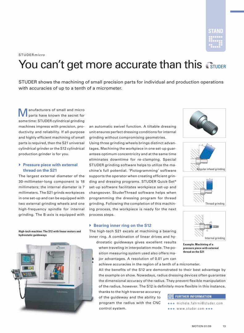
Bearing inner ring on the S12
The high-tech S21 excels at machining a bearing
inner ring. A combination of linear drives and hy-
drostatic guideways gives excellent results
when traveling in interpolation mode. The po-
sition measuring system used also offers ma-
jor advantages. A resolution of 0.01 μm can
achieve accuracies in the region of a tenth of a micrometer.
All the benefi ts of the S12 are demonstrated to their best advantage by
the example on show. Nowadays, radius dressing devices often guarantee
the dimensional accuracy of the radius. They prevent fl exible manipulation
of the radius, however. The S12 is defi nitely more fl exible in this instance,
thanks to the high traverse accuracy
of the guideway and the ability to
program the radius with the CNC
control system.
Manufacturers of small and micro
parts have known the secret for
some time: STUDER cylindrical grinding
machines impress with precision, pro-
ductivity and reliability. If all-purpose
and highly effi cient machining of small
parts is required, then the S21 universal
cylindrical grinder or the S12 cylindrical
production grinder is for you.
Pressure piece with external
thread on the S21
The largest external diameter of the
30-millimeter-long component is 18
millimeters; the internal diameter is 7
millimeters. The S21 grinds workpieces
in one set-up and can be equipped with
two external grinding wheels and one
high-frequency spindle for internal
grinding. The B-axis is equipped with
STUDERmicro
You can’t get more accurate than thisSTUDER shows the machining of small precision parts for individual and production operations with accuracies of up to a tenth of a micrometer.
Example: Machining of a
pressure piece with external
thread on the S21
High-tech machine: The S12 with linear motors and
hydrostatic guideways
Angular infeed grinding
Thread grinding
Internal grinding
+++ m i c h e l e . f a h r n i @ s t u d e r . c o m
+++ w w w . s t u d e r . c o m +++
FURTHER INFORMATION
STAND
L_Station4-5-6_E.indd 13 15.04.2009 12:48:34 Uhr

14 MOTION 01/09
T O O L S & T E C H N O LO GY
STUDER internal
From the inside outSTUDER further expands its portfolio with machines produced by COMBITEC, its new subsidiary. The aim is to increase technical knowhow and application possibilities for internal cylindrical grinding.
grinding collet chucks and machining brittle hard materials. Special features are
the linear spindle arrangement, use of either one or two belt spindles with speeds
of between 28,000 and 60,000 min-1 and cross-slide design. The CT-450 provides
a range of expansion options, such as a C-axis for grinding all types of threads.
CT-960 – a high-end universal machine
The internal, universal and radius grinder CT-960 is a high-precision machine,
with a B-axis swivel to 91 degrees. A turret for up to four spindles permits effi -
cient grinding of small to medium-sized workpieces. In this particular design,
the machine is suited for universal grinding tasks as well as specifi cally for grin-
ding complex workpieces of brittle hard materials like carbide, ceramics or sap-
phire. The optimum stability and rigidity of the CT-960 also permit grinding die
with radii, cones or path contours. The fi nished workpieces have polished surface
quality. An optional CNC-controlled C-axis is available for grinding threads or
Strong partners for every possible
task: With the takeover of Com-
bitec AG of Switzerland, STUDER has
substantially increased its grinding
expertise in the internal cylindrical
grinding sector. Whether die grinding,
series production of precision parts for
the aerospace and hydraulics industry
or diesel injection technology, at Sta-
tion 6, STUDER presents three techni-
cally mature production solutions: the
CT-450L, the CT-960 and the S120.
CT-450L – entry-level
model for new users
The CT-450L CNC internal and universal
cylindrical grinder for new users is the
light version of the COMBITEC bestsell-
er CT-450. With a wide range of applica-
tions, the CT-450L is equally suited to
universal internal grinding applications,
The light version of the CT-450:
The entry-level CT-450L
Innovative injection technology: Just one of many uses in the application area of internal cylindrical grinding
STAND
L_Station4-5-6_E.indd 14 15.04.2009 12:48:36 Uhr

15MOTION 01/09
dent grinding tasks. Optimally suited for an effi cient machining of high-precision
small parts, it is well established in large batch production. Typical applications
are in the area of hydraulic components and increasingly in medical technology,
for example grinding ceramic balls for hip joints. Different handling systems can
be integrated via the well-defi ned loading interface without too much effort. The
automated solution on show perfect-
ly combines productivity with fl exibil-
ity and in addition, it impresses with
short retooling times.
non-circular shapes. Sim-CT software
helps with programming, set-up and
simulation.
S120 – a speedy
production machine
The S120 production internal cylindrical
grinding machine is the ideal compact
internal grinder for one or two indepen-
+ + + m i c h e l e . f a h r n i @ s t u d e r . c o m
+ + + w w w . s t u d e r . c o m + + +
FURTHER INFORMATION
Excellent: The
STUDER S120
combines
productivity and
fl exibility
Internal cylindrical grinding: Efficient machining of
high-precision small parts
L_Station4-5-6_E.indd 15 15.04.2009 12:48:40 Uhr

16 MOTION 01/09
T O O L S & T E C H N O LO GY
SERVICE Qual i t y
Fountain of youth for machinesAnyone who is familiar with possible wear phenomena starts to think about the health of his machine. A professional overhaul extends its service life.
Preventive SCHLEIFRING Service
SCHLEIFRING machines are similar to our bodies in this respect: systematic
servicing carried out by SCHLEIFRING SERVICE (which can be compared to rou-
tine checks by the doctor) extend machine running times and availability and in
addition improve the grinding result. Preventive servicing documents the current
state of the machine. We recommend an annual service with SystemTM. Using
this, SCHLEIFRING SERVICE checks more than 100 points on a checklist and
measures the geometric values and the hysteresis. All the wear parts in the ma-
terial list are replaced as a preventive measure. In addition to this, SERVICE
diagnostics and life cycle monitoring provide valuable insights into the condition
of the grinding machine and recommend that corresponding precautions are
taken. More than 3,000 satisfi ed customers are already enjoying the benefi ts
of SERVICE Check. The specialist knowledge of the SCHLEIFRING experts
means that you can avoid cost-intensive machine down times, particularly in
these economically diffi cult times.
Good and benefi cial
After a complete overhaul by SCHLEIFRING SERVICE the ma-
chines once again operate just as precisely and reliably as
new machines. The modular overhaul system thus works
rather like a fountain of youth. And the process is even more
benefi cial. The cost of a complete overhaul is between 40 and
70 per cent of the price of a new machine.
And by the way: more than 100 overhauls are carried out an-
nually, using nothing but SCHLEIFRING original components.
They are only done in
the relevant produc-
tion factory of the
SCHLEIFRING Group.
High blood pressure is the number
one cause of illness in most indus-
trialized countries. If not detected and
left untreated, it can lead to serious con-
sequences such as heart attacks and
strokes. Yet high blood pressure cannot
be felt; only health checks can supply
the information as to whether it is high-
er than it should be even though every-
thing appears normal. If caught at the
right time, medicines or a preventive
change in lifestyle can help. We often
do not realize how important our health
is until it is too late.
16 MOTMO ION 01/09
terial list are repla
diagnostics and life
of the grinding m
taken. More tha
of SERVICE Che
means that you c
these economica
New from old: An assembly before
and after overhaul
Maintenance cycle: Professional machine diagnostics in three steps
+++ s a n d r o . b o t a z z o @ s e r v i c e a g . n e t
+++ w w w. s e r v i c e a g . n e t +++
FURTHER INFORMATION
Servicing with System TM
More than 100 testing and measuring points
Diagnostics and recommendations
Information on the current state of the grinding machine
Life Cycle Monitoring
The test measurements are evaluated by specialists
STAND
L_Station7-8_E.indd 16 09.04.2009 14:54:38 Uhr

17MOTION 01/09
Two workpieces are
machined simultane-
ously in two different
operations with CBN
wheels using the an-
gular plunging pro-
cess. The cycle time,
including a dressing
component, is less
than 13 seconds. The
workpieces are trans-
ported and sent on
using a paced triple
gripper system.
One of the machine’s special highlights is the dressing system for the CBN
wheels. This uses software that MIKROSA has developed in-house. It uses in-
tegrated sound sensors in two directions to set the dressing start points. This
guarantees a preset dressing depth, not exceeding three μm, on the surface and
the shoulder of the CBN wheel.
A standardized handling system uses the ‘keyhole principle’ to transport the
workpieces into the machine and out again. External handling systems such as
palletizing machines can easily be connected via an interface. Centerless precision
– if all its process technology features are fully utilized, the potential of the KRONOS
S 125 is enormous. The highest quality and productivity, the ability to process a
wide variety of different materials and
the use of versatile grinding techniques
– MIKROSA grinding machines meet
every requirement of the market.
The KRONOS S 125 centerless ex-
ternal cylindrical grinding machine
is designed with a special construction
principle for the use of the CBN grin-
ding technique. It is based on a ther-
mally stable and vibration-damped
moulded mineral machine bed. The
cross-slide systems that are built onto
this bed for the grinding and regulating
wheel side make the centerless grin-
ding machine enormously versatile.
The large number of variations, rang-
ing from throughfeed grinding and
plunge grinding to reciprocating grin-
ding including angular plunging, cycle
changing and offset grinding.
Two operations at once
At the 2009 Grinding Symposium,
MIKROSA is demonstrating the ma-
chine’s versatility, using the machining
of injector needles (Ø 4.0 × 48 mm) in
a high-speed process.
MIKROSA KRONOS S 125
Fit for every challengeIn the high speed grinding of injector needles the MIKROSA KRONOS S 125 demonstrates an unusually fl exible ability to adapt to the grinding task.
The angular plunging process: Simultaneous grinding of injection nozzles
with CBN wheels using different operations on the KRONOS S 125
Vast potential: The KRONOS S 125 was designed from
the start with CBN grinding in mind.
+ + + i r i n a . h a f n e r @ m i k r o s a . c o m
+ + + w w w . m i k r o s a . c o m + + +
FURTHER INFORMATION
DESIGN HIGHLIGHTS
Operation 1
CBN grinding by angular plunging
Pregrinding the shoulder
Pregrinding the tip
Securing with a pressure roller
Operation 2
CBN grinding by angular plunging
Contour grinding
Finishing the face
STAND
L_Station7-8_E.indd 17 09.04.2009 14:54:41 Uhr

Meister Abrasives AG · Switzerland · www.meister-abrasives.com
Make A Quality Decision InternationalMeister Abrasives
L_Station9_E.indd 18 09.04.2009 15:01:31 Uhr

19MOTION 01/09
with wear-free drives enables the tool spindle to be positioned with extreme pre-
cision and at the same time maximizes service life. This ensures the most accurate
grinding results, even in the case of camshafts. The CamGrind S version of this
machine is already used successfully for camshaft grinding.
The SCHAUDT ShaftGrind S is de-
signed to machine a variety of shafts
effi ciently. It has WOP-S programming,
which is based on the Siemens 840D
control panel and helps to generate sur-
face contours such as polygons, ellipses
and free profi les with ease. The machine
is also eminently suitable for high-speed
peel grinding (HSP) processes and slot
grinding with CBN.
Machining transmission shafts
Seats for transmission shafts are usu-
ally ground in an indexing process, ei-
ther by straight plunging or high-speed
peel grinding. The ShaftGrind S with its
S2 tilting spindle enables different
widths of grinding wheel to be used and
permits the interpolation of undercutting
and plunge cutting with an electroplated
grinding wheel. This markedly increases
the productivity of the machine. When
high speed plunge grinding with CBN,
the ShaftGrind S reaches cutting speeds
of 200 m/s. This, together with the car-
bon-carrier system of the machine,
makes the process even more produc-
tive. The ShaftGrind S is designed for
lubrication with emulsion or oil in com-
bination with CBN grinding wheels.
Grinding wheels that are 480 millimeters
in diameter guarantee long tool life. An
optional hydrostatic guide for the X axis
SCHAUDT Shaf tGr ind S
The perfect shaftTransmission shafts up to 650 millimeters long are the province of the SCHAUDT ShaftGrind S with tilting spindle technology
Effi cient machining
taken care of:
Machine confi gura-
tion of the ShaftGrind
S with tilting spindle
that can be swung in
+ + + i r i n a . h a f n e r @ s c h a u d t . c o m
+ + + w w w . s c h a u d t . c o m + + +
FURTHER INFORMATION
Outstanding results: The ShaftGrind S
has cutting speeds of 200 m/s
STAND
ADVANTAGES AND PERFORMANCE
Machining of round and non-round materials up to 650 mm long,
weighing up to 50 kg
Programming with WOP-S is quick and easy
Hydrostatic guide for the X axis (optional extra)
Moulded mineral machine bed (Granitan® S 103) with optimized damping
properties and extremely high thermal stability
Technical specifi cations
Sinumerik 840D controller
Integral SPEED-LOAD loader (option)
Grinding length/tip height: 650 mm / 175 mm
Spindle confi guration
Grinding wheel diameters large/small wheel: 480 mm / 140 mm
Grinding wheel widths large/small wheel: 80 mm / 70 mm
Output using large/small wheel: 40 kW/8 kW
2 grinding spindle locations (one spindle can be tilted)
L_Station9_E.indd 19 09.04.2009 15:01:32 Uhr
20 MOTION 01/09
T O O L S & T E C H N O LO GY
SCHAUDT CamGrind L2
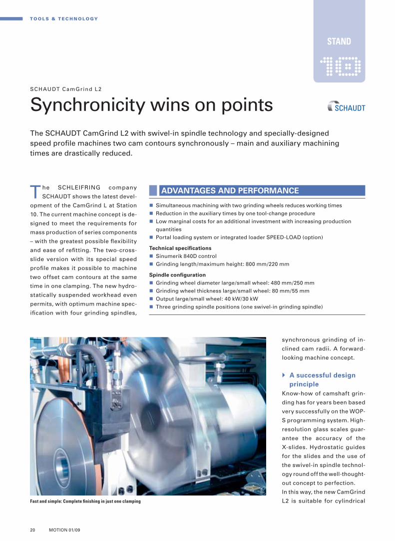
Synchronicity wins on pointsThe SCHAUDT CamGrind L2 with swivel-in spindle technology and specially-designed speed profi le machines two cam contours synchronously – main and auxiliary machining times are drastically reduced.
The SCHLEIFRING company
SCHAUDT shows the latest devel-
opment of the CamGrind L at Station
10. The current machine concept is de-
signed to meet the requirements for
mass production of series components
– with the greatest possible fl exibility
and ease of refi tting. The two-cross-
slide version with its special speed
profi le makes it possible to machine
two offset cam contours at the same
time in one clamping. The new hydro-
statically suspended workhead even
permits, with optimum machine spec-
ifi cation with four grinding spindles,
Fast and simple: Complete fi nishing in just one clamping
ADVANTAGES AND PERFORMANCE
Simultaneous machining with two grinding wheels reduces working times
Reduction in the auxiliary times by one tool-change procedure
Low marginal costs for an additional investment with increasing production
quantities
Portal loading system or integrated loader SPEED-LOAD (option)
Technical specifi cations
Sinumerik 840D control
Grinding length/maximum height: 800 mm/220 mm
Spindle confi guration
Grinding wheel diameter large/small wheel: 480 mm/250 mm
Grinding wheel thickness large/small wheel: 80 mm/55 mm
Output large/small wheel: 40 kW/30 kW
Three grinding spindle positions (one swivel-in grinding spindle)
synchronous grinding of in-
clined cam radii. A forward-
looking machine concept.
A successful design
principle
Know-how of camshaft grin-
ding has for years been based
very successfully on the WOP-
S programming system. High-
resolution glass scales guar-
antee the accuracy of the
X-slides. Hydrostatic guides
for the slides and the use of
the swivel-in spindle technol-
ogy round off the well-thought-
out concept to perfection.
In this way, the new CamGrind
L2 is suitable for cylindrical
STAND
L_Station10_E.indd 20 09.04.2009 15:04:18 Uhr

21MOTION 01/09
When clamping becomes critical …Extraordinary applications demand extraordinary solutions. Many workpieces cannot be properly clamped by virtue of their unique characteristics. We develop targeted customized chucking systems.
FORKARDT SCHWEIZ GMBHIndustriestrasse 3, CH-8307 EffretikonTel. +41 52 355 31 31, [email protected] ITW Workholding Comp
WWW.FORKARDT.CH Highest quality and precision within the μm range
and non-circular grinding as well as for
keyway plunge grinding and HSP-grin-
ding with CBN. On this type of machine,
only CBN tools with ceramic, galvanic
or metallic bonding are used.
Finished: A camshaft after the grinding process
+ + + i r i n a . h a f n e r @ s c h a u d t . c o m
+ + + w w w . s c h a u d t . c o m + + +
FURTHER INFORMATION
[2][2][1][1]
Deep insight: [1] Example
of a machine confi gura-
tion with a swivel-in
grinding spindle [2] View
of the inside of the
CamGrind L2 with the
two-slide version
L_Station10_E.indd 21 09.04.2009 15:04:24 Uhr

22 MOTION 01/09
T O O L S & T E C H N O LO GY
STUDER f lexible
Seven at one strokeWith the upgrade to three cross-slides, the unique combined machining system STUDER S242 has become the most fl exible hard fi ne machining center available.
confi guration possibilities for external and internal grinding
(with up to three internal grinding spindles). External or internal
hard turning, hard reaming, milling (with up to twelve driven
tool positions) and drilling all benefi t from the wide range of
confi gurations. Equipped with two cross-slides, the S242 has a
center distance of 400 and 1000 millimeters. With the three cross-
slide version, an additional variant with a center distance of 800
millimeters is available. Unrestricted chip removal when hard
turning is ensured by the inclined GRANITAN® machine bed. A
chip conveyor takes care of swarf discharge.
Quick retooling
The S242 is mainly used in the sectors of machine tools and tool
making, pneumatics/hydraulics and the electrical/electronic
sector. High fl exibility of the machine and fast retooling with a
synchronous opposed spindle on the tailstock (W-axis) makes the S242 an in-
teresting proposition, also for contract manufacturers who machine mainly in-
dividual components (part families) and small lot sizes. Newly developed control
measuring cycles with a measuring probe mounted in the revolving turret allows
the automatic calculation of insert wear. This process allows measuring data to
be recorded and printed. The well-proven in-house design STUDER easyLoad
XL is offered for workpiece automation. Combining the machining processes of
cylindrical grinding and hard turning with parallel grinding spindles and a turret
guarantees productive, accurate and reliable complete machining of workpieces.
STUDER demonstrates these processes
visually during the Grinding Symposium
with machining shafts and chuck compo-
nents at Station 11.
Arange of capabilities that is second
to none: ongoing continued devel-
opment has meant that nowadays the
STUDER S242 is capable of at least
seven machining processes: external
hard turning and grinding, milling of
small grooves, internal hard turning and
grinding, external thread turning, drill-
ing and hard reaming. This means that
the S242 is capable of machining spin-
dles and guide pillars, pump pinions,
armature shafts, tool holders and other
specifi c components, among others.
Complete machining of a variety of
workpieces in a single clamping makes
increases in productivity of up to 70 per
cent a real possibility.
Wide range of confi gurations
The S242 has parallel grinding spindles,
a turret as well as two or three cross-
slides. This results in ten or rather 15
Flexible and multi-functional: S242 with three cross-slides (external
grinding, turret, internal grinding turret)
+++ m i c h e l e . f a h r n i @ s t u d e r . c o m
+++ w w w . s t u d e r . c o m + ++
FURTHER INFORMATION
FLEXIBLE, PRODUCTIVE, ACCURATE, RELIABLE
Less production time and down time due to quick retooling of the machine
High positional and rotational accuracy
Complete machining in a single clamping
Appropriate surface structures
In-process measuring of diameter and length
STAND
L_Station11-12_E.indd 22 15.04.2009 12:50:11 Uhr

23MOTION 01/09
STUDER inte l l igent
Intelligent software pays offStuderTechnology optimizes the grinding process – and increases the effi ciency of universal cylindrical grinding machines by 50 per cent or more.
automatically calculates the process parameters. At the push of a button, the
operator learns which in-feed speeds, changeover points, dressing amounts and
spark-out time the system recommends.
Profi ting from the knowledge of many
Behind all these intelligent functions is a technology database with invaluable
expert knowledge. It makes sure that the machine control is always able to choose
the best available data. Unlike most operators who often habitually work with
the same standard values and who rarely manage to keep to the tolerances on
their fi rst attempt. Such a process is ineffi cient and requires time-consuming
optimization procedures. However, if StuderTechnology is used, near-optimum
values are reached straight away, resulting in reduced set-up times and grinding
times lowered by up to 25 per cent. In addition, the optimization time is often
zero and costly errors hardly ever happen. StuderTechnology with its many and
various functions like virtual machine set-up
and program simulation result in an early
detection of errors and is additionally ex-
tremely user-friendly.
+++ m i c h e l e . f a h r n i @ s t u d e r . c o m
+++ w w w . s t u d e r . c o m +++
FURTHER INFORMATION
Intelligent software makes it possible:
machine operators can once again
concentrate on their key task – the quick,
safe and simple generation of a grinding
program. At Station 12, STUDER dem-
onstrates with the S31 and S33 univer-
sal cylindrical grinding machines how
StuderGRIND software and the Studer-
Technology module can contribute to
reducing cycle times by 50 per cent.
Everything at the
push of a button
Some of the tasks of a machine opera-
tor are to choose the appropriate tool-
ing, set up and retool the machine
quickly, develop the grinding process
and grind accurate parts. He should
be able to leave everything else to
the StuderGRIND CAM software and
StuderTechnology. He only has to enter
the type of material, specifi cation of the
grinding wheel, type of dressing tool
and certain other factors. The software
Graphic visualization: User-friendly work with
StuderTechnology
STAND
Achieving the best with StuderTechnology
StuderTechnology versus empirical values (after optimization): The software is most benefi cial for small and medium
quantities. Example: a shaft is to be machined on three diameters. The surface accuracy should be Ra 0.3, the
roundness no more than 1 μm. A total of six values are measured. When grinding with empirical values the tolerances
were not achieved and time-consuming optimization was necessary
StuderTech
StuderTech
StuderTech
Tim
e [h
:min
:s]
8 : 24 : 00
7 : 12 : 00
6 : 00 : 00
4 : 48 : 00
3 : 36 : 00
2 : 24 : 00
1 : 12 : 00
0 : 00 : 00
Empirical values
Empirical values
Empirical values
DocumentationOptimization timeDressing timeGrinding timeProgramming
– 90 % – 75 %
1 unit 10 unit 100 unit
– 25 %
L_Station11-12_E.indd 23 15.04.2009 12:50:13 Uhr

24 MOTION 01/09
T O O L S & T E C H N O LO GY
EWAG COMPACT L INE
Compact? Great! The EWAG COMPACT LINE scores with its compact design, ergonomic operation and its integrated robot system for fl exible manufacture of inserts.
clamping systems are mechanically identically installed on the B-axis and are
identified by a ‘plug and play’ system. The result is maximum flexibility and
shortest changeover times.
Dressing, regenerating, crushing
The ‘three-in-one’ sharpening unit: dressing – regenerating – crushing provides
perfect grinding wheel concentricity and high repeat accuracy of processes. 3D
measuring of workpieces in one clamping ensures the required tolerances are
met starting with the fi rst part. Loading is carried out with the integrated 6-axis
FANUC robot which increases the level of machine automation and permits
autonomous multi-shift operation. The
COMPACT LINE which incorpo-
rates 5-axis CNC kinematics,
direct drive of the grinding
spindle and linear technology
allows users to effortlessly
keep pace with changing mar-
ket requirements.
The EWAG COMPACT LINE is de-
signed for the fl exible and highly
precise manufacturing or resharpening
of indexable inserts in all materials.
Whether the material is carbide, cer-
met, ceramic or super-hard CBN/PCD
– the CNC grinding machine meets all
of the requirements for precision and
speed – especially with the realization
of complex workpiece geometries. The
machine is fi tted with the new CBN/
PCD module for grinding super-hard
materials and now also for machining
diamond cutting materials, as EWAG
demonstrates at Station 13.
The COMPACT LINE sets new standards
in small spaces with compact construc-
tion, ergonomic operation and an inte-
grated robot system. Inside the ma-
chine, everything is positioned close to
the working B-axis; the travel ranges
for axes and robots are thus kept to a
minimum, cycle and down times are
shortened considerably and productiv-
ity is increased. The entire machine
interior as well as all control elements
are accessible from one position.
Fast, accurate, autonomous
A rapid change system allows the op-
erator to exchange the grinding wheels
effortlessly at the push of a button.
The HSKE 50 clamping system for
grinding wheels ensures quick and ac-
curate changeover of grinding wheel
sets. The workpieces are fixed to the
clamping device with a tension pin. All
+++ t h o m a s . f i s c h e r @ e w a g . c o m
+++ w w w . e w a g . c o m +++
FURTHER INFORMATION
EWAG COMPACT LINE:
Grinding in the smallest space
Ergonomic: Control elements and machine
interior are accessible from one position
New measures: All grinding programs can be
programmed on the touch screen panel
STAND
L_Station13-14_E.indd 24 09.04.2009 15:22:10 Uhr
25MOTION 01/09
PCD. EWAG guarantees highest concentricity requirements and geometric tol-
erances by using a special chuck which allows automatic tool changing. Fully
automatic loading of the machine is carried out by a 6-axis robot. Each EWAMATIC
LINE meets specifi c customer requirements. Superior fl exibility makes a mul-
titude of grinding operations possible in one clamping, guaranteed by the star-
shaped grinding head with its repeat accuracy of 2 μm. It can hold up to twelve
grinding wheels. Once the grinding wheel has been dressed on the machine,
concentricity and run-out are guaranteed at the highest level. Features such as
pressure-controlled grinding, automatic grinding wheel regeneration and inte-
grated measuring cycles with adequate compensation make fully automatic
grinding of CBN and PCD tools possible. The machine can be equipped with an
eroding process for the production of PCD tools. Users achieve close shape and
positional tolerances with effi cient eroding and grinding in one clamping. Three
criteria are the core of the machine autonomy:
Automatic feed control
Integrated dressing of the grinding wheels
Dimensional measuring directly on the machine
Functionality
The EWAMATIC LINE has another big advantage: the user can employ grinding
wheels of up to 300 millimeters diameter and also the smallest mounted points.
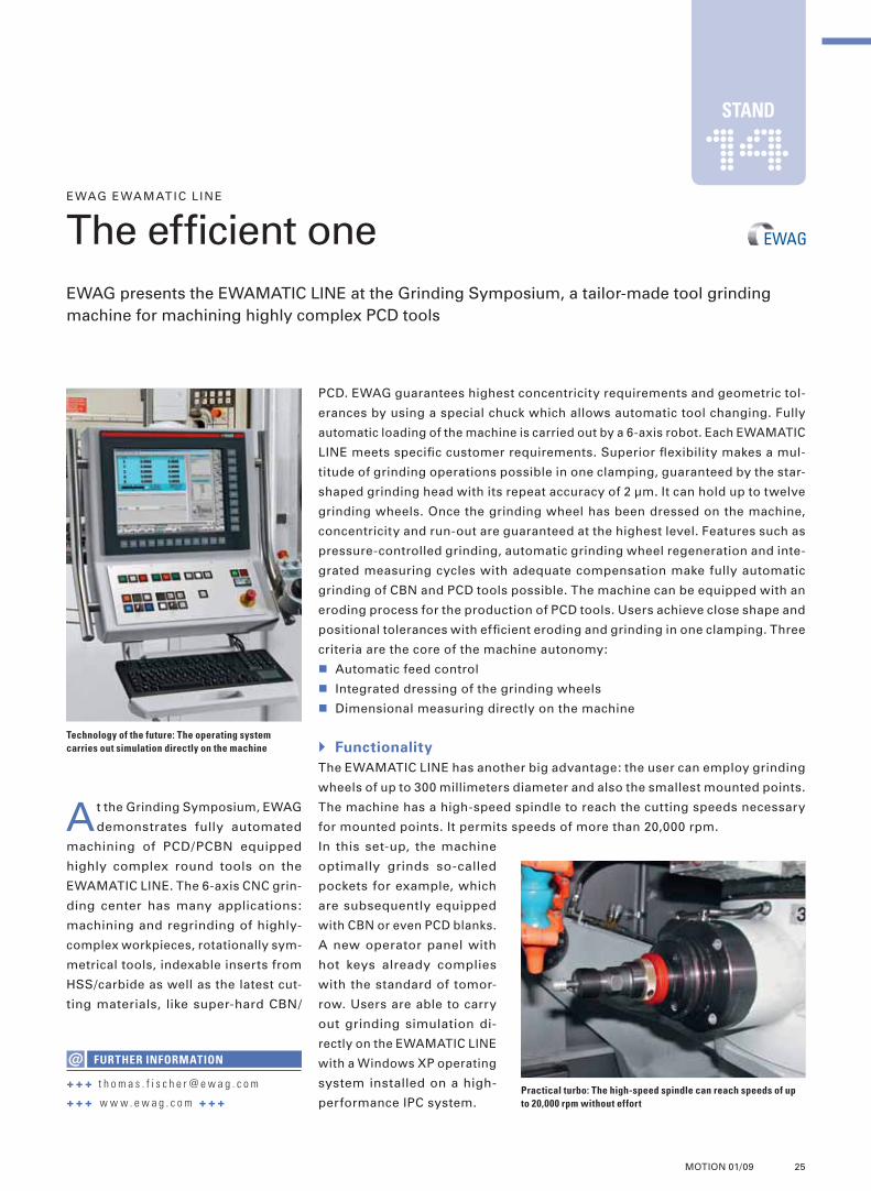
The machine has a high-speed spindle to reach the cutting speeds necessary
for mounted points. It permits speeds of more than 20,000 rpm.
In this set-up, the machine
optimally grinds so-called
pockets for example, which
are subsequently equipped
with CBN or even PCD blanks.
A new operator panel with
hot keys already complies
with the standard of tomor-
row. Users are able to carry
out grinding simulation di-
rectly on the EWAMATIC LINE
with a Windows XP operating
system installed on a high-
performance IPC system.
At the Grinding Symposium, EWAG
demonstrates fully automated
machining of PCD/PCBN equipped
highly complex round tools on the
EWAMATIC LINE. The 6-axis CNC grin-
ding center has many applications:
machining and regrinding of highly-
complex workpieces, rotationally sym-
metrical tools, indexable inserts from
HSS/carbide as well as the latest cut-
ting materials, like super-hard CBN/
EWAG EWAMATIC L INE
The effi cient oneEWAG presents the EWAMATIC LINE at the Grinding Symposium, a tailor-made tool grinding machine for machining highly complex PCD tools
+ + + t h o m a s . f i s c h e r @ e w a g . c o m
+ + + w w w . e w a g . c o m + + +
FURTHER INFORMATION
Technology of the future: The operating system
carries out simulation directly on the machine
Practical turbo: The high-speed spindle can reach speeds of up
to 20,000 rpm without effort
STAND
L_Station13-14_E.indd 25 17.04.2009 11:29:45 Uhr

26 MOTION 01/09
T O O L S & T E C H N O LO GY
Micro tools
High-performance double actThe HELITRONIC MICRO and the HELICHECK PLUS are the perfect machine combination from WALTER for the manufacture and measurement of micro tools of the highest surface quality.
trolled via integral high-resolution measuring systems which
produce precise movements with simultaneously high dy-
namics. The grinding spindle head is equipped with three
grinding spindles guaranteeing a high degree of fl exibility.
A secondary X-axis allows for the precise and automatic
positioning of tools to the center of rotation of the C-axis.
Additional guiding and support of the workpieces by hy-
draulically activated steady rests supports with fi ne adjust-
ment ensure high dimensional and rotational accuracies.
The machine concept is complemented by an integrated
loading system served by a 6-axis industrial robot for work-
piece loading.
HELICHECK PLUS
Optical, non-contact measuring technologies play a decisive
role, especially with delicate materials and micro dimen-
sions. WALTER sets new standards with the HELICHECK
PLUS. The fourth camera with 400× magnifi cation provides
the deciding PLUS element and increases the application
range for tools as small as 0.1 millimeter diameter. Front
and top light cameras also magnify the object to be mea-
sured by 400 times. Even the smallest details become vis-
ible and measurable. Primarily, it comes down to perfect
lighting of the micro tools which are barely visible with
the naked eye. WALTER sharpens your vision by effi -
cient image processing and easy-to-use measuring
control. A special edge detection system, optimized
lighting and image enhancement techniques ensure
that even high-gloss polished, coated or matt surfaces
can be measured with high repeatability.
The development of micro tools has
seen a rapid upswing in recent
years. They are used for machining the
smallest components in the electronics
industry and the medical and dental
sector and they require the utmost pre-
cision. Without accurate measuring
technology the manufacture of preci-
sion micro tools is no longer possible.
At Station 15, WALTER shows how the
surface quality of micro tools has a
considerable infl uence on the service
life of the machine as well as on the
quality of the workpiece.
HELITRONIC MICRO
The HELITRONIC MICRO provides all
the prerequisites for highly accurate
grinding results for tools within the 0.5
to 10 millimeter diameter range. The
machine has six CNC grinding axes
with linear motors and torque motors
on all rotational axes. All axes are con-
[1][1]
[2][2]
[3][3]
[4][4]
[5][5]
Well measured:
First-class surface
quality with the
HELITRONIC MICRO [1].
The HELICHECK PLUS
magnifies object 50 to
400 times [2 + 3]
Result of the image
enhancement technique
with a micro tool
Ø 0.8 mm [4 + 5]
Ideal conditions: The HELITRONIC MICRO achieves
high-precision grinding results
+++ c h r i s t o p h . e h r l e r @ w a l t e r - m a c h i n e s . d e
+++ w w w.w a l t e r - m a c h i n e s . d e +++
FURTHER INFORMATION
STAND
0.2 mm diameter magnifi ed 400 times
0.2 mm diameter magnifi ed 50 times
L_Station15-16-17_E.indd 26 15.04.2009 14:02:38 Uhr

27MOTION 01/09
Changer with 8 positions
The trend is towards an increasing range of geometries
and longer unmanned machining cycles. WALTER takes
on this development with the electrode/grinding
wheel changer with 8 positions for the HELITRONIC
POWER DIAMOND which holds up to 24 electrodes
or grinding wheels respectively. This ensures ex-
cellent machining properties of PCD and carbide
tools with extremely complex tool geometries.
When eroding stepped contour tools with different
concave contour radii for example, the best-suited rotat-
ing electrode is simply selected.
The coolant supply manifold is connected to the electrode/grin-
ding wheel adaptors. This guarantees optimum cooling at all times during the
production process when tool grinding and optimum protection when eroding.
In addition, the tool changer extends unmanned machining time for night-shift
and week-end operation. The two-in-one concept of the HELITRONIC POWER
DIAMOND enables fl exible reaction to current production requirements. Auto-
matic changeover from eroding to grinding, from machining PCD tools to process-
ing or resharpening carbide tools
is possible. Furthermore, complete
machining of almost all types of
tools is also feasible.
WALTER’s answer to the
ever-increasing stan-
dard of surface accuracy and
cutting edge quality is the
HELITRONIC POWER
DIAMOND. The machine
impresses with a 4-stage
erosion process which
accurately produces
perfect cutting edges
and extraordinary sur-
face qualities of up to Ra =
0.1 μm when machining PCD
tools. It is quite impressive:
The HELITRONIC POWER
DIAMOND achieves only minimum
stock removal rates due to a fi ne ad-
justment of power during the erosion
process. The result is PCD cutting
edges with perfect surface quality and
greatly improved chip resistance.
Workpieces manufactured in this way
now almost achieve the quality of
ground PCD tools.
WALTER HELITRONIC POWER DIAMOND
Only the cutting edge countsThe two-in-one concept of the WALTER HELITRONIC POWER DIAMOND offers a risk-free entry into the PCD business.
+++ c h r i s t o p h . e h r l e r @ w a l t e r - m a c h i n e s . d e
+++ w w w . w a l t e r - m a c h i n e s . d e +++
FURTHER INFORMATION
[1][1]
Immaculate: [1] The improved cutting edge quality is clearly visible [2] Edge rounding of
3.9 μm at the PCD tool cutting edge
Head-turner: The changer is loaded with up to 24
grinding wheels
Superior
quality: PCD step
drill and carbide
full-radius milling
cutter with perfect
surface quality
[2][2]
STAND
L_Station15-16-17_E.indd 27 15.04.2009 14:02:43 Uhr
28 MOTION 01/09
T O O L S & T E C H N O LO GY
WALTER HELITRONIC ToolStudio
The easy way to produce a toolThe new version of the HELITRONIC ToolStudio grinding software from WALTER is even more effi cient and simplifi es grinding of complex tool geometries.
ter how small, the tool can be individually tailored. Further key functions:
‘Click & Edit’: Simply click on the 3D simulation to see the relevant
geometries and technology parameters
Time saving: Path-optimized calculation of positioning movements
between operations and cutting edges
Safety: Automatic collision check prior to manufacture
Tool design made easy
The modular design of the new version of HELITRONIC ToolStudio permits
variable and individual configuration of all important parameters. Using the
modular principle, any number of operations can be added or copied – a huge
advantage when designing tools. All this extra flexibility comes in handy when
processing step tools (for example step drills or stepped milling cutters).
WALTER has improved the tool wizard for step tools so that it can now be re-
started at any time even after manually adding or copying individual operations.
The amount of work required by the operator has been considerably reduced;
with just a few clicks he can replace an existing drill cutting edge on a special-
ized step drill.
Only a few years ago, tools with
variable helix angles, uneven in-
dexing between the individual cutting
edges and constant flute width across
the body were categorized as special
tools. Nowadays, complex geometries
such as these are becoming part of the
bread-and-butter work of many tool
manufacturers and resharpening com-
panies. HELITRONIC ToolStudio is the
efficient software package for the
HELITRONIC tool grinding machine
series from WALTER. It covers every
aspect of the configuration of tool ge-
ometries.
Minimal effort
Using the integrated wizard technol-
ogy, tools can be modeled in a simple
way. The required data input is reduced
to a minimum. The system only re-
quests the most important tool param-
eters and automatically runs through
the necessary input screens. At the
same time the HELITRONIC ToolStudio
software accesses WALTER’s knowl-
edge database which stores important
tool grinding experience and helps to
fi nd a speedy solution for all produc-
tion tasks. The software complements
the entries with relevant geometry and
technology parameters such as grin-
ding wheel sets and grinding feed
rates, for example. Based on the basic
tool model created and high-precision
3D simulation which is updated for
each and every modifi cation – no mat-
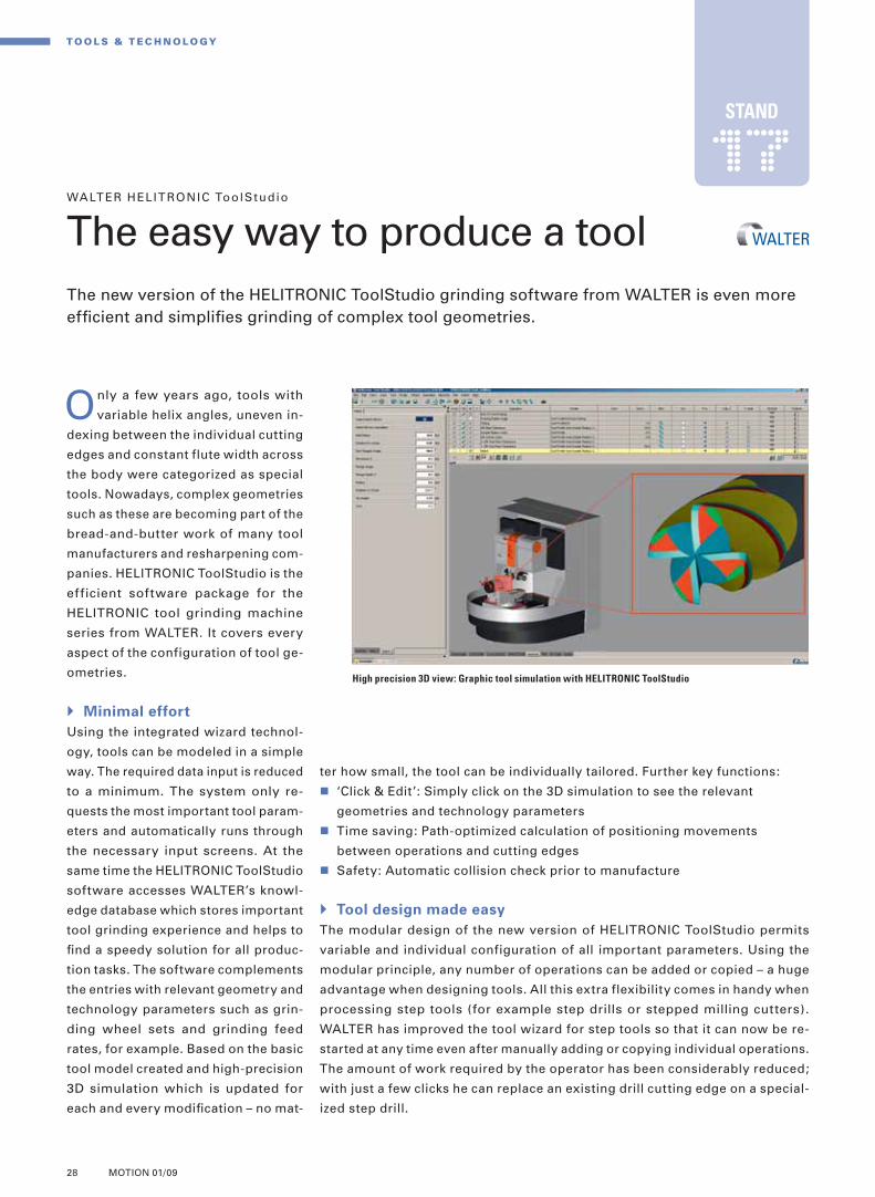
High precision 3D view: Graphic tool simulation with HELITRONIC ToolStudio
STAND
L_Station15-16-17_E.indd 28 15.04.2009 14:02:45 Uhr

29MOTION 01/09
tribution of measuring points can be freely confi gured. While the tool param-
eters are being defi ned, the HELITRONIC ToolStudio software calculates the
fl ute shape with specifi c focus on all the determining factors. The path of the
helical angle, the radius of the grinding wheel bond or the angle of the grinding
wheel are just some examples. Time-consuming checking of the fl ute shape is
not required. Accurately parallel clearance angles and land widths on the step
are produced without the need for long-winded manual corrections. The capa-
bility of the HELITRONIC ToolStudio
software is unrivaled in the market
for grinding software. Visitors to
Stand 17 can see for themselves.
Useful touch functions
In the production of step tools on
WALTER machines two particular prob-
ing functions of the software are very
helpful. One serves in the alignment of
coolant holes and measures the con-
centricity of the blank. The other scans
the fl ute path along the contour of the
tool. It is possible to check individual
diameters or steps as well as entire
profi le contours in this way. The dis-
Replaced with a few clicks: Drill cutting edge using the example of a special tool
with variable helix design and two steps
Virtual probing: HELITRONIC ToolStudio records individual diameters and steps as
well as the entire profi le contour
+++ c h r i s t o p h .e h r l e r @ w a l t e r- m a c h i n e s .d e
+++ w w w.w a l t e r- m a c h i n e s .d e +++
FURTHER INFORMATION
L_Station15-16-17_E.indd 29 15.04.2009 14:02:47 Uhr

The global economy in recession – expertise and technological leadership secure exports of high-quality capital equipment even in times of crisis.
Sucked into the recession: Key industries like the
automotive sector have been affected
of the recession. The automotive industry, machine construction and the electron-ics industry are particularly severely affected.
From product manufacturer to systems provider
However, there is one piece of good news amidst all the doom and gloom: the global economic crisis fi nds German and Swiss industry in a comparatively sta-ble condition. In recent years, many fi rms in both countries have undergone a unique transformation from product manufacturer to systems provider. Instead of just selling machines, electronic devices or vehicles, they are now selling end-to-end, innovative solutions with an industrial core packaged in a wide range of upstream and downstream services – from planning and organization to manage-ment, operation, fi nancing, insurance, maintenance and modernization. German and Swiss companies have become global market leaders in many industries, offering very attractive high-quality, all-round packages of products and ser-
T here is no doubt that the global economy is in a crisis. What is un-
certain is how long the recession will last and how deeply it will affect indi-vidual economies. The bad economic tidings of recent months do not provide much hope because, for the fi rst time in decades, the slowdown is affecting the whole world at the same time. Even emerging economies and exporters of raw material are facing diffi cult times. The crisis on the fi nancial market has become a global economic crisis. Where-as at the beginning it affected only a few isolated sectors like the lending busi-ness, now there are hardly any areas that are not being sucked into the whirlpool
Lec ture I -1 | May 6 , 20 09 | 14 .0 0
Production in the global economic climate
M A R K E T S & T R E N DS
30 MOTION 01/09
By Prof. Thomas Straubhaar
L_Vortrag_I1_Straubhaar_E.indd 30 09.04.2009 15:32:13 Uhr

vices. It is not so much low costs and prices that give them their competitive advantage. Instead, it is their effective organization and effi cient management of complex international value creation networks that give them a monopoly position that goes beyond cost leader-ship. Technological leadership enables them to set the rules and to charge high prices with generous margins. It makes local fi rms less susceptible to short-term economic problems. This means that many German and Swiss fi rms are not attempting to offer cheaper prod-ucts and services than the internation-al competition. Their aim is to be tech-nological leaders, both now and in the future. Technological leaders are not as involved in the cut-throat international price competition and are not as exclu-sively cost-dependent. They set their own prices. This means that they re-main internationally competitive and can sell their products and services even in times of moderate to serious economic diffi culty.
The future of the
global economy
The global recession will pass, hope-fully sooner rather than later. Neverthe-less, it is the cause of increasing uncer-tainty: Will the global economy be the same after the recession? Does theglobal economic crisis spell the end of globalization? Globalization has swept across the world like a hurricane in the last twenty years. Protective fences and
[2][2]
iron curtains have been pulled down and national borders swept away. Interna-tional division of labor and specialization have acquired a new, global dimension. The links in the value chain have been broken down into smaller and smaller units and distributed all over the world. ‘As long as it’s cheap’ became the guiding principle. It seemed as if everything was possible. The Earth was reduced to a fl at disk. Long distances and the associated costs apparently no longer played a part in the new economic geography. Is the crisis on the fi nancial market and the global recession leading to a re-versal of this trend? Has the international division of labor passed its peak? Are high export growth rates a thing of the past? And will we now return increas-ingly to local rather than global production? It almost looks like it. International sales have collapsed. Emerging economies are facing a lack of demand for their consumer goods and raw materials and therefore do not have the money to go shopping on the world markets. The absence of power in the American growth engine is putting the brakes on economic growth worldwide. This is particularly true of Southeast Asia and Latin America, regions in which production is heavily dependent on the U.S. market.Despite all the economic trouble spots, there are enough grounds for optimism for German and Swiss industry. This view is supported by the German and Swiss fi rms’ high level of expertise and technological leadership. Small and medium-sized companies in these countries continue to be favorably positioned with a tendency towards process-oriented rather than product-oriented innovations. Expertise and technological leadership secure exports of high-quality capital equipment, par-ticularly in times of economic diffi culty. Demand for infrastructure investment, capital equipment, ma-chinery, devices and ap-pliances in the emerging economies of Southeast Asia, the oil-exporting nations of the Arab world and the new EU coun-tries of Central and Eas-tern Europe will continue – despite, during and aft-er the fi nancial crisis. German and Swiss fi rms will soon start to benefi t from it again.
31MOTION 01/09
ABOUT THE SPEAKER
Prof. Thomas Straubhaar has been Director of the Hamburg Institute of International Economics (HWWI) since 2005. His key research areas include international economic relations, economic framework policy, economics of education and population economics
THE WHOLE WORLD IS AFFECTED SOLUTIONS TO THE CRISIS
What does the future hold? [1] For the fi rst time in decades the slowdown is affecting the whole world simultaneously [2] There are many factors infl uencing the
economic equilibrium. Expertise and technological leadership secure exports of high-quality capital equipment, particularly in times of economic diffi culty
10810610410210098969492
98 99 00 01 02 03 04 05 06 07 08 09
Slowdown in the OECD countries
1101081061041021009896949290
98 99 00 01 02 03 04 05 06 07 08 09
Slowdown in the USA
115
110
105
100
95
90
8598 99 00 01 02 03 04 05 06 07 08 09
Slowdown in China
The psychology of expectations
10810610410210098969492
98 99 00 01 02 03 04 05 06 07 08 09
Slowdown in the euro zone
[1][1]
EmploymentPrice level
Monetary policy
Fiscal policy Labor market policy
Foreign trade policy
Stability goals
Sou
rce:
OE
CD
L_Vortrag_I1_Straubhaar_E.indd 31 09.04.2009 15:32:15 Uhr

32 MOTION 01/09
M A R K E T S & T R E N DS
resources assigned to specifi c operations largely determine the fl exibility and
suitability for innovation of manufacturing processes. The greater this commit-
ment, the higher the quantitative performance and process reliability that can be
achieved. However, there is also the risk that the required values cannot be reached
by changing the components or processing conditions. Therefore sustainable
process design must also integrate new technology into existing process chains
quickly and reliably.
Potential for development
Process improvements depend on three factors, innovative machine technology,
new developments in grinding and dressing tools and improved process condi-
tions. The effi cient introduction of new techniques requires an in-depth knowl-
edge of the effective relationships in the grinding process. Only when the inter-
Conventional processes in grinding
technology are under constant pres-
sure to improve still further in answer to
the increasing performance of alterna-
tive cutting techniques. What we see is
that on the one hand, processes with
geometrically determined cutting are
competitive in the fi elds of cylindrical,
surface and profi le machining because
they have great fl exibility, high metal
removal rates and low consumption of
resources. On the other hand, the poten-
tial offered by metal removing pro-
cesses is their high process reliability
when machining complex contours to
the highest quality specifi cations.
Sustainable production
The delicate balance between output
and precision provides an opportunity
for grinding technology. Against a back-
ground of runaway proliferation of tech-
nological innovations, there are com-
petitive advantages that do not depend
on performance and precision alone.
Future manufacturing strategies will
only be successful in the long term if
they save valuable resources and can
react fl exibly to changing technical and
economic constraints. Only innovative
companies that are the fastest to imple-
ment new results from research and
development will be competitive in the
world markets of the future. The capital
Grinding processes are a delicate balance of high precision and high output.
Opportunities for grinding
technology: Technologi-
cal innovations secure
competitive advantages
Lec ture I -2 | May 6 , 20 09 | 14 .45
Precision machining, quo vadis?
By Prof. Eckart Uhlmann
L_Vortrag_I2_Uhlmann_E.indd 32 15.04.2009 14:04:02 Uhr

33MOTION 01/09
wheels without slots and do not increase the thermal stresses on the workpiece.
The slotting causes modulation of the machining forces and thus dynamic
excitation of the grinding process. This excitation only leads to process instability
if the speed ratio of the grinding wheel to the workpiece, multiplied by the number
of grooves, comes to a whole number. For all other speed ratios, although the
grooving causes greater oscillation amplitudes than are obtained with ungrooved
grinding tools, they have no signifi cant effect on roughness and roundness when
used in machines that have high dynamic rigidity.
In rapid stroke profi le grinding of materials that are diffi cult to machine, such as
high-performance ceramic and nickel-based alloys, there are currently two chal-
lenges to be faced. These are the analysis and implementation of the interaction
between kinematic parameters, coolant conditions and the grinding wheel spec-
ifi cation. Because the grinding energies are lower it is possible to perform rap-
id stroke grinding with a reduced coolant requirement at high metal removal
rates and with a low level of damage. However, it is only possible to achieve
suffi ciently true profi les if the combination of the thermal and mechanical stres-
ses in the critical zone leads to microcrystalline splitting of the abrasive grit.
Grinding wheel design therefore depends on full knowledge of the mechanical
fracturing and tribological properties of innovative abrasive grits.
Here, too, system-
atic analysis of the
potential applica-
tions of innovative
products makes a
signifi cant contri-
bution in combina-
tion with techno-
logical studies and
ever more powerful
modeling tech-
niques.
actions between the machine, the tool
and the process are known can the en-
gineer combine the solutions offered
by the wealth of innovations on the
market with maximum development
potential. He is supported by innovative
process models from research and de-
velopment. An example is the explicit
modeling of process conditions and
their effects on the grinding process.
What is the effect on process parameters
and the work result in external cylindri-
cal plunge grinding if slots are made in
the grinding wheels at certain locations?
A research project that is currently un-
derway at the Institute for Machine Tools
and Factory Management (IWF) at Berlin
University of Technology is investigating
this very question. The purpose of the
research is to be able to specify the ef-
fective relationships explicitly. To do this,
the interaction between the tool and the
workpiece has been modeled in such a
way as to use numeric simulation to
quantify the thermal fl ow density in the
workpiece for various groove confi gura-
tions and process parameters.
Industrial application
Slotted grinding wheels produce a
higher metal removal rate than grinding
ABOUT THE SPEAKER
Prof. Eckart Uhlmann is Head of the Fraunhofer Institute for Production Systems and Design Technology (IPK) in Berlin and holds the Chair of Machine Tools and Factory Management at the Institute for Machine Tools and Factory Management (IWF) at Berlin University of Technology
Informative: Slotted grinding wheels produce a higher metal removal rate than grinding wheels without slots
and do not increase the thermal stresses on the workpiece
Rapid stroke grinding: This gives high metal removal
rates with a low level of damage
Single-crystal corundum
Sintered corundumae = 12 μmvc = 80 m/s
1600
˚C
1200
1000
8005 10 15 mm3/mms 25 5 10 15 mm3/mms 25
40
%
20
10
0
100
J
mm3
50
25
0
Related metal removal rate Q‘w
without grooves
Max
imum
wor
kpie
ce
tem
pera
ture
Poss
ible
incr
ease
in m
etal
re
mov
al ra
te
Spec
ifi c
grin
ding
ene
rgy
Table feed rate Vft
groove width 15 mm
EXTERNAL CYLINDRICAL PLUNGE GRINDING
Workpiece: 100Cr6 (60 HRC); Grinding wheel: B126 V360RAPID STROKE GRINDING OF A
NICKEL-BASED ALLOY
groove width 5 mm
40 80 120 m/min 200
L_Vortrag_I2_Uhlmann_E.indd 33 15.04.2009 14:04:04 Uhr

34 MOTION 01/09
M A R K E T S & T R E N DS
conventional emulsions and oils in surface grinding and external cylindrical
grinding. In this context, the grinding forces encountered, the workpiece surface
roughness, the grinding wheel wear and the temperature of the material subject
to material removal rate and cooling lubricant were examined.
Polymer-based cooling lubricants
The researchers ground a nickel-based alloy on a surface grinding machine for
the basic experiments with polymer-based cooling lubricant. The variables
consisted of the material removal rate and the viscosity of the cooling lubricant.
Comparison measurements were carried out using a six per cent mineral oil-
in-water emulsion. In all experiments, the coolant was supplied by an open jet
nozzle with extended jet. Coolant pressure and coolant amount remained un-
changed. The experiments showed that the preset viscosity of the polymer
lubricant largely determines process forces, grinding temperatures and work-
piece surface roughness. Increasing the viscosity resulted in a reduction of the
process forces generated and minimized the grinding wheel wear slightly. How-
So far, all attempts at substituting
cooling lubricants in grinding have
failed. Due to the high temperatures pro-
duced during the grinding process it is
not yet possible to abandon them. On
the contrary, the multitude of grinding
applications is constantly posing new
challenges to the range and design of
coolant systems. Optimum process re-
sults in terms of profi le accuracy, grind-
ing wheel life and minimum processing
times can only be achieved if compo-
nent, tool, process parameters and cool-
ing conditions are coordinated.
The Institute for Machine Tools and
Production Technology (IWF) of Bruns-
wick Technical University studies the
suitability of polymer-based lubricants
and liquid nitrate as an alternative to
Lec ture I -3 | May 6 , 20 09 | 15 .30
Cool and greasyThe Institute for Machine Tools and Production Technology (IWF) at Brunswick Technical University has researched new approaches for effective cooling and lubricating.
Process: surface grinding with the creep feed methodCooling lubricant: emulsion – Hysol RD 6%, Castrol Polymer A – Viscosity 1 mm2/s Polymer B – Viscosity 2.3 mm2/s Polymer C – Viscosity 6.5 mm2/sQuantity of cooling lubricant: 190 l/min, open jet nozzle
Material: Inconel 718ae = 0.5 mm aed = 0.8 μm/Uap = 16 mm qd = 0.8 +vc = 35 m/sVw = 125 mm3/mm
Grinding Wheel: 89A 60 H 9AV 55
Conclusive: Grinding temperatures measured with thermal elements show a decrease in grinding temperatures with increasing material removal rates
By Dr Hans-Werner Hoffmeister
400
˚C
300
250
200
150
100
50
00 5 10 15 mm3/mms 25
Specifi c material removal rate Q’w
Emulsion – Hysol RD 6%Polymer A – Viscosity 1 mm2/sPolymer B – Viscosity 2.3 mm2/sPolymer C – Viscosity 6.5 mm2/s
L_Vortrag_I3_Hoffmeister_E.indd 34 09.04.2009 17:27:30 Uhr

35MOTION 01/09
removal. Lower grinding axial forces had a positive effect on the dynamic and
static resilience in grinding, resulting in repeatable grinding behavior.
Liquid nitrogen
For the effi cient removal of the grinding temperature from the contact zone, the
team from IWF worked with liquid nitrogen and minimal quantity lubrication as
an experiment. In order to be able to discuss the pure cooling effect better,
comparison tests were made with dry grinding. Special jets were used to sup-
ply the nitrogen and the oil mist from the minimal lubrication system into the
contact zone (see picture above). The liquid nitrogen had to be conveyed di-
rectly into the contact zone through an insulated pipe.
As expected, the liquid nitrogen reduced the grinding temperature consider-
ably compared to dry grinding. Yet no definite improvements could be achieved
compared with emulsion cooling. Under the same grinding conditions thermal
interaction of the workpiece edge restricted the material removal conditions
for emulsion as well as for liquid nitrogen lubrication. Liquid nitrogen lacks
any kind of lubricating effect. During the course of the experiments it became
evident that the combination with minimal quantities of mineral oil got the best
results in respect of grinding
wheel wear and unaffected
workpiece edge. The current
price of liquid nitrogen, how-
ever, and the complex design of
jets and suction devices in the
machines prohibit industrial ap-
plication at the moment. But we
can be sure to expect more in-
teresting results about polymer
lubricants in the future.
ever, the quantity of heat transferred
to the workpiece increases at the same
time. Here, a compromise between re-
ducing the grinding temperatures and
grinding wheel wear has to be found,
depending on process line-up and job
specifi cation. Evidently, the viscosity
has no bearing on the surface quality
when surface grinding. The research-
ers noticed a slight improvement with
external cylindrical grinding. Here, the
cooling lubricant was also supplied via
an open jet nozzle and was not changed
during the series of experiments. The
variation in material removal rate clear-
ly shows a connection between in-
creased output and increased material
removal rate. The idea of reducing
grinding wheel wear signifi cantly with
high viscosity index polymer lubricants
was unsuccessful, however.
All in all, the grinding wheel wear was
so small for all the material removal rates
processed that there was no difference
between polymer cooling lubricant and
emulsion. However, the polymer cooling
lubricant reduced the grinding tangential
force and lowered the grinding output
of the machine spindles required for chip
Comparison tests with dry grinding: Special jets convey the nitrogen and the oil mist from the minimal lubrication system to the
contact zone
Grinding wheel Dressing roll
Nitrogen jet
MMS jets
Insulated cryogenic pipeForce measuring table
ABOUT THE SPEAKER
Dr Hans-Werner Hoff-meister is Deputy Director of the Institute for Machine Tools and Production Technology (IWF) at Brunswick Technical University
L_Vortrag_I3_Hoffmeister_E.indd 35 09.04.2009 17:27:30 Uhr
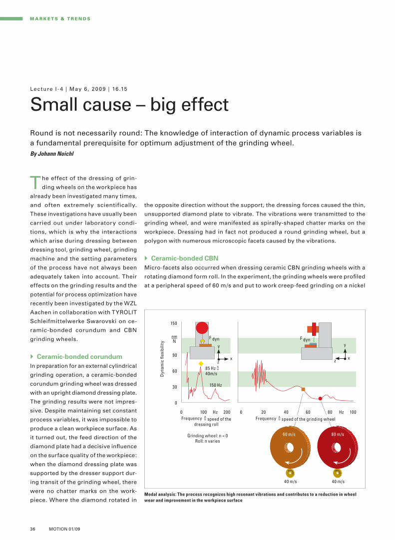
36 MOTION 01/09
Lec ture I - 4 | May 6 , 20 09 | 16 .15
Small cause – big effect
M A R K E T S & T R E N DS
Round is not necessarily round: The knowledge of interaction of dynamic process variables is a fundamental prerequisite for optimum adjustment of the grinding wheel.By Johann Noichl
the opposite direction without the support, the dressing forces caused the thin,
unsupported diamond plate to vibrate. The vibrations were transmitted to the
grinding wheel, and were manifested as spirally-shaped chatter marks on the
workpiece. Dressing had in fact not produced a round grinding wheel, but a
polygon with numerous microscopic facets caused by the vibrations.
Ceramic-bonded CBN
Micro-facets also occurred when dressing ceramic CBN grinding wheels with a
rotating diamond form roll. In the experiment, the grinding wheels were profi led
at a peripheral speed of 60 m/s and put to work creep-feed grinding on a nickel
The effect of the dressing of grin-
ding wheels on the workpiece has
already been investigated many times,
and often extremely scientifically.
These investigations have usually been
carried out under laboratory condi-
tions, which is why the interactions
which arise during dressing between
dressing tool, grinding wheel, grinding
machine and the setting parameters
of the process have not always been
adequately taken into account. Their
effects on the grinding results and the
potential for process optimization have
recently been investigated by the WZL
Aachen in collaboration with TYROLIT
Schleifmittelwerke Swarovski on ce-
ramic-bonded corundum and CBN
grinding wheels.
Ceramic-bonded corundum
In preparation for an external cylindrical
grinding operation, a ceramic-bonded
corundum grinding wheel was dressed
with an upright diamond dressing plate.
The grinding results were not impres-
sive. Despite maintaining set constant
process variables, it was impossible to
produce a clean workpiece surface. As
it turned out, the feed direction of the
diamond plate had a decisive infl uence
on the surface quality of the workpiece:
when the diamond dressing plate was
supported by the dresser support dur-
ing transit of the grinding wheel, there
were no chatter marks on the work-
piece. Where the diamond rotated in Modal analysis: The process recognizes high resonant vibrations and contributes to a reduction in wheel
wear and improvement in the workpiece surface
Frequency =̂ speed of the dressing roll
Grinding wheel: n = 0 Roll: n varies
150
90
60
30
0
0 100 Hz 200 0 20 40 60 80 Hz 100
F dyn F dyny y
x xz z
85 Hz =̂ 40m/s
150 Hz
Dyn
amic
fl ex
ibili
ty
60 m/s
40 m/s 40 m/s
80 m/s
Frequency =̂ speed of the grinding wheel
L_Vortrag_I4_Noichl_E.indd 36 09.04.2009 17:28:39 Uhr

37MOTION 01/09
[1][1] [2][2]
increase in speed. The realization of these ideas makes very great demands on
the grinding machines in terms of their dynamic rigidity. On top of this, the dia-
mond dressing rolls will have to be used at much higher speeds. This has prompt-
ed the question of whether it would be possible to dress a CBN grinding wheel
at a lower peripheral speed and then to use it at high cutting speeds. This how-
ever is not possible due to the dimensional error arising as a result of the radial
expansion of the grinding wheel.
The ideal relationship between the peripheral speed of the dressing roll and that
of the grinding wheel should be in the region of 0.8. In this way we obtain a rough
wheel surface. This in turn gives good grinding performance and an acceptable
service life for the diamond dressing roll. The use of this dressing speed ratio at
high cutting speeds also requires dressing units with very high spindle speeds.
Surprising result
Now however there has been a surprising result from another experiment with
ceramic CBN wheels. When creep feed grinding hardened ball-bearing steel on the
Blohm AGNETA speed-stroke grinding machine, it was even possible to grind the
workpiece at a cut-
ting speed of 200
m/s and a very low
dressing speed ra-
tio of 0.4 without
causing it any ther-
mal damage. This
result requires fur-
ther verifi cation,
but does indicate
that there is poten-
tial regarding prac-
tical realization.
alloy at a cutting speed of 80 m/s. With
this process setting it was quite impos-
sible, irrespective of the grinding wheel
specifi cation, to produce an accepta-
ble surface on the workpiece. It was
extremely rough and wear on the grin-
ding wheel was extremely high. A mo-
dal analysis of the grinding machine
revealed that both the selected speed
of the dressing form roll and the speed
of the grinding wheel lay within the
range of resonance of the grinding ma-
chine. Because of the resonance of the
grinding machine itself, the dressing
roll produced a polygonal grinding
wheel. When grinding, the micro-facets
broke up and thus generated a high rate
of wear in the grinding wheels and a
poor surface to the workpiece. The so-
lution was to use a dressing speed of
80 m/s. This prevented the resonant
vibrations, and the grinding results
improved immediately.
Higher speed
In practice, ceramic-bonded CBN grin-
ding wheels are normally used at cut-
ting speeds of up to 150 m/s. Efforts
are being made, however, to increase
machining performance by a further
ABOUT THE SPEAKER
Johann Noichl is Manager, Application Technology and in charge of the test center in the precision grinding sector at the Aus-trian Tyrolit Schleifmittelwerke Swarovski KG. Trained as an electrical engineer at the HTL Innsbruck, he has worked since 1974 for TYROLIT in the trials, application technology and marketing sector
[1] Supported: A diamond plate dresses a ceramic-bonded corundum grinding wheel [2] Unsupported: Resonant vibrations from the grinding machine are transmitted
to the workpiece in the form of spiral chatter marks
L_Vortrag_I4_Noichl_E.indd 37 09.04.2009 17:28:40 Uhr

38 MOTION 01/09
M A R K E T S & T R E N DS
cess. The principle of the technique consists of adding high-frequency (16–40 kHz)
oscillations at amplitudes of two to 30 μm in or transverse to the direction of infeed.
In this way, the use of ultrasonics has the effect of signifi cantly reducing feed power,
chip size, wear on the tools and heat generation, and it also improves the quality
of the surface. The ultrasonic oscillations reduce the friction between the chip and
the cutting face of the tool. This leads to thinner chips and thereby to a reduction
in the cutting force and an improved surface fi nish when grinding.
To investigate ultrasonic-assisted grinding, Professor Tawakoli and his team de-
Experiments carried out at the Center
of Competence for Abrasive Tech-
nologies and Precision Workmanship
(KSF) at Furtwangen University of Ap-
plied Sciences demonstrate that ultra-
sonic assistance can optimize processes
when cutting metal with geometrically
defi ned or with geometrically undefi ned
cutting edges. Compared with conven-
tional processes, ultrasonically-assisted
grinding and dressing is a hybrid pro-
Dressing with a static dressing tool and with a rotating form roll
Dressing plate
Single-point dressing diamond
Cup dresser Dressing roll
Ultrasonic-assisted dressing with static dressing tools Ultrasonic-assisted dressing with rotating dressing tools
Grinding wheel
Lec ture I I -1 | May 7, 20 09 | 9 .30
Grinding and dressing with ultrasonics
Additional high-frequency oscillations in the ultrasonic range during grinding and dressing reduce forces, temperature and the wear on tools – and enhance the surface fi nish.
Nature as an example: The
use of ultrasonic amplitudes
optimizes grinding processes
Comparison: Using a static dressing tool, ultrasonic assistance can be integrated relatively easily. Using a rotating dressing tool, as is the case with the form roll, it is
more complicated and calls for both know-how and more complex calculations and equipment
By Prof. Taghi Tawakoli
L_Vortrag_II1_Tawakoli_E.indd 38 09.04.2009 17:31:46 Uhr

39MOTION 01/09
Piezoceramic
converter Booster Sonotrode Workpiece
Dynamometer
face of the grain. However, this smooth surface does not have the ideal gripping
properties for creating chips. In ultrasonic-assisted grinding the grains are broken
into fi ne particles by the low-amplitude ultrasonic oscillations, but not smoothed
out. The small sharp fractures on the contact surface of the grain increase its cut-
ting performance in grinding and this led to 30 to 50 per cent reduction in the
grinding power required in the experiments. In comparison with conventional
dressing the additional high-frequency motion of the dressing tool against the
grinding wheel in the micrometer range is characteristic of ultrasonic assisted
machining. In general, it is relatively easy to integrate ultrasonic assistance with a
static dressing tool. By contrast, it is more complicated with a rotating dressing
tool, such as a form roll, calling for both know-how and more complex calculations
and equipment.
Advantages in grinding and dressing
Grinding power is reduced by 30 to 50 per cent
Improved surface fi nish, reduction of the Rz values by 30 to 50 per cent
The surface structure has a different appearance and a higher contact area ratio
Lower temperatures on the surface
Optimized chip formation process with shorter chips
Less wear to the dressing tools
Better profi le retention
Reduction in grinding power and temperatures
veloped an addressable workpiece
holder. The ultrasonic oscillation chain
consists of a piezoceramic converter, a
booster, a sonotrode and a special work-
piece clamping device (see picture
right). The ultrasonic generator converts
electric current into high-frequency
pulses, which are then converted by a
piezoceramic converter into mechan-
ical oscillations with an ultrasonic fre-
quency of 21 kHz. The sonic amplitude
is amplifi ed by the booster and then by
the sonotrode and is transmitted to the
workpiece, which is connected to the
sonotrode. The resultant oscillations of
the workpiece in the tool-holder reach
an amplitude of between ten and 30 μm
at a frequency of about 21 kHz.
Inspecting the grinding
In numerous inspections of work with a
variety of tools, grinding wheels and
stock, the research team compared
ultrasonic-assisted fl at grinding using
traditional corundum grinding wheels
with conventional fl at grinding. Burn
marks were produced in conventional
grinding. In contrast, the workpiece
ground with ultrasonic assistance dis-
played no sign of thermal damage. The
high-frequency interaction between the
active grains and the high acceleration
of the workpiece in ultrasonic-assisted
grinding simplifi es the material remov-
al process. Chips are more easily re-
moved because micro-cracks in the
contact zone between the grains and the
workpiece propagate more quickly as a
result of the impacts due to oscillation
and positively infl uence the next chip
formation. This reduces grinding forces
and frictional effects. There is less plas-
tic deformation in the contact zone. In
addition, the ultrasonic assistance has
a benefi cial effect on the fi nished sur-
face of the workpiece. It is fi ner and has
a higher contact area ratio.
The KSF researchers achieved similar
positive results with ultrasonically-as-
sisted dressing of conventional and CBN
grinding wheels. With conventional
dressing, the tool smooths out the sur-
ABOUT THE SPEAKER
Prof. Taghi Tawakoli is founder and head of the Center of Competence for Abrasive Technologies and Precision Workman-ship (KSF) at Furtwangen University of Applied Sciences. Prof. Tawakoli has over 130 published papers and six patents to his credit and has a laboratory ideally equipped for research in the areas of grinding technology, superfi nishing, mass fi nishing, cutting of hard materials and milling
Ultrasonic oscillation chain: Example of an experimental set-up
L_Vortrag_II1_Tawakoli_E.indd 39 09.04.2009 17:31:52 Uhr

40 MOTION 01/09
M A R K E T S & T R E N DS
curacy. The implications are high procurement costs and long downtimes for
installation and set-up. A joint project between BLOHM JUNG and Georg-Simon-
Ohm University in Nuremberg comes up with a new approach on how accurate
grinding results can be achieved even with worn dressing tools by using mea-
surement control.
Correction of the tool radius
For contour controlled grinding wheel profi ling with diamonds, a CAD/CAM
system, such as the GRIPS 32 programming system, normally produces the NC
program for the desired grinding wheel profi le. The radius of the dressing tool
is taken into account by the so-called tool radius correction. For dressing sys-
tems with swiveling axis the pivoting angle of the dresser must also be observed
so that correct tool intervention is always guaranteed. If the dressing tool is
worn, the original diamond radius takes on an irregular and blunt shape. The
tool radius correction performed by the control unit which always uses the
ideal unworn diamond radius will lose its effectiveness, resulting in dressing
and processing errors. A dedicated tool correction facility in the NC program
takes tool wear into consideration and ensures that a consistently high level of
process quality is maintained. The direct advantages of this kind of wear com-
pensation are:
In profi le grinding, dressing tools
sharpen the grinding wheel and pro-
duce the desired grinding wheel pro-
fi le. Fixed and rotating diamond tools
are used for this process, particularly
for small lot sizes and reprofi ling of
grinding wheels. These tools are inte-
grated in dressing systems which can
feature up to three CNC axes. Dressing
systems which allow the dressing tool
to swivel around the center of the dia-
mond radius are of particular benefi t.
They enable complicated profi les to be
dressed by a single dressing tool with-
out colliding.
In time, the radius of the diamond cut-
ting edge will wear as a result of grin-
ding wheel dressing. It will lose its ge-
ometry. This geometry error transfers
to the grinding wheel and consequent-
ly to the workpiece. Only regular re-
placement of the dressing tool will
therefore guarantee high process ac-
Lec ture I I -2 | May 7, 20 09 | 10 .15
Compensating professionally
[1][1] [2][2]
[1] Pivoting angle: Requirements for intervention between dressing tool and grinding wheel (R tool radius, pivoting angle, pressure angle)
[2] Wear compensation: For contour-accurate dressing a correcting motion of the dressing tool on three axes (a, b, c) is required
Even worn dressing tools can accomplish accurate grinding tasks, as long as exactmeasuring of the tool cutting edge compensates tool errors directly. By Prof. Wilhelm Schröder
L_Vortrag_II2_Schro der_E.indd 40 09.04.2009 17:33:03 Uhr

41MOTION 01/09
aligned with the dressing contour. The effectiveness of the wear compensation
is increased and the potential of dressing systems with swivel axis is com-
pletely utilized.
Grinding experiments
The functionality of the compensation procedure has been proven by several
grinding experiments. To this end, a grinding wheel was profi led with a 2mm
radius whereby the worn diamond rotates from –30 degrees to +30 degrees.
Through this particular dressing movement the diamond cutting edge is mir-
rored onto the grinding wheel during the dressing process. At the same time,
the calculated wear compensation compensates for every error on the dressing
diamond. Checking the dressing results on a visual coordinate measuring ma-
chine shows that a contour accuracy within the tolerance range of ±2,5μm has
been achieved in spite of the diamond wear and the off-center diamond posi-
tion. If the same experiment is carried out without wear compensation, the
deviation clearly exceeds ±5μm.
Conclusion
Modern control technology facilitates continued use of diamond tools for highly
accurate grinding tasks, even
if they are worn. The service
life of the dressing tools is
therefore extended and at
the same time the grinding
process is stabilized by com-
pensating for the dressing
wear. As a consequence, us-
ers have been given access
to a hitherto untapped poten-
tial for cost reduction and
quality improvement.
Stabilization of process
control
Increase of process accuracy
Increased service life
Minimum downtime
Lowering of procurement costs
In order to be able to compensate the
wear of the dressing tool, the exact
geometry of the diamond cutting edge
must be known. For this purpose, the
dressing diamond is automatically
measured by a measuring probe. With
this reading, the actual shape of the
diamond cutting edge is calculated by
a mathematical process and the form
deviation is made available through the
control. The grinding wheel profi le is
only dressed accurately if the diamond
with its worn cutting edge is aligned
in such a way that grinding wheel and
diamond have a common tangent at
the desired intervention point. At the
same time, the radius deviation has to
be radially compensated on two linear
axes. Wear compensation therefore
requires a correcting motion by three
CNC axes. This shows the distinct ad-
vantage of dressing systems with
swivel axes. The swivelability enables
the worn dressing tool to be perfectly
ABOUT THE SPEAKER
Prof. Wilhelm Schröder is professor at the Georg-Simon-Ohm University in Nuremberg, where he is responsible for the fi elds of Engineering Mechanics, Machine Dynamics and Machine Elements in the Mechanical Engineering Faculty
Accurate dedication to contour: Innovative measuring of dressing diamonds reduces set-up times and increases accuracy
L_Vortrag_II2_Schro der_E.indd 41 09.04.2009 17:33:04 Uhr

42 MOTION 01/09
M A R K E T S & T R E N DS
knowledge about the interactions between process and machine requires long
iteration loops when setting up new processes. Understanding the causes of vibra-
tion phenomena and the prediction of interactions help with the systematic im-
provement of manufacturing processes and machines and support effi cient and
effective design of the production process.
Modeling approach for pendulum and high-speed grinding
The approach chosen for the analysis and prediction of process-machine-inter-
actions in pendulum and high-speed grinding processes assembles the complete
model in two parts. On the one hand, we examine the process regarding the
forces generated during chip removal which are changing continuously. On the
other hand, the machine structure is reacting dynam-
ically to the stimulation. Initially, the models for pro-
cess and machine are built separately and are later
linked by suitable parameters. The key infl uencing
factors are identifi ed; generated forces are calculated
and transferred to a suitable machine model. This
model calculates the displacement of the grinding
wheel with the aid of the stored dynamic characteris-
tics of the machine. The positional deviation is then
transferred to the process model. The next calculation
step takes the modifi ed process conditions into con-
sideration when calculating the dynamic forces of the
process model.
High-speed grinding is characterized by high table
feed rates and low depth of cut, resulting in a large
number of overruns, frequent, very short run-in and
run-out periods and consequently a highly dynamic
performance of grinding forces. The run-in and run-
out periods must therefore be taken into account when
modeling. The transmission factors required for force
simulation are determined on the basis of experiment-
al test runs. In addition, different high-speed grinding
processes are carried out and generated forces, ac-
The German Research Foundation
(DFG) has launched a priority pro-
gram, with the aim of closing the know-
ledge gap regarding the infl uence on the
interaction between machine and proc-
ess. It focuses on the interactions at the
interface between structures and proc-
esses of technical systems. Within the
framework of the program, the WZL in
Aachen is also carrying out in-depth
research on innovative methods and
approaches for predicting the process-
machine-interactions in pendulum and
high-speed grinding processes. Missing
Linked: Key infl uencing factors are identifi ed, emerging forces are calculated
and transferred to a suitable machine model
Maschinensteifi gkeitMachine rigidity
Control cycles Grinding wheel
Machine model
Displacement
Cooling lubricant
Surface
Process parameters
Process model
Forces
Lec ture I I -3 | May 7, 20 09 | 11.0 0
Better understanding of grindingThe WZL (Laboratory for Machine Tools and Production Engineering) is taking part in a research program to predict the interactions between process and machine during grinding.By Dr Christoph Zeppenfeld
L_Vortrag_II3_Zeppenfeld_E.indd 42 09.04.2009 17:35:39 Uhr

43MOTION 01/09
chine characteristics in every operating point. The design of the model is based
on the machine’s CAD data. An FEM is generated through abstraction of machine
components and cross-linking the individual parts. The MBS machine model is
built by mapping of the feeding systems and is verifi ed by comparison with the
measured frequency of compliance operation of the machine. The machine
control reacts to positional deviation of the grinding spindle through induced
forces with a positional readjustment. In doing so, it also infl uences machine
dynamics signifi cantly. The model also takes this factor into consideration.
Conclusion and outlook
On the basis of the modeling method presented the dynamic performance of the
complete system of machine and process can be recorded and mapped over
longer travel distances. Looking at it from a holistic perspective can lead to a bet-
ter assessment of machining results, which can help to identify and avoid critical
processes prior to machining. Further research is still needed. One of the areas
we are currently
working on is fur-
ther detailing of the
models. We are also
expecting a marked
improvement in the
quality of prediction
with the implemen-
tation of additional
factors like cooling
lubricant and the
material to be pro-
cessed.
celeration and structure-borne sound
signals with a sample rate of 20 kHz are
recorded. The data obtained is evalu-
ated and stored in a simulation pro-
gram based in Matlab. Initial compari-
sons of the measured force paths
during run-in and run-out of the grin-
ding wheel using the assumptions
drawn up in the physical analytical
model show a good correlation be-
tween the simulated and measured
force path.
Machine models
Classic fi nite element models (FEM)
describe the behavior of machines in
only one operating point. High-speed
grinding involves long travel distances
with high speeds and accelerations. A
movable, fl exible multi-body simula-
tion model of the high-speed grinding
machine was therefore built for mod-
eling the machine. It is capable of cal-
culating the transmission of force from
movable bodies towards fi xed struc-
tural elements by division of force on
discrete nodes of the model. This ena-
bles the recording of the variable ma-
ABOUT THE SPEAKER
Christoph Zeppenfeld has been head of ‘Production Technology & License Support’ at MAN Diesel SE in Augsburg since January 2009. Until December 2008, he was manager of the Manufacturing Technology Research Area at the Laboratory for Machine Tools and Production Engineering at RWTH Aachen
Movable body
Linear guides
Workpiece table
Control loop z
Control loop y
Control loop x
Actual path New path
ILLUSTRATION OF MACHINE CONTROLMBS MODELSUB-ROUTINE FOR FLEXIBLE CONTACT FORCES
Linear drive with impulse decoupling
Contact forces
Components of the MBS machine model: The system calculates the transmission of force of movable bodies towards fi xed structural elements by division of force on
discrete nodes of the model
L_Vortrag_II3_Zeppenfeld_E.indd 43 09.04.2009 17:35:41 Uhr

44 MOTION 01/09
cosity of the medium and the operating pressure, which is between 3 and 180
bar depending on the application. The split is due to the difference between the
rotor thickness tolerance plus the number and the geometry of the vanes.
Demands on machines and tools
Vane pump and motor characteristics have a direct effect on effi cient process-
ing, as complying with lower component tolerances means more diffi cult, i.e.
more expensive manufacturing techniques. Christian Bauer GmbH + Co. KG of
Welzheim takes on the role of a consultant and specifi c requirements are care-
fully discussed with their customers. Following these discussions, the compo-
nent tolerances have to be increased occasionally.
For effi cient grinding of vane pumps and motors it is imperative that all deter-
mining production factors are examined in depth. It is also important that very
rigid machines are used where the natural frequency of machine and grinding
spindle is far outside the operating frequency range of the grinding process.
This holds true for all movable equipment. When choosing grinding tools, a
suitable abrasive layer must be selected depending on the workpiece and the
grinding material, with ducts for chip removal if necessary. In the past, Christian
Bauer has carried out much development work in order to increase part capac-
ity while at the same time maintaining better quality with regard to dimensions
Vane pumps and motors are dis-
placement devices. After intake,
the medium is enclosed in a defi ned
working chamber and is transported to
the consumer, i.e. piston, accumulator,
hydraulic motor or similar, on the pres-
sure side. During the entire working
stroke the vane is pushed against the
rotor ring by centrifugal force or a vane
ring. Theoretically, the pumped medi-
um cannot escape and the fl ow rate
stays almost constant across the adopt-
ed speed range. Adjusting the rotor ring
radially from zero eccentricity to max-
imum will vary the fl ow rate while keep-
ing the speed constant. This makes
vane pumps and motors clearly supe-
rior to other types of displacement ma-
chines. As rotors and vanes are moving
between two lateral cover panels and
are not allowed to touch, the result is
split fl ow. The fl ow loss is adversely
affected by the size of the split, the vis-
Lec ture I I - 4 | May 7, 20 09 | 11.45
Grinding of components for vane pumps
Manufacturing components for vane pumps and motors demands close machiningtolerances while keeping production costs low.By Dr August Kästner
L_Vortrag_II4_Ka stner_E.indd 44 09.04.2009 17:40:05 Uhr

45MOTION 01/09
Permanently high quality of grinding results
The machine’s response to temperature changes must be taken into considera-
tion if grinding results on a permanently high-quality level within the tolerance
range are to be expected. Appropriate technical equipment should be installed
for this purpose. Another important item is the measuring equipment for each
process step including calibration. Training staff to maintain an individual ob-
servations chart or CAQ system within the realms of operator self-inspection
is instrumental in the early recognition of process risks and intervention in the
machine control or initiating the dressing process if necessary.
Constant documentation of the susceptibility of wearing parts like drives, bear-
ings, bellows, electric sensors etc. is needed for preventative maintenance.
Early replacement of
these wearing parts dur-
ing quiet times will result
in effi cient manufacture
as much as multiple ma-
chine systems and run-
ning without break peri-
ods. Cleanliness and
tidiness, low stock levels,
short cycle times, elimin-
ating waste, constant im-
provements and reducing
set-up time complete the
picture.
and surface roughness and to extend
dressing intervals. The choice of cool-
ant and the supply jets which deliver
the coolant directly to the workpiece
can also signifi cantly affect the grin-
ding result. The question whether it
would be sensible to use oil or emul-
sion in the processes largely depends
on the number of grinding machines
available at the component manufac-
turer’s facility. Lastly, a long-term prof-
itability study will determine whether
a central or stand-alone solution and
whether oil or emulsion should be
used. Christian Bauer has decided on
a central supply of emulsion for all their
machines. This particular technology
has been technically perfected and
works with residual particle sizes of
fi ve to six microns. As a result, the com-
pany is able to handle all kinds of grin-
ding materials from high-speed steel,
100Cr6, sintered steel to other types of
hardened or unhardened steel, with
great success.
ABOUT THE SPEAKER
Dr August Kästner is Managing Director of Christian Bauer GmbH + Co. KG. The Welzheim-based company manufac-tures disc springs and precision parts for vane pumps and camshaft adjustment systems
and motors
Precision parts: Avoiding
fl ow losses in vane pumps
Coolant
Minimize time expenditure,share in the company’ssuccess, training
Work towards accurate manu-facture, dedica-ted measuring equipment
Reliable subcontractors
Minimize expenditure
Production/machines/
equipment/manufacture
Tools
Employees
Cost
of i
nspe
ctio
n/
Insp
ectio
n eq
uipm
ent
Material/unfi nished parts
Operational and
administrative costs
Customer
Product
Price
Introducing innovative concepts through contact with machine
manufacturers, tool manufacturers, research facilities
Well-rounded: Diverse criteria ensure the best products
L_Vortrag_II4_Ka stner_E.indd 45 09.04.2009 17:40:08 Uhr

46 MOTION 01/09
M A R K E T S & T R E N DS
ciently rigid design it contributes to an improvement in roundness and cylindric-
ity and corrects any position errors. There is no need for a special feed attachment
as the machine axes transpose all tangential, radial and axial movements. The
design of the honing tool permits a split into two processing sides. Different
honing stone specifi cations can be used for a variety of processing steps, for
example, a honing stone with rough grain for rough machining on the fi rst process-
ing side and a fi ne grain stone for fi nishing on the second side.
With combined turning-grinding-honing machines it is possible to process ro-
tational symmetrical workpieces from blank to fi nished component on one ma-
chine and in a single clamping. Depending on the required component quality,
combined machining can consist of turning and grinding, turning, grinding and
fi nish-honing, or turning, pre-honing and fi nish-honing.
The combined turning, grinding and honing process improves the surface qual-
Nowadays, the combined turning
and grinding process is the pre-
ferred method for internal cylindrical
machining of hardened components.
It combines the advantages of turning
with those of grinding, i.e. a high
achievable stock removal rate and high
flexibility while maintaining high pre-
cision and surface quality. Over the
past years, the ISF has explored two
further concepts for internal cylindrical
machining: extending the existing
combined machining process by a hon-
ing process and internal cylindrical
peel grinding.
Honing reduces production time
The basic advantages of honing are
reliability, high accuracy and excellent
surface structures. Furthermore, hon-
ing can reduce edge damage caused
by pre-machining, or even rectify it. In
addition, the process induces residual
compressive stress into the surface of
the component which extends the life
of the functional surfaces. Expanding
an existing turning and grinding ma-
chine with a honing facility thus offers
the possibility to reduce production
times and to react fl exibly to quality
requirements.
The honing tool developed specifi cally
for the combined turning-grinding-
honing machine is impressive due to
its simple design without additional at-
tachments for feed or measuring. It is
integral to the machine and in a suffi -
High material removal rate: Process kinematics and contact conditions in internal cylindrical peel grinding
Lec ture I I I -1 | May 7, 20 09 | 14 .0 0
Turning, grinding, honingThe Dortmund Institute of Machining Technology (ISF) examined innovative concepts forcombined machining and internal cylindrical peel grinding.By Prof. Klaus Weinert
Workpiece
Workpiece
axial feed rateworkpiece circumferential speedtotal radial grinding allowanceeffective infeedaxial feed rateeffective contact width
angle of scrubbing zonewidth of smoothing zonespecifi c material removal rategrinding wheel speedworkpiece speedworkpiece diameter
Grinding wheel Grinding wheel
PROCESS KINEMATICS CONTACT CONDITIONS
L_Vortrag_III1_Weinert_E.indd 46 09.04.2009 17:42:20 Uhr

47MOTION 01/09
[1][1] [2][2]
by dividing the grinding wheel into different functions, i.e. a cone-shaped
scrubbing zone for stock removal and a cylindrical finishing zone for perfecting
surface quality.
Contrary to grinding, hard turning is characterized by high fl exibility and high
material removal rates. A comparison with hard turning proves the advantages
of internal cylindrical peel grinding with regard to accuracy and effi ciency. While
internal cylindrical peel grinding uses an electroplated CBN grinding wheel and
grinding oil, the hard turning process is carried out dry with a CBN insert. Chip
formation and the circumferential speed of the grinding wheel have a consider-
able infl uence on the axial force in the process. Axial force in internal cylindrical
peel grinding is ten times as small as in turning while the amount of stock re-
moved stays the same. The high feed rates in turning also lead to higher surface
roughness compared with internal cylindrical peel grinding.
Constant striving for increasing productivity and fl exibility strengthen effi ciency
and competition of a manufacturing business. Demand continues to move towards
smaller lot sizes and an in-
creasing selection of op-
tions while product life cy-
cles are constantly being
reduced. To this end, hard-
fi ne machining is taking on
some of these processing
tasks. Thanks to new con-
cepts like the one described,
the effi ciency of production
processes will continue to
be increased in the future.
ities of the components with each pro-
cess step. The fi nal honing process
creates the surface structure typical for
honing. With the alternative turning-
honing-honing process chain this struc-
ture has already been achieved after
the fi rst honing operation. The struc-
ture shows greater surface roughness
though, which is reduced by fi nish hon-
ing. Both process combinations have a
positive infl uence on the component
shape and the cylindricity error ob-
tained was less than 2 μm in both ca-
ses. However, the turning-honing-hon-
ing process combination did not achieve
the same surface qualities as the turn-
ing-grinding-honing process chain.
Internal cylindrical peel grinding
Internal cylindrical peel grinding also
produces high material removal rates
whilst maintaining excellent surface
quality. In this process a specially
shaped grinding wheel moves along
the borehole by axial infeed. The
amount of stock to be removed is only
set once. This has been made possible
ABOUT THE SPEAKER
Prof. Klaus Weinert has been head of the Institute of Machining Technology (ISF) at the Technical University in Dortmund since 1992 and he is also a member of the research association for manufacturing technologies
Combined machining: [1] Three operations on one machine [2] Rigid honing tool with two processing sides
1st processing side
Turning Honing Grinding
2nd processing side
TWO PROCESSING SIDES
L_Vortrag_III1_Weinert_E.indd 47 09.04.2009 17:42:20 Uhr

New grinding spindles for very high speeds reduce the use of lubricants and increase durability.
250.000 min-1 for small bores
To operate effi ciently, a machine tool spindle must have the appropriate load capacity, rigidity and dynamic run-out. In order to guar-
antee these characteristics even for extremely high speeds, the GMN development department was
faced with extraordinary challenges. Breaking points are reached due to high centrifugal forces, a compact design has to ensure subcritical op-eration with suffi cient distance to the fi rst critical speed, high-precision hybrid bearings have to be designed specifi cally for the demands of high-speed spindles. These challenges were met with the help of current advances in motor technology
and the use of further developed GMN spindle ball bearings. It is now possible to effi ciently grind small
internal geometries with up to 250,000 min-1. The GMN
P rocessing small internal diameters with optimum cutting speeds re-
quires high rotational speeds. New GMN spindle ball bearings with very high speed characteristics permit 250,000 revolutions per minute, for in-stance, with comparatively high spin-dle rigidity and load capacity. Opti-mized lubrication of high-speed spindles offers great potential for in-creasing performance. Furthermore, on-demand minimal lubrication lowers oil consumption and increases service life. In future, integrated data loggers will monitor the condition of the spin-dle, store the operating parameters and guarantee high availability. GMN has a long track record of supplying a wide range of high-frequency spindles with speeds of up to 180,000 min-1. How-ever, around two-thirds of the spindles supplied for internal grinding operate with maximum speeds in the 30,000 to 90,000 min-1 range.
Lec ture I I I -2 | May 7, 20 09 | 14 .45
Intelligent spindles
M A R K E T S & T R E N DS
48 MOTION 01/09
A lot of knowledge in a small space: Intelligent electronics store sensor signals, process them and report any
exceeding of critical values to the overall machine control
To operate effi ciently, a machcapa
antesp
f
abea
interna
By Dr Bernd Möller
Temperature
– bearings
– coil
– coolant
Speed
Tool clamping system
Vibration
SPIDER• Record data• Monitor spindle• Monitor process• Transfer measured data
SERIAL INTERFACE• RS232• RS485• CAN• PROFIBUS
Intelligent spindle unit
Sensors for
Maximum speed: GMN high-frequency
spindles achieve speeds of up to
180,000 min-1
L_Vortrag_III2_Mo ller_E.indd 48 09.04.2009 17:49:28 Uhr

grinding spindles used for this purpose have a comparatively large and rigid mounting – the speed characteristic n·dm amounts to up to 4.5·106 mm/min – and a powerful synchronous motor. Consequently, they are suitable not only for special applications at maxi-mum speeds but can also be used fl ex-ibly and effi ciently in a relatively large rotational-speed range.
Integrated lubrication module
These days, ball bearings with perma-nent grease lubrication or oil/air lubri-cation are predominantly used in main machine tool spindles. Yet both meth-ods have their disadvantages which can be overcome by an innovative micro-dosing system combined with appropriate lubrication strategies. Compared with today’s oil/air lubrica-tion method, a signifi cant reduction of the lubricant quantity necessary is to be achieved and the systematic per-formance limits of grease lubrication, i.e. limited usable life of grease at high speeds and temperatures, are to be exceeded. Minimizing lubricant quanti-ties makes ecological and economic sense. It facilitates the integration of an oil reservoir into the spindle and
Important criteria for investment decisions: Control of lubricant quantity depending
on demand
Synchronous motor: Flexible use of grinding spindles in relatively high rotational
speed ranges
ideally requires no more external components. The problems associated with waste oil disposal are also defused. Operating costs of machine tools can exceed acquisition costs several times over if calculated over a normal life cycle. These costs are therefore a decisive factor for many users when making investment decisions. An integrated lubricant cartridge means that high-maintenance ex-ternal components can be dispensed with. The lubricant reservoir only needs replacing at relatively long intervals. An almost instant dosage of lubricant ensures that the adjustment of the lubricant quantity matches demand based on exact measurements of the bearing. This increases the reliability and effi -ciency of the bearing and reduces the quantity of lubricant needed.
Third generation spindles for machine tool
Spindles are also becoming more and more intelligent. Miniaturized electron-ics which are integrated in the spindle store the sensor signals, process them and report any exceeding of critical values to the overall machine control system. Important operating data can be accessed during the entire running time of the spindle and can be analyzed with regard to optimizing the process, machine and spindle. In addition, the aim is to go for bearing condition mon-itoring and consequently early damage detection, based on these intelligent systems. Evaluating temperature sensors, position sensors and vibra-tion sensors will increase precision and productivity of the production process. Additional sensors, on the other hand, harbor the risk of reduc-ing the availability of the spindle sys-tem further, therefore, as few addi-tional sensors as possible should be employed and for the time being, a more intelligent analysis of available signals should be aimed for.
49MOTION 01/09
ABOUT THE SPEAKER
Dr Bernd Möller is head of the Engi-neering Spindle Technology division at GMN Paul Müller Industrie GmbH & Co. KG in Nuremberg
Dosage element
Speed
Speed
Lubrication control
Bearing monitor
Process forces
Spindle drive
Spindle cooling system
Observer
Mot
or h
eat
Bea
ring
tem
pera
ture
Stator temperature
Coolant temperature
Machine control
Spindle bearing
Quantity of
lubricant
Lubricating
fi lm estimated
Power lossG9L(s)
Spee
d [1
min
]
Cutting speed [m/s]
0 5 10 15 20 25 30 35 40 45
300.000
250.000
200.000
150.000
100.000
50.000
0
Grinding wheel – Ø [mm]
L_Vortrag_III2_Mo ller_E.indd 49 09.04.2009 17:49:35 Uhr
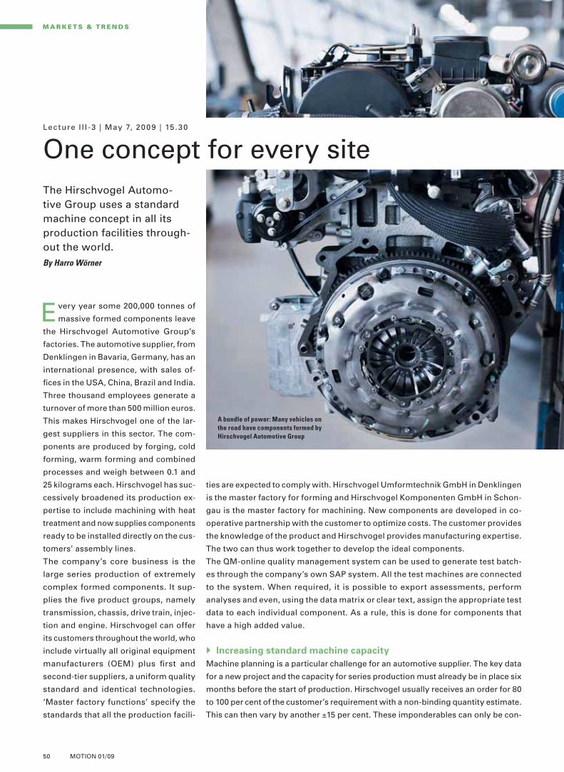
50 MOTION 01/09
M A R K E T S & T R E N DS
ties are expected to comply with. Hirschvogel Umformtechnik GmbH in Denklingen
is the master factory for forming and Hirschvogel Komponenten GmbH in Schon-
gau is the master factory for machining. New components are developed in co-
operative partnership with the customer to optimize costs. The customer provides
the knowledge of the product and Hirschvogel provides manufacturing expertise.
The two can thus work together to develop the ideal components.
The QM-online quality management system can be used to generate test batch-
es through the company’s own SAP system. All the test machines are connected
to the system. When required, it is possible to export assessments, perform
analyses and even, using the data matrix or clear text, assign the appropriate test
data to each individual component. As a rule, this is done for components that
have a high added value.
Increasing standard machine capacity
Machine planning is a particular challenge for an automotive supplier. The key data
for a new project and the capacity for series production must already be in place six
months before the start of production. Hirschvogel usually receives an order for 80
to 100 per cent of the customer’s requirement with a non-binding quantity estimate.
This can then vary by another ±15 per cent. These imponderables can only be con-
Every year some 200,000 tonnes of
massive formed components leave
the Hirschvogel Automotive Group’s
factories. The automotive supplier, from
Denklingen in Bavaria, Germany, has an
international presence, with sales of-
fi ces in the USA, China, Brazil and India.
Three thousand employees generate a
turnover of more than 500 million euros.
This makes Hirschvogel one of the lar-
gest suppliers in this sector. The com-
ponents are produced by forging, cold
forming, warm forming and combined
processes and weigh between 0.1 and
25 kilograms each. Hirschvogel has suc-
cessively broadened its production ex-
pertise to include machining with heat
treatment and now supplies components
ready to be installed directly on the cus-
tomers’ assembly lines.
The company’s core business is the
large series production of extremely
complex formed components. It sup-
plies the fi ve product groups, namely
transmission, chassis, drive train, injec-
tion and engine. Hirschvogel can offer
its customers throughout the world, who
include virtually all original equipment
manufacturers (OEM) plus fi rst and
second-tier suppliers, a uniform quality
standard and identical technologies.
‘Master factory functions’ specify the
standards that all the production facili-
Lec ture I I I -3 | May 7, 20 09 | 15 .30
One concept for every siteThe Hirschvogel Automo-tive Group uses a standard machine concept in all its production facilities through-out the world.By Harro Wörner
A bundle of power: Many vehicles on
the road have components formed by
Hirschvogel Automotive Group
L_Vortrag_III3_Wo rner_E.indd 50 09.04.2009 17:50:44 Uhr

51MOTION 01/09
[1][1] [2][2] [3][3]
[4][4]
[5][5]
Grinding and measuring
For grinding, Hirschvogel uses ma-
chines from a variety of manufacturers
in its internal module. The process that
is needed in each case, for example
centerless cylindrical or non-round
grinding or a combination process, de-
termines the machine that is chosen
for it. Even though the grinding ma-
chines are supplied with the appropri-
ate technology for in-process measure-
ment or for measuring component
alignment, Hirschvogel uses addition-
al forms of analysis and test methods
to determine depth of roughness, twist
and the properties of peripheral areas
in the workpiece, and also uses vibra-
tion analysis. The latter has proven
worthwhile, particularly in the grinding
of roller bearing seats.
Hirschvogel requires the future gen-
eration of grinding machines to offer
a considerably higher
potential for cost reduc-
tion. The machines have
to be able to offer much
greater versatility of use
and the ratio of basic
machines to type-spe-
cifi c investment must be
better, as the batch sizes
and service life of the
products are also in-
creasingly subject to
change.
trolled by having a scalable production
system on the modular principle. Hirsch-
vogel has opted for a standard machine
concept that can produce goods at com-
petitive prices with appropriate automa-
tion. The decision regarding the best
technology for the job is taken during the
course of the project. The machine is cho-
sen and equipped from standard mod-
ules. This enables Hirschvogel to produce
samples by hand that are close to their
series production counterparts. The re-
quired capacity must be installed before
production begins. It is only by this means
that the desired Run@Rate and process
acceptance can be confi gured with the
customer. Capacity is increased by com-
missioning duplicate machines and using
the corresponding automation.
Automation concept
The automation concept is developed
from the value stream planning in each
case. Hirschvogel usually uses stacking
cells or circulating conveyors. The reason
for this is that although direct linking is
usually best for a value stream, it is not
necessarily the most cost-effective solu-
tion in respect of capacity, as the quan-
titative data provided by the customer is
not binding and can vary between zero
and a hundred per cent. Only the cost
calculation at the end of the project
shows whether the automation concept
was actually able to optimize the costs.
ABOUT THE SPEAKER
Harro Wörner Harro Wörner is CEO of Hirschvogel Kompo-nenten GmbH in Schongau. Since 2002, he has been responsible for the global production network for the machining of formed compo-nents within the Hirschvogel Automotive Group
Hirschvogel supplies components for five different groups of products: [1] Chassis [2] Drive train [3] Transmis-
sion [4] Engine [5] Diesel/Gasoline injection
L_Vortrag_III3_Wo rner_E.indd 51 09.04.2009 17:50:45 Uhr

52 MOTION 01/09
M A R K E T S & T R E N DS
Synthetic resin bonding materials are soft grinding universal binders with
phenolic resin and polyimide resin binding agents
Galvanic bonds hold the abrasive in a single-layer coat, the thickness
of which is roughly that of the average grain size used. Tools with this
type of bond cannot be dressed
Metallic sintered bonds are highly wear-resistant
On all grinding tools, the abrasive
material used and how it is bond-
ed are of prime importance. Composi-
tions vary depending on the applica-
tion. Conventional abrasives such as
aluminum oxide (Al2O3) or silicon car-
bide (SiC) are bonded in ceramic or
synthetic resin materials. Super-abra-
sive materials such as CBN or diamond
are additionally secured in metal bond-
ing materials. The type of bonding ma-
terial used and its internal structure
largely determine the grinding and
dressing behavior.
Ceramic bonded CBN grinding
wheels are mainly used in series
and high-volume production. Their
high metal removal rates and
surface characteristics mean that
they are well suited to high-speed
grinding. Dressing is simple
Lec ture I I I - 4 | May 7, 20 09 | 16 .15
Great potential savings
Diagonal grinding with super-abrasive CBN wheels is not dependent on geometry. The process reduces grinding time by up to 80 per cent.
Al2O
3: Abrasives such as
aluminum oxide infl uence
grinding and dressing behavior
TRENDS IN GRINDING TECHNOLOGY
By Udo Mertens
MARKET DEMANDS IN E.G. THE AUTOMOTIVE SECTOR
Lower noise emissions
Lower CO2-emissions
More powerful engines
Lower consumption
Greater reliability
Longer service intervals
Lower purchase prices
L_Vortrag_III4_Mertens_E.indd 52 15.04.2009 14:03:25 Uhr

53MOTION 01/09
to be machined in a single operation. Two grinding processes run simultane-
ously with differing process kinematics. The advantages are:
A shorter grinding feed traverse saves time
Shorter contact length at the fl at shoulder minimizes the
risk of thermal damage
Reduced loads on the edge of the abrasive coating
Even so, there are disadvantages associated with the angular position and the
geometry of the workpiece. A large area of abrasive coating is needed for grinding
the fl at shoulder. Since it does not make economic sense to reprofi le super-abra-
sive grinding wheels, a change of workpiece to one with a different profi le means
that the CBN tool has to be changed as well. This involves a longer idle time. In
addition, CBN grinding wheels with wildly differing geometries have to be kept in
stock – an additional cost factor. This is where diagonal grinding offers great sav-
ings potential. The axis of the workpiece is parallel to that of the grinding spindle.
The angular infeed is achieved by simultaneous movement in the radial and axial
directions. Thus the same tool can be used to grind virtually all geometries on the
circumference and the fl at
shoulder without the need
to change the geometry of
the coating. This is par-
ticularly advantageous for
short runs. Studies by
Saint-Gobain have shown
that the processing time
with diagonal grinding can
be up to 80 per cent short-
er than that required for
straight infeed grinding.
Conventional grinding tools are made
entirely of abrasive material. CBN and
diamond grinding wheels, on the other
hand, have a relatively thin coating of
abrasive that is bonded to a carrier ma-
terial. The choice of this material de-
pends on, among other things, the
grinding job and the conditions of use.
In addition to good thermal conductiv-
ity and vibration damping it must pos-
sess suffi cient mechanical strength.
The following materials are available:
Aluminum
Steel
Synthetic resin, with or
without metal fi llers
Ceramic
Composites
Examples: Camshaft bearings
To date the use of galvanically bonded
CBN grinding wheels for plunge-cut
rough grinding of the bearing points on
a GGG camshaft in a centerless grin-
ding machine has required a support
bushing, seven grinding wheels and
four spacer rings. It is not economi-
cally feasible to dress the single layer
coating of these grinding wheels with-
in a few micrometers. Saint-Gobain
Diamantwerkzeuge GmbH & Co. KG has
therefore developed a grinding tool
with a single carrier material which is
far more durable. All the areas of the
abrasive coating are machined without
re-clamping and there is no need to
dress the profi les. These are more eco-
nomical because they have a longer
tool life and they cost considerably less
to manufacture.
Examples: Crankshaft ends
In practice, shaft ends are machined by
external cylindrical angular infeed
grinding or infeed grinding with a
straight cut. In external cylindrical an-
gular infeed grinding the grinding spin-
dle and workpiece axis are set at a de-
fi ned angle with respect to each other.
The angular position enables high fl at
shoulders and circumferential surfaces
Advantage of angular infeed grinding: Circumference and fl at shoulder are machined simultaneously
ABOUT THE SPEAKER
Udo Mertens is responsible for product management and product development for ceramic bonded CBN and diamond tools at Saint-Gobain Diamantwerkzeuge GmbH & Co. KG
Straight infeed grinding
Angular infeed grinding
GRINDING SHAFT ENDS
L_Vortrag_III4_Mertens_E.indd 53 15.04.2009 14:03:33 Uhr

54 MOTION 01/09
M A R K E T S & T R E N DS
Economic rise and fall
There always have been economic downturns, and there always will be. If a
company depends on a single business sector for its customers, it’s also going
to experience the ups and downs of this sector itself. This is why it is essential
for tool grinding companies to address a wider audience and serve different
sectors. Generally, tool grinding companies have two decisive advantages:
The machine tool mechanic is trained both for the
initial manufacture and for subsequent sharpening
of cutting and machining tools
CNC tool grinding machines are used for sharpening as
well as for the manufacture of various tools in different numbers
In this way, a range of different orders can be secured, accepted and processed
and the growing market for special tools can be serviced. Most of the major tool
manufacturers are not suitably equipped for manufacturing these special tools in
penny numbers. This gives the tool grinding operators a major advantage. Never-
When resharpening a metalwork-
ing tool, the toolmaker has to
decide anew every time whether the
costs of sharpening will exceed the
costs of replacement by a correspond-
ing new tool. Take classic twist drills,
for example, these days, companies
set their own diameter limits below
which sharpening is no longer eco-
nomical. These limits also depend on
the level of automation of the grinding
centers. No matter what the kinematics
are behind the CNC tool grinding ma-
chine: with fi ve CNC axes, almost all
rotationally symmetrical machining
tools can be ground. Here, apart from
the machine’s automatic handling
system, the fl exibility of the clamping
system has a major infl uence on the
economy of the grinding machine’s
operation.
The variety of parts stocked by tool
grinding companies is extensive. One
customer order includes a number of
different drill-bits or mixed types of
tools, on another occasion it includes
a large number of identical special
tools. Given this extreme variation in
orders, quick decisions and skill are
demanded of the cutting tool maker. In
addition there is the maintenance of
short delivery schedules of a week to
a maximum of a fortnight to be consid-
ered – one of the strengths of these
companies. But this is exactly where
the danger lies: with no orders coming
in, the turnover drops immediately.
Advantageous: An order is completed as a rule within a week, but in any case in a maximum of 14 days
Lec ture IV-1 | May 8 , 20 09 | 9 .30
The cutting edge industry: tool grindingIn tool grinding, quick decisions and skill are demanded of cutting tool makers, so that short delivery schedules can be maintained.By Prof. Wilfried Saxler
Receipt of order Delivery date Sales
3–10 working days
ONE STRENGTH OF THE TOOL GRINDING COMPANY IS THE SHORT DELIVERY TIME
Time
L_Vortrag_IV1_Saxler_E.indd 54 09.04.2009 17:54:11 Uhr

55MOTION 01/09
also improves fl exibility and enables crisis situations to be overcome more
easily. Grinding shops are an ideal size for this. They are generally small com-
panies with an average of fi ve employees. A good quarter of them have between
six and fi fteen staff. If a company has a large number of customers, naturally
expenditure on sales and distribution work, logistics and therefore also for ac-
counting rises. But the risk that turnover is suddenly going to plunge is consid-
erably less. Well prepared, the
companies which have provided
for conditions like those men-
tioned above will be able to handle
the diffi cult economic situation.
And any company which has so
far not faced this subject now has
the opportunity to do so. Make
your company fi t for the next eco-
nomic boom – now. Because it’s
on its way...!
theless, the conditions for manufactur-
ing and sharpening a tool are very dif-
ferent (see table).
React fl exibly
The conditions and fi elds of activity
outlined above thus presuppose fl ex-
ibility in every respect. A business can
only be regarded as fl exible if
it can handle differing technical
enquiries on types of tools
it is quick to react to customer
enquiries
in addition to sharpening tools, it
manufactures special tools
it can adjust its tool grinding
machines quickly to perform new
tasks
is a master of grinding technology
it can handle large production runs,
and in particular small runs
For this it will require a large range of
parts, short processing and delivery
times, improved staff productivity,
shorter idle times and a suitably adjust-
able level of automation.
All these criteria can only be achieved
with highly-qualifi ed personnel. Coop-
eration with other grinding companies
Well prepared: Tool grinders are mainly small
companies with between two and five employees
Reassuring: If a company has plenty of customers,
there is less risk that business will suddenly collapse
THE CONDITIONS FOR MANUFACTURING AND SHARPENING TOOLS
Sharpening Manufacturing
Stock material Worn tool (from the customer) Blank (purchased)
Tool drawings Generally not present or required Not available Must be derived and created from the workpiece drawing
Preparations Visual check, cleaning if necessary Shaft preparation Determine amount of wear for grinding stock Dimensioning on measuring machine
Possible edge fracture at the end of the shaft
Clamping accuracy (circular runout)
Dependent on previous history (cannot be infl uenced)
Dependent on blank (can be infl uenced)
Programming expenditure Dependent on geometry Dependent on geometry Control possibility using simulation
Defi ning the position of the tool in the grinding machine
Complicated tool probing operations necessary for helix angel, rotation position, unclamped length, long tooth detection etc. Only detection of the unclamped length necessary Resetting the open-face or cutting face without infl uencing the tool function
Specifi cations according to drawing
Grinding from the solid block
ABOUT THE SPEAKER
Prof. Wilfried Saxler is Managing Director of the Fachverband Deutscher Präzisions-Werkzeug-schleifer (German Precision Tool-grinders Trade Association)
6 to 15 staff27%
over 15 staff 5%
1-man-opera-tions7%
Sales /business risk
Logistic /accountancy expenditure and ancillary costs
2 to 5 staff 61%
SIZE CLASSIFICATIONS OF GERMAN TOOL
GRINDING COMPANIES
AN INCREASE IN CUSTOMER NUMBERS OFFERS
BETTER SECURITY IN TIMES OF ECONOMIC
FLUCTUATIONS
Number of customers
L_Vortrag_IV1_Saxler_E.indd 55 09.04.2009 17:54:12 Uhr

56 MOTION 01/09
M A R K E T S & T R E N DS
Lec ture IV-2 | May 8 , 20 09 | 10 .15
Many axes ensure success
which in turn results in effi cient manufacture of high accuracies whilst maintain-
ing complex geometries.
Innovative high-performance drills
Among the machining processes drilling is an important one because of its 40-per-
cent share of production time. In addition, solid drilling when processing pilot holes
as a fi rst process step is a determining factor in the achievable fi nal quality. Con-
sequently, innovative high-performance drills like the MAPAL MEGA Quadro-Drill
or the MEGA-Deep-Drill have to guarantee high cutting values and have to provide
excellent results for roundness, straightness and diameter tolerance. That is why
MAPAL is using modern multi-axis grinding machines with the appropriate software
in its production processes. Only these machines are capable of processing the
specifi c geometries which are
responsible for chip formation
and cutting behavior of the drill
in a single clamping.
Apart from the margins which
are situated directly behind the
cutting edges, the MEGA Quad-
ro-Drill and the MEGA Deep
Drill have two additional guid-
ing margins which have con-
stant contact with the wall of the
hole created while drilling. As a
result, roundness and straight-
ness of the hole produced are
considerably improved. The
specifi c geometry also opti-
mizes self-centering and brings
advantages when exiting drill
holes at an angle. Due to the ad-
ditional support, the drill oper-
ates very quietly even with in-
creased cutting rates for steel
and cast materials. The deep-
New, specially developed tools are
often an important infl uence on the
success of a product because high-
performance tools help to transform
machine effi ciency into high-quality
products. Grinding in particular plays a
central role in the effi cient manufacture
of innovative tools. Highest precision
– reliable and guaranteed to be repro-
ducible – is virtually a basic require-
ment. The multi-axis design of the
grinding machine furthermore ensures
the complete machining of high-per-
formance tools in a single clamping,
MAPAL high-performance drilling tools
Without multi-axis precision grinding machines there would be no modern high-performance tools. MAPAL Dr. Kress KG is relying on this technological advantage.By Dr Dieter Kress
4 cutting edges for twice the feed rate
4 margins for better drilling quality
Drilling and reaming – one operation
Deep hole drilling up to 30×D
MAPAL GIGA-Drill
MAPAL MEGA Quadro-Drill
MAPAL MEGA Drill-Reamer
MAPAL MEGA Deep-Drill
L_Vortrag_IV2_Kress_E.indd 56 09.04.2009 17:59:26 Uhr

57MOTION 01/09
quire around 20 per cent less torque than conventional twist drills with feed rates
remaining the same. This means that the cutting speeds for cutting steel with up
to 200 m/min can be doubled with tool life travel remaining the same.
Modern reamers
Modern multi-fl ute reamers signifi cantly reduce processing times for precision
drilling through high cutting speeds and very high feed rates. MAPAL sets new
standards in this area with its high-performance reamers. In order to guarantee
utmost precision in the μm range on all levels of the high-performance reamers,
the complete cutting geometry including all angles of the entire tool has to be
fi nished in one clamping following the cylindrical grinding process. Only multi-
axis grinders with measuring systems and in-process dressing facilities can solve
this task effi ciently. The same applies to PcBN reamers or cutters employed in
machining cast materials or in hard machining. When grinding PcBN, oscillating
axes as well as compensation of wheel wear should be preset, in order to avoid
clogging and scoring of the grinding wheels.
The new MAPAL reamers are equipped with PcBN cutting edges even in the di-
ameter ranges of less than 6 millimeters. In this instance, PcBN is applied to the
front face and reproduc-
es the entire cutting ge-
ometry, resulting in big
advantages of tool life
compared with conven-
tional carbide reamers.
When hard machining a
hole with Ø 2.4 H7,
MAPAL managed to in-
crease the output of a
carbide reamer from
around 50 holes to over
1,300 holes with the
PcBN reamer.
hole drill has specifi c fl ute geometries
and fl ute angles which provide good chip
clearance. Chips roll up tightly without
jamming and are removed safely even
from great drilling depths thanks to high-
ly polished surfaces.
The MAPAL MEGA drill-reamer com-
bines drilling and reaming in a single
operation. The process combines dou-
ble-edged drill geometry with up to six
reaming margins for fi nish machining
the bore. The reaming margins protrude
radially by a few hundredths of a mil-
limeter above the drilling margins, re-
sulting in a defi ned reaming allowance.
In contrast, the drilling margins are in
front of the reaming margins along the
axis. Universally designed for use with
steel, cast iron and aluminum, the MEGA
drill-reamer has an excellent self-center-
ing ability and is an extremely effi cient
tool for pinhole drilling.
The latest development in MAPAL’s
solid carbide range is the MEGA Speed
drill. With its innovative face geometry,
it guarantees safe chip control, reduced
feed force and excellent self-centering
ability. As the guidance lands are no
longer arranged on opposite sides, the
drill can no longer get jammed in the
hole. Measurements show that due to
reduced friction MEGA Speed-Drills re-
ABOUT THE SPEAKER
Dr Dieter Kress is managing director of MAPAL Dr. Kress KG. The company specializes in precision tools for metal working; it is the headquar-ters of the MAPAL group which employs more than 3,000 staff in 20 different countries
View of the MAPAL production facility: Multi-axis grinding technology for high-performance tools Utmost precision: MAPAL high-performance drilling tools
L_Vortrag_IV2_Kress_E.indd 57 09.04.2009 17:59:26 Uhr
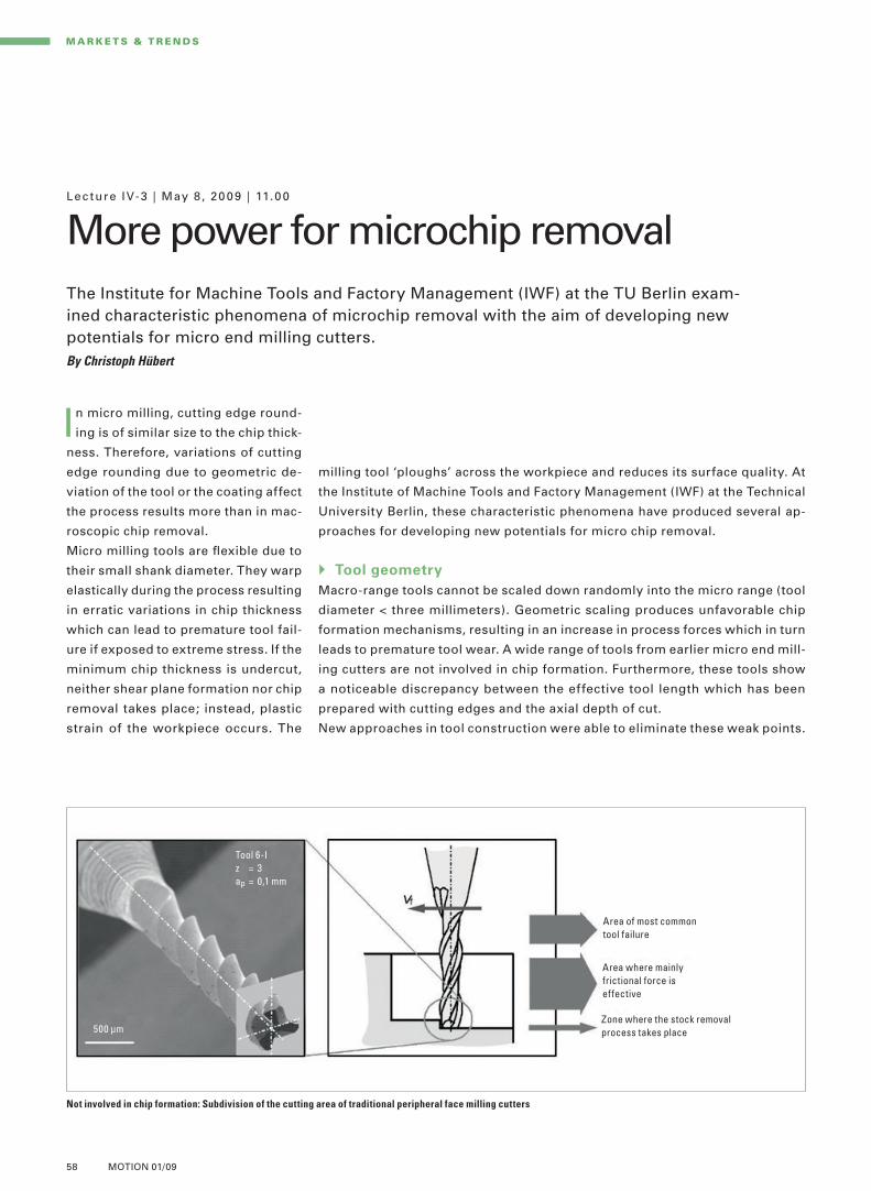
58 MOTION 01/09
Lec ture IV-3 | May 8 , 20 09 | 11.0 0
More power for microchip removal
M A R K E T S & T R E N DS
The Institute for Machine Tools and Factory Management (IWF) at the TU Berlin exam-ined characteristic phenomena of microchip removal with the aim of developing new potentials for micro end milling cutters.By Christoph Hübert
milling tool ‘ploughs’ across the workpiece and reduces its surface quality. At
the Institute of Machine Tools and Factory Management (IWF) at the Technical
University Berlin, these characteristic phenomena have produced several ap-
proaches for developing new potentials for micro chip removal.
Tool geometry
Macro-range tools cannot be scaled down randomly into the micro range (tool
diameter < three millimeters). Geometric scaling produces unfavorable chip
formation mechanisms, resulting in an increase in process forces which in turn
leads to premature tool wear. A wide range of tools from earlier micro end mill-
ing cutters are not involved in chip formation. Furthermore, these tools show
a noticeable discrepancy between the effective tool length which has been
prepared with cutting edges and the axial depth of cut.
New approaches in tool construction were able to eliminate these weak points.
In micro milling, cutting edge round-
ing is of similar size to the chip thick-
ness. Therefore, variations of cutting
edge rounding due to geometric de-
viation of the tool or the coating affect
the process results more than in mac-
roscopic chip removal.
Micro milling tools are fl exible due to
their small shank diameter. They warp
elastically during the process resulting
in erratic variations in chip thickness
which can lead to premature tool fail-
ure if exposed to extreme stress. If the
minimum chip thickness is undercut,
neither shear plane formation nor chip
removal takes place; instead, plastic
strain of the workpiece occurs. The
Not involved in chip formation: Subdivision of the cutting area of traditional peripheral face milling cutters
Area of most common tool failure
Area where mainly frictional force is effective
Zone where the stock removal process takes place
Tool 6-Iz = 3ap = 0,1 mm
500 μm
L_Vortrag_IV3_Hu bert_E.indd 58 09.04.2009 18:00:59 Uhr

59MOTION 01/09
Reference structures with varying machining results: Hardened powder metallurgy steel (1.2379, 54 HRC)
and brass (CuZn39Pb3) have proved to be a suitable sample material. Fluted microstructures for deep
milling and simple surfaces for the fi nishing process are used as reference structures
at their disposal as well as the
HELICHECK PLUS measuring sys-
tem developed by WALTER which
includes high-resolution cutting
edge measuring sensors. The
measurement of process force is
an established and significant pa-
rameter in the characterization of
process behavior for procedures
involving the geometrically unde-
fined cutting edge. The IWF uti-
lizes the evaluation of internal
drive signals of linear direct drives
of the main thrust axes in order to
maintain a database for the ef-
fects of varying process param-
eters and grinding tool specifica-
tions for typical tool grinding
operations, in spite of existing
limitations of data collection.
Apart from the geometric charac-
teristics, the process parameters
of the grinding operation infl uence
the rigidity of the micro tools and
also, indirectly, the process reliab-
ility of the chip removal process.
The IWF investigated the quantifi -
cation of this relationship. First,
the effect of cylindrical grinding of
carbide on the rigidity was analyzed. With micro tools, the machining of the
diameter takes up most of the chip volume and the machining time at the cutting
edge and the transaction piece. Secondly, the effect of the cutting edge on the
rigidity of solid carbide tools was studied. The grinding operation determines
the edge-holding property and the rigidity of the tool through shape and qual-
ity of the cutting edge and the underlying edge.
Use of micro cutting tools
Currently, the IWF is studying the high-precision milling process in terms of
its effects on the structure of machine tools. Apart from a better understand-
ing of the process/machine tool behavior, the objectives are the development
and application of a forecast model for predicting these interactions and to
establish a basis for:
manufacturing microstructures
while observing tight
tolerances and high surface
requirements and
guidelines for design and
confi guration of the
machine tool structure in
terms of optimization of
design and topology
Parameterization of the tool geometry,
for example, enables automatic gen-
eration of different geometry charac-
teristics and the use of the finite ele-
ments method for optimizing tools
according to demand. This makes the
manufacture of milling tools with vary-
ing diameters and geometric charac-
teristics much simpler as the geomet-
ric data can be entered directly into
the machine tool used for manufac-
ture. Workpiece-dependent optimiza-
tion can now be carried out quickly
and simply by varying the geometric
characteristics.
Manufacture
The manufacture of solid carbide
shank tools with diameters < three mil-
limeters requires state-of-the-art ma-
chine technology for both tool grin-
ding and tool measuring. The IWF has
a Schütte 5-axis tool grinding center
ABOUT THE SPEAKER
Christoph Hübert is chief engineer at the Institute for Machine Tools and Factory Management at the Technical University Berlin
Detail: fl ute base
Overall view
Detail: fl ute base
Overall view
Detail: fl ute base
Overall view
L_Vortrag_IV3_Hu bert_E.indd 59 09.04.2009 18:00:59 Uhr
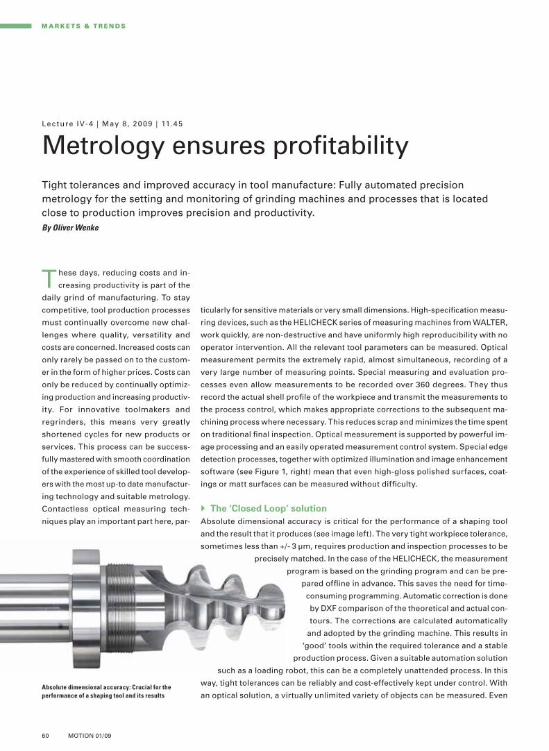
60 MOTION 01/09
Lec ture IV- 4 | May 8 , 20 09 | 11.45
Metrology ensures profi tability
M A R K E T S & T R E N DS
Tight tolerances and improved accuracy in tool manufacture: Fully automated precisionmetrology for the setting and monitoring of grinding machines and processes that is located close to production improves precision and productivity.By Oliver Wenke
ticularly for sensitive materials or very small dimensions. High-specifi cation measu-
ring devices, such as the HELICHECK series of measuring machines from WALTER,
work quickly, are non-destructive and have uniformly high reproducibility with no
operator intervention. All the relevant tool parameters can be measured. Optical
measurement permits the extremely rapid, almost simultaneous, recording of a
very large number of measuring points. Special measuring and evaluation pro-
cesses even allow measurements to be recorded over 360 degrees. They thus
record the actual shell profi le of the workpiece and transmit the measurements to
the process control, which makes appropriate corrections to the subsequent ma-
chining process where necessary. This reduces scrap and minimizes the time spent
on traditional fi nal inspection. Optical measurement is supported by powerful im-
age processing and an easily operated measurement control system. Special edge
detection processes, together with optimized illumination and image enhancement
software (see Figure 1, right) mean that even high-gloss polished surfaces, coat-
ings or matt surfaces can be measured without diffi culty.
The ‘Closed Loop’ solution
Absolute dimensional accuracy is critical for the performance of a shaping tool
and the result that it produces (see image left). The very tight workpiece tolerance,
sometimes less than +/- 3 μm, requires production and inspection processes to be
precisely matched. In the case of the HELICHECK, the measurement
program is based on the grinding program and can be pre-
pared offl ine in advance. This saves the need for time-
consuming programming. Automatic correction is done
by DXF comparison of the theoretical and actual con-
tours. The corrections are calculated automatically
and adopted by the grinding machine. This results in
‘good’ tools within the required tolerance and a stable
production process. Given a suitable automation solution
such as a loading robot, this can be a completely unattended process. In this
way, tight tolerances can be reliably and cost-effectively kept under control. With
an optical solution, a virtually unlimited variety of objects can be measured. Even
These days, reducing costs and in-
creasing productivity is part of the
daily grind of manufacturing. To stay
competitive, tool production processes
must continually overcome new chal-
lenges where quality, versatility and
costs are concerned. Increased costs can
only rarely be passed on to the custom-
er in the form of higher prices. Costs can
only be reduced by continually optimiz-
ing production and increasing productiv-
ity. For innovative toolmakers and
regrinders, this means very greatly
shortened cycles for new products or
services. This process can be success-
fully mastered with smooth coordination
of the experience of skilled tool develop-
ers with the most up-to date manufactur-
ing technology and suitable metrology.
Contactless optical measuring tech-
niques play an important part here, par-
Absolute dimensional accuracy: Crucial for the
performance of a shaping tool and its results
L_Vortrag_IV4_Wenke_E.indd 60 09.04.2009 18:02:39 Uhr

61MOTION 01/09
[1][1]
[2][2] [3][3]
cess. The size of the radii and the resulting sensitivity of the cutting edge require
special measuring procedures. The development of the cutting edge rounding
sensor (see Figure 3 above) opens up the possibility of accurately measuring μm-
fi ne face and contour cutting edge roundness on metal removing tools. This new
option can be used to determine the entire microgeometry of a cutting edge and
all the other profi les on microcomponents. The combination of a number of cam-
eras simplifi es orientation on the tool and thus contributes to accurate, compre-
hensible and reproducible determination of the measuring point. This is also pos-
sible even if the tool has been unclamped in the meantime. There is no need for
time-consuming manual pre-positioning. The measuring process lasts less than a
minute, with the actual measuring time being a mere 15 to 20 seconds. The rest of
the time is needed for the sensor to approach the component being measured. The
relationship with the other sensors ensures that measurements are absolute. In
addition to the radius, width and form of the cutting edge the system also deter-
mines its exact position on the tool.
Summary
The WALTER HELICHECK is a com-
plete system for all measuring tasks.
Tool grinders benefi t from cost-
effi ciently monitored production
and can therefore react quickly and
reliably to their customers’ wishes.
For both one-person businesses
and large companies, the potential
savings are enormous and continue
to rise as the variety of tools in-
creases.
shafts and diamond dressing rolls can
be measured without the need for ad-
ditional setting-up time. The optional
lighting table extends the potential ap-
plications to the measurement of non-
rotationally symmetrical forms such as
profi le sheets or indexable inserts. With
standard tools too, the measure-grind-
measure control circuit has a benefi cial
effect on tool optimization. It contributes
to improvements in cutting behavior,
tool performance and tool life.
Faster and more economical
If the geometry of the cutting edges is
optimized, the effect on machining char-
acteristics is highly benefi cial. Excellent
edge stability, fewer fractures and long-
er tool life make for improved machining
quality and quiet running at high metal
removal rates. The trend is towards
lesser rounding of edges and some
asymmetrical radii. Another reason why
the cutting edge radius was previously
generated in a rather random way was
because it was diffi cult to measure the
result precisely and draw conclusions
that could be incorporated into the pro-
ABOUT THE SPEAKER
Oliver Wenke is Headof the Measuring Technology Develop-ment Center at Walter Maschinenbau GmbH in Garbsen near Hanover, Germany
Advances: [1] Before-and-after results of the HELICHECK image enhancement system [2] Using optimally measured wheel sets on the HELICHECK, the fi rst tool is
usually already within the standard tolerance [3] The cutting edge rounding sensor enables accurate measurement of surface and contour cutting edge roundness
on metal-removing tools with μm precision
L_Vortrag_IV4_Wenke_E.indd 61 09.04.2009 18:02:39 Uhr

62 MOTION 01/09
M A R K E T S & T R E N DS
Lec ture V-1 | May 8 , 20 09 | 14 .0 0
Process optimization using simulation
tolerance. The microgeometry is defi ned by the geometry of the grains and their
arrangement. In the case of engineered grinding tools, where it is assumed that
the grains are in defi ned positions, their actual locations are defi ned by the un-
certainty of the positioning process. The coolant and the chips occupy the clear
spaces between the grains. The stochastic tool model is fully defi ned in three
The use of empirical methods with
high-performance cutting tools is
not just time-consuming and expen-
sive, it is complicated by the fact that
many infl uencing factors come into
play simultaneously, making it very
diffi cult to assign the observed effects
and derive rules for them. In contrast,
analytical and digital tools and process
models can provide scientifi cally based
fi ndings.
Modeling
The simulation model for single-layer
abrasive coatings of diamond or CBN
grains consists of a stochastic model
of the tool, a kinematic model of the
process, a material removal model and
a failure and wear model. It enables the
number of active grains, their cutting
surfaces, and the resulting forces, ru-
gosity and service life to be defi ned
and the probability of their survival
under given conditions of use to be
evaluated. It is based on a simplifi ed
description of elementary events, ob-
tained from tests on individual grains
and simplifi ed for the purposes of nu-
merical treatment.
Stochastic model
The modeling for the tool incorporates
its macrogeometric and microgeomet-
ric properties. The macrogeometry is
described using the nominal geometry
of the grinding tool and the associated
Abrasive tool materials: Simulation models at the Swiss Federal Institute of Technology (ETH) in Zurich enable the number of active grains, their cutting surfaces, and the resulting forces, rugosity and service life to be defi ned.
KINEMATIC MODEL
Grinding speed Tool advance speed Workpiece speed
MATERIAL REMOVAL MODEL
Tool-workpiece interaction Rigidities Plasticity
MODEL OF COOLING
SYSTEM
Pressure, quantity Coolant
MODEL OF INDIVIDUAL GRAIN
Kienzle model Clamping forces Hardness
THERMAL MODEL
Temperature rise Thermal conduction
WEAR MODEL
Blunting of grains Grain fracture Jagged grains Clogging of interstices
Cutting data
Coolant fl ow Forces on the grains
Tool geometry
Tool/workpiece temperature
Change in tool
topologyWear
Failure
Proportion of active grains
Workpiece rugosity, chip space
Cutting area of grains
STOCHASTIC TOOL MODEL
Grain morphology Grain pattern Pattern accuracy Size and orientation of grains
Scientifi cally based: A view of the simulation model
By Prof. Konrad Wegener
L_Vortrag_V1_Wegener_E.indd 62 15.04.2009 14:06:42 Uhr

63MOTION 01/09
er hand there must be suffi cient clear space for the
chip that is removed to collect temporarily in the tool.
If overload occurs a greater or lesser proportion of
the grain can break off, or even be completely torn
out of the bonding material. This is taken into account
in the model by load thresholds for the various types
of change in grain geometry. Allowance can thus be
made for macroscopic effects such as clogging, scor-
ing and blunting of the grinding tool.
Behavior of individual grains
In practical cutting with individual grains it is possible
to determine the specifi c cutting force according to
Kienzle from the correlation of the measured process
forces and the scoring that is formed in the workpiece.
The orientation of the grain with respect to the direction
of cut must be noted. The load threshold at which the
grain fractures can be found by increasing the depth of
penetration into the workpiece.
Practical grinding tests have shown that an increase
in the specifi c metal removal rate has an effect on the
rugosity of the workpiece. This is because a higher
load on the active individual grains changes the sur-
face topology of the grinding wheel, depending on
the grain fracture behavior, and therefore changes
the distribution of active grains. Appropriate consideration of grain wear there-
fore has a critical infl uence on the quality of the rugosity that is calculated in
the simulation. At high cutting volumes in particular, the difference between
the numerical simulation and the measurement is greater when there is no wear
criterion. In the simulation model used, the active cutting surface of the grain
is used as the wear criterion. The critical cutting area at which the grain profi le
changes is correct when the measured number of fractured grains on the tool
and the workpiece rugosity are the same as the calculated values.
The change in grinding wheel topology can also be seen in the distribution of
the cutting surfaces of the grains. On tools that have not been ground there are
a few grains that have a large cutting area and these have a considerable infl u-
ence on rugosity.
Summary
The model enables
process and tool data
to be harmonized.
The interaction of
different simple models
and parameter studies
improves our under-
standing of the process
The effects of separate
parameters on complex
processes can be
unambiguously
investigated
cylindrical coordinates by the following
parameters, arranged in order of prob-
ability: grain size, grain shape, grain
orientation and positional deviations.
Material removal
The material removal model reduces
the complex elastoplastic processes
on the grain to the geometric interac-
tion of the abrasive grains with the
workpiece. This enables the new work-
piece surface that is created and its
rugosity to be determined in the mate-
rial removal simulation. Using Kien-
zle’s cutting force model we obtain the
force acting on each individual grain
and, by summation of this for all the
active grains, the process force acting
on the workpiece.
Failure and wear
When designing or selecting a grinding
tool the cutting and movement kine-
matics of the machining process must
be taken into account. On the one hand,
the individual grains must not be me-
chanically overloaded, but on the oth-
ABOUT THE SPEAKER
Prof. Konrad Wegener is CEO of the Swiss company Inspire AG für mechatronische Produk-tionssysteme und Fertigungstechnik and also Head of the Institute of Machine Tools and Manufacturing at the Swiss Federal Institute of Technology in Zurich
Idealized geometry: Grain morphology of diamond and CBN
THEORETICAL CRYSTAL MORPHOLOGY OF
SYNTHETIC DIAMOND
THEORETICAL CRYSTAL MORPHOLOGY OF CBN
Cube/octahedron
Octahedron/tetrahedron
Simulated grain morphology
Simulated grain morphology
Diamond PDA989
CBN ABN800
L_Vortrag_V1_Wegener_E.indd 63 15.04.2009 14:06:42 Uhr

64 MOTION 01/09
Lec ture V-2 | May 8 , 20 09 | 14 .45
Economic hard fi nishing
M A R K E T S & T R E N DS
Shorter product cycles, niche products and site relocations require a high degree of standardiza-tion in plant procurement and plant reusability. This needs to be taken into account in the hard fi nishing of precision components.By Dr Frank Fiebelkorn
quired, for example contour editors designed for the workshop, interfaces for
importing contour data, simulations or the store of in-house knowledge and
skills. In addition to all this, the overall control system guarantees the integration
Optimization of future fi nishing
processes requires an overall view
of the appropriate machine concepts
plus the ability to use advanced manu-
facturing technology. To achieve the
ideal synthesis of high productivity and
versatility, two strategies stand out:
complete machining and combined
processing.
Using a modular machine structure it
is possible to pursue a consistent pol-
icy of complete machining. Often, it is
only by clamping the workpiece once
and for all that the required quality pa-
rameters in respect of surface fi nish
and accuracy of form and position can
be guaranteed. It is the only way to re-
duce throughput times. The machine
systems used in this way bring the func-
tions of a number of special machines
together on just one platform. The most
up-to-date programming and control
modules also contribute to the ability
to machine even non-round profi les or
threads completely without re-clamp-
ing the workpiece (see Figure 1).
Effi cient software modules
The comprehensive StuderGRIND pro-
gramming system is an example of this
type of modern grinding software. Its
modules support the machine operator
in a process-oriented manner and con-
sequently minimize the work prepara-
tion of component manufacture. The
operator can use the functions as re-
Vast potential: The
prototype system for EDM
dressing
L_Vortrag_V2_Fiebelkorn_E.indd 64 09.04.2009 18:07:56 Uhr

65MOTION 01/09
[1] Using specific grinding processes to increase productivity [2] Grain projection after dressing by EDM [3] Combined processes lead to economies in production
Combined processes
Another strategy for increasing productivity is to combine hard fi nishing pro-
cesses on a single machine. This enables the grinding process to meet the high
accuracy specifi cations for close tolerance with guaranteed process capability
and highly specifi ed surface fi nishes. Hard turning scores highly because of the
great versatility of its geometrically defi ned cutting edge. The combination of
the two processes offers the ability to select the most effi cient machining tech-
nique to suit the task in hand.
Combined hard turning and grinding has now established a place for itself for
the manufacture of gears in the chuck, for universal use and for the series
manufacture of precision components that need to be machined between cen-
ters or in a chuck.
Minimizing changeover times
The potential user can therefore choose between a number of ideal process
strategies for machining precision components. In each case, minimizing the
time spent changing over is a particular feature, particularly when batch sizes
are small. Toolholders, for instance, can be machined between driven centers
(see photo 3). It is therefore possible to start by turning both sides of the whole
contour including the tool changer fl ange, and then, without re-clamping, ac-
curately grinding the cones and fl at mountings with great process reliability
using measurement control systems. STUDER has been able to optimize the
internal machining of workpiece-specifi c toolholder bores equally well with
other types of holder with HSK interfaces. The process-specifi c steps of pre-
drilling and fi nish grinding of the bore have led to excellent bore quality param-
eters with deviations of 0.3 μm for roundness, 0.2 μm for straightness, 0.6 μm
for cylindricity and a mere 1.5 μm
for dimensional accuracy.
The philosophy outlined here of
combined hard fi nishing (grinding
and turning) expands the decision
matrix of production planners for
future production processes. It not
only enables hard turning to be
combined with grinding; it includes
milling with driven tools, hard
reaming and honing.
of the operator interface of external
modules such as sensor system pack-
ages, measurement control or handling
systems from third-party suppliers. The
signifi cance of these person-machine
interfaces for programming, setting up
and managing fi nish machining pro-
cesses is increasing all the time.
Productive carbide
machining
Alongside the various traditional meth-
ods, the technology of high speed grin-
ding for carbides and ceramic with
changing form elements on the work-
piece has distinct productivity benefi ts.
The diamond grinding wheels that are
used for this purpose generally have
ceramic or metal-based bonds. The dis-
advantage to be set against their high
wear resistance, however, is that of
dressing. It is very time-consuming and
expensive to profi le and sharpen these
tools, particularly if they have special
contour lines on the abrasive coating.
In cooperation with project partners,
STUDER has therefore initiated a re-
search project to develop a new profi l-
ing and sharpening process using spark
erosion (EDM – Electro Discharge Ma-
chining, see left-hand photo). Initial
studies and process tests have shown
positive potential for profi ling ability
and the creation of suffi cient grain pro-
jection for subsequent grinding (see
photo 2). Further studies will follow,
with a view to industrial application.
ABOUT THE SPEAKER
Dr Frank Fiebelkorn is Head of Product Development, Research and Technology at Fritz Studer AG in Thun, Switzerland
[1][1] [2][2] [3][3]
L_Vortrag_V2_Fiebelkorn_E.indd 65 09.04.2009 18:07:57 Uhr

66 MOTION 01/09
M A R K E T S & T R E N DS
Double face grinding of transverse sides
In double face grinding of transverse sides, the infeed movement is made up of
two components performed by different machine elements: the grinding speed
and infeed speed running lengthways to the workpiece. The overlap-
ping of the infeed movements is responsible for the good
grinding results and evenness of tool loading. Most impor-
tant input parameters in double face grinding of transverse
sides with planetary kinematics are the grinding speed and
the grinding normal force in an axial direction. An increase
in the average grinding speed improves workpiece depth
pattern and surface, while an increase in grinding normal
force in an axial direction increases the depth of grain cut.
This has a negative effect on the surface quality. A decisive
part was played by selection of a suitable lubricant. This
made possible an increase in the metal removal rate by a
factor of three. Including automatic feeding and discharge of
the workpieces, there was an improvement in productivity over-
all of 200 per cent, while all the required tolerances for mass
High-performance ceramic material
has many outstanding properties:
it is very hard and very light, and is
highly resistant to wear, pressure and
heat. Consequently, this material can
be used in conditions where steel or
plastic would not work. In manufactur-
ing technical ceramics it is in particular
fi nishing, using product-specifi c grind-
ing and polishing processes, which
represents a decisive time and cost fac-
tor. Precision production grinding will
be described using four different grin-
ding processes:
Double face grinding of transverse
sides with planetary kinematics
Angular plunge-cut grinding with
centerless technology
Centerless grinding of pump rollers
Cylindrical grinding of ceramic
materials
Lec ture V-3 | May 8 , 20 09 | 15 .30
The fi nal polishIn precision grinding of hard and brittle high-performance ceramics under production conditions, everything depends on the design being suitable for ceramics.
Between centers: Grinding media being
ground on the KRONOS S
50 per cent less production time: Using a three-stage process in angular plunge-cut grinding, the
CeramTec specialists avoid inaccuracies
By Dr Carsten Russner
L_Vortrag_V3_Russner_E.indd 66 09.04.2009 18:12:19 Uhr

67MOTION 01/09
Cylindrical grinding
CeramTec today grinds ceramic insulators for the CFC zirconium oxide high-
performance brake in an HSG process on STUDER S32 machines at a grinding
speed of 125 m/s.
Here too, ceramic-bonded grinding wheels are used. The stock removal rate is
over eight mm³/mms and the G-ratio is better than 1,000. The tolerances achieved
in the diameter in ceramic mass production are less than six μm.
Hard grinding costs and accuracies
In general, the saying ‘the more accurate, the more costly’ does not apply. It
depends much more on a design suitable for ceramics, and the opportunities
these designs offer for hard grinding. Thus centerless plunge-cut grinding is to
be preferred to grinding between centers as in this way an intricate stage of
workpiece clamping is dispensed with. Admittedly this is at the expense of the
achievable tolerances, specially
in coaxial work. It may be as-
sumed that fast automation con-
cepts, higher grinding speeds
and higher grinding normal forc-
es will increase productivity by
a factor of ten. In the manufac-
ture of workpieces with toler-
ances in the μ range, new dress-
ing strategies will certainly play
a decisive role.
production were achieved. The trend is
away from grinding wheels with ex-
treme diameters in excess of 1,200 mm
and towards higher grinding speeds.
Angular plunge-cut grinding
Grinding media of Si3N4 are ground on
KRONOS S machines from MIKROSA.
On these machines, the previous
processing between centers can be sub-
stantially reduced. The grinding tool is
a diamond grinding wheel, while the
dressing roll is a newly-developed dia-
mond form roll from Messrs. Saint-
Gobain Winter. Neither of these has any
problem in maintaining the required tol-
erances. It is a major challenge however
to profi le the grinding wheel: wear of the
dressing roll cannot be measured. This
means that the CNC program miscalcu-
lates the corrections. This then results
in inaccuracies, and to avoid these, the
specialists from CeramTec AG divided
the process up into three stages:
Pregrinding the curved surface
Grinding the face and the
curved surface
Finishing grinding of the
curved surface
In this way, not only was a cmk-factor
of 3.86 achieved for the curved surface,
process time was reduced by 50 per
cent as well.
Centerless grinding
Extreme demands are made of pump
rolls in respect of their stress gradient.
The roll must fall logarithmically from
the center to the faces by 1.7 μm in or-
der to avoid extreme peaks of stress. If
it is required to achieve these gradients
in honing work, the preceding center-
less grinding with ceramic-bonded dia-
mond grinding wheels must lie within
a range of ± 0.002 μm. These toleran-
ces can only be achieved by grinding
in a clamp and the use of ceramic-bond-
ed grinding wheels dressed in the ma-
chine. Here, the dressing is of major
importance.
ABOUT THE SPEAKER
Dr Carsten Russner is Manager Innovation – Business Development in the business sector Systems Technology at CeramTec AG with a focus on product development
[3][3]
[1][1] [2][2]
The CeramTec product variety: [1] Seals made of various high-performance ceramics [2] Wear parts, ground
with a diamond grinding wheel [3] Various special components
L_Vortrag_V3_Russner_E.indd 67 09.04.2009 18:12:20 Uhr

Gauging and control for grinding machines
Leading...
Please visit our website where you will find more detailed information and your nearest Marposs office.
www.marposs.com www.marposs.de www.marposs.ch
...results from the perfect combination
of many factors
Acoustic sensors for grinders
Grinding wheelbalancingsystems
If your targets are: To encrease productivity, To reduce production costs, Then contact us!
L_Vortrag_V4_Graf_E.indd 68 09.04.2009 18:18:38 Uhr

69MOTION 01/09
Aluminum oxide
Aluminum oxide is made from melted bauxite, the basic material in the produc-
tion of aluminum. It is characterized by its white color and in particular by its
hardness and splintering ability. The purity grade lies between 98.5 and 99.5 per
cent. In order to increase the tenacity of aluminum oxide, chromium oxide in
quantities of 0.2 per cent (pink aluminum oxide) or up to 5 per cent (ruby red
aluminum oxide) is added to the melt.
Single crystal aluminum oxide
Single crystal aluminum oxide which is somewhat tougher and therefore splinters
differently to aluminum oxide is produced in a special process. Grinding wheels
made from single crystal aluminum oxide can achieve a very long service life if
used in suitable applications. But the main use of single crystal aluminum oxide is
as support grain and fi ller grain in CBN grinding wheels.
Sintered aluminum oxide
In the early Nineties, a process was developed to manufacture the smallest pure
corundum grains with an average diameter of between 0.0002 and 0.0025 mil-
limeters and to sinter them into blocks. The result was sintered aluminum oxide.
During a controlled sintering process only the grain boundaries of the nano-
Today, users of grinding machines
have a wide choice of abrasive ma-
terials at their disposal. Each of these –
whether aluminum oxide, sintered alumi-
num oxide, CBN or diamond – has a wide
variety of variants. They all have their own
specifi c uses and the crucial problem is
selecting the ideal grinding medium for
each task. Lot sizes, surface quality, fi re
prevention and dressing tool wear play
an important part in this decision.
Grinding media
The following abrasive types are mainly
used today:
Aluminum oxide and single crystal
aluminum oxide
Sintered aluminum oxide
CBN (cubic boron nitriole)
These varieties of corundum are classed
as conventional grinding media; they are
mainly used as a ceramic bond in preci-
sion grinding operations.
Lec ture V- 4 | May 8 , 20 09 | 16 .15
The ideal grinding mediumWhen choosing the best possi-ble grinding medium for a spe-cifi c application there are many parameters to be considered.
Ideal: The right
grinding medium
results in top product
quality
By Walter Graf
L_Vortrag_V4_Graf_E.indd 69 09.04.2009 18:18:39 Uhr
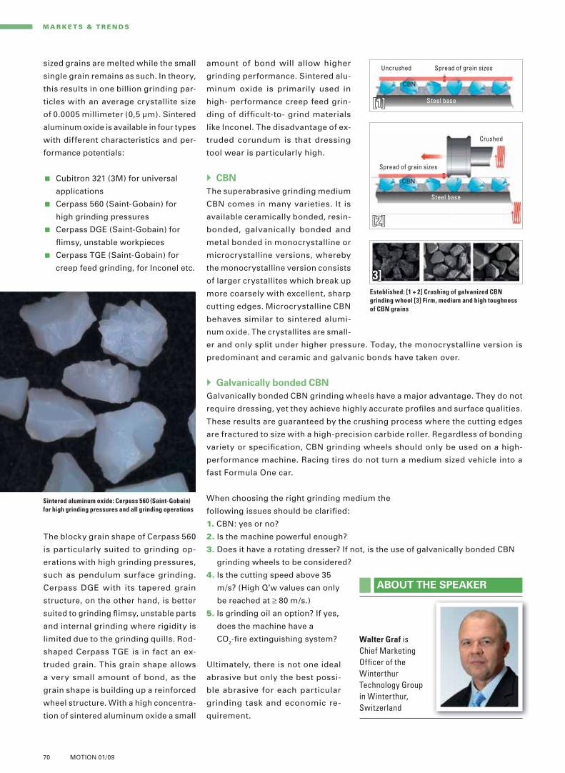
70 MOTION 01/09
GEF_10Jahre_210x287_UK_RZ.indd 1 27.02.2009 10:41:18 Uhr
amount of bond will allow higher
grinding performance. Sintered alu-
minum oxide is primarily used in
high- performance creep feed grin-
ding of diffi cult-to- grind materials
like Inconel. The disadvantage of ex-
truded corundum is that dressing
tool wear is particularly high.
CBN
The superabrasive grinding medium
CBN comes in many varieties. It is
available ceramically bonded, resin-
bonded, galvanically bonded and
metal bonded in monocrystalline or
microcrystalline versions, whereby
the monocrystalline version consists
of larger crystallites which break up
more coarsely with excellent, sharp
cutting edges. Microcrystalline CBN
behaves similar to sintered alumi-
num oxide. The crystallites are small-
er and only split under higher pressure. Today, the monocrystalline version is
predominant and ceramic and galvanic bonds have taken over.
Galvanically bonded CBN
Galvanically bonded CBN grinding wheels have a major advantage. They do not
require dressing, yet they achieve highly accurate profi les and surface qualities.
These results are guaranteed by the crushing process where the cutting edges
are fractured to size with a high-precision carbide roller. Regardless of bonding
variety or specifi cation, CBN grinding wheels should only be used on a high-
performance machine. Racing tires do not turn a medium sized vehicle into a
fast Formula One car.
When choosing the right grinding medium the
following issues should be clarifi ed:
1. CBN: yes or no?
2. Is the machine powerful enough?
3. Does it have a rotating dresser? If not, is the use of galvanically bonded CBN
grinding wheels to be considered?
4. Is the cutting speed above 35
m/s? (High Q’w values can only
be reached at ≥ 80 m/s.)
5. Is grinding oil an option? If yes,
does the machine have a
CO2-fi re extinguishing system?
Ultimately, there is not one ideal
abrasive but only the best possi-
ble abrasive for each particular
grinding task and economic re-
quirement.
sized grains are melted while the small
single grain remains as such. In theory,
this results in one billion grinding par-
ticles with an average crystallite size
of 0.0005 millimeter (0,5 μm). Sintered
aluminum oxide is available in four types
with different characteristics and per-
formance potentials:
Cubitron 321 (3M) for universal
applications
Cerpass 560 (Saint-Gobain) for
high grinding pressures
Cerpass DGE (Saint-Gobain) for
fl imsy, unstable workpieces
Cerpass TGE (Saint-Gobain) for
creep feed grinding, for Inconel etc.
The blocky grain shape of Cerpass 560
is particularly suited to grinding op-
erations with high grinding pressures,
such as pendulum surface grinding.
Cerpass DGE with its tapered grain
structure, on the other hand, is better
suited to grinding fl imsy, unstable parts
and internal grinding where rigidity is
limited due to the grinding quills. Rod-
shaped Cerpass TGE is in fact an ex-
truded grain. This grain shape allows
a very small amount of bond, as the
grain shape is building up a reinforced
wheel structure. With a high concentra-
tion of sintered aluminum oxide a small
M A R K E T S & T R E N DS
ABOUT THE SPEAKER
Walter Graf is Chief Marketing Offi cer of the Winterthur Technology Group in Winterthur, Switzerland
Established: [1 + 2] Crushing of galvanized CBN
grinding wheel [3] Firm, medium and high toughness
of CBN grains
Sintered aluminum oxide: Cerpass 560 (Saint-Gobain)
for high grinding pressures and all grinding operations
Uncrushed
Steel base
Spread of grain sizes
[1][1]
3]3]
Crushed
Steel base
Spread of grain sizes
[2][2]
L_Vortrag_V4_Graf_E.indd 70 09.04.2009 18:18:40 Uhr

Maximum machine availability: with CNCs from Fanuc GEOur CNCs are the most reliable controls in the world: because statistics have demonstrated that the fi rst failure may not happen till 10 years have passed. This will save expensive services and reduce the TCO (Total Cost of Ownership) to a minimum. Your benefi t: highest reliability for maximum availability.
Just one of our strengths.
10 Years Production0 Failures100 % Availability
Fanuc GE CNC Europe S.A.Zone Industrielle / L-6468 EchternachTel.: (+352) 72 79 79 1 / Fax: (+352) 72 79 79 510 [email protected] / www.fanucge.com
Fanuc GE CNC UK Ltd. / 15 Basset Court - Loake Close Grange Park / UK-Northampton NN4 5EZTel.: (+44) 1604 7441 30 / Fax: (+44) 1604 7441 [email protected] / www.fanucge.co.uk
CNC CONTROLS DRIVE SYSTEMS LASER SYSTEMS SERVICE
GEF_10Jahre_210x287_UK_RZ.indd 1 27.02.2009 10:41:18 UhrL_Vortrag_V4_Graf_E.indd 71 09.04.2009 18:18:44 Uhr

Studer Mikrosa GmbH
Saarländer Straße 2004179 Leipzig, GermanyTel: +49-341-4971-0, fax: [email protected], www.mikrosa.com
Studer Schaudt GmbH
Hedelfi nger Straße 13770329 Stuttgart, GermanyTel: +49-711-4014-0, fax: [email protected], www.schaudt.com
Fritz Studer AG
3602 Thun, SwitzerlandTel: +41-33-439-1111, fax: [email protected], www.studer.com
Walter Maschinenbau GmbH
Jopestraße 5 72072 Tübingen, GermanyTel: +49-7071-9393-0, fax: [email protected], www.walter-machines.com
Körber Schleifring Asia-Pacifi c PTE. Ltd.
25 International Business Park#01-53/56 German CentreSingapore 609916Tel: +65-6562-8101, fax: [email protected]
Körber Schleifring Machinery Shanghai Co. Ltd.
Beijing Branch Offi ce
Room 10-04, CITIC Bldg. 19, Jian Guo Men Wai Da Jie Beijing 100004, ChinaTel: +86-10-6595-9934, fax: [email protected]
Schleifring Brasil Ltda.
Av. XV de Agosto, 5.060Sorocaba, Brazil, CEP: 18085-290Tel: +55-15-322457-26, fax: [email protected]
Körber Schleifring France
2 bis, Avenue du Président François Mitterrand91385 Chilly-Mazarin, Cedex, FranceTel: +33-1-697921-21, fax: [email protected]
Körber Schleifring Italia Srl
Via G. Garibaldi, 11822073 Fino Mornasco (CO), ItalyTel: +39-031-926-262, fax: [email protected]
Körber Schleifring GmbH – India Branch Offi ce
No. 99, Spencer Road, First Floor, Frazer TownBangalore 560 005, IndiaTel: +91-80-412504-25, fax: [email protected]
United Grinding Technologies, Inc.
5160 Lad Land Drive Fredericksburg, Virginia 22407, USATel: +1-540-898-3700, fax: +1-540-898-2811
United Grinding Technologies, Inc.
510 Earl Boulevard Miamisburg, Ohio 45342, USATel: +1-937-859-1975, fax: [email protected]
Körber Schleifring UK Ltd.
B13 Holly Farm Business Park, HonileyKenilworth, Warwickshire, Great BritainCV8 1NPTel: +44-1926-4850-47, fax: [email protected]@walter-ag.com
Körber Schleifring
Machinery (Shanghai) Co., Ltd.
No. 1128, Taishun Rd, Anting TownShanghai Jiading 201814, ChinaTel: +86-21-39587333, fax: [email protected]
Schleifring Service AG
Thunstrasse 153612 Thun, SwitzerlandTel: +41-33-439-1212, fax: [email protected]
Schleifring Service GmbH
Hedelfi nger Straße 13770329 Stuttgart, GermanyTel: +49-711-4014-100, fax: [email protected]
Körber Schleifring GmbH
Nagelsweg 33–35
20097 Hamburg
Germany
Tel: +49-40-21107-03
Fax: +49-40-21107-13
www.schleifring.net
Blohm Jung GmbH
Kurt-A.-Körber-Chaussee 63–7121033 Hamburg, GermanyTel: +49-40-7250-02, fax: [email protected], www.blohmjung.com
Jahnstraße 80–82 73037 Göppingen, GermanyTel: +49-716-1612-0, fax: [email protected], www.blohmjung.com
Combitec AG
Lengnaustrasse 12, 2504 Biel, SwitzerlandTel: +41-32-344-0450, fax: +41-32-341-0671 [email protected], www.combitec.ch
Ewag AG
Industriestrasse 4, 4554 Etziken, SwitzerlandTel: +41-32-61331-31, fax: [email protected], www.ewag.com
Mägerle AG Maschinenfabrik
Allmendstrasse 50, 8320 Fehraltorf, SwitzerlandTel: +41-43-3556-600, fax: [email protected], www.maegerle.com
L_Vortrag_V4_Graf_E.indd 72 09.04.2009 18:18:45 Uhr