Embed Size (px)
Citation preview

CHEMICAILRESEAIRCH,.DEVELOPMENT Fi
ENGINEERINGC ENTER CDCC-88
LEAKAGE ASSESSMENT OFPROTECTIVE GAS MASKS
0
cn by David 1. Swift, Ph.D.Charles E. Billings, Ph.D.
L)TIC Frank Shanty, Ph.D.
ELECTE ~ JOHNS HOPKINS UNIVERSITYOCT 1I 98 Baltimore, MD 21205
c~Ib August 1985
U.S. ARMYU
ji. ARMAMENT
"lj : MUNITIONSCHEMICAL COMMAND
Aberdeen Proving Ground, Maryland 21010.5423
88 0O 1 .~*

Disclaimer
The findings in this report are not to be construed as an official* Department of the Army position unless so designated by other* authorizing documents.
Distribution Statement
Approved for public release; distribution is unlimited.
I
4
I
5,
------------------.. . .

SECiRIfy CL, -,iMCATiON OF THIS PAGE
REPORT DOCUMENTATION PAGEia. REPO0RT SEC..XiTY CLASSiFICATION lb RESTRICTIVE MARKINGS
UNCLASSIFIED______________________.a SECURITY CLASSIFICATION AUTHORITY 3 DISTRIBUTION/ AVAILABILITY OF REPORT
It DECLASSIF,CATON/DOVVNGRADING SCHEDULE Apo.e o ulcrlacdistribution is unlimited
4 PERFORMING OiRGANZATION REPORT NUMBER(S) 5. MONITORING ORGANIZATION REPORT NU-106ER(S)
-~ CPDFC-CR-88085
61 NAME OF PERFORMING ORGANIZATION 6b OFFICE SYMBOL 7a. NAME OF MONITORING ORGANIZATIONI (if applicable)
Johns Hopkins University IU.S. Army Research office6-c. ADDRESS (City, State, and ZIP Code) 7b ADDRESS (City, State, and ZIP Cod1e)
615 North Wolfe Street PO o 21Da~itiry-rr- MD 21205 Research Triangle, NC 27709-2221
*Ba. NAME OF FUNDING/ SPONSORING 8b. OFFICE SYMBOL 9. PROCUREMENT INSTRUMENT IDENTIFICATION NUMBERORGANIZATION (if applicable)
CRDEC SMCCR-PPI DAAB-29-81-D-0100Sc. ADDRESS (City, State, and ZIP Code) 10 SOURCE OF FUNDING NUMBERS
PROGRAM PROJECT TASK WORK UNIT
* ~Aberdeen Proving Ground, MDC 21010-5423 EEETN. N.N.ACSINN
% II TITLE (include Security Ciussitication)
N. Leakage Assessmnt of Protective Gas Masks* 12 PERSONAL AUTHOR(S)
Swift, David L., Ph.D.; Billings, Charles E., Ph.D.; and Shanty, Frank, Ph.D.13a. TYPE OF REPORT 113b. TIME COVERED 114. DATE OF REPORT (Year, Month, Day) 15. PAGE COUNTContractor FROM 82 Jul TO 83 pi 1988 Auqjst 145
% 16 SUPPLEMENTARY NOTATION
COP: Will1iam Fri tch, SMCCR- PPI (301) 671-2519
17 COSATi CODES 1B. SUBJECT TERMS (Lontinue on reverse if necessary and identify by block number)
FIELD GROUP SUB GROUP ;>Quantitative fit test,4(-eNT)r15 02 IAerosol test methcd.
Vapor test method. Y ..
1 19 ABSTRACT (Continue orn reverse if necessary an identify by block number)
* This peer group review mreting of respiratory quantitative fit test (QNFr) Wmthods was* intended to consider (1) the advantages and disadvantages of presently used fit test.jmethods, (2) the applicability of present nethods to field effectiveness imasureients,
(3) inrov(,d nethods for determining leakage of respirators, and (4) other research needstput the field of respiratory protection on a firmr scientific footing.
- Boith instrumtentation and ethodology were considered in presentations, discussions andviorkshop sessions as inf~prtant components of fit test measureme~nt. An important concepternmrated early in the mreeting was that fit. tests serve several functions (such asresearch, evaluation, certification, point-of-issue, or field performance) and thatspecific appropriate methods should apply to each need. Thus, new fit test methods andinstruments rmust be designed for determination of field effectiveness since present
(continued on revn.rse)*20 DiST Riau TiON/AVAILABILITY OF ABSTRACT 21. ABSTRACT SECURITY CLASSIFICATION
kjUNCLASSIFiUJ/UNLIMITED Li SAME A~i RPT. 7Qoric USERS UNcLASSIFIED)22a NAME OF RESPONSIBLE iNDIVIDUAL 22b TELEPHONE (include Area Code) 22c. OFFICE SYMBOL
R11DRA J. JOHN'SON (301) 671-2914 SW4CR-SPS-TDO FORM 1473. 84 MAR 83 APR edition may be used unrtil exhausted SECURITY CLASSIFICATION OF THIS PAGE
Ali other editions are obsolete.UNCLASSIFIED
0

e uiCL SIi ISECURITY CLASSIFICATION OF THIS PAGE
19. ABsTRACr (Continued)
mthods are only useable in the laboratory.
The developmnt of respirator fit test methods from fiber filter penetration testirgmethodology involved several assuirtions (such as maximum penetrating aerosol size)that are unproven for respirator leakage testing. There is a need to examine this issue
as well as a need to improve the dilution and calibration methods for both oil and salt
at low aerosol oncentrations.
Fundamental studies of leakage as a function of particle size are needed, with special
attention to ultra-fine particles (0.1 m). The use of aerosol particulates as a
surrogate for vapor leakage needs to be critically examined and tested by simultaneous
leakage measuremnts. Studies of the mixing of air within the cavity of full-face
resoirators are needed to elucidate the effect on leakage measur~Tents and the role of
de_,i,., on rebreathing of mask cavity contents.
Once methods for field effectiveness masurements are developed, these should be applied
to specific instances to obtain a data base for comparison of laboratory and field
reasurerents. Initial studies suggest that present laboratory measurements may not be
good predictors of field performance.
For point-of-use testing (non-intrusive tests) Abere integrity of the mask is maintained,development of accurate, inexpensive, and simple tests are needed. Several approaches
appear to have potential for such measurements and should be investigated.
Both aerosol and vapor test methods for QNFV should be developed, as there are certain
situations where vapor agents are more desirable than aexosols. Feasibility studies of
non-intrusive vapor test rrethods should be supported as a possible field method.
Specific suggestions for needed research are included.
UNCLASTFTED
SECURITV ":.ASSIFICATION OF THIS PAGE
2
l c- ...

-v
% PREFACEThe work described in this report was authorized under
Contract No. DAAB-29-81-D-0100. This work was started in July 1982and completed in September 1983.
A The use of trade names or manufacturers' names in thisreport does not constitute an official endorsement of any commercialproducts. This report may not be cited for purposes of advertisement.
Reproduction of this document in whole or in part is- prohibited except with permission of the Commander, U.S. Army Chemical
Research, Development and Engineering Center, ATTN: SMCCR-SPS-T,Aberdeen Proving Ground, Maryland 21010-5423. However, the Defense
Technical Information Center and the National Technical InformationService are authorized to reproduce the document for U.S. Governmentpurposes.
This report has been approved for release to the public.
,>A-1
.¢.
- °. .4
, °° '-,
0°
L. . ' '- ' - ' " - ' ' ' ' ' ' ' ' " ' ' ' ' '
' "" ' ' ',' '' ' " . ' . ' " ", " ' ',-" % .

9
S
2,2*.
J
'p.
'p.
0 Blank.1
t.
A,
A-
.1*~p.'p.'p.'p
0
S.4-
'p4..-p.
'p.,
* 4-p
0
J :...-;J..J.4d.2...... -'---4-- -~ "4 ,- .. -* A*~* 4 - A *'

CONTENTS
Page
S1. INTRODUCTION 9.....................................9
1.1 Purpose ....................................... 91.2 Definitions ................................... 10
1.2.1 Quantitative Fit Test (QNFT) ................... 101.2.2 Qualitative Fit Test (QLFT) .................... 101.2.3 Fit Factor (FF) ............................. 111.2.4 Protection Factor (PF) ...................... 111.2.5 Factor for Maximum Use Concentration (FMUC) 111.2.6 Worker Use Factor (WUF) ..................... 111.2.7 Effective Protection Factor .................... 111.2.8 Cold DOP (CDOP) ............................. 111.2.9 Thermal DOP (HDOP) ......................... 11
1.3 Overview of Respirator Effectiveness Tests .... 12
2. ELEMENTS OF A RESPIRATOR FIT TEST SYSTEM -
AND OVERVIEW OF METHODOTOGY ................... 15
3. LIQUID AEROSOL METHOD ............................. 26
4. SOLID AEROSOL PARTICLE METHODS ...................... 32
4.1 NaCI .......................................... 32A-2 Uranine ....................................... 35
4.3 BG ............................................ 36
5. REVIEW OF FIELD TESTS FOR IN-MASK EXPOSURES ..... 36
6. GAS OR VAPOR TEST ............................... 44
7. CRITERIA AND POTENTIAL METHODS FOR NON-INTRUSIVE RESPIRATOR QNFT MEASUREMENT ........... 51
8. WORKSHOP ON IMPROVEMENTS NEEDED ON CURRENTMETHODS ....................................... 54
9. WORKSHOP ON NEW METHODS ......................... 56
ii5

CONTENTS (Continued)
Page
10. WORKSHOP ON FIELD EFFECTIVENESS EVALUATION ....... 59
11. WORKSHOP ON NON-INTRUSIVE TEST METHODS .............. 60
12. WORKSHOP ON GAS AND VAPOR TESTS ...................... 61
13. SUMMARY AND CONCLUSIONS .......................... 62
14. RECOMMENDATIONS FOR FUTURE RESEARCH ................. 63
LITERATURE CITED ................................. 67
APPENDIXES
A - MEMBERS OF THE PEER REVIEW GROUP .......... 69
B - PROGRAM AGENDA AND SCHEDULE ................ 73
* C - H. ETTINGER VISUAL AIDS .................... 79
D - METHOD OF DATA ANALYSIS FOR OILPARTICLE PENETRATION ESTIMATE ........... 91
E - NATIONAL DRAEGER MASK FIT TESTER .......... 95
F - NON-INTRUSIVE TEST METHODS ................. 99
G - DEVELOPMENT AND ASSEMBLY OF VAPOR/AEROSOL TEST .......................... 109
H - NEEDED RESEARCH ......................... 129
I - LABORATORY INSTRUMENTATION FOR AEROSOLRESEARCH .............................. 135
6

LIST OF FIGURES
Figure Page
1 DOP Aerosol Size Distribution Reported byEttinger (1983) ................................. 28
2 Effect of "Non-Wearing" on the Effectivenessof Respirator Protection ............................ 33
LIST OF TABLES
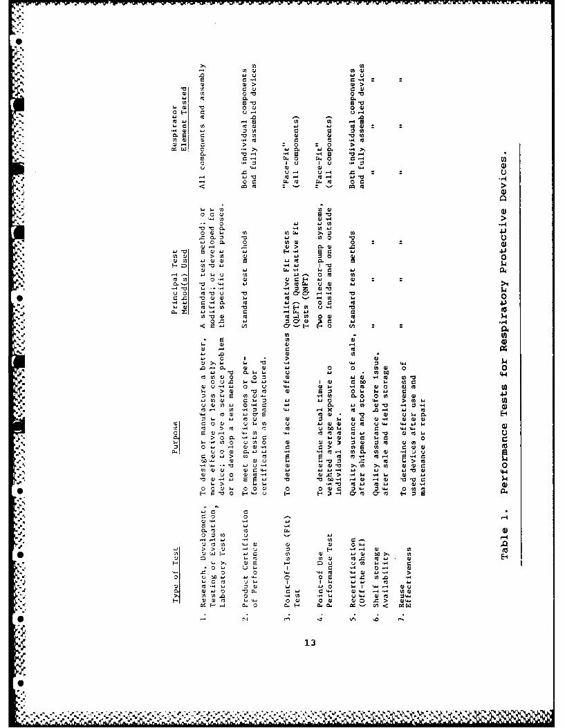
Table Page1 Performance Tests for Respiratory Protective
Devices ........................................ 13
2 Development of U.S. Respirator Test Methods ...... 14
3 Respirator Fit Test Requirements .................... 16
4 Respirator Protection Factors ....................... 17
5 Respirator QNFT - Apparatus and Procedure ........ 19
6 Test Substances .................................. 20
* 7 Generator for Agents ............................. 22
8 Air Supply, Handling, Mixing, and Delivery ....... 23
9 Exposure Volume in Chamber ........................... 24
10 Subject Factors .................................. 25
11 Respirator ....................................... 25
12 Cavity Sampling System ........................... 26
13 Analyzer for Agent Concentration .................... 27
014 Respirator Maximum Use Concentrations ............... 30
7
%a r
r ,r

LIST OF TABLES (Continued)
-Table Page
15 Effect of Off Time on Effective PF.................. 32
16 Results of LASL QNFT on Test Panel.................. 37
17 Effective PP During Actual Use...................... 39
A18 Biological Indications of SCBA PF inBaltimore.......................................... 41
19 SCBA Tests on DOP and NaCl.......................... 42
*20 NIOSH Field Data..................................... 43
21 Test Materials Used for Leakage Tests............... 45
22 Half Mask Penetrations for Fit Test with DOPand NaCl........................................... 49
23 Vapor/Aerosol Leakage CorrelationsParameters......................................... 50
24 Parameters for Non-Intrusive Test Methods........... 51
25 Methods of Non-Intrusive QNFT....................... 53
26 Improvements to Current Methods..................... 57
%

LEAKAGE ASSESSMENT OF PROTECTIVE GAS MASKS
1i. INTRODUCTION
1.1 Purpose.
This report presents the results of a peer group reviewof the current state of quantitative measurement of thepenetration of contaminants through or by the components ofrespiratory protective devices during use. A meeting was heldMarch 24, 25, 1983 under the sponsorship of the U.S. Army as one4 task in a program to assess leakage of protective gas masks.Members of the peer review group are listed in Appendix A. Themeeting agenda and schedule are given in Appendix B.
The purpose of this meeting on the review of respiratorquantitative penetration test methods was:
- To identify and review current and potential futurerespirator quantitative fit test methods.
e To estimate the effectiveness of each current methodin quantifying respirator leakage during field use.
o To identify advantages and disadvantages of eachcurrent method and to define studies necessary toovercome limitations.
e To develop a priority listing of potential new fittest methods for future investigation as an aid toR and D planning.
Although this review has been prepared under U.S. Armysponsorship, it is recognized at the outset that there are many
... user groups in the U.S. who have research and applicationresponsibilities and allied interests in these matters. Many ofthese interested parties are included in the Peer Review Group.These interest groups include:
e Miitary; U.S. Army, U.S. Navy, U.S. Air Force
" Civilian Defense
* Nuclear Regulatory Commission and DOE/National Labs.(NuREG-0041 Respirator Manual)
9
%0
-A. .11L

• NIOSH/OSHA/MSHA
* ANSI; Z-88.2 programs, Z-88.6 medical
e Industrial Users
0 (e.g., L.G. Birkner at Celanese; Steve Dixon andcolleagues at du Pont Haskell Laboratories;K. Ostenstad at John Deere, etc.)
e Manufacturers of Devices (e.g., MSA, AO, Willson,3M, etc.)
4 Manufacturers of Devices (e.g., ATI, Baltimore;Dynatech Frontier, Albuquerque; TSI, Minneapolis)
1.2 Definitions.
1.2.1 Quantitative Fit Test (ONFT).
QNFT is a method including apparatus and procedures forthe measurement of the concentration of an airborne testI substance obtained from samples taken from inside a mask cavityor face piece (Cint), as compared to samples taken serially or
4simultaneously from the ambient space (chamber or hood) outsidethe mask cavity exterior, to the respiratory protective device(Cext). The purpose of the test is to estimate the numericalfraction of material penetrating both the components of therespiratory protective device and the seal (or gasket) madebetween the device and the face, commonly called face fit.Penetration fraction is expressed as (Cint/Cext). This is a
*. laboratory test that may also be used at the point of issue ofthe device for the fitting of individuals, or in their training
* for donning, or use of devices for estimating maintenanceeffectiveness, etc. The QNFT provides an estimate of substancepenetration. Time of testing is typically only a few minutes,with limited head movements.
1.2.2 Qualitative Fit Test (OLFT).
QLFT is a method including apparatus and procedures fordetecting gross penetration or leakage by the use of an irritant,odorant,or other sensory stimulator. It is generally notpossible to estimate the sensory stimulus inside the device interms of a quantitative concentration.
1
" 10

1.2.3 Fit Factor (FF).
See Protection Factor.
1.2.4 Protection Factor (PF).
The PF is defined as Cext/Cint determined from QNFT, alaboratory or point-of-issue (POI) determined value; also calledFit Factor.
1
1.2.5 Factor for Maximum Use Concentration (FMUC).
The FMUC is equivalent to PF as defined above.Permitted Respirator Maximum Use Concentrations are obtained bymultiplying the FMUC by the permissible exposure concentrationappropriate to the specific substance from regulatory or practiceguidelines.
1.2.6 Worker Use Factor (WUF).
WUF is a method for simultaneous measurement of the in-mask cavity (Cint) and exterior workplace (Cext) concentrationsof actual substances2 for estimating respirator as-used breathingzone exposure. The test is conducted in the field using portable(personal) sampling pumps and appropriate collecting devicesarranged to sample Cint and Cext for the contaminant of interest.Typical operating test time would be several hours, such as awork shift, and the result may be expressed as penetrationkCint/Cext) or WUF (1/Pen). This yields time-averaged leakage.Several other definitions expressing different test methods havebeen proposed by NIOSH.
2
1.2.7 Effective Protection Factor.2
WUF corrected for non-wearing of respirato. during use.
i 1.2.8 Cold DOP (CDOP).
CDOP is polydisperse cold compressed air-generateddioctyl phthalate oil aerosol, PDOP (or DOS, DEHS, Corn Oil, etc.liquids).
1.2.9 Thermal DOP (HDOP).
RJ HDOP or monodisperse is thermally-generated dioctylphthalate oil aerosol, MDOP.
11
I ,. . . . . -.-. - - ....- --- - . " ."-"- .

1.3 Overview of Respirator Effectiveness Tests.
It is assumed that readers are familiar with details ofrespirators and their use such as set out by Pritchard. 1 Inreviewing the current state of the respiratory protective devices(respirators) testing, we have identified several significantfactors in test objectives requiring consideration in the designand implementation of test methods (apparatus and procedures) aslisted in Table 1.
Historically, certification for efficiency of removalof particulates, gases, and vapors by respirator air-purifyingelements (filters, adsorbers, absorbers) has been performed instatic chamber tests with simulant challenge substances (leadfume, silica dust, carbon tetrachloride) (Tables 2 and 3).Effectiveness of the assembled system was checked, using anirritant or odorous vapor or dark (coal) dust on test subjects atthe certification lab. In 1960, in an attempt to developrespiratory protective devices for particulates significantlymore toxic than lead, tests were performed on human subjects witha uranine test aerosol. These tests used as a basis the high
* "efficiency all-qlass fiber aerosol filter medium (99.97% removalefficiency on 0.3 pm DOP Smoke). An estimate of the averageleakage was determined from a filter placed in the cavity and
operated for 15-30 min, while subjects pedaled a bicycle.It was found from these tests that leakage was a significantfactor in limiting the ability to achieve the high efficiencyrequired for these devices. In the mid and late 60s, thetechniques of man-testing for leakage were further developed by
the British, using flame photometric determination of solidSodium Chloride (NaCl) aerosol particles, and in the U.S. by LASL(Ed Hyatt, et al.) using light scatter from a DOP liquid particleaerosol. An estimate of instantaneous leakage was recorded for5 min and an average was determined from leakage peak heights.These are laboratory tests that form the basis for a genericrespirator leakage factor. These techniques have subsequently,in the 1970s, been adapted to quantitative fit tests, at the POIof the respirator prior to going to the work place (Table 4). Ingeneral, the DOP and NaCl test procedures do not yield the sameleakage factor for a single individual tested.
Field test data at the point-of-use (POU) onconcentrations of several different workplace substances
" determined simultaneously inside the mask and in the workenvironment during typical work activities, always yield leakageconcentrations considerably greater than those determined by thequantitative face-fit test at the POI.
12
S"X
00 Q) 0 40 H- -
4-'- Em0.0
-,4 fa4-4> 0 04 4
ME- CJ 0 0
S- ( "44 13 44 -44
4 0 :. 0 4
u. *14-4 u -4( 4 4 C..4
0 r0 0 0
0 44- 4 41 (A.
00 0V 0 M0 :0)-4 >-- m4 (4 44
41 ~~ (1 0" 41 4 0( 00
a)4 (44 wj0 0
0) -H4 w r.r4 (44 W .i
04 -, 4 (4- z >t 044 0 ( 443 (D --4-
x 434 c4 -44 440 Z 4 4) 0j
E 4 4 0 1'>
43 4. 4-..- 00. 4.
U)- W4 . (4 Q .- 0 41 (41 H m
0 u 44- w ~ 4.4 C 0 ww(4 -4 w 4 0 u %& 4 03) (4 0 )0 0 oF
0.W0) v4 46J 4 0 4.1 0a)4(n41 0 .4 0- - 0. 41 - w -
.4 .43 V4 m (4o . -
A040 ca 4V w- 0 0 (4 0 0-4._ 0 0 w 0.4w. b u i ).) 0 4 41 wn
ro >M -4to0 00 4c 4 4.4-( U4'00. 1.)-4 4' 4 . 4
> 04 0 44 43. -( 40 4(
0- a)3 0 43 0 4-4. -4 - n )o 'i. > 434- Lo( -40 0(4 H33 .11044 W 4- to -4 4( >0-U
Li3 4- ,4C (v 0. 4.4( c3' 0('n iQ (L *40 C 4- 1W4 (4 &- 4.4 (4
.4H w l 0-4 (44 4)O' (44 *v 10 "a C4->4. w4.4 m " m- w3 4- 434 4
43 TO 0 -0 D 0 0 4.w4c4 z 04 z 4 044.4 (nE- t0 o4- E44( u4( 4 (444 M 4' 4344 M a
4-.~a a) ( 0 3 443 4 0 ( 43(-4 44. > >(40 -4 4
'-4 uO4- w 3 430 w- 4.40 .0 (4 V0 t3 V)44- w. 0i( M40 (44 & 0C4344>~~~ ~~ W4 ( ( 4- 44 0"444~-~0 440. 43 343' >.4 >,4 433
*~ 003.V0 4 0 04) w 0- =(. > ((
4 . . . .... .. . 4% %4 4

Table 2. Development of U.S. Respirator Test Methods.
1. Test Schedules of the U.S. Bureau of Mines
Date Item Certified Schedule No.
1919 Self-Contained Breathing Apparatus (SCBA) 131919 Gas Masks 141927 Hose Masks 191934 Filter-Type Dust Fume, and Mist Respirators
(F-T DFMR) 21
1944 Chemical Cartridge Organic Vapor Respirators(OVR) 23
1965 Modification of F-TDFMR, added the Uranineheadform test 2 lB
I 2. NIOSH/MSHA; Schedules Consolidated. Extended. Recodified
1972 See Table 3 for q"antitative fit-tests(QNFT) in these regulations 30 CFR 11.1 to30 CFR 11.18 3.7
3. Development of Quantitative Fits Tests (Laboratory)
U.S. AEC Respirator Panel Recommendations 1958-59Development of Uranine Test, HSPH, 1960Adaptation of DOP Filter Test to respirators, LASL, 1960-65Incorporate above two new tests into Bureau of Mines Schedule
21B, 1965Development of modified NaCI test, HSPH - 1969-1970In Recodificaton 2 above, NIOSH drops DOP fit and uranineheadform tests, and adds DOP headform test, 1972
- 4. quantitative Fit Tests Currently Used
DOP, DOS, Corn oil liquid particle aerosolsNaCl solid particle aerosols
5. Qualitative Fit Tests Currently Used
Pressure, suction, coal dust, isoamyl acetate (IAA), irritantsmoke, saccharin
14
0je

STable 2. Development of U.S. Respirator Test MethodsS(Continued).
6. Fit Test Methods Summary. 1982
QNFT Methods: Intrusive, objective data, elaborate and
expensive equipmentQLFT Methods: Non-intrusive, subjective data, simple
equipment
All of the above quantitative tests require apenetration through the mask facepiece to extract a sample of theinternal mask cavity concentration. It would be ben.icial if atest involving non-intrusive modifications could be developed.At the same time, there has been no development of generallyrecognized POI or POU tests for vapors. There is no reason toassume that leakage factors for vapors will be the same as
* determined by using aerosol tests.
There also appears to be several research questionsraised by these issues, for example, what is the field-predictivevalue of a POI quantitative face fit? If, as it appears, the POItest is not a good predictor, how should actual field exposuresbe determined?
, The non-intrusive test method would appear to offer a
possibility to solve some of these issues. Types of non-intrusive methods that have been suggested include recoveredsamples (e.g., exhaled alveolar air concentration of a non-absorbed organic vapor), mask cavity real time detector orsampler, light-scattering device viewing interior of cavity foraerosol concentration, and color tape indicator.
These issues and QNFT experience have been reviewed atthe peer group review meeting to provide a base for developmentof a set of mid- and long-range research recommendations forplanning purposes.
2. ELEMENTS OF A RESPIRATOR FIT TEST SYSTEM - AND OVERVIEW. OF METHODOLOGY.
Elements of a respirator fit test system and criteria,available choices, and factors influencing choices are presented
0' in this section. The purpose is to lay out in logical order the
.X
15
0 '.1 ".

Table 3. Respirator Fit Test Requirements.
Numrber ofPeople
Rciqtirccl for Total Time3D CF.R I Subpart Type of F<piecc Test Atmospherc T
est of Test (moin) Exercises Requrcc
H. S.&f-contained Half mask, rff facepeecc. 1000 ppm ;soamlyl 6 2 None requiredbreathing apparats and mutahpluee acetate (I AA)
1,I Gas masks Half mask 100 pptn IAA Not specified 8 Four 2-minute exercise%
to I. 1) )specifiedFull face mask 1000 ~r~ I.AA Nut specified 8 Four 2-minute exercises
specifiedJ, Supplied-a)ir Half masks. rfl race 1000 ppm [AA Not spccified 10 Ts-o 5-minute exercises
* rspirators' masks. hrx~ls, and specirilee* (It. Iz.4 - I(o') helmets 3pc ld3
- ~~k-F'~ Respiawrs approved ftor -Not spcfe 0 Santiblasting exercisessandblasting specified
K, Dust. fume, and mist Half masks, full face For dusts and mists, no fit ttst requiredrespirators masks. hoods, powered Fumes: 2 o seife
TLV above 0.03 mg/rn' and nonpowered 100 ppm IAA Not specified*Single-use respirators for oftesrctie
dust anti mist N i etrqie4TLV bWow 0.05 tog/rn Half mask 100 ppmn lAA Nut spccified 5 2- arid 3-minute exercises
asspeca fled
-1Full face and hrxsds. 1000 pptn lAA Nut spteailicd 5 Santec as half mask. abo'epowvered anti
nonpowerer. sand
mouth pieeJs L, Chemical cartridge: Half masks 100 ppnt IAA Nut specificd B Your 2-minute exercises14respiratorss :1ifei
'4Full face, hood. 1000 ppin IAA Not specified 8 SameT' as half mask. al,Cmouthpieces. pqoweredand nonpowered
M. Pesticide respirators Same as Subpart L. Chemical cartridge respirators
"Tests must be made as follo,'s: (1) 4 cfmt for tight-fitting fazcepieces. 5 cfm for hoods and helme .ts, and (2) 15 cfm for both types.Silica dust is generated under condittons that duplicate sanclbltstitg. Silica dust colicentration is not specified, but dust genntion proKdU8
and stphject actijiiecs airc specificil so the predure cant be tilicater. \Iaximurn altousable SiO, dust within the hqntd -0.32 mg/t%' (TLV forIpercent SiO, 0.?9 mg/it').
16
01 O , I '%

Table 4. Respirator Protection Factors.1
Facepiece2 ProtectionType Respirator Prcssure Factor
I Air-Purify rigA. Particulate 3 removing
Singlc-uC, 4 dusr - 5Quarter-mask, dussr - 5I lalf-mask, dust" - 10I lalF. or Quarter-mask. fume - 10I lalf- or Quarter-mask, I ligh-Effictency" - 10Full Facepiece, High-Efficiency - 50Powered, High-Efficiency, all enclosures + 1000Powered, dust or fume, all enclosures + X 9
B. Gas and Vapor-Removing'°
Half-Mask 10Full Facepiece 50
II. Atmosphere-Supplying
A. Supplied-AirDemand, lHalf-mask - 10Demand, Full Facepiece - 50Hose Mask Without Blower, Full Facepiece - 50Pressure-Demand, I talf-Mask'' + 1000Pressure-Demand, Full Facepiece'2 + 2000Hose Mask With Blower, Full Facepiece 50Continuous Flow, Half-Mask 't + 1000Continuous Flow, Full Facepiece12
+ 2000Continuous Flow, Hood. Helmet, or Suit' 3
2000B. Self-Contained Breathing Apparatus (SCBA)
Open-Circuit. Demand, Full Facepiece 50Open-Circuit, Pressure-demand Full Facepiece + 10,00014Closed-Circuit, Oxygen Tank-type. Full Facepiece - 50
III. Combination Respirator,A. Any combination of air-purifing ind Use minimum protection
atmosphere-supplying respirator. factor listed above forB Any combination of supplied-air type of mode oif operation.
respirator and an SCBA
Exceptin: Combination supplied-air respirators, in pressure-demand or other positivepressure mode with an auxiliar vself-contained air supply, and a full facepiece. shoulduse the PF for pressure-demand SCBA.
4 The overall protection afforded by a given respirator design (and meode of operation) may be
defined in terms of its protection factor (PF). The PF is a measure of the degree of protectionafforded by a respirator, defined as the ratio of the concentration of contaminant in the
ambient atmosphere to that inside the enclosure (usually inside the facepiece) under condi-tions of use. Respirators should be selected so that the concentration inhaled by the wearerwdIl not exceed the appropriate limit The recommended respirator PF's are selection and useguides. and should only be used when the employer has established a minimal acceptablerespirator program as defncd in Section 3 of the ANSI Z88.2-1969 Standard.
17
% _

Table 4. Respirator Protection Factors (Continued).1
In addition to facepieces, this includes any type of enclosure or covering of trhe wearer's
breathing zone, such as supplied-air hoods helmets, or suits.
Includes dusts, mists, and fumes only. Does not apply when gases or vapors are absorbed onparticulates and may be volatilized or for particulate: 'olatilc at room temperature. Example:Coke oven emissions.
' Any single-use dust respirator (with or without valve) no' pecificaJly rested against aspecified contaminant.
5Sin&g!-use dust respirators have been tested against asbestos and cotton dust and could be* ,. assigned a PF of 10 for these particulates.
6Dust filter refers to a dust respirator approved by the silica dust test. and includes all types
of media, that is. both nondegradable mechanical type media and degradable resin-impreg-nated wool felt or combination wool-synthetic felt media.
'Fume filter refers to a fume respirator approved by the lead fume rest. AJI types of media areincluded.
-High-efficiency filter refers to a high-efficiency particulate respirator. The filter must be atleast 99.97% efficient against 0.3 am DOP to be approved.
'To be assigned, based on dust or fume filter efficiency for specific contaminant.
0 For gases and vapors, a PF should only be assigned when published test data indicate thecartridge or canister has adequate sorbent efficiency and service life for a specific gas or vapor.In addition, the PF should not be applied in gas or vapor concentrations that are 1)immediately dangerous to life, 2) above the lower explosive limit, and 3) cause eye irntationwh.n using a half-mask.
''A positive pressure supplied-air respirator equipped with a half-mask facepicce may not beas stable on the face as a full facepiecc. Therefore, the PF recommended is half that for asniLmar device equipped with a full facepiece.
-2 A positive pressure supplied-air respirator equipped with a full faccpice provides eyeprotection but is not approved for use in atmospheres immediately dangerous to life It isrecognized that the facepiece leakage, when a positive pressure is maintained. should be thesame as an SCBA operated in the positive pressure mode, However. to emphasize chai it
0 basically is not for emergency use, the PF is limited to 2,000
i"The design of the supplied-air hood, suit. or helmet (with a minimum of 6 cfm of air) may
determine its overall efficiency and protection. For example, when working with the imisover the head. some hoods draw the contaminant into the hood breathing zone This may beovercome by weanng a short hood under a coat or overalls. Other limitations specified by the
* approval agency must be considered before using in certain types of aimoipheres
h SCRA operated in the positive pressure mode has been "csted on a selected 31 manpanel and the facepicce leakage recorded as less than 0.01% penctraoon Therefore. a PF of10,000- is recommended. A this time, the lower limit of detection 0.01% does not warrantlisting a higher number A positive pressure SCRA for an unknnwv concentration is recom-mended. This is consistent with the 10,000. that is listed. It is essential to have ane-,',n'device for use in unknown concentrations. A combination supplied-air respirator in pressure.demand or other positive pressure mode. with auxiliary self-contained air supply is alsorecommended for use in rinkniowii concentrations of contaminants imnediarly dangerous toifc Other limitations such as skin absorption of HCN or rrirum, must be considered.
18
-- A

elements and factors so that present or proposed methods can bemeasured against a set of suitability conditions.
Table 5 is a list of nine basic elements that wereconsideied, starting with the test-substance. Every fit tostsystem and methodology of testing must include these elements.Major systems and methods used to date will be discussed below,but a new fit test methodology could be assembled by choosingappropriate elements best fitted to a specific task. As detailedbelow, it may be desirable to use a specific apparatus and methodfor a particular type of fit test, such as a field test.
Table 5. Respirator QNFT - Apparatus and Procedure.
Basic Elements
Test Substance (aerosol, gas, vapor)GeneratorAir Supply, Handling, Mixing, DeliveryExposure Volume - ChamberSubject - ProtocolRespiratorSampling System - CavitySampling System - ChamberAnalysis - Measuring ConcentrationData Handling
Table 6 is a consideration of test substances forquantitative fit tests, including both gaseous and particulatematter. The criteria of choice are not prioritized. Both NaCland oil (DOS, DOP, Corn oil, or PEG) meet the criteria for choiceat the top of Table 6, but of the special aerosol criteria listedbelow, oil aerosol is more suitable because of the hygroscopicproperty of NaCl.
Viable aerosol does not enjoy wide use because of thedifficulty of preparation and the method of collection. At thetime it was first developed, it was assumed that only such amethod could enable quantification of very low aerosolconcentration. It now appears that light scattering or flamephotometry have adequate sensitivity to detect concentrations lowenough to obtain fit factors > 10,000.
Several gases and vapors have been used to measure maskleakage. It is not known experimpntally whether such substances
19

behave si..larly to aerosols, with respect to gas mask leakage;but in principle the transport of a dilute vapor is differentfrom an aerosol. Some of the gases used are easily adsorbed bythe mask charcoal and can be used as leakage test agents. Othergases easily penetrate charcoal and must be excluded from theinhalation valve region by providing a separate source of vaporfree air for inhalation. The influence of such "plumbing" on theperformance of a respirator is not known, but is possible thatsuch a mechanical connection can alter the face fit of therespirator. The gases or vapors must be nontoxic at the exposure
-2 concentration and a method of real time analysis that does notrequire large gas volume samples must be available.
Table 6. Test Substances.
2' Function - Indicate Leakage by Transport
'l.y Criteria For Choice
- Non-Toxic-*. Chemically Stable, Non-Reactive
Available, InexpensiveDetectable
Removable by Respirator FiltersAppropriate Leak Surrogate
* Available Choices
Viable Aerosol - B. GlobigiiNon-Viable Aerosol - Oil, Salt, Uranine, OtherVapor - Chlorofluoromethane, Etc.Gas - Helium, Argon, Ethylene, Sulfur Hexafluoride
Penthrane, Amylacetate, Methane
Special Aerosol Criteria
Rel. MonodisperseMinimum Transport, Diff., Sed., InertiaNon-Hygroscopic
0 UnchargedLow Vapor Pressure
,P In addition to the above criteria, aerosols must meet* additional criteria listed in Table 6. If the aerosol is
significantly polydisperse (pg 1.5), the selective leakage
20

(dependent on particle diameter) will generally lead to differentsize distributions on the exterior and interior of the
respirator. Generally, this situation will cast doubt upon themeasured "concentration" ratio for any presently used method ofmeasurement. The appropriate size of aerosol particles toachieve minimum combined transport by sedimentation, inertia, anddiffusion is not known for respirator leakage, since we do notknow either the exact process or the geometry of the leakagepath.
If the aerosol is hygroscopic (such as NaCl), it willundergo water vapor accretion and growth at high relativehumidity (within mask and in respiratory tract). This factorwill change its transport properties. Also, if the aerosolparticles are composed of a liquid of significant vapor pressure,the particles will evaporate. The role of particle electriccharge in respirator leakage is unknown, but it can be theorizedthat if particles are significantly charged (>100 charges/particle) their collection at leakage surfaces will be altered.
Table 7 is a concise listing of generatorcharacteristics for aerosol or vapor generating devices. Thegenerator must have a sufficient output to reach a steadyconcentration about the subject's head in a short time (:i0 min).It must have a constant output to maintain a constantconcentration, but it is additionally desirable that the outputbe adjustable to provide for a range of conditions for detection.The additional criteria of operational simplicity, maintenance,and cost are desirable and for field use the criterion ofportability is essential.
A representative list of choices is also shown inTable 7, and it is by no means exhaustive. The most widely usedgenerators presently are the Laskin nebulizer (cold oil) and theDautrebande nebulizer (NaCI solution). For gas mixtures, gas
* from a tank of known concentration is dispersed through arotameter and mixed with air, also metered. Vapor mixtures are
usually produced by nebulization of the corresponding liquid andmixture with clean, dry air. It is important for the gas or
aerosol generator to be matched with the exposure chamber (see* below).
Table 8 is a list of criteria and methods of airsupply, mixing, and delivery. This subsystem should be designedto minimize agent loss, reaction, adsorption, and concentrationvariability. Volume should be small enough to permit rapidachievement of steady state in the chamber. If any air moving
21
0XANAA.

elements are located between the generator and the chamber, theyshould not remove aerosol particles selectively with respect to
P size.
Table 7. Generator for Agents.
Function - Produce Agent-Air Mixture
Criteria for Choice
Constant, Measureable OutputAdjustable OutputSimple to OperateLow MaintenanceInexpensive
A" Portable
Available Choices
Laskin Nebulizer (Oil)A., Dautreband Gen. (Salt, Sol'n)
Vaporization/Condensation (Salt Stick)Ultrasonic Nebulizer (Sol'n)Medical Jet Nebulizer (Uranine)Spray Nozzle - B. GlobigiiNebulizers - VaporMetered Gas or Mixtures from Tank
Aerosol dilution without turbulent wall loss should beachieved in the delivery system. Several methods to supply airand mix aerosol with clean air are listed in Table 8.Prefiltration and removal of residual vapors are necessary forthe supply air prior to mixing with aerosol or vapor streams.
Table 9 is concerned with the exposure chamber for- leakage assessment. This important element of the system must
provide for a constant aerosol or vapor concentration about the"2 respirator and permit any required degree of activity. It must4 be enclosed with a non-reactive surface material and be easily
accessible if the subject(s) must move in and out of the chamber.
In general, exposure chambers can range from a head- hood upward in size to a multisubject room. It is desirable toIohave at least one visible wall so that the subject(s) can be
observed from outside. If designed for field application, it
22I

should be portable and durable. In one proposed approach to therespirator QNLT, no chamber is used; the natural nuclei of the
atmosphere are considered the test aerosol to be measured bothinside and outside the respirator. 4
Table 8. Air Supply, Handling, Mixing, and Delivery.
Function - Carry Air-Agent Mixture to Chamber
Criteria for Choice
Low VolumeConstant Flow Rate of AirLow Loss of Agent (Deposition, Adsorption)Adequate MixingLeaktightNonreactive to Vapor, GasNonpermeable
Choices
Regulated Tank AirAir Vane Pump
House Air (with Filter, Reg., and Drying)Mixing - Venturi, TurbulenceDelivery - Stainless, Teflon
Factors associated with the subject that influence thesystem design and methodology are listed in Table 10. Whilesome of the factors, such as anthropometric features, have beenwell addressed, others have received little attention, such asthe variable uptake of the agent in the respiratory tractdependent on aerosol size or vapor absorption. The protocol forleak test is not based on the wide range of head and bodymovements possible while wearing a respirator but has beenstandardized for simplicity in several laboratories.
Table 11 lists several factors associated with therespirator itself that affect the measured leak factor,
*. including mask space convection and leak location. While muchattention has been given to the operation of the filters,
[4 charcoal, and valves, there are other factors that areundoubtedly just as important r 'ecpect to measurementprotocol. Protocols for leakage measurement usually includehead and jaw movement to simulate normal movements duringrespirator use.
23
I . % .%% . , ,,..'..%',, ',.%% .,' %" " %"' %" ' "

Table 9. Exposure Volume in Chamber.
Function - Pr.,vide Constant Concentration Atmosphere in an
Enclosed Volume for Test
Criteria for Choice
Well-MixedLarge Enough for Subject(s) and ProtocolLeaktightEasy AccessObservable for Test ProtocolRapid Turnover of AgentPortable, If NecessaryDurable
*[ Available Choices
Head Hood
Upper Body EnclosureShower Stall, ModifiedFiber Glass Chamber, VestibuleCustom Multisubject Chamber
*. Systematic studies of the effect of gravity and body*. position have not been performed. Acceleration which may affect
-. peripheral seal and valve operation have likewise not beeninvestigated.
All existing systems for measuring mask leakage employa cavity sampling system whose features are outlined in Table 12.It is necessary with such systems to pierce the mask and to drawa certain flow of air out of the mask cavity. This flow must be
*made up by incoming flow either through the inspiratory valve or- through leaks. The effect of the flow is not known, but it is
considered desirable to minimize the flow rate. The systemitself should have low volume and should not result in signi-
-ficant agent loss to the detection device.
A parallel system for determining the chamber concen-tration of the agent is also included in Table 12. Similar
. criteria are applied, except that it is not as crucial to have a- low flow rate. If the same instrument is used to measure cavity*and chamber agent concentration, a switching system can be used
- 24
%

alternately sampling both spaces. The point of sampling shouldbe near the mask, representative of the agent entering the maskby the filter or by leakage processes.
Table 10. Subject Factors.
-. Factors Influencing In-Mask Concentration
Breathing Condition (Rate, Volume)Mode (Mouth vs. Nose)Respiratory Uptake of AgentsState of ExerciseAnthropometric FeaturesFacial MovementsSkin Uptake
Choice of Protocol for Leak-Test
* StillStandard Movements
N"" Representative of Special Movements
Table 11. Respirator.
Function- Barrier to ATM. Contaminants by Seal, Filter Elements,and Valves.
Factor Affecting "In-Mask" Concentration
Convection in Cavity5 .Leak Location
Gravity Factors, Body Position.' Accelerations
* Table 13 concerns the analysis of agent that isdelivered to an analyzer from the mask or chamber via thedelivery system. Criteria listed are common to many instrumentsused for environmental agent detection; it is particularlyimportant that the instrument have good accuracy at the low agent
* concentrations in the mask or chamber and that it be properly
25

Ii
calibrated. Eight different analytical approaches are listed aspossible choices, but this list is not intended to be exhaustive.
Table 12. Cavity Sampling System.
-. Function - Extract Sample From Cavity for Concentration Det'n
Criteria
Low VolumeLow Flow RateMinimal Damage to Resp.Representative of Breathed AirMinimal Loss of Agent
. Chamber Sample System
Function - As Above for ChamberI
Criteria
Low VolumeLow Flow RateShort ResponseSample Near Mask
3. LIQUID AEROSOL METHOD
Mr. Harry J. Ettinger of Los Alamos National Laboratory* presented a summary of the use of oil aerosol to determine
respirator leakage. Visual aids used during the talk arepresented in Appendix C. The oil aerosol is generated from bulk
-4 liquid by a submerged compressed air-driven ejector nozzle(Laskin nozzle), usually with a baffle to remove largeparticles.1 This produces a chamber concentration in the range
*. of 1 to 4 mg/m3 Aerosol particle size is log-normallydistributed with a count median diameter of 0.4 Mm and ageometric standard deviation of 1.5-2.0. This is equivalent to a
6 mass median diameter of 0.9 pm (Figure 1).
The subject wears a respirator having a bulkheadfitting in the vicinity of the nose for in-cavity sampling.
.- Aerosol samples at 1.5 Lpm are taken from the chamber and fromI the cavity through small diameter tubing to a forward light-scattering photometer that is intended to give a continuous
26I

indication of aerosol concentration. The dynamic range of thephotometer was stated to be from 100% (at 4 mg/m 3 ) to 10- 4
penetration or 4 x 10- 4 mg/m3 . Cost of a commercial system wasestimated to be in the range of $10,000 depending upon options,chamber configuration and systems for data acquisition, storage,processing, and presentation. A microprocessor controlled systemto provide automatic functioning of total test with no need for atest operator was estimated to be as much as $100,000.
Table 13. Analyzer for Agent Concentration.
Function - Measure Cavity and Chamber Concentrations
Criteria
Sensitivity
ResponseAccuracy
* SelectivityPrecisionWide RangeExisting Method of Calibration
Choices
Light Scattering Photometer-. Flame Photometer
IR SpectrophotometerGas ChromatographSpectrophotometerHalide MeterMass SpectrometerCNC
Eleven different oils have been used for the generator(Appendix C) in order to respond to concerns for possible healtheffects with inhalation of DOP. No major particle size differ-ences were observed. Problems with vegetable oils were observed,
* and these included odor and bacterial growth.
Advantages to the use of oil aerosol for respirator fittesting include those listed in Appendix C. It is the mostwidely used method in the U.S. and is based on the procedure for
* in-place filter testing of high-efficiency space filters.
27
S~a- - - - ----' .- -- a.-." " "€ /'"-a "." " .. "...- - ..- ' "-'- ...--.- "- ,-----"..""-.-- .. ". " - " "." "-..',$ ,'--",,'2

Probability by 2 Cycle Log
"S4
* i- 4 0 4* 4o H-
34,
00
a0 -0
\ -54
SUISpIW 3.30l a
00
* ,\28
._.)
5'.'
IS".;,-, :., '- -'. . ' .I - ' -,- ' ,- ', . -,,, , ',"> -> ' .,,

0
Furthermore, the systems are rugged, the aerosol is relatively.[ . reproducible in most user locations, several oils may be used,
the size spectrum is in the respirable range, and aerosoldeposition in the filter does not yield a measurable particleaccumulation effect (commonly called loading with solid particleaerosols). The test is simple and quantitative, measuringleakage down to 10 - . The data generated by LANL have been usedto prepare Protection Factors for NIOSH (Table 4) as used byOSHA, and by MSHA for the determination of maximum useconcentrations (Table 14).
1 Mr. Ettinger discussed the possible use of an activecavity laser configured to measure individual particles and sizespectra within the mask cavity, and stated that it might be usedat concentrations as low as 10- 6 mg/m3 . Major limitations andcurrent uncertainties associated with the use of oil aerosolparticles were described. These include the possible toxicity of
% %DOP (or other alternatives) and the question of oil productconsistency when purchased at the local grocery store. The
S question of calibration of photometer output reading by measure-ment of actual mass concentrations at lower values was alluded to
"- by Mr. Ettinger. The general method for calibrating the photo-- .meter is electronic only. This is analogous to the salt solution
dilution method used to calibrate the NaCl system output.Neither system has been calibrated at low concentration byindependently measuring the concentration corresponding to agiven scattered light signal.
Another complexity enters from consideration of theparticle size changes that occur as particles penetrate variousorifices, slots, filter materials, gaskets, or valves of therespirator. Also, there is a limitation for measuring lowerconcentrations that are currently performed. Althoughmeasurements of lower concentrations are technically feasible bylight scattered from spherical particles with real refractiveindexes, more work is needed to improve the system. Mr. Ettingerfelt that non-intrusive measurements of penetration using oilaerosols was a fruitful field for further work.
Mr. Ettinger discussed limitations and uncertainties in* the areas of general test methodology (i.e., apparatus and
procedures for its use). He felt there should be attempts tostandardize the test methodology, including the sampling flowrates and penetration producing exercises. There appears to be aneed to set up criteria for a specified size distribution thatall generating devices should produce, and a specific method forits periodic measurement at each test location. Mr. Ettinger
29
0

Table 14. Respirator Maximum Use Concentrations.a
Permitted for Use in Permitted for Use in Factor forOxygen-Deficient Imed Iate ly-Dange rous-tOo- M"aximun-Use
Atmosphere Life-or-lealth Atmoephere Concentration
AkIR-PUTIXPYIXG RESPRATORS
Particulate filter, quarter-mask facepiece be i. No
Particulate filter, half-mask fecepiecebc
With disposable mask NO No 5
With replaceable filters No No 10
Particulate filter, full-mask facepieceb
With dust, fume, mist filter No No 10
With high-efficiency filter NO so so
Powered, air-purifyingbc
With dust, fume, mist filter No No 100
With high-efficiency filter No No 1000
Vapor- or gas-rtmovinlef, quarter- or
half-msek facpiece No No 10
Vapor- or gas-reoovingef, tull-mask facepiace No No so
SUPPLIED-AIR RESPIRATORS
Home mask, with or without blower,full-mask facepiece yes No 10
Air-lina demand, quarter- o half-mlak facepiece,w ith or withOL, escape provisions yes no 10
Air-line demand, full-mask Aacepiece, with orwithout ecCape provisions yes No SO
Air-line pressure-demand or continuous flow.
Ouarter- or half-mask facepleceWithout escape provisi8s- Yes No 1000
With escape provisions yes eas 1000Full-mask facepiece, helmet, hood, or suitWithout escape provLsIgns yes No 2000With escape provisions yes yes 2000
SZLP-ONTA1NZD BR.ATHING APPARATUS
Demand-type open-circuit or negative-pressure-type closed circuit
uarter- or half-mask facepiece€
Yeas so 10
rull-mask faiepiece or mouthpiece/nose clam-p Yes No so
Pressure-demand-type open-circuit orpositive-pressure-type closed-circuit yes yea 10,000
g
COMBINATION RESPIRATORS The type and mode of operation having thelowest factor for maznum-use concentration
Shall be applied to the combination.
Respirator -aximum-use concentrations are determined by multiplying the factor given in Table 5-2
. by the P rI.
b When the resplrotor in used for protection against airborne particulate matter having a pEI less
.,'*. then 0.05 ag/m , or for protection against airborne radionuclide particulate matter, the respiratorshall be equipped with a high efficiency filter (s).
cIf the airborne substance causes eye irritation, the Wearer of a respirator equipped with a quarter-
,t smask or half-mask facepiece or a mouthpiece/nose clamp shall be permitted to use a protective goggle.e or to use a respirator equipped with a full-mask facepiece.
ddThe escape provision shall be an auxiliary self-contained supply of respirable air.
eThe service life of a vapor- or gas-removing cartridge or canister depends on the specific vapor or
gas, the concentration of the vapor or gas in air, the temperature and humidity of the air, thetype and quantity of the sorbent in the cartridge pr canister, and the activity of the respiratorwearer. Cartridges and canisters may provide only short service lives for certain vapors and
gases. Vapor/gas service life testing is recommended to ensure that cartridges and canisters
provide adequate service lives.
f Vapor- and gas-removing respirators are not approved for substances that lack adequate warning
4 properties of taste, odor, or irritation at concentrations in air at or above the PEL.
gThe respirator has been classified for use in atmospheres having unknown concentrations of airborne* substances.
30
* From MSHA, proposed; July 1983.

described the two methods of interpreting the instantaneous in-mask concentration record from a strip chart: computing the meanvalue of the peaks of concentration5 or integrating the totalarea under the concentration curve to obtain an averageconcentration. Changing from average of penetration peaks,1'5 tothe integrated area average, does not appear to yield comparableresults. The integrated area method yields a lower penetration,and represents a systematic difference in reporting of unknownand variable amount.
In terms of particle size distribution andconcentration, the actual interpretation of the instrument outputsignal continues to be an unresolved issue. The test asconducted measures "light-scatter" fit factor from light scatterconcentration estimates, on what may be two different aerosolparticle populations. Neither mass nor number concentration aredirectly measured. Although not referred to here specifically,
*an unknown amount of aerosol lung deposition (size-dependent)during inhalation and exhalation also affects the measured in-
0 mask concentration.
It is also important to determine what effect aerosolinlet dimension, configuration, and location has on sizeselective sampling efficiency. The assumption now used is thatone is measuring an appropriate breathing zone concentration bylocating the inlet in the vicinity of the nose.
The lack of agreement that now exists in the technicalcommunity with respect to terminology and definitions for testsand results was discussed.2'6 Mr. Ettinger indicated a need forstandard definitions of terms to go along with the standardmethods proposed above. The whole question of testinterpretation in terms of probability of exposure of a worker toa toxic agent above an allowed value was discussed. Eachmeasurement is a member of a population of results that shows anunknown degree of intra- and inter-subject variability. The
. quantitative treatment of this phenomenon for prediction was feltto need further study.
Mr. Ettinger expressed a concern for overly refined0 test methodology when the overriding concern in general worker
populations (excluding military ordnance and radioactive dosehazards) is whether the workers wear the respirator and for howlong, during exposure. A tabulation of the reduction in workerprotection factor (or increase in average penetration or exposure
• concentration) was provided as shown in Table 15. Professor F.
31
"". """ . .- , - "-

Rosenthal, of our staff prepared a similar presentation for usein training of workers in an asbestos control program (Figure 2).
Questions regarding the type of exercises or head orbody motions to be included in respirator fit test protocolscontinue to be of concern in dose estimations caused byrespirator leakage. Some LANL/MSHA studies with SCBA on humanperformance, and USAF treadmill exercise results were mentioned,primarily from the cardiovascular standpoint.
Table 15. Effect of Off Time on Effective PF.
4Time Not Worn (Fraction)
FF 0.8 0.5 0.2 0.1 0
1 10 1.2 1.8 3.6 5.2 101 100 1.2 2.0 4.8 9.2 100
.1000 1.3 2.0 5.0 10.0 1000
N.B., Data derived from (Revoir):
FFW U F =
Time Time(F F) not + Worn
Worn
If FF > 100,1
WUF =Time Not Worn (Fraction)
4. SOLID AEROSOL PARTICLE METHODS
4.1 NaCI.
A review of the NaCI method was presented by Mr. J.McCr.adie that is summarized as follows. This method of QNFT was
deveJoped in the U.K. at Porton Down. It was chosen because itwas already an established method for filter testing andpermitted a range of aerosol concentrations to be produced
32
0,

100
90
z 80
U 70
0F 1S60-
E_ 50
E- 40
Si ~30
20-
d0 1 2 3 4 5 6
- MINUTES RESPIRATOR IS NOT WORN PER HOUR -
N. B. Data derived from
PF = average contaminant concentration in ambient air for continuous wearaverage contaminant concentration inside respirator
EPF = averaze contaminant concentration in ambient air time averaizedaverage contaminant concentration in inhaled air
over periods of wear and non-wear
% RATED PROTECTION =(EPFIPF) x 100
*Frank Rosenthal, Ph.D.
Figure 2. Effect of "Non-Wearing" on the Effectiveness of* Respirator Protection.
33
P.%A A 6L

relatively easily. AddiLionally, it should be noted that NaCl atthe concentration encountered either in the chamber or within themask is not toxic to any extent for human subjects.
Two methods of generation of the NaCl aerosol werediscussed. The original method was by high temperaturesublimation from a "salt stick". In this method, a stick of NaClis slowly fed to a flame that sublimes it to a vapor. Uponcooling outside the flame front, the NaCl vapor condenses to formaerosol particles. The range of aerosol mass concentration fromsuch a generator, including dilution air to minimize coagulation,
3is from 25-45 mg/m
Because this method requires some technical skill toproduce a constant reproducible aerosol concentration, analternative method of generation, nebulization of a NaCl solutionfollowed by air drying, has been developed. Several differentjet nebulizers have been employed for generations. The most
* common being a Dautrebande D30, producing an aerosol from a 1%NaCl solution with a mass median diameter (mmd) of 1.3 pm. Whendried, the MMD of the NaCl particles is approximately 0.3 gm.This aerosol is polydisperse, having a geometric standarddeviation of 1.7.
The concentration of NaCl in the chamber or mask cavityis determined by flame photometry. An air sample is pumped at aflow rate of 1 L/min. into a flame (either H2 or propane).Sodium emission is detected by a photomultiplier whoseselectivity to this emission is improved by optical band pass
filtration.
The calibration of the photometer is important,especially for very low concentrations of aerosol that are
Ssometimes realized in the mask cavity. The two methods of* calibration employed are air dilution and nebulization of
progressively more dilute NaCI solutions. The air dilutionmethod requires accurate measurement of dilution flow; errors canbe propagated in successive dilution to achieve dilution ratios> 1000. The dilution can be done dynamically by mixed flows or
* statically in a known volume.
The method of dilution by nebulization of successivelydiluted NaCl solutions has been employed, but is based onunproven assumptions. Calibration curves, especially at high
0 dilutions (> 10,000) are questionable because the aerosolparticle size changes at high dilution compared to 1% NaCl.Other factors such as charge and rate of evaporation may also
34

change. Employing the best methods of calibration, it was statedthat protection factors could be fairly accurately measured up to30, 000.
The position of the sampling probe in the mask isimportant, since there is probably considerable variability ofconcentration despite a degree of convective mixing within themask cavity.
This sample position must be standardized for a seriesof measurements or to compare data sets from differentlaboratories. Another factor of significance is the respiratorytract retention of the aerosol. It has been estimated for NaClaerosol at normal breathing to be -80%. Based on the drydiameter of the NaCl particles, the percent deposition for suchsize particles at normal tidal breathing for non-hygroscopicparticles is 15%. Thus, the stated 80% deposition implies thatthe NaCl particles grow significantly by water accretion within
-. the cavity and within the respiratory tract. This high percent* •deposition will have a significant effect upon the measured
in-cavity concentration. It may also lead to deposition withinthe delivery lines to the analyzer.
4.2 Uranine.
The uranine method is similar to the NaCl method inmany ways, including the generation by nebulizer, drying, anddelivery. In contrast to NaCl or oil, the uranine aerosol cannotbe analyzed in real time, but must be collected on a filter overa period of exposure and analyzed for mass by a fluorometricanalysis. In the method used, in-mask sampling was performedintermittently and only during the inspiratory phase ofbreathing. This choice was not made because of the use ofuranine. It was made because this procedure would avoid theproblem of respiratory deposition and collect aerosol during the
* period when it was assumed that most peripheral leakage occurred.
The fluorometric method of aerosol mass analysis isvery sensitive (0.1 ng/mL), so that leakage penetration of atleast 0.1% (a protection factor of 1000) can be determined over a
* 15-min test period. A polydisperse aerosol of geometric meandiameter 0.2 p m was produced ( u = 2.0) from a jet nebulizer, butno measurement of growth or lung deposition has been reported.
-" 35
, ,..+++ ..x-. ~~% . ++ + + , ... . + , ..+ . .. ..,.

I
4.3 BG.
The other solid aerosol method that has been used
employs B. Globigii bacteria aerosolized from suspension insaline in the chamber. The bacteria concentration in the chamberis determined by light scattering. In the mask, theconcentration is determined by collecting bacteria on a cottonfilter in a brass holder held in the mouth. Thus, there is nomask sample taken from a particular region of the cavity, but itis assumed that the inspired air concentration is a measure of
the mask concentration. As with uranine and NaCl, the growthwithin the mask cavity is not known. The bacteria itself has an
effective diameter of 1.0 m, but the aerosol particles may
contain more than one bacterium.
5. REVIEW OF FIELD TESTS FOR IN-MASK EXPOSURES
Laboratory QNFT using DOP test aerosol has been used toderive Fit Factors (FF) or Protection Factors (PF) (Peer ReviewGroup felt that use of term Protection Factor is misleading andshould be discontinued), (Tables 4 and 14) for general largegroups or generic classes of respirators.
Specific FF data on individual manufacturers' productsrepresenting one class of devices, tested on a single group oftest subjects, has been reported by Hyatt on Sodium Chloride
(Table 16). These results represent the spread of laboratory FFachieved by the same individuals using different devices. Dataare presented in terms of points on probability distributions.From discussions above, one concludes that substantial supporthas been directed to development and application of laboratoryand POI test apparatus and procedures. Remember that these oilaerosol tests measure a more-or-less instantaneous penetration ina highly stylized fashion relating in no way to actual users'daily on-the-job experience.
Very little data are available on comparableinterior/exterior contaminant concentration determinations in
7U.S. workplaces. Burgess, at the NIOSH-sponsored Respirator4 Research Conference in 1980 says, "If I were forced to choose one
research area and were asked to champion it at this gathering Iwould choose the study of the actual protection afforded by
* respirators in the workplace. This is obviously the bottom linein any respirator program. If one reviews the limited number of
* in-plant studies completed over past decades, one becomesconcerned about the total impact of respirator programs on workerexposure. My first interest in this topic was generated at the
36
%

Table 16. Results of LASL QNFT on Test Panel.
Percent Panel with Leakage (5)
Persons Less Thanon
No. Respirator Tested Panel Type 10.0% 2.0% 1.0%
1. MSA Comfo II-Medm 35 1/2 91 80 69
2. MSA Comfo II-M 25 1/2 100 100 100
3. MSA Comfo Il-Smal 25 1/2 84 72 64
4. MSA Dustfoe 88 35 1/4 100 91 86
5. Willson 1212 35 1/2 97 83 74
6. Willson 500 35 1/4 80 57 40
7. AO R-6057 35 1/2 37 20 20I
8. AO R-5057 35 1/2 80 74 74
9. AO R-2000 35 1/4 86 69 60
S10. Glendale-2000 35 1/2 40 23 23
11. Glendale-4000 35 1/4 91 83 80
12. Pulmosan C-263 35 1/2 71 46 20
13. Pulmosan C-264 35 1/4 83 29 14
14. Cesco 94 35 1/2 89 80 71
15. Cover-No Chin Cup 35 1/2 91 71 71
16. Cove:-No Chin Cup 25 1/2 100 72 64
* 17. Scott-L 25 1/2 93 86 86
, 18. Scott-S 25 1/2 93 71 68
19 Norton 7580- 25 1/2 84 68 60
20. Nrton 7580-M 25 1/2 96 92 88
21. Draeger R27-201-L 35 1/2 43 31 31
22. Draeger R27-202-M 35 1/2 86 74 74
23. Draeger R27-203-S 35 1/2 89 74 57
37
V .

1968 American Industrial Hygiene Conference when Caldwell andSchnell displayed dismal protection factors in the application ofhalf mask air-purifying respirators for protection againsturanium dioxide. 3 The authors concluded that 'air-purifyinghalf-face respirators are supposed to provide better than afactor of 10 protection. The computed average for the data shownis 2.1. These data were based on biological monitoring andtherefore effective protection factors and not conventionalprotection factors were calculated in this study.'
"A field study by Revoir to evaluate single use
respirators against cotton dust revealed more impressiveprotection factors ranging from 8 to 84. In a NIOSH sponsoredstudy of respirator use in abrasive blasting, Blair has shown thelarge variability in protection encountered in the use of air
rsupplied respirators. These devices are normally considered toprovide excellent protection with a protection factor of 2,000."
"Where air supplied helmets were used, protection
Sfactors from 1.9 to 3750 were noted. The remarkable range ofthese later figures is attributable to the condition of theindividual equipment rather than to any particular brandF. superiority."
"Additional evidence of the limited effectiveness ofair supplied hoods used in sandblasting has been provided bySamimi.
9
"In a study of dust respirator performance in coalmines conducted by Eastern Associated Coal Company in cooperation
*" with the Harvard School of Public Health under a NIOSH contract,the same pattern was revealed with lower protection obtained thanpredicted by application guidelines. However, this studyevaluated effective protection factors and introduces the issueof effective choice of use time by the wearer." (See referenceto Harris, et al., in Table 17.)
"A study of the paint spray industry revealed thatconventional air-purifying paint spray respirators provided anaverage protection factor of 3 for vapors and not the 10 that onemight anticipate from the protection factor tables. In the case
- of air supplied half masks, the observed protection factorsranged from 3 to 30, and not the 1000 one would expect from theguidelizies. "
[0 "In a study of in-plant respirator protection factors-* for protection against sulfur dioxide in copper smelters, Moore
38
,
-~ . .. . .. ~ .- . - .. A ~ A,....~ZA.JLA~2~2A2JkA

u wO
0 0-
C' >-C- ~ -
'4 0 V) 00 'Ln U'4. m C
*n 00. m ~ W~ Et 00 0" ,- ;Du u 1 0)0 e 0-4 0 0.c u V 0. C: ;2 c "
CO I I I I --
0.' m- F- m
0 u.0*CO 0 l .f
'4 * C0 .14 0' >
P6 3: 0 '4 a a.0I
(n 7 CN 00 0 w
0 C000- C..
'4~C Cl. E. r4~- 0 x A)Z -r'' CcoO E0 0 E 0 .i' .. .co -
w- COO'.W 1-0
4J x 00 C 00 4; -
0) .OC ) w*m4.Oa
0.. 0. u w-0' r.~ - a = X
WU r- 0-4C m0 OOI'r(
E0 *O -3 J-- V) 6j0-4-40.0 4~ COD- (n '0n 00
u~ u. * c0 'O O
9J 0) 1' OC r_-0.- t z r
w- 0~C 00.4. 1-4 M 0) ..C
>(0) C~~ 4O . O C
w4 Ln- l
4J' C' 0
0) 0. I400 .. u V >
014 44 -
30 C- U 0. W ~ ' (n u~' mO cu -H mV~ ) - 0 (n ) ( C -4 ='- r.t E 0 U n -flw 0 0 a, a
3 0 p 004(
*0'0 w~ CO a
CL ',4E w 00 c r 0 0- a, IEn w (n ~ wO C0r cc. C
C. In C EnCO "a ca a.le4uC'a.0 u~' I wCO~n COOC 0.V0 ~ CO0 COC CO COC 00" C
:2 wt04 -z CV w< . C":U "0 u a CO U: I
0 V) La CC -4 WC ~ C'1-4 0)0 :)...w
0 "0 0' CO 0Z Z)~ ~0 '0 r.0 0' 000 U -0 Q) M
CO . w . cu- V)0 n.4C OCO" m0 - CO4 X
CO (a- m r - .".".. ) '.' > 0 0)..0.
0) a.~ C-OCC V)~ IN Q'- 'a
0'T '4 'T00 c
> '4 00 COu '41 0 00 00< E ( c 0
CA C- v) 1(71.C a). ON4 a,4 A.fi co4.4,-0C" 14.)C 0' . 0 '-" 0
.0 C 0"44 O.4>,'4 0)4 >,4.C ,40 4J 4 > 0)0
0 0 '4C OCO0CC 0-c (004 O~ '0 ~39c
IC ' 4 0 ' X O 4 0 " 4 ' " 4 0 0 )' " 0 ' 0 0 34 - ' '
V" V0 "W"0CO4 C .O 04''0<~Q U.-0 ~ ..)C CA.~ ~0. 0 *0 C-.%

showed that the protection afforded by three different half maskrespirators was quite variable with mean protection factors of22, 18, and 13. Although the mean values exceeded the guidelineprotection factor of 10, the best respirator had 30.4% of itstests with factors less than 10, and the worst had 56% withfactors less than 10."
"Smith had evaluated the effective protection factors(EPF) provided by intermittent use of a combination acid gas andmetal fume respirator and a filter respirator for protectioragainst cadmium. A wide variability on protection wasdemonstrated with a geometric mean EPF of 5.6. One worker inthis population was atypical of the group. He was fastidious inthe use of his respirator and obtained consistently highprotection factors. If his data are not included, the geometricmean EPF becomes 3.9 and approaches the 3.2 noted by Harris."
Data on average exposure to carbon monoxide CO) ofBaltimore fire-fighters has been presented by Levine. He found
*through measurements of blood COHb that demand mode SCBA's give abiological effective protection factor (or penetration measuredthrough biological uptake) of about (2.5-0.5)/(1.5-0.5)=2, asindicated in Table 18 for non-smokers. These data agree withdata on laboratory performance of demand mode. The conclusionwas drawn that SCBA in demand mode (negative pressure in cavityto initiate flow) should NEVER be used (Table 19).
At this workshop, Warren Myers presented data fromfield studies conducted over the past 2 yr by the DSR testing andCertification Branch, NIOSH. The work included a limited fieldstudy on a tight fitting facepiece powered-air-purifying-respirator used for protection against silica dust, and two major
°' field research studies on respirators used for protection against-. lead dust and lead fumes. Table 20 summarizes the data.
[* The results show that the protection factors measuredat the industrial workplace (W.P.F.) for the PAPR weresignificantly less than the assigned PAPR protection level of
1000. On the other hand, the workplace protection factorsprovided by the half-mask NPR in both work areas of its use were
4 significantly greater than the assigned half-mask NPR of 10.- Users of the half-masks were reported to be very knowledgeable
and conscientious about their use of the mask.
Preshift quantitative fit factors were determined butno correlation with the workplace protection factors could beestablished.
40
4
. . . . . - " -. .*. -

I
Table 18. Biological Indications of SCBA* PF in Baltimore. 10
Category Blood Carboxyhemaglobin Con. %*
Non-Smoking Fire Fighters - 0.5% (endogenous and urbanBackground environmental background)
Non-Smoking Fire Fighters -at Fire Scene, No RPD 2.5%
Non-Smoking Fire Fighters -After wearing SCBA**At Fire Scene ("Always Use") 1.5%
-. One-Pack a day
Smoking Fire Fighters -Background due to Smokingalone 5.0%
Smoking Fire Fighters -
After Wearing SCBA**at Fire Scene 7.5%
-*None of the concentrations found are of special health
significance**Demand Type
I
I
41
xJ

~~YWT W ' "''' IV1 IVT I, IV, N- II I .d .. rIV-1-11 tI -1 L1V~ ''V. VxpV ?V1 Yw .tw tw~ Vn ft n ~ l ~ ll I~ %Rlmrw~xw 'V1 '\w 4' LWi_~
Table 19. SCBA Tests on DOP and NaCI.
A. FREQUENCY DISTRIBUTION OF FACEPIECE LEAKAGE OBTAINED BY SUBJECTS
TESTING SCBA.* COMPARISON OF 31 FIREMEN PANEL VS 25 PERSON MALE
N." AND FEMALE PANEL
Percent of Subject with LeakageManufacturer and Year No. Less Than % ListedType Full Facepiece Tested Subj. 0.01 0.05 0.1 0.2 1.0 2.0
I. MSA
a. Clearvue 71-72 31 52 74 87 97 97 100b. Ultravue 71-72 31 74 77 84 97 97 100c. Ultravue 78 25 4 12 32 44 80 92
2. Scotta. Old Scottoramic 71-72 31 13 48 58 68 90 100b. New 71-72 31 10 23 48 74 84 100c. New "742 78 25 4 4 24 40 96 96d. 4.5 Plastic 78 25 0 12 28 28 60 64
* 3. Globea. Sierra-N 71-72 31 26 65 81 97 100
b. Sierra 78 25 0 0 8 12 48 55
4. Survivaira. D/PD-Silicone 71-72 31 58 77 88 94 97 97b. D/PD-Neoprene 71-72 31 0 19 39 71 87 94c. D/PD 78 25 4 4 16 28 68 72d. D Only 78 25 0 4 12 24 76 84
"SC8A in Demand Mode (Negative Pressure)
N
B. FRFQUENCY DISTRIBUTION OF PERCENT FACEPIECE LEAKAGE OBTAINED 13Y PANELDURING 77-78 LASL TESTS ON SAME FULL FACLPIECE USED WITH 1) AIR-PURIFYING
(A-P), 2) SUPPLIED-AIR (S-A) IN DEMAND MODC, AND 3) SCBA IN DEMAND MODE
Manufacturer and No. Accumulative i of Subjects with Face-
Type of Sub- Aero- piece Leakage Less Than % ListedFull Facepiece iects sol 0.02 0.05 0.1 0.2 0.5 1.0 2.0
L. MSA
a 3. A-P, UV, Twin 35 NaCI 46 66 97 IU IU00 100 100
b. S-A, UV, 25 DOP 4 16 20 44 72 88 96SC. C6A, UV 25 DOP 12 20 32 44 68 80 92
N 2. Scott
a. A-P, 742 35 NaCI 57 83 86 91 91 )7 IOUb. S-A, 742 Srd. 25 DOP S 6 '0 2 1 68 92
c. S-A, 742 Txte 25 DOP C 12 20 24 J2 40 z6
a. SCBA, 742 25 lOP 4 4. 24 40' 72 96 96N.
3. Sierraa. A-P, Welsh 35 NaCI 31 49 51 69 93 83 89b. S-A, Globe 25 DOP D 0 0 4 12 20 28c. SCBA, Globe 25 DOP 0 C 8 12 40 48 56
N 42
%
%....
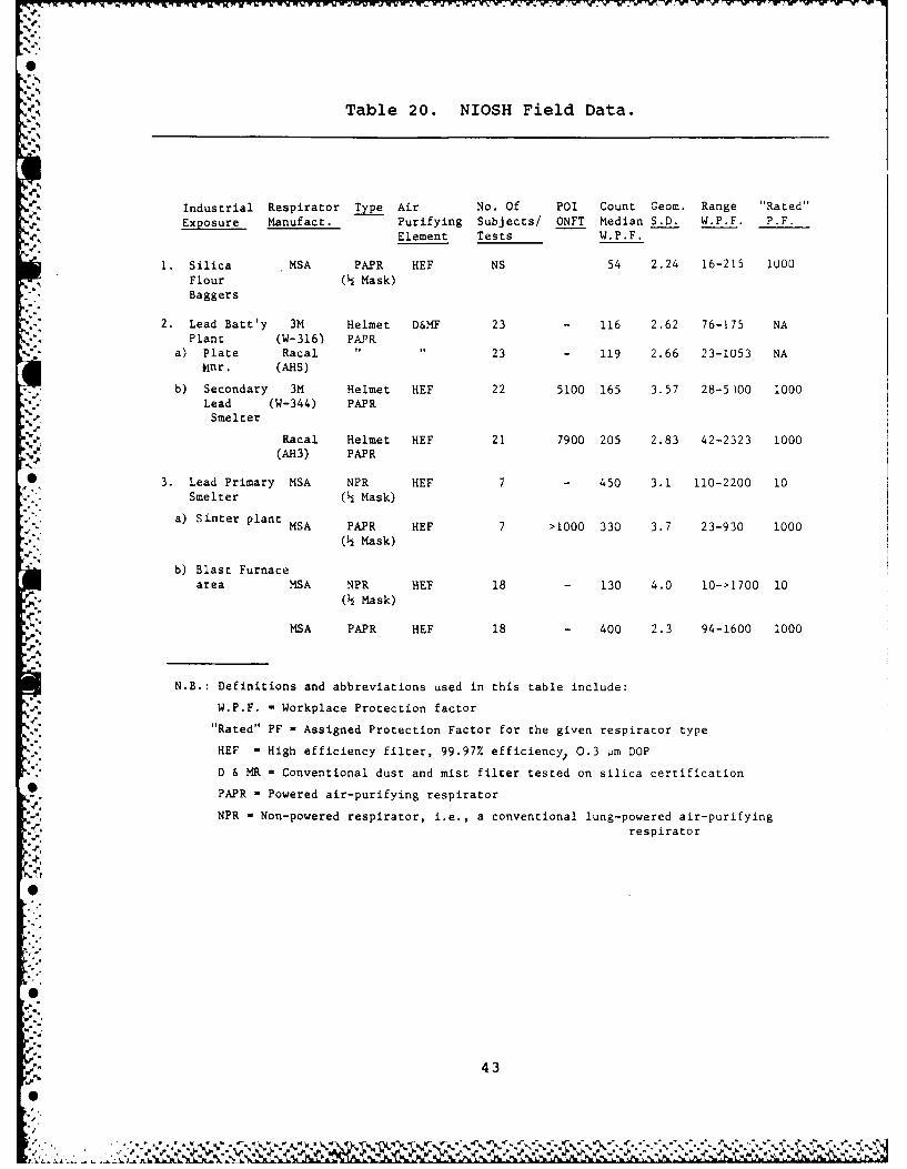
Table 20. NIOSH Field Data.
Industrial Respirator Type Air No. Of POI Count Geom. Range "Rated"
Exposure Manufact. Purifying Subjects/ ONFT Median S.D. W.P.F. P.F.Element Tests W.P.F.
1. Silica MSA PAPR HEF NS 54 2.24 16-215 1000
Flour ( Mask)Baggers
2. Lead Batt'y 3M Helmet D&MF 23 - 116 2.62 76-175 NAPlant (W-316) PAPR
a) Plate Racal " " 23 - 119 2.66 23-1053 NA
Mnr. (AHS)
b) Secondary 3M Helmet HEF 22 5100 165 3.57 28-5)00 1000
Lead (W-344) PAPRSmelter
Racal Helmet HEF 21 7900 205 2.83 42-2323 1000(AH3) PAPR
* 3. Lead Primary MSA NPR HEF 7 - 450 3.1 110-2200 10Smelter ( Mask)
a) Sinter plant MSA PAPR HEF 7 >1000 330 3.7 23-930 1000
( Mask)
b) Blast Furnacearea MSA NPR HEF 18 - 130 4.0 10->1700 10
( Mask)
MSA PAPR HEF 18 - 400 2.3 94-1600 1000
N.B.: Definitions and abbreviations used in this table include:
W.P.F. -Workplace Protection factor
"Rated" PF - Assigned Protection Factor for the given respirator type
HEF = High efficiency filter, 99.97% efficiency, 0.3 pm DOP
D & MR - Conventional dust and mist filter tested on silica certification
PAPR - Powered air-purifying respirator
NPR - Non-powered respirator, i.e., a conventional lung-powered air-purifying
A-, respirator
"'5
_ 43
0

dT
The result of these studies are currently beingprepared for publication.
The general conclusions from this review and frompresentations and discussions at this meeting are: (1) furthereffort should be directed to the development of field testmethods and field performance factors (FPF) and (2) fieldperformance factors determined using a concentration averagingsampler system over extended periods at point of use do not agreewith POI FFs and are nearly always found to be lower than POI FFsand the generic PF for class of device.
6. GAS OR VAPOR TEST
One of the issues that arises when considering thecurrent status of testing to determine respirator POI or POU iswhat test method to use. We have reviewed above a number offindings and observations on solid or liquid aerosol particletest systems and field results on NO2, coal dust, cotton dust,
* abrasives, SO2, spray paint solvents and particles, Cd fume, CO,and Pb fume and dust. It is immediately evident that comparisonsbetween the various lab or POI fit tests do not agree and fieldresults do not agree with lab data. We have expressed theopinion that there is no reason why solid or liquid aerosolparticle tests should agree, and further, no reason why either ofthese should agree with a gas or vapor test because themechanisms and kinetics of removal are different for each of thesubstances, by the leaky respirator components or face maskinterface, and by uptake in the respiratory system. Attempt todemonstrate equivalence between various aerosol fit tests and gasand vapor fit tests have been conducted over the past 20 yr.Apparently there have been no organized efforts to provide anykind of round-robin testing to determine differences in data fromeach test system user. There are no absolute (airborne mg/m 3)calibrations on any test systems.
Table 21 summarizes several of these issues. Table 21Apresents a brief summary of the major historical milestones inthe development or use of various aerosol systems (also seeTable 2 for an historical overview summary of respirator tests).
Table 21B presents a summary of gas and vapor testagents that have been described in technical literature. Theonly method currently available commercially in the U.S. for gasand vapor leakage testing is the National Draeger system
* described in Appendix E. Data on comparative leakage factorswith DOP and gas are presented there. The method is simple,
44% P

Table 21. Test Materials Used for Leakage Tests.
Substance Date Investigator, Remarks
A. Particulate Test Materials
Thermal DOP 1940-45 Developed by US Army and Navy (NRL)for high-efficiency filter testing(0.3 urn).
B.globigii 1954 Guyton, Lense, Decker; BWL Ft.Detrick, 1 pm spores.
Uranine 1959 Silverman, Burgess, Stein, Corn;Harvard SPH, CMD = 0.2 um, ag = 2.4,MMD = 2.4 pm, Cext = 4 mg/m3 2.3%sol'n gen., detect 10-9gm/ml in 10• ml sample.
Thermal DOP 1960 U.S. BOM, monodisperse, LSCMD= 0.3(MDOP) arn, ag < 1.5.
-9
1965 U.S. BOM, Sched. 21B describes useof TDOP & Uranine for certificationtests on filters
NaCl 1962 Hounar, UKAEA Harwell, AERE-R4125,nebulizer.
1965 White, Canadian AERE, salt stick (?).
1969 Burgess, HSPH, CMD = 0.2 um, og = 2,Cext = ?,human subjects on bicycleergometer at 4.5 kg-m/min.
* 1970 Dorman, Porton. Brit. Std 4400-69,2091-69.
1971 Persson, Sweden.
1972 NIOSH adopts BOM schedules for res-0 pirator certification, recodifies,-" drops DOP and uranine tests.
Thermal DOP 1971 LASL (LANL), Hyatt, Mitchell, Bevis,(MDOP) develops 0.3 um test system for NIOSH,
begins human tests, problems with sub-[• ject complaints of odor, irritation.
,45
A' l I.

Table 21. Test Materials Used for Leakage Tests (Continued).
Substance Date Investigator, Remarks
Cold DOP 1971 LASL (LANL), Hyatt et al., develops(PDOP) cold air-nebulized test system with
CMD = 0.6 ag = 2, Cext = 25 mg/m3
in 75 cfm, dynamic range to 10- 4 mg/m 3
Pen. 0.01%.
NaCI 1975 LASL (LANL) for NIOSH, systems now madecomm'l by ATI and Frontier.
B. Gas or Vapor Test Materials
H2S, so2 1955 Hoelscher,Hopkins Chem. Eng. Dept.
Freon 12 1962 Frank Adley US AEC-HW.
1963-64 F-12, 114, MSA for US Army 65-70Rockwell.
1978 Packard, AIHAJ 39:723. Dow Trainingw/mouthpc resp. esc.
1964 Morgan UK AERE-R4484.
1970 Bumines RI 7431 WatsonF-12 See Clark CDE JISRP 1(2)', 77(83) quadrapole mass spec.
SF 1970 (78) LASL LA-7317-PF = NIOSH 78-161.6
1979 Inouye, Japan.
2 1964 Dorman, Porton.
He 1975 (.yr, U.S.,J. Vacuum Sci. Tech 12 419, 1975
Ar 1970 GriffinUKAOH 13:147 Dorman, Portonuses quadrapole mass spec.Also see
I Clark CDE (above).
Parafin oil 1979 Balieu, Denmark, J. Intl. Soc. Resp. Prot.1, 125,1983
n-Pentane 1976 deStergeur, US.
Ethylene 1980 Draeger US, Germany.
1978 PasternaK.
46
%
~~~~' La.** ~ ~

'Table 21. Test Materials Used for Leakage Tests (Continued)-.4
C. Comparative Performance Tests Using Aerosol, Gas orVapor Test Materials
Test Materials Compared Respirator Type Result of Test Reference
1. Cold DOP (1.2 pm) vs. Fume Resp. NaCl Pen. =.006 llyaLt,1973
NaCl (0.6 pm ) DOP Pen. = .004
2. SF vs. DOP vs. NaCl "no clear trend" Lowry, 1977NaCl = SF6 = DOP
3. Cold DOP vs. NaCl Half Face DOP Pen. > NaClPen. Wallendorf, 1980
4. N vs. NaCl MK 7 N2 Pen. NaCIPen. Dorman, 1964
5. F-12 vs. NaCl - F-12 Pen.< 0.2% Houmann, 1964
NaCI Pen < 0.01%
6. Argon vs. NaCl no trend Griffin & Webb,1970
4.
.5 47

inexpensive, and field portable. As indicated in Table 21B,although seven gases and vapors have been used, apart from thecommercial ethylene test system of Draeger only Freons(R) havereceived much acceptance. Freon(R) 12 (dichlorodifluoromethane)or sulfur hexafluoride is currently under consideration as astandard by the ASHRAE for laboratory exhaust hood acceptancetestin. usina a MIRAN(R) -IA infra-red analyzer. The stateddetection limit for F-12 with this instrument is 0.01 ppm. Hoodchallenge concentration is of the order of 100-1000 ppm, so
~ detection is of order 10-4 to 10-5 dynamic range (TLV(RJ is 1000
ppm). Freon(R) uptake by the body during inhalation is easilymeasured by serial analysis of alveolar end-tidal air samples.Thus, separating the problem of uptake (or deposition) oninhalation from cavity-mixing on exhalation (e.g., see Stewart
.. and Petersen's classic study).
8 Table 21C presents a summary of results of comparativ'etests of aerosol-aerosol or of aerosol-gas/vapor for respiratorleakage determinations. Although early studies of DOP and NaCl
0 seemed to indicate little difference, most recent tests indicateDOP pen > NaCl pen, consistent with theoretical expectations.Wallendorf's test results5 at LASL (LANL) in 1978-79 on equalsized Cold DOP (PDOP) and NaCl (MMAD = 0.6 + 0.2 1m = 2.0,Cext = 25 ± 5 mg/m3 for PDOP versus MMAD = 0.66 + 0.i3 m, g =
2.2, Cext = 15 + 2 Mg/M3 for NaCl), are indicated in Table 22.Differences on individuals are not great and are much greaterbetween individuals on a single mask or between masks.
Differences between aerosol (NaCl) and gas (SF6) testresults from LASL (LANL) have been summarized by J. Boardway,
* U.S. Army CSL in a private communication (1983), as shown inTable 23. Lowery of LASL (LANL) stated in 1979 (LA-6722) thatthere was "no clear trend" in human exposure tests. Tests on abreathing machine-headform with demand SCBA indicated that NaCIpenetration = SF6 penetration. Charcoal retention or capacityfor SF6 is poor, it is not held well by charcoal, apparently.
As a general conclusion, one finds that leakagedifferences determined between any two materials in laboratorytests tend to be smaller than inter-subject or inter-respirator
0 differences. No clear trends are apparent. No major theoreticalor experimental fundamental study has yet been found. There areno reasons why leakage should be the same for two differentmaterials.
8 48

Table 22. Half Mask Penetrations for Fit Test with DOP andNaCl4 .
.4.
Test Respirator
,ublect A B C D
DOP NaCI DOP NaCI DOP NaCi DOP NaCI
EZ 0.16 0.11 5 37 2.78 0.75 0.22 2.4 1.47
(0.02- (0.05- (0.10- (0.07- (0.27- (0.17- (1.3- (0.41-0.27) 0.21) 10.6) 7.3) 1.6) 0.30) 3.2) 2.5)
JM 0.05 0.04 0.25 0.09 5.0 0.60 34.6 20.5(0.03- (0.03- (0.15- (0.04- (3.5- (0.47- (30.4- (18.0-0.07) 0.06) 0.31) 0.14) 7.4) 0.71) 41.7) 23.8)
DM 12.3 10.3 22.0 12.2 1.15 0.-10 33.7 15.1
(3.3- (1.7- (11.2- (5.9- (0.58- (0.34- (28.0- (6.5-20.9) 16.3) 30.7) 18.7) 2.2) 0.62) 37.9) 23.2)
JJ 1.51 0. "7 20.9 9.50 0.76 0.35 3.2 2.3
(0.05- (0.05- (11.9- (4.9- (0.57- (0.20- (0.34- (0.42-. 7, o.61) 8 .4) 5 8,,_ _ _ 4.4) 0.40) 29.9) 16.o) 0.3?) 5.8)
NK 16.2 14.? 34.8 21.4 0.74 0.15 1.7 1.4
(4.0- (2.8- (16.6- (11.0- (0.31- (0.10- (0.- - (0.09-28.7) 23.4) 44.8) 28.1) 2.33) 0.21) 2.6) 2.6)
0
49
*.1.. . ....%dm ~ N

Table 23. Vapor/Aerosol Leakage Correlations Parameters.
SF6 vs NaCl and DOP (NIOSH/LASL. 1977)
Results:
Penetration (%)Test NaC1 DOP SF6 Comments
Man Tests n = 50 All indicate < 1 to > 10 Differencesn = 5 between agents> 1% 4.0 4.6 4.6 masked by
variationwithin eachtest (10subjects, 5tests each)
I
HeadformTest x 5.0 4.17 5.1 Six replicatesw/Breather - indicatesPump s 0.37 0.31 0.26 good correla-
tion (1/8" x1" capillaryleak)
CONCLUSIONS:
1. "Since the NaCl and SF6 results (controlled leak bench tests)are in excellent agreement, it was concluded that aerosol and gastest agent leakages should be equal when these agents are used todetermine respirator protection factors."
I
2. "These results show that a respiration PF obtained with anaerosol... is valid when.. .used in a gaseous contaminant. Thismeans... approval criteria need not include both aerosol andgaseous quantitative fit tests..."
5
I
" 50
I
4.

7. CRITERIA AND POTENTIAL METHODS FOR NON-INTRUSIVERESPIRATOR QNFT MEASUREMENT
A presentation of the type of leakage tests that do notrequire penetration of the mask is summarized as follows.Desirable characteristics or criteria for acceptability are shownin outline form in Table 24. If the QNFT is to be used in thefield or away from a laboratory, the system must be portable andconsistent with available electric power. When used as a POU orfor numerous subjects, it must be easy to operate and provide therequisite sensitivity for in mask concentration measurement.
Table 24. Parameters for Non-Intrusive Test Methods.
1. Portability2. Ease of Performance
" 3. Sensitivity
4. Specificity
5. Accuracy6. Precision7. Approximation of Working Conditions8. Engineering Specifications9. Safety
10. Cost11. Integrated vs. Real Time Results12. Interior vs. Exterior of Mask Cavity13. Temporary vs. Permanent Modification
The method of analysis must also be appropriatelyspecific, accurate, and precise. The placement of a measuringelement either within or on the respirator must not interferewith its functional use in working conditions appropriate to theuser. It must be safe to use and not entail excessive cost.
-V.
Most desirable is a sensor that gives real timesimulant (gas or aerosol) concentration information, as does thelight scattering instrument, since it is apparent that the cavityconcentration varies during the respiratory cycle. However, if asuitable simple method (such as a paper tape indicator) can bedeveloped that is an indicator of integrated dose during the testperiod, this would probably be acceptable for field testing.
The issue of whether the sensor should be exterior or* interior to the mask cavity was discussed. An interior sensor
would have to record information or transmit it to the exterior,
51
SJ-

either by telemetry or by hard wiring. Hard wiring again appearsto raise the problem of mask penetration, but if the wiringconnection could be incorporated into the mask molding, thiscould probably be accomplished without loss of integrity.
This question of exterior or interior sensor is also* relevant to the issue of whether the sensor should be permanently
mounted in the respirator or be a temporary insert. If retest isdesired, it may be desirable to have the sensor permanent, if it
"- can be assumed that no degradation of its performance will occurover the respirator lifetime.
Table 25 is a list of the methods presented and4 discussed. These include methods in which the dose of a testsubstance is determined by a biological assay such as urine,blood, or skin test. The analysis, done by collection ofrespiratory exhalate, is also a type of "bio assay", somewhatless invasive than blood sampling. The list is organizedaccording to sample collection, sample analysis, and data
.- recording and transmission.
During the presentation and discussion outlined above,.- numerous comments were offered. These have been organized into
five groups, dealing with: (1) the necessity of non-intrusive
tests (NITs), (2) the definition of "non-intrusive",. (3) suggested parameters for evaluation of NITs, (4) suggested
- .methods, and (5) the means of categorizing these methods.
What was probably the most important discussioncentered around whether or not NITs were really needed at all.Proponents noted that by testing individual masks on individual
* wearers, unencumbered by tubes and able to perform their work- routine, WPFs can more accurately be determined. In addition,
being able to show an individual what happens when he dons his*" particular mask would be a positive training aid and would
enhance motivation to wear the respirator. A reference was alsomade to unknown interactions involved with extracting samplesfrom the mask cavity. On the other hand, those who felt NITsunnecessary argued that the variability in other aspects of QNFTwould swallow any variability between respirators of the samemanufacture.
Throughout the beginning of discussions there appearedto be some vagueness about what "non-intrusive" was intended tomean.
52
0"°
................................ °...........
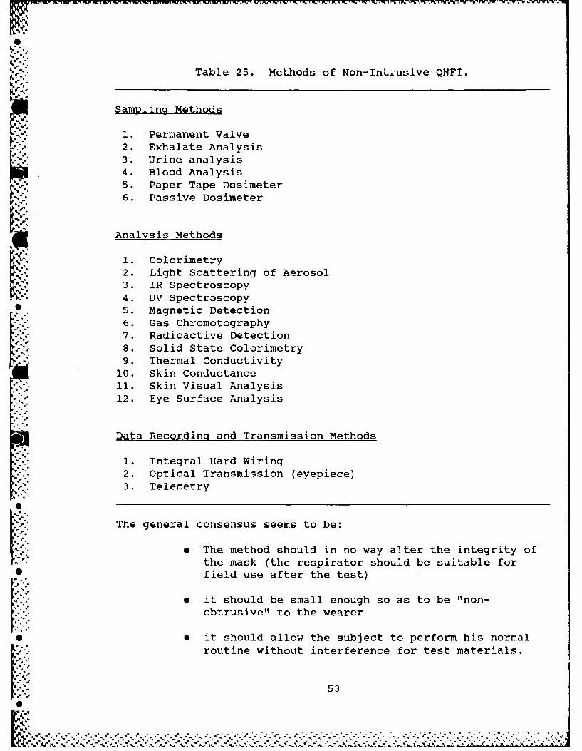
q M PIE S X MW I
Table 25. Methods of Non-InLiusive QNFT.
N! Sampling Methods
1. Permanent Valve2. Exhalate Analysis
3. Urine analysis4. Blood Analysis5. Paper Tape Dosimeter6. Passive Dosimeter
Analysis Methods
1. ColorimetryI: 2. Light Scattering of AerosolI %3. IR Spectroscopy
4. UV Spectroscopy* 5. Magnetic Detection
6. Gas Chromotography7. Radioactive Detection8. Solid State Colorimetry9. Thermal Conductivity
10. Skin Conductance11. Skin Visual Analysis12. Eye Surface Analysis
Data Recording and Transmission Methods
1. Integral Hard Wiring2. Optical Transmission (eyepiece)3. Telemetry
The general consensus seems to be:
e The method should in no way alter the integrity ofthe mask (the respirator should be suitable for• field use after the test)
e it should be small enough so as to be "non-obtrusive" to the wearer
9 * it should allow the subject to perform his normalroutine without interference for test materials.
53.[ ..

From this "Blue Sky" definition, a number of impliedparameters arise in addition to those overtly stated in thediscussion. The system should be totally enclosed within themask cavity with no connections external to the respirator. Someform of telemetry would be important here. This wouldnecessitate a sensitive, miniaturized system that would remain inthe cavity practically unknown to the wearer. It should beeither impervious to or protected from the high temperature andhumidity conditions of the cavity and should give a real timeresponse in order to be able to differentiate where peak dosesoccurred and how inhalation or exhalation affect leakage. Thiswould also indicate an active rather than a passive system.
While these parameters outline an optimal situation inthe future, suggested methods addressed not only that aspect butpresent limitations as well. The first was some sort ofpermanent valve that could be capped when not in use; this raisedobjections to the idea of putting yet another potential leak into
* the mask. Implanted passive personal dosimeters could notdifferentiate between inhalation concentration and those presentduring exhalation. An in-mask filter in the form of a mouth plugwas suggested, but this could hardly be called "non-obtrusive" tothe wearer. Colorimetric paper assays raised the most commonobjective of all: it is not sensitive enough.
Finally the view was offered that the methods should berecategorized into methods of collection (or sampling), methodsof measurement, and methods of recording the data, all three
being incorporated into a single system.
8. WORKSHOP ON IMPROVEMENTS NEEDED ON CURRENT METHODS
The workshop on improvements needed in current methodswas led by H. Ettinger (LANL) with participation by J. Pritchard,
.- J. Agarwal, J. Boardway, and C. Billings (Reporter). The workinggroup first identified current methods of human fit/leakagetesting as aerosols, oil mist (DOP/DOS/Corn Oil); NaCl (nebulizedby Dautrebande, Collision, or thermal salt-stick vapr/condn);B. globigii; and possibly paraffin oil (described in some German
0 articles); and gases/vapors: SF 6 ; Freons(R); and ethylene. After* consideration of the amount of experience in use of these methods
and specific objectives of the proposed applications,* consideration was restricted to DOP, NaCl, and BG.
* The next area of workshop discussion related to needsin the area of apparatus and procedures for its use, includinggeneration, sampling and analysis, calibrations, Q/A,
54
............. ...........-7- '-. 2 .

- dissemination or transport system, type of chamber or hood, andmethods for selecting representative subjects, protocol for testprocedures or test plan, and exercises to be used. These wereconsidered in terms of the purpose of the test and the point orlocation of the testing (e.g., research and development in alaboratory versus field tests for face fit or risk analysis ongroups of wearers, shelf life surveillance, Q/A, etc.).
The area of unknowns or limitations of current practicewas explored next. These included questions of possible toxichazard in interactions with subjects, and interactions of testmaterials with materials of construction of the respirator or of
. . components of the measurement system (e.g., use of a vapor test
on charcoal is likely to be a destructive test requiringreplacement of cartridge). The need for fit factors or fieldperformance factors greater than about 104 was discussed. Theseestimates for agent effects are necessarily limited tosubpathologic although physiologic changes may be used in alimited way with physically fit and trained users (e.g., CS).
* .Non-invasive test apparatus and procedures that would notcompromise device integrity would be desirable, if possible.There was a general agreement that standard methods, apparatus,procedures, protocol, and exercise regimen would benefit fromresearch. Air sample size (1-5 Lpm now) continues to provide anunknown amount of leakage. (The question of sampling only oninhalation with a cavity mounted collector as done by Silvermanand Burgess in 1959 was not discussed.) (The need for real-timeinstantaneous read-out versus a 5-10 min wait for removal andanalysis as with dye aerosol was also not considered). There isa general agreement that particle size analysis needs to beconducted on a continually scheduled basis, with periodicrechecks and instruments for this needed research. Anapproximate particle size has not been selected, except what has
been thought to be needed, but no research has been done on theparticle size of leaks. (Particle size of maximum penetrationwill probably be different in this application than was developedfor space filters with HEF media). The location (geometry,shape, etc.) of sampler inlet within the mask cavity has neverbeen investigated as to its size seiectivity or its ability toextract a representative sample. This bears, of course, upon the
• question of contaminant flow and distribution within the maskcavity and the nature of the effect under consideration, and whatthe target issue for effect is (e.g., the eye versus URT/LRTpulmonary gas exchange, etc.). Sampler design, line length andline losses, and configuration were also judged to be unexplored
*and their effects unquantified to date.
55
'ez e.,.e . ..e
,o°.5

There was a reiteration of the need to explorelaboratory or POI data relationships to actual FPF/WUF/MUC in thefield at POU. The definition of terms need discussion andagreement. Standards for appropriate exercises need to beexplored, developed, and proposed for review and opinion. Thestatistical interpretation of test data is in a deplorable state,and bears directly upon the practical consideration of the costsof protection versus benefits and acceptable risk to thoseoverexposed.
The deliberations of the working group and recommendedresearch items are summarized in Table 26. Needed research isgrouped into three broad categories:
•o I Apparatus and Procedures
e II Test Protocol
e II Date Analysis and InterpretationI
- 9. WORKSHOP ON NEW METHODS
The purpose of this workshop session was to identify,discuss, and prioritize research and development needs related tonew methods for respiratory QNFT. It was recognized at theoutset that the current methods of QNFT are basically laboratorymethods and that the only practical field test methods presentlyused are qualitative in nature. Thus, before new methods couldbe developed for POI or POU (field) tests, ic is necessary toestablish operational requirements for such methods. Only whensuch requirements have been agreed upon by the users can theapproaches which best fit these requirements be developed for thelist of possible methods.
The workshop participants discussed in detail the lackof information on aerosol parameters and their influence on
*, leakage. The aerosols that are currently used for QNFT have beenchosen for convenience; they are for the most part, the sameaerosol systems chosen for filter testing. The size of such
*aerosols was chosen for filter testing to give what was presumed4 to be maximum penetration of the filter. There is no reason to
assume that an aerosol that gives maximum penetration through afibrous filter will give maximum leakage through a respiratorface seal or components.
56
4

Table 26. Improvements to Current Methods.
I. Apparatus and Method for Substance Generation, Delivery
1. Toxicology of Oils2. Characterization of Aerosols (size, charge, etc.)3. Behavior of Monodisperse vs. Polydisperse Aerosol4. High Output Generation5. Standardization of Generation of Aerosol6. Non-Intrusive Test of Current Substances7. Probe Location Effects8. Distribution of Contaminant in Facepiece9. Location of Major Leaks for Facepiece
10. Automated Sampling11. Faster Response Instrument for Concentration Measure12. Linearity of Light Scattering/Flame Photometer
Instruments* 13. Chamber Design: Size, Shape
14. Recording and Computing - A/D Converter
II. Test Protocol
1. Standardized Definition of Protocol2. Arrangement of Exercise3. Standard Anthropometric Criteria4. Improved Training Techniques5. Environmental Effects on Test Results
III. Data Analysis and Interpretation
1. Dose vs. Peak vs. Pass-Fail Criteria2. Reproducibility3. Relationship of POI (PF/FF) to POU (FPF, WUF)4. Small Number Statistics5. Risk Assessment of Data
The participants identified the effect of particle sizeand other particle parameters (e.g., charge, physical state) uponrespirator penetration as a significant gap in knowledge and a
* major need for research. Particularly lacking is any informationon particles smaller than 0.1 pm and particles larger than 5 pm.However, it was agreed that the entire spectrum of sizes ought to
57
. . . . . . . . . '. .

be systematically investigated. It has been tacitly assumed inpast studies that a single aerosol, be it oil or NaCl, couldserve as a suitable surrogate for all aerosols and vapors. Thepracticality of this hypothesis needs to be determined.
In order to accomplish these studies, methods ofmeasuring aerosol size distributions both inside and outside arespirator need to be developed. This raises the further issueof the possible differences in size distribution of the outsideand inside aerosol. It has been assumed that the fraction ofaerosol penetrating the respirator has the same size distributionand thus can be measured in the same manner to obtain aconcentration ratio. If this is not true, then the measurementof concentration, especially if by light scattering, is flawed bythe presence of particles that either under or overestimateconcentration.
The psychological factors that influence respiratorusage have been identified as an important gap in knowledge andan area for needed research. This was emphasized in thepresentation by H. Ettinger on oil aerosol method. Arelationship was derived demonstrating the effect of exposurewithout respiratory protection on the "effective protectionfactor" of an 8-hr exposure period. Even if the "protectionfactor" or respiratory protection is very high, the effectivevalue is markedly degraded if the fraction of time without
* protection becomes appreciable (> 10%).
Needed research in this area includes study of themotivation for long term continuous use of respiratory protectionas well as the short term use of a respirator when an immediateneed for protection is evident.
The use of aerosols as surrogates for vapors is anotherarea perceived by the participants to be of importance as a
* research topic. Two major questions were raised: (1) is anaerosol an appropriate surrogate for vapors with respect to
respirator leakage, and if so, (2) what size and composition of. aerosol gives the best approximation of vapor leakage? Few
studies in the literature or elsewhere have addressed this issueand none have carried out studies where the measurements weremade simultaneously. The widespread use of aerosols as testagents even when vapor exposure is the only hazard makes this animportant and relevant area for study.
Another important area for research is the practicalupper limit of concentration ratio for respiratory protection.
584

-S
Factors > 100,000 have been reported in some studies. Thisrequires that the concentration method of whatever agent usedmust be accurate over a 5 to 6 order of magnitude range.Practically speaking, even if an instrument has the desiredsensitivity, it must be calibrated by a dilution method over thisrange. There is a need to develop accurate dilution methods upto 100,OOOX for aerosols and vapors that can be independentlyverified. Both the oil and NaCl methods of aerosol analysis havenot been accurately calibrated to a concentration for factors> 100,000.
Up to now, studies of respirator fit have identifiedphysical factors appearing to be related to leakage. Thesephysical factors include strap tension, head movement, bodymovement, body position, or acceleration. There is a need formore quantitative and systematic studies of such factors thathave been described only qualitatively in the past. As well astesting the entire respirator in motion, there is a need todetermine the effects of work related motion upon components suchas the valves.
The workshop participants identified all of the aboveproblem areas as important. They are listed in an approximaterank of priority. The first five areas were denoted as "mostimportant" while the remaining areas were denoted "important."
10. WORKSHOP ON FIELD EFFECTIVENESS EVALUATION
The first conclusion of this group was the need todevelop field tests for respirator effectiveness. Field testsare important because they can significantly improve respiratordesign, improve certification procedure by including field tests,permit both POI and POU testing of respirators, and permit betterevaluation of respirator programs.
IThe workshop participants noted the preliminary results
of workplace protection by NIOSH and recognized the rationale for"controlled" field testing by workers closely monitored for maskusage patterns. They recommended that methods be developed totest respirator protection during typical user condition,including training, maintenance, and workplace use. Thesemethods should be used to study large groups of workers, enough
.P1 to assess the effectiveness of respiratory protection programs.
Research needs were discussed and the group agreed thatthe following areas were important:
59
N
* Mask probe design
e Effect of probe location and flow rate
o Interaction of breathing cycle and deposition withsample concentration
0 Effect of body and head movement on leakage
S Effect of work rate and work task on leakage
11. WORKSHOP ON NON-INTRUSIVE TEST METHODS
The workshop discussion began with an attempt todistill a set of objectives out of what had transpired in thegeneral meeting. It was decided that our aim was to listcriteria to be met by any methods and areas of research topursue.
* During the discussions, however, it was realized thatthe technology is not presently available that would allowimmediate implementation of NIT. It seemed, rather that threestages were required: Stage I, where the measuring and recordingsystem could be miniaturized enough to be carried by the subjectbut remain external to the mask; Stage II, that would find thesampling system small enough to be implanted in the mask; andStage III, the entire system would be totally enclosed, and therecording signal would be telemetered out.
The criteria in the workshop would apply to Stage III,although at present we are just beginning to enter Stage T. Asis obvious from the definition of NIT., given in the general
- discussion, the system must be totally enclosed in the mask andable to transmit a signal to some remote station. Thisnecessitates minimal size and weight that will not affect the
[1I* characteristics of the mask. The system must also be immune toVor protected from mask cavity conditions of elevated temperature
and high humidity. It must be fairly sensitive, able to measurelow concentrations of challenge agent, while also being able tomeasure very high concentrations and clear quickly. In order to
* measure peaks of leakage associated with certain movements anddifferentiate between inhalation and exhalation, real time or
. delayed real time must be possible. Since the system would onlybe necessary during testing, and because it probably could notwithstand the vigorous cleaning that the respirator would be
0 subjected to, it should be a temporary unit, easily implanted andremoved. Further, because there would be one unit mask, rapid
60

'.P~~~~~~~~~~ -r V r~ Iw.W~- U~ Wx Y-M xWE %r WA. min WVW EW E- N rU~K~~ l J 'V Pt'U WJ L rWW I1MU*Z -,gE rp VVV*J.'W
IRA
calibration and easy maintenance are required. And finally,there is the ever-present desire for nominal cost.
These criteria almost immediately remove presentmethods from consideration, although in the future presentmethods may be adapted to fit them. Some methods consideredinclude chromatography, measurement of electrostatic charge, andlight-scattering photometry. One problem encountered with thelatter would be interference by water droplets in exhaled breath.(Perhaps this could be dealt with by using some hydrophobiccoating on the sampler).
At this point, Stage III still seems fairly distant.In the meantime, the dynamic environment of the mask cavity needsextensive study, and any size dependence of leakage that existsmust be determined. Further, innovative approaches to fittesting must be examined and bench-top experimentation ofpotential methods must be conducted. Finally, new sources ofaerosols must be explored. In size dependence determination,
* laboratory methods of producing various size ranges must bedeveloped to fill in present gaps. And in field testing, thefeasibility of using naturally occurring aerosols must beanalyzed; if this is found unsuitable, methods of large scaleproduction of aerosols must be designed.
12. WORKSHOP ON GAS AND VAPOR TESTS
The workshop participants reached the consensus that avapor method for respirator fit is necessary particularly for themilitary because the threat of principal concern is a condensablevapor. It is also believed that industry has similar concerns inmany circumstances.
A vapor test method offers certain advantages over- ." aerosol testing. For the military need to measure the equivalent0 of a "workplace protection factor" in the field, a simulant vapor
is probably simpler to generate, control, and measure. The useof nontoxic vapors might also be used as a tracer to trackworkplace leakage in some industrial settings. Both active andpassive systems are conceivable. Detection and Assay systemswith great sensitivity are known. For example, hydrogen flameemission detection is an extremely sensitive method for sensingsulfur or phosphorus bearing vapors. For active systemsminiaturized GC equipment already exists. A passive system mightbe as simple as adsorbent carbon pads inside and outside the
* mask. An extended system might employ time-sequenced exposure ofthe sorbent surface, thus providing a concentration history.
61
S1

Passive systems could be "non-intrusive" by definition. TheNwoLkshop listed the following as R & D needs:
" Acquire a data base on possible tracer materials-toxicity, physical and chemical properties
* Perform feasibility studies on possible
methodologies, equipment and test procedures
* Develop prototype systems
* Perform comparative studies with prototype systemsunder controlled conditions with human subjects
* Develop correlations
- Aerosol vapor- Between systems
e Develop final field-useable systems
o Acquire systems
. Design and conduct field trials
13. SUTMMARY AND CONCLUSIONS
This peer group review meeting of respiratory QNFTmethods was intended to consider:
* Advantages and disadvantages of presently usedfit test methods
* Applicability of present methods to fieldeffectiveness measurements
e Improved methods for determining leakage ofrespirators
* Other research needs to put the field of respiratoryprotection on a firmer scientific footing.
Both instrumentation and methodology were considered inpresentations, discussions, and workshop sessions as important
* components of fit test measurement. An important concept0 enumerated early in the meeting was that fit tests serve several
functions (research, evaluation, certification, POI, etc.) and
N 62

. 11 S T 7 T I qrlv v. Z _W V TXI - W,
that the specific methods must apply to the appropriate need.Thus, new fit test methods and instruments must be designed forfield effectiveness because present methods are only usable inthe laboratory.
The development of fit tests methods from filtertesting methodology involved several assumptions (maximumpenetrating aerosol size) that are unproven for respiratorleakage. There is a need to examine this issue, as well as aneed to improve the dilution and calibration methods for both oiland salt at low aerosol concentrations.
Fundamental studies of leakage as a function ofparticle size are needed, with special attention to ultra-fineparticles (< 0.i m). The use of aerosol as a surrogate forvapor leakage needs to be critically examined and tested bysimultaneous leakage measurements. Studies of the mixing of airwithin the cavity of full-face respirators are needed toelucidate the effect on leakage measurements and the role ofdesign on rebreathing.
Once methods for field effectiveness measurements arevei~ped, -hse should be applied to specific instances to
obtain a data base for comparison of laboratory and fieldmeasurements. Initial studies suggest that present laboratorymeasurements may not be good predictors of field performance.
For POU testing (non-intrusive tests where maskintegrity is maintained), accuracy, inexpensiveness andoperational simplicity need to be developed. Several approachesappear to have potential for such measurements and should be
.. investigated.
Both aerosol and vapor test methods for QNFT should be* developed because there are certain situations where vapor agents
are more desirable than aerosols. Feasibility studies of non-intrusive vapor methods should be supported as a possible fieldmethod. Specific suggestions for needed research are included.
14. RECOMMENDATIONS FOR FUTURE RESEARCH
Recommendations for future research, frequently withjustification for the need, are given throughout this report andparticularly in the sections dedicated to workshop deliberations.A summary of the major recommendations follows:
63

0 With respect to currently used respirator fit testmethods (NaCI, Oil Aerosol)
- Develop dilution and calibration techniquessuitable to 100,000 X and permit independentverification.
- Determine suitability of these or other aerosolsas surrogate for vapors. Correlate aerosol datawith vapor data, preferably simultaneouslyacquired.
Determine effect of particle size and otherparticle parameters (e.g., charge, physicalstate, etc.) upon respirator penetration (include
S. particles > 0.1 pm and > 5 pm).
- Develop method for measuring size distributionEinside and outside a respirator.
-. Complete toxicological data base for oil to beused as test aerosc..
- Develop upgraded instrumentation to include:
- automated sampling- automated data analysis- higher sensitivity detectors (for Fit Factor
105 - 106)
0 With respect to new respirator fit test methods:
* -Conduct research leading to development ofnonintrusive test methods for field test use. Inview of current limitations in the state of theart in applicable technology, consider a phase
* approach.
Pd Stage I: Measuring and recording system, miniaturized
but carried by subject external to mask.
Stage II: Sampling system small enough to be implantedin mask.
Stage III: Entire system enclosed in mask with signal"' telemetered.
0
64NV

0- . - - - - N % - -X
* . Approaches with potential leading toward Stage !TI arelisted in this report. Priority emphasis should be given tolaser light scattering photometry and miniaturizedchromatography.
.4" - Develop a vapor test method especially formilitary field test use. Consider both active(e.g. miniaturized GC) and passive (e.g.adsorbent pads inside mask) approaches.
- Investigate feasibility of using naturallyoccurring aerosols for field testing.
s Additional research needs applicable to all methoas
- Effect or probe design, location and flow rate onleakage data
- Interaction of breathing cycle and deposition withsample concentration
gs\ - Effect of work rate, work task, body and headmovement on leakage
- Define psychological factors that influence
operator usage
, Obtain agreement of the technical community with
respect to:
- Terminology and definitions for respirator fittest and results
- Standardization of fit test apparatus and- procedures
• 65

S
-4
-4
a9
'p
*1* Blank
4.
~.1
S-4
4-
S
4.
S
66.4
.44-
0
- - -. - S - 4 - - - - A .- XX ~

F%
LITERATURE CITED
1. Pritchard, J.A., A Guide to Industrial RespiratoryProtection, HEW Publication No. (NIOSH) 76-179, Supt. Doc.,USGPO, Washington, DC (1976).
2. Myers, W.R., et al., Letter to the Editor, AIHAJ,Vol. 44, p B-26 (1983).
3. Caldwell, R., and Schnell, E., RespiratorEffectiveness in an Enriched Uranium Plant, Presented at the1968 American Industrial Hygiene Conference, St. Louis, MO.
4. Willeke, K., Ayer, H., and Blanchard, J., "NewMethods for Quantitative Respirator Fit Testing with Aerosols,"AIHAJ, Vol. 42, pp 121-125 (1981).
5. Wallendorf, L.J., "A Comparison of Dioctyl Phthalateand Sodium Chloride for Respirator Fit Testing,' M.H.S. Essay,John Hopkins University School of Hygiene and Public Health,
* Baltimore, MD 21205 (1980).
6. Hack. A., et al., "Letter to the Editor," AIHAJ,Vol. 43, p A-16 (1982).
7. Burgess, W.A., "Research Needs in RespiratoryProtection," J. Intl. Soc. Resp. Prot., Vol. i(i), p 27 (1983).
8. Binley, R., Notes from a Seminar on Resp. Prot., JHUSHPH (1982).
9. Samimi, B., et al., "The Efficiency of ProtecitveHoods Used by Sandblasters to Reduce Silica Exposure," AIHAJ, pp140-148 (February 1975).
10. Levine, M.S., "Respirator Use and Protection fromCarbon Monoxide," AIHAJ, Vol. 40, p 832 (1979).
0
67
0•
U . . . . . . . ..- . . --'- ,- .- . . '- -2 ,."' - ° < ' / . - - / " . 2 -; , •i".' ', 2 < -, i' < ' -i .- . ,' < °,- "- '- '-' " ;' ,'.- '. ," °2 ', .- '. .'° .' -. ,' -' '. ...- • -. - ." -.. ".' -. -' '- -i '- ,; '-
-, Blank
68

• .°
APPENDIX A
MEMBERS OF THE PEER REVIEW GROUP
%.o
'C
* , ,."a
0
69
".0 -
,° o.. a'

Blank
* 70

-- K~--.' W~ X''U 'fl 1W U U -M Fw13U" -- 7 - V .1WV) JVTJVVVW-vp IM 1 Xnu- An %T Mgt
Name
John A. Pritchard
". Warren R. Myers
Ching-tsen Bien
John McCreadie
John C. Boardway
Jugal K. Agarwal
Rachel Laird
Frank Rosenthal
* Gilmore J. Sem
Harry J. Ettinger
Bernard V. Gerber
Robert A. DeRoza
Charles J. Shoemaker
Samuel J. Troutman
James J. McCrystal
Klaus Willeke
0.. Richard W., Brletich
Tom Hall
Frank Shanty
David L. Swift
Charles E. Billings
Appendix A 71
0

-'- u.~ w~ u*'~~ U-: - '~U- ~ ~ W -
kS
4.
4.
I.-
p.'.
Blank%,J.
0
4'
'-p
-S
S
72
I,.

.
',
4'.'.
4 "-
4?',7
'.,
.4..

Blank
74

SCIENTIFIC PEER GROUP REVIEW OF RESPIRATOR QUANTITATIVE, FIT TEST METHODS
Time: Thursday and Friday, March 24 and 25, 1983
-i Place: The Johns Hopkins School of Hygiene and Public Health
AGENDA
Day 1
8:30 am - 9:00 am Introduction and Objective C. Billings
of Peer Group Review Meeting;Workshop Assignment
9:00 am - 9:45 am Summary Review of Aerosol D. Swiftand Gas/Vapor Respirator Fit
* Test Methods and Equipment,Criteria for Non-IntrusiveTest Methods
;-
9:45 am - 10:15 am Break
10:15 am - 10:40 am DEHP/DEHS (Corn oil) Liquid H. EttingerAerosol Particle Apparatusand Procedures: Experience,Advantages, Disadvantages,and Areas of AdditionalResearch Needed
10:45 am -11:15 am NaCI Solid Aerosol Particle J. McCreadieApparatus and Procedures:
' Experience, Advantages, Dis-. advantages, and Areas of
Additional Research Needed
11:15 am - 11:40 am Review of Field Tests of W. MyersIn-mask Exposures in
0 Industrial Environments
11:40 am - 12:00 n Gas/Vapor Tests and C. BillingsSuitability of AerosolParticulate Tests as
* Surrogate for Fit forGas/Vapor Exposures
APPENDIX B 75

I ta-
12:00 n - 1:30 pm Lunch
1:30 - 2:30 pm Discussion of Non-Intrusive D. FayTest Apparatus and Proceduresand Potential New Test Apparatusand Procedures, (List, Discuss,Prioritize).
2:30 - 2:45 pm Criteria for Tests vs. C. E. BillingsObjectives vs. Location
2:45 - 3:00 pm Break
3:00 - 5:00 pm Workshops on Needed ResearchRequirements:
A. Improvements to Current Methods,Apparatus and Procedures
B. New Methods for Laboratory or* Point-Of-Issue Fit Tests
C. Design of Methods for FieldEvaluation of RespiratorEffectiveness During Use
D. Non-Intrusive Fit Test ApparatusE. Gas and Vapor Fit Test Apparatus
and Procedures
5:15 - 6:15 pm Wine and Cheese Mixer cn 9th FloorCafeteria
. 8:30 - 10:00 am Workshops on Needed Research (continued)
10:00-10:30 am Break
10:30 - 12:00 n Review and Reports
12:00 n Laboratory Walk Through.(Lunch in cafeteria if you wish)
"0
4.
APPENDIX B 76
V6
4.- .~**44*-* *.1A*

"V Nil
SCIENTIFIC PEER GROUP REVIEW OF
RESPIRATOR QUANTITATIVE FIT TEST METHODS
Workshop Group Assignment Room
A. Current Methods H. Ettinger, Leader 2006
J. PritchardJ. AgarwalT. BoardwayF. Rosenthal, Rep.
B. New Laboratory R. da Roza, Leader 2008Methods J. DeField
S. TroutmanG. SemD. Swift, Rep.K C. Field Evaluation W. Myers, Leader 2010
Effectiveness R. LairdC . Bien
V. BergmanC. Billings, Rep.
D. Non-Intrusive Test K. Willecke, Leader 2033
Methods J. McCreadieW. Burgess
C. Shoemaker
D. Fay, Rep.
E. Gas-Vapor Tests B. Gerber, Leader Board Rm
P. BreysseD. CampbellJ. McCrystalF. Shanty, Rep.
0
APPENDIX B 77
0•

I
'4
'p.
4~,
'p.
I
Blank
/
'4
4%,
.4.
-.4
.4'
-'.4
I
I
S
I
78
I
.-. *~ *****-~*'.4,.. .4 X.' .~4 .4.~ *~4. 4~~4 '~ ~44 .4 44
444 44.44*t..t~M..M.flS.~fltS.t~&.4.S~L..Kfl..flAt R...,..n..w.. 4' - 4'
APPENDIX C
* H. ETTINGER VISUAL AIDS
79
rS

Blan
I
'-.
a"
a,
at0
I
% ". ..-. .• - -. .... .•• . * .- + ., .° + - o o . . + . - , o- - -. .-Blan k - .

OIJ:T
to 4
APPENDIX C 81

00 .5o
C~6 o2 40./srr
.3 2.
AV,~7j C 8

/4
5i,°
* ..
-. 4.
,, ,'.APPENiDIX C. 83
4

014
i. '. .
6low
%4
AxPPENDIX C 84
%"

R.1
4S'4
* : : ~ .i ; i i - i : . i - j . -i
'. - .
2) 1?6 c- 0
-. ."*
-e Ue
W,-'7,APPENDIX C 85
- -0
C'eC' °,.
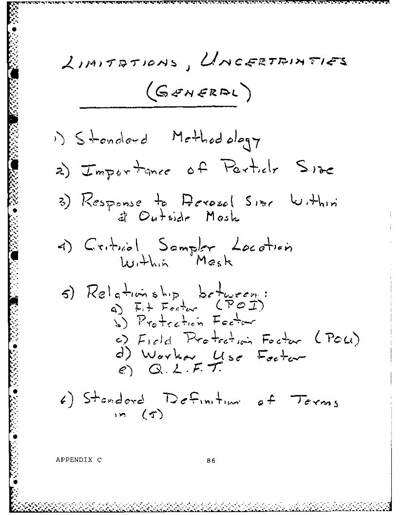
= %
icV
II
,.°- .cZ C_.4.- -K
"or
APPENDIX C 86
,:, -.-.,,,.-. .,,,.. ,- ..,..-.., . .:.::.......,...-................., -,,. ... ,.........--.....-......-.. .,..

*~ ~ ~ ~ ~ ~ ~ ~ ~~~V .w-* zw PUT - - ,-' . -,.- -.. . - L v-7~ - ILNILI Z UR K:9 X Sf' f' -' K. - Nf' L Rf' ~ U' IL' Tr' )C W-P W-7 VER Wlf J .r ~~ M R~ PE 57 1 unuJ
2, o,
(p147c
-j9
IMe
J 40I
00
APPNDX 8
0
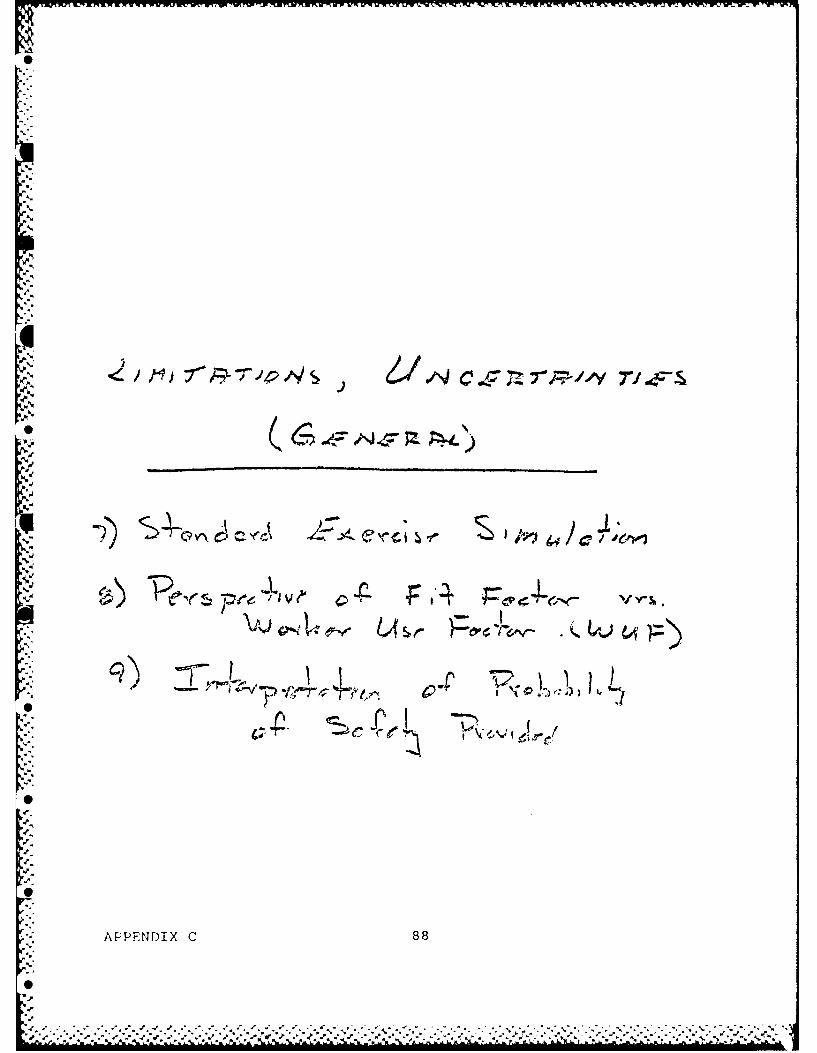
FI mT R. .. .
clcI-N
LE " '
-"C °e
APPENDIX C 88
U,.
-.. - -,r .,-

-TI VIA -e
4t .......
' ,. . . .-. . ... 1
.L4
,.L)I I" "I , 4 . i
L-
/3o
APPENDIX C 89
e e°e' . . . *-- . --.- a

K Blank
- 90

1%~
0* ~
'A.
A.
A.W~. ~C
A.
A.
APPENDIX D
METHOD OF DATA ANALYSIS FOR OIL PARTICLE PENETRATION ESTIMATE
A.
*-~-~1---40I
'1* 10
1 91--p.
* ~ ,.
A.'

0
% .
Blank
0
92
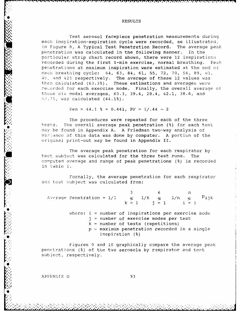
RESULTS
N.%
Test aerosol facepiece penetration measurements duringeach inspiration-expiration cycle were recorded, as illustrated,Ln Figure 8, A Typical Test Penetration Record. The average peakpenetration was calculated in the following manner. In theparticular strip chart record shown, there were 12 inspirationsrecorded during the first 1-min exercise, normal breathing. Peak
Npenetrations at maximum inspiration were estimated at the end ofeach breathing cycle: 64, 63, 84, 61, 55, 72, 70, 56, 89, 61,4k, and 42% respectively. The average of these 12 values wasthen calculated (63.3%). These estimations and averages wererecorded for each exercise mode. Finally, the overall average ofthese six modal averages, 63.3, 39.4, 28.4, 42.1, 38.6, and52.7%, was calculated (44.1%).
Pen = 44.1 % = 0.441, PY= 1/.44 - 2
The procedures were repeated for each of the threetests. The overall average peak penetration (%) for each testmay be found in Appendix A. A Friedman two-way analysis ofvariance of this data was done by computer. A portion of theoriginal print-out may be found in Appendix II.
The average peak penetration for each respirator bytest subject was calculated for the three test runs. Thecomputed average and range of peak penetrations (%) is recordedin Table 1.
Formally, the average penetration for each respiratorand test subject was calculated from:
•3 6 nA'erage Penetration 1/3 1/6 1/n Pijkk 1/ j 1/i : i
where: i = number of inspirations per exercise modej = number of exercise modes per testk = number of tests (repetitions)L'. p = maximum penetration recorded in a single
"" inspiration(%
Figures 9 and 10 graphically compare the average peakpenetrations (%) of the two aerosols by respirator and testsubject, respectively.
APPENDIX D 93
0

.. . .. .. ..
- NOTESTART
IS 2% ±
.el,
I4
6 MO
Figure 8. A Typical Test Penetration Record.
*APPENDIX D 94

.4,
4..-
...
.' -. °
,44.9
44o

S
4%4.
.4
'.4
4A
4~~4.
-4
.4,
0
Blank
4.
4.
.4
.4
-4
S
.4.4
6
*44~
*44
4.
6
-4, 96-4.
.4-
6
S **'~~ . -'

National DraegerCanopy-Type Mask-Fit Tester
PARTS LIST
Collar Seainrg LinrPart Nc, R90030
Collar Fram"e Ass* mh V Complete4 Pwti No R90010
Mul Gas~
4alNo6 26065
N,) P Nt72W),
Nr4 x-~ 1-
Ordering Information:
Specify Draeger No. R9000
* Ficiure 1. Parts List for National Draeger Canopy -Type Mask FitTester.
APPENDIX E 97

5:( MASK-RTTESTER
National Draeger, Inc.101 Technology Drive P Rtsb rgi PA 15275 415767 im
4TELEX866A
Subject:
Canopy-TypeI Unit for
Half-MaskFit TestingThis National Draeger system al-
* lows. quantitative measurements
to be made of mask fit - reliablyand very economically
The testing system is based onusing ethylene gas as a means ofevaluating breathing mask tight-ness - reading the amount of eth-ylene gas in exhaled air with a
It D-aeger Gas Detector Tube
The National Draeger Canopy-Type Test Hood is applied to the subject wearing ahalf mask respirator With ethylene gas admitted to the Test Hood. the subjectbreathes normally A Draeger Ethylene Detector Tube and Multi-Gas Detector Pumpare used to read the amount of ethylene in exhaled breath - providing a quantitativemeasurement of the mask leakage
lut
,ollar n positon with Collar Liner Half-Mask in position with two inhala- Applying Ca.opy ifiu which ethylena seal at the neck of subject tion bags and exhalation chamber lead- is fed - prior to beginnint of fitness
ing to test bag applied in ports in Collar test.
Figure -. C o.,-TYPC TJLJ t f - rali-Mask Fit Testing
APPENDIX E 98
%..

S
V.
~% .:
'p..'
'p.'p.
% ..
'p
~' ...
--'p...- 'p..
Sr
APPENDIX F
0NON-INTRUSIVE TEST METHODS
N
p.
0
Srp..
p.
-p.
0
%.* %-p
,A. *~
0
99
PA
0

II
V. -
'p
-a.
'I
0

PAPER STUDY OF NON-INTRUSIVE QNFT METHODS
1 i. INTRODUCTION AND DEFINlTIONS
Respirator QNFT can be employed for several purposes,as emphasized above in the Peer Review Report. These includeresearch and development of respirators, certification, POI, POU,re-test after use, and re-test after storage. Presently usedmethods, as discussed below, have been designed primarily as acroc _
2._ type of initial POI testing where the wearer determines
what size respirator gives the best fit and tests the donning andadjustment of the respirator to give an "acceptably minimal"degree of leakage.
In such tests, the user is not tested with their own
respirator, but with a standard size respirator that has been
fitted for QNFT. From discussion and data presented at the PeerReview Meeting, it appears that such "laboratory" tests, while
* fulfilling the requirement of finding an "optimal fit" do notassure that the degree of protection measured in such tests willbe realized in the field use of the respirators.
This argument is the rationale for developing newmethods of QNFT that can be used in the field and can be carriedout on the wearer using their own respirator. It is arequirement of such tests that the respirator be fit for use
* after the test. Most existing QNFT methods (except as discussedbelow) first require the respirator cavity be sampled through atube that penetrates the mask somewhere on the facepiece. Wedefine such test methods as 'intrusive' both because they requirepenetration of the mask, thus compromising its integrity, andbecause the sampling intrudes upon the normal movement of airwithin the mask during inspiratory and expiratory movements. Theeffect of sampling air for concentration measurement is notknown, but it may produce an altered pressure distributioncompared to the normal situation without sampling. Conversely, aQNFT method that does not require the integrity of the mask to becompromised and that measures concentration without extractingair from the mask is defined as a non-intrusive QNFT.
It is the purpose of this section to review existingtests that are non-intrusive, to consider criteria that a newnon-intrusive test must meet, to list possible methods that mightbe employed for such tests, and to suggest what methods appear to
* be most feasible and worthy of research investigation anddevelopment.
APPENDIX F 101
Si

,w , -r ... r, . rw. ~~br MW .r r- WV rd WV WJ w, v r -i, - . . r ; W . r r - v -r r r. -rr ] -'r Y ' 'r r nr - -
6I
2. PRESENT NON-INTRUSIVE METHODS
A survey of methods that are being or have been usedfor QNFT indicates that two gas methods and one aerosol method
Acould be classified as non-intrusive. These will be described
briefly below and critically evaluated in general and specifi-
cally for field use.
Argon gas has been used (1) to test the leakage of fullface masks. In this test, the head and upper body are enclosed
by a plastic hood that is cinched about the waist. Pure argongas is injected into this space from an inlet tube atop the headand bathes the region about the respirator. The respirator inletand outlet valves are connected to flexible tubes. Oxygen is fedthrough these tubes to the mask (by a demand regulator) andexpired air is vented to the outside via a sampling bladder.
9From this bladder a sample is taken for gas analysis with a massspectrometer whose sensitivity is stated to be of order 10 ppm.Thus, with pure argon outside the mask, a concentration ratio ofup to 105 is, in principle, possible to measure. The subject was
"- able to do a limited number of simple head movements and walk ona treadmill during the test. However, the subject had to remaintethered to the argon supply and to the sampling bladder duringthe test.
As a laboratory method to test respirator leakage, thismethod exhibits good sensitivity and employs a proven analyticalmethod, mass spectrometry. However, its disadvantages includethe use of inspiratory and expiratory tubes that may limit headmovement and distort the mask fit because of their weight.Sampling exhaled air to estimate mask leakage has been favored bysome investigators. This approach requires that respiratoryuptake be known, that mixing between tidal air and mask space airbe estimated, and that no backmixing occur in the exhalate line.
*For argon, the first factor is known, but the other factors areuncertain, as is the concentration of argon around the maskassumed to be 100%.
As a field method, this method does not seem feasiblesince it requires a gas tank and a mass spectrometer, aninstrument that at present, is not manufactured for use in thefield. It also does not permit body or head movement that wouldsimulate the job activity of respirator users.
A somewhat similar gas method is the ethylene leakage* test that was developed by National Draeger and is described in
detail in Appendix E of the Report. It differs from the argon
* APPENDIX F 102I

- test in that breathing tubes are not used and the exhaled airconcentration is sampled by a color indicating tube.
In this method, the bag covering the head hasappropriately placed holes to fit over the inhalation cartridgesso the subject can breathe air without tube connections while theremainder of the mask and head arp bathed in air containing 2%ethylene. An exhalation line leading to a sampling bladderleaves the bag through a tight fitting hole.
A ctct-r tube for ethvlene has a detection limit ofapproximately 1 ppm; thus a leakage factor (PF) up to 2 x 10⁴ canbe measured with an accuracy of approximately 25% (that of thedetector tube). A source of 2% ethylene (a calibrated tank) mustbe available to conduct this leakage test, making the methoddifficult to perform in a field situation. Similar questionsregarding the free movement of head and body (as with argon test)apply to the ethylene test. Ethylene is not significantlyremoved in the respiratory tract, but the relationship of maskconcentration to exhaled air concentration is not known in
[° general.
The only aerosol method that could be considered non-intrusive is the method employing airborne bacillus subtilis orbacillus globigii. In this method, a water suspension of thebacterial organisms is nebulized into a chamber and monitored bya light scattering photometer to maintain a reportedconcentration of about 300,000 organisms/L air. The subjectwearing the respirator remains in the chamber for a specifiedperiod; any airborne organisms entering the mask cavity andreaching the mouth are collected on a cotton plug filter held in
- . the mouth in a brass fitting. The number of organisms deposited
on the cotton filter is determined by standard microbiologicalcolony counting following incubation. The particles are reportedto have an aerodynamic mass median diameter (MMD) of about1.0 m. Because it is possible to detect a single organism, this
. method theoretically allows one to measure protection factors inexcess of 106 for an exposure period of several minutes.
Despite this high protection factor detectability, themethod has not been widely used for leakage measurement.
e Although the organism is not pathological, it does represent somerisk if individuals of unusual susceptibility come into contactwith the live organism. Furthermore, it requires some care toculture and maintain the organisms in a state where they can beconveniently used for aerosolization. For these reasons it does
APPENDIX F 103
,""-

not appear that the E.G. method would satisfy the criteria ofdose and portability for a fieldable non-intrusive method.
IA review of existing gas and aerosol non-intrusivemethods suggests that none are suited for field leakagemeasurements that can give the desired sensitivity, portability,and ease of operation. This conclusion suggests that new methodsof non-intrusive leakage measurements should be developed. Froma number of possible methods that might be used, severalpromising methods should be chosen and extensive research and
* development performed. Of first importance in narrowing the- field of methods is the establishment of criteria for a field use* non-intrusive QNFT.
3. CRITERIA FOR NON-INTRUSIVE QNFT
Ten primary criteria were chosen for field use non-intrusive QNFT. It is believed that if a method best meets thesecriteria, it will be the most ideal way to test leakage for arespirator. These criteria are listed in Table I with a shortcomment or explanation.
Table I. Criteria for Non-Intrusive QNFT.i1. Portability - can be easily carried to a field location
*2. Ease of Performance - not requiring a technically trainedoperator
3. Sensitivity - able to measure leakage factors > 100.000
. 4. Specificity - not interfered with by other contaminants
5. Accuracy - gives a "True" measure of leakage
6. Precision - reproducibility greater than intra-subjectvariability
7. Non-intruding - permits normal working conditions or desiredmovements
8. Mass Producible - can meet engineering specifications formanufacturing
APPENDIX F 104
'I..
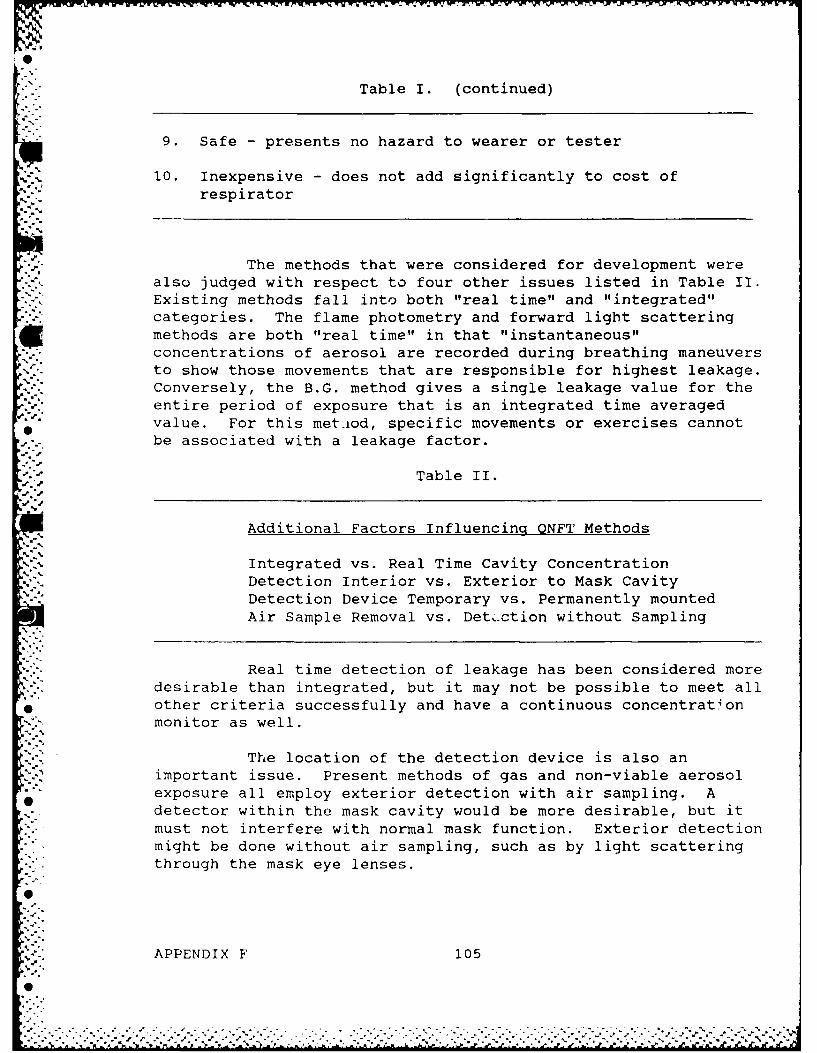
Table I. (continued)
9. Safe - presents no hazard to wearer or tester
10. Inexpensive - does not add significantly to cost ofrespirator
The methods that were considered for development werealso judged with respect to four other issues listed in Table II.
.-b Existing methods fall into both "real time" and "integrated"categories. The flame photometry and forward light scatteringmethods are both "real time" in that "instantaneous"concentrations of aerosol are recorded during breathing maneuversto show those movements that are responsible for highest leakage.Conversely, the B.G. method gives a single leakage value for theentire period of exposure that is an integrated time averagedvalue. For this met.iod, specific movements or exercises cannotbe associated with a leakage factor.
Table II.
Additional Factors Influencing QNFT Methods
Integrated vs. Real Time Cavity ConcentrationDetection Interior vs. Exterior to Mask CavityDetection Device Temporary vs. Permanently mounted
Air Sample Removal vs. Detection without Sampling
Real time detection of leakage has been considered moredesirable than integrated, but it may not be possible to meet all
* other criteria successfully and have a continuous concentrationmonitor as well.
*" . The location of the detection device is also animportant issue. Present methods of gas and non-viable aerosol
* "exposure all employ exterior detection with air sampling. A. detector within the mask cavity would be more desirable, but it*'.-must not interfere with normal mask function. Exterior detection
might be done without air sampling, such as by light scattering" through the mask eye lenses.
APPENDIX F 1050.<
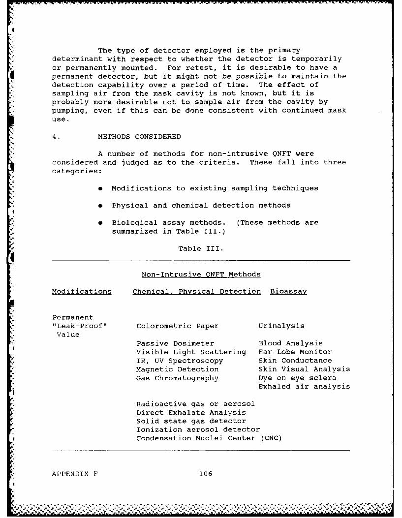
The type of detector employed is the primarydeterminant with respect to whether the detector is temporarily
*or permanently mounted. For retest, it is desirable to have apermanent detector, but it might not be possible to maintain the
*' detection capability over a period of time. The effect ofsampling air from the mask cavity is not known, but it isprobably more desirable iot to sample air from the cavity bypumping, even if this can be done consistent with continued maskuse.
4. METHODS CONSIDERED
A number of methods for non-intrusive QNFT wereconsidered and judged as to the criteria. These fall into threecategories:
e Modifications to existing sampling techniques
e Physical and chemical detection methods4
* Biological assay methods. (These methods aresummarized in Table III.)
9Table III.
Non-Intrusive ONFT Methods
Modifications Chemical, Physical Detection Bioassay
* Permanent- "Leak-Proof" Colorometric Paper Urinalysis-. Value
Passive Dosimeter Blood AnalysisVisible Light Scattering Ear Lobe MonitorIR, UV Spectroscopy Skin ConductanceMagnetic Detection Skin Visual AnalysisGas Chromatography Dye on eye sclera
Exhaled air analysis
Radioactive gas or aerosolDirect Exhalate AnalysisSolid state gas detectorIonization aerosol detector
* Condensation Nuclei Center (CNC)
* APPENDIX F 106

Consideration was first given to the bioassay methodstaken as a whole. While these are attraci-ve because they permitmeasurement of actual "dose", they are generally invasive to adegree that makes the procedures difficult to administer on alarge scale. Therefore, the conclusion was reached that these
methods were not feasible. The permanent valve option is thesimplest approach because it permits existing detection methodssuch as flame photometry and light scattering to be used.
hHowever, it is not truly "non-intrusive" in that it cannot be
assured that the valve will be "leakproof." While this approachcould be taken, it is our opinion that it is not the bestapproach and should be considered a back-up if other approachesdo not give desired results in development.
* Among the category of chemical or physical detectionmethods, several approaches do not appear at present to have
promise of success in meeting all criteria. Magnetic detectiondoes not have required sensitivity, while radioactive gas oraerosol is unacceptable from a subject exposure viewpoint. The
* first two methods are simple but do not offer real time analysis.If this criterion is not necessary they should be developed.While CNC detection is sensitive, it is not non-intrusive,
Orequiring a sample to be drawn from the cavity. The mostattractive methods appear to be solid state gas detection,ionization aerosol detection, and gas chromotography. Devicesemploying these principles of detection and analysis have beenproposed and would fit comfortably within the mask cavity.
However, at present such devices are not commercially available
that have the desired degree of sensitivity and selectivity. It
appears that further development to perfect such detectiondevices will be required to achieve a field effective non-intrusive QNFT.
5. CONCLUSIONS.p"
a There is a need for development of a non-intrusive,field effective QNFT method that can achieve
leakage measurement equivalent to fit factors
> 100,000.
e No present methods of QNFT are capable ofmodification to meet the criteria for a fieldeffective non-intrusive QNFT.
e Of the possible methods considered, taking intoaccount developed criteria, methods that have most
APPENDIX F 107
0.

4M. K X K M _J1 -:
promise are aerosol ionization detection, solidstate gas detection, and gas chromatography, allb inm capable of miniaturization to fit within amask cavity.
e Applied research and development is needed in orderto achieve the goal of a fieldable non-intrusiveQNFT and should be undertaken in the above areas.
*APPENDIX F 108
4
A * *

0"
'p
'p"
"'C...C- ,'-
C- ,
'-,''C-.
'-
%'p-
'0
DEEOMETAD:SEBY FVPO/EOSLTSI. .'

q
I
'II
I
I
I
I
U-
Blank.4
0
'U.
II,
A
I
J
I
110
I
A,.

DEVELOPMENT AND EXPERIMENTAL ASSEMBLY OF A SYSTEM FORSIMULTANEOUS VAPOR/AEROSOL LEAKAGE MEASUREMENT
IN A FULL FACE RESPIRATOR
1 . INTRODUCTION
Although several leakage tests employ gases or vaporsas test agents, the commonly used QNFT methods employ either NaCl
N or oil aerosol. The standard U.S. Army mask is intended forprotection against both aerosol and vapor agents, employing a
" filter and a treated charcoal bed. If these elements are equallyefficient in removing agents in the inspired air, leakage intothe mask cavity is likely to occur primarily around the faceseal.Since vapor agents, such as Savin (GB), are a major concern inthe employment of masks, it is important to know if protectionagainst aerosol is predictive of protection against vapor.Simply stated if a fit factor is measured using aerosol QNFT, thesame degree of protection can be assumed for vapor.
Several studies have been carried out where respiratorleakage was measured first with an aerosol and then with a vaporsurrogate agent. In all cases, the measurements were donesequentially, and it is possible that changes in leakage occurredbetween measurements. In order to avoid this difficulty, weproposed to develop a fit test system that made simultaneousaerosol and vapor leakage factors and tested the hypothesis thatfacepiece leakage of test aerosols is equivalent to vapor leakageof a nerve agent surrogate.
2. CHOICE OF AGENT-AEROSOL
Of the two common aerosol substances, NaCl and oil, it-"- was necessary first to choose a specific aerosol agent for the
test system. There are several oil agents that have beenemployed including DOP (properly di-2-ethyl-hexyl phthalateDEHP), DEHS (Sebacate), corn oil, and PEG (polyethylene glycol).If oil is to be used rather than NaCl, a specific oil must bechosen.
* The primary advantages of oil over NaCl are the non-hygroscopic nature of oil droplets, the ease of generation by airnebulization, and its constant output characteristics. Anotheradvantage is the light scattering method for oil aerosolconcentration measurement; it is less likely to suffer vapor
* interferences than the NaCl flame photometry technique.
APPENDIX G i11
0% %

Several studies have shown that the particle size ofoil aerosol produced from a Laskin nebulizer is similar for DEHP,DEHS, PEG, and corn oil. Because of this similarity and theexperience in our laboratory with DEHS, we chose this oil as theaerosol agent. Furthermore, an Inhalation Toxicology Study hasbeen carried out with DEHS on Fisher rats and the study failed toshow significant lung or systemic effects at exposure levels upto 250 mg/m 3 for exposure periods up to 13 wks. Likewise, DEHSaerosol exposures of a selected number of human subjects fordeposition measurements have not demonstrated acute or chronichealth effects.
3. CHOICE OF AGENT - VAPOR
The purpose of this phase was to select a surrogatethat is a suitable substitute for a vapor organophosphatechemical warfare agent. Of such agents, the substance chosen tosimulate was sarin (GB). The first task was to decide upon the
* physical parameters that should be the basis for a choice ofsurrogate. It was decided, based on factors affecting leakagethrough a facepiece seal, to seek substitutes that had similar
vapor pressure and water solubility. Additionally, thesubstitute must have low toxicity, be detectable by a wellestablished analytical method, and not be excessively expensiveto purchase. Table 1 is a list of 30 compounds that wereoriginally selected for consideration. After careful screening,all but two were rejected on one or another basis; the remainingcompounds were isobutyric acid and dimethyl methyl phosphonate (asurrogate for organophosphate agents used by the U.S. Army fordecontamination and adsorption breakthrough studies). Isobutyricacid was rejected because of its odorant property. Table 2 is acomparison of di-methyl methyl phosphonate (DMMP) and GB. Eventhough the vapor pressure at room temperature is less than thatfor GB, DMMP has sufficient volatility to achieve an airborne
• concentration in excess of 600 ppm, and has high water solubilitysimilar to GB. DMMP is readily available in relatively pure formand can be generated easily by bubbling dry air through the bulk
C liquid. It is sufficiently non-toxic to be used for QNFT for aperiod of several minutes.
APPENDIX G 112
S.V%
9k -l

Table 1. Compounds Considered as Simulants for GB and Reasonsfor Rejection.
Compound Vapor Toxicity Solubility Detectability Availability Otherrressure
Trimethyl phosphate X
Triethyl phosphate X
Tribromomethane X
l-Bromo-2-butanol X
2-Hexanol X X
Trans-futnarylVchloride x
Z-methyl propionylbromide X
1,3-dibromo-2-methyl-propane X
Esobutyric Acid A
*Ethyl glycolate X
2-chloropyridine X
Amyl alcohol X
2-chlorophenol X
Di-(2-methoxy-ethyl) ether X
Enanthaldehyde X
2,2, 4-Trimethyl-3pentanone X
1,2, 4-Trimethyl-benzene X
Isoamyl isobutyrate X
Isobutyl benzene X
0%Dipentene X
d-Limonene x
-. Myrcene X
Cineol X.11-Decene X
% Sulfur hexa-fluoride B
Freons (all) x
TF A - unpleasant odor
B - not excluded by mask or cartridge
APPENDIX G 113
0%
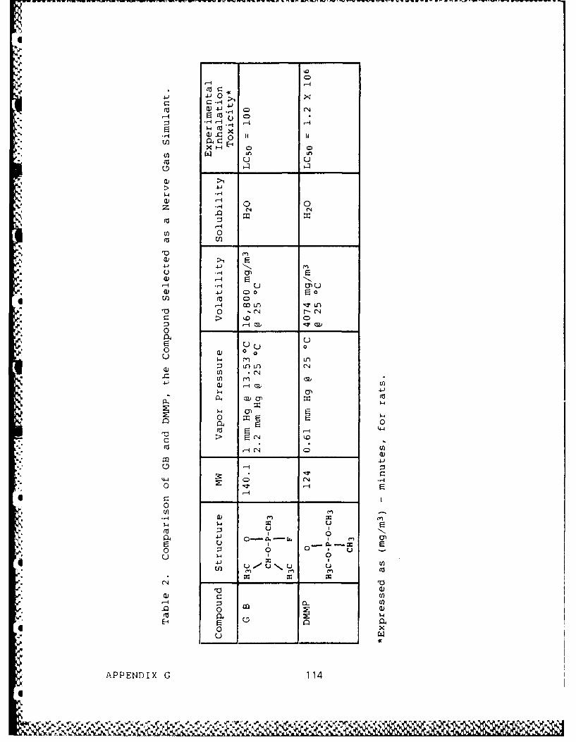
11 0
E-4
>1
W4.1 0 (N
0C~
u 4* -
r-U uUa)41 C 0 0
Al m CD
00 ___
*> CD
0H 1
04 uEl U U0 0
C.) '-O C4
C))
-0 $-4~
S04 0(
> C
U-
0C
Lo Ml
'Iu = 4 0 ~ *J
4-1 1~
* 0 E-40
u w I( 4 -
APPENDX G 11
% % c "AL p

4. EXPERIMENTAL SETUP
Having chosen the aerosol and vapor agents, weproceeded to assemble elements of a leak test system formeasurement of aerosol and vapor mask penetration. Theseelements consisted of agent generation apparatus, an exposurechamber, sampling system for aerosol and vapor, and analyzers tomeasure agent concentration in the box and within the maskcavity.
Aerosol generation was accomplished with a Laskinnozzle nebulizer, commercially produced by Air Techniques,Baltimore, MD (Model TDA-4A). This produces a polydisperse DEHSaerosol having a MMD of 0.9 )m and output mass concentration of4 mg/L. Using one nozzle for generation, we measured a flow rateof 15 L/min from the generator. This flow waT diluted withfiltered room air up to 50 L/min to feed to the exposure box.Calculated chamber concentration is approximately 1000 mg/m
3
(1 mg/L).
-. Initially, the DMMP vapor was generated by Ultrasonicnebulization of liquid from a DeVilbiss Model 35 UltrasonicNebulizer. However, this device uses a plastic cup to containthe liquid, and this was found to be unacceptable because ofchemical interaction with DMMP. It was decided that generationshould be carried out in a glass apparatus. For this purpose weemployed a simple gas bubbler containing 100 mL of liquid DMMPwith a fritted glass bubbler beneath the liquid to assureadequate air-liquid contact.
The DMMP vapor, at a concentration of 100 ppm(500 mg/m 3 ) was conducted to the chamber by a heated flexibleplastic hose of 1-in. diameter at a flow rate of 50 L/min. Thevapor and aerosol lines entered the chamber at the top throughseparate ports located about 3 in. apart.
The chamber was a modified shower stall, purchased fromAir Techniques, Model TDA-70. It is large enough for a singlesubject to stand upright and carry out simple head and armmovements. Aerosol and vapor, with diluting air totaling 100L/min, entered the top of the chamber and was mixed by a small
5 propeller fan in the upper corner. Air left the chamber througha bottom drain and was pumped to the exhaust by a smallcentrifugal blower. Pressure inside the chamber was maintainedat about 0.1" H20 negative.
APPENDIX G 115
0 -

The sampling ports for chamber and mask concentrationwere located about waist high at the side of the chamber. Thechamber sample port extends 1 to 2 in. into the chamber while themask port had a cone fitting for a 1-mm diameter Tygon tubingextending from mask facepiece to port. Slack was left to permithead movement.
Aerosol analysis was carried out with a forward lightscattering photometer. This device contained an optical chamberobtained from Dynatech Frontier (Albuquerque, NM) that included alight source and photomultiplier. Electronics and gas handlingin the photometer were constructed according to a design kindlysupplied to us by Alan Hack of Los Alamos National Laboratory.
DMMP analysis was performed in a CSI Meloy Model 260HYFED Phosphorus Analyzer. This instrument is stated to have asensitivity of 0.0001 ppm phosphorus. In the original design ofthe system, the chamber sample was split into two streams. Onestream was for the DEHS measurement in the photometer and the
* other stream was for DMMP measurement. Because of saturation*problems in the HYFED at 100 ppm DMMP, we intended to run the
sample through a dilution system to reduce its concentration by a* factor of 625; however, this system itself was difficult to
operate without saturation occurring in the rotameters and weconcluded that this system should not be used in the final
* configuration. It is intended, presently, to measure only themask concentration with the HYFED and measure the chamberconcentration by infrared transmission (MIRAN Gas Analyzer).Figures 1-4 are diagrams of the flow configurations of aerosoland vapor generation, sampling, and analysis in the originalconfiguration.
5. CALIBRATION
The photometer was calibrated with DEHS aerosol* contained in a 100-L chamber whose original mass concentration
was determined gravimetrically by sampling onto a membranefilter. Dilution of the aerosol was carried out in stages byremoving 90% of the air in the chamber and replacing the filtered
V air. From this procedure, we obtained a series of calibration* points shown in Figure 5.
The HYFED analyzer was calibrated using a DMMPpermeation tube flow at CRDEC (Edgewood, MD). The calibrationcurve for this instrument is shown in Figures 6 and 7.
APPENDIX G 116
. . . . .

CL)X 0
U 0 0E- - -
qtr 00 C.
4IJ
0
p0
W4
E-- W
F:5 0)n0 ?
APPENDX G 11

VAPOR/AEROSOL IN
100 LPM 'MANIELC
MIXINGFAN
MASKSAMPLING PORT ,a.
'-a,
.. BLOWERTOEXHAUST
.- ,..Figure 2. Test Chamber.
APSAMPLIN PORT8
-p.,

ZERO MASK CHAMBERSAMPLE \SAMPLE SAMPLE
-, ~HEP'TFFILTER
VA0 LYE
0Fiue3 lwDaga o ih-cttrn htmtr
APEDX 1
EXA S

;~ <
-pa. E-
bl.el
p.-
-)v
Ci
0r -
Fiue4 25 iuio ytm
APPENDX G 12

102
* 100%
10
10%
11
01%
I ~10-2 .1
10-
C) 10-2-
%.1

'.5' 102
%' , 1000%
10%
%
z, 101
,IIq
"Q 10-
" '
"""" 0.01%
?..
10
.10-4-
... "0.2 0.3 0.4 0.3'
0.7 1 2 3 4 5 6 74 1 0 20 30O 40 50 100
• "'.Figure 5. Forward Light-Scattering Photometer Calibration, .. Curves.
-. APPENDIX G 121
.

10-' 9
5PA260 BL0024VOLTAGE. -5713OVEN TEMP: 20
BLOCK TEMP: 1552 HFLOW RATE: 45
AN FOW RTE: 58FLAME OFF CURRENT: 1.40 X 10⁻¹²
10-5FLAME ON CURRENT: 2.10 x 10-89CALIBRATOR: DS
7
4
4 2
10L9
7
4
3
10-7 1
2
10-
7
3
2
10-9f tI A79 $5 4 3 2 1va
1 . 0
INRAI7HPHRU PM
Fiue66MPClbain
APPENDX G 12

01
7
3
2
10-6
101 9 9
1. . . 1. 0
INRAI4HPHRU PM
Fiue7 MPClbain
APPENDX G 12

N
. 6. INITIAL TEST RESULTS.
Because of difficulties in establishing a dilutionsystem for DMMP and instrument component failures of the HYFED,it was not possible to carry out actual leakage measurements withthe vapor agent. The completion of this phase of the system isthe first priority of continuing work.
We did carry out a series of experiments on threesubjects with the DEHS aerosol measuring mask leakage on twoairrerent days. The results ot these studies are shown inFigures 8, 9, and 10. The system for aerosol concentrationworked very satisfactorily; we were able to detect withinbreaths, changes in leakage easily from one head movement orbreathing style to another.
We also carried out a study to test interference of
DMMP in the photometer measurement of DEHS. To simulate theworst condition, we generated 100 ppm DMMP and introduced it tothe photometer at the most sensitive level, producing a signal of
4- about 20%. Based on the expected leakage of the agents, webelive this represents a negligible degree of interference.
N°
We conclude that this system is capable of making thekind of simultaneous leakage measurements that we have proposed.We plan to carry out these measurements as soon as the programcan be reactivated.
0
4,.
APPENDIX G 124
.. -.. . - . .-.
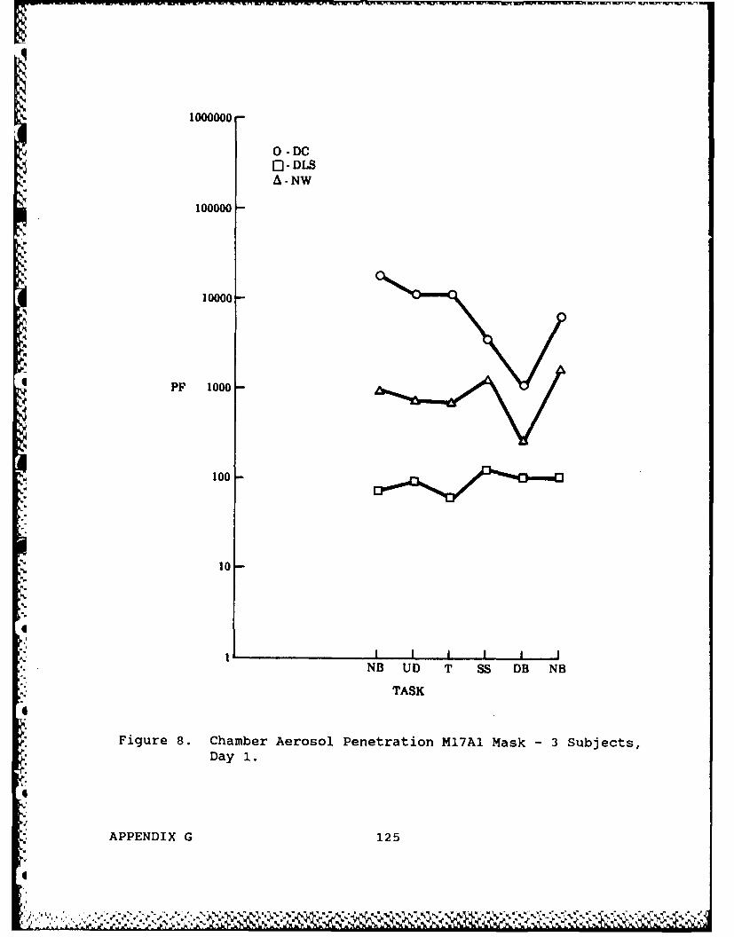
1000000
0 - DC] -DLS
1 A- NW
100000
PF 1000
I
100
10
Uo.
A . I I I I I INB UD T SS DB NB
TASK
4
Figure 8. Chamber Aerosol Penetration M17A1 Mask - 3 Subjects,Day 1.
4
, APPENDIX G 125
4

1000000
000,0
10000
PF 1000
100 -
10-
I % I I I I i I
NB UD T SS DB NB
"" TASK
Figure 9. Chamber Aerosol Leakage-MlTAl Mask Same Subject,
Different Days.
APPENDIX G 126'S %
a..

1000000
0 -DCC]- DLSA -NW
100000
10000
* PP 1000
100-
* 10 -
-TAS
0
--N4
.%4%
0cZ

p.. Blank
128

S
'B
N,"B
B.,
B-,
B,."B."B
-B.APPENDIX H
B-NEEDED RESEARCH
%t.
B."
B..'p
"B.
B."'-B..
S
S
'p..
B,
0.4
J.
129
0
B,

I
Wa.
.q~.
a..
A
A BlankI
g-p
N
*45
a,
a,
a..-a
I
N
a-
a..
IN
I
130
I

-Jr - . Ir W -, l -".-rw -"W.; . ; C - W -' I '
QNFT - NEEDED RESEARCH AND SPECIFIC RECOMMENDATIONS
1. INTRODUCTION
One of the major purposes of the Peer Review Meetingheld at Johns Hopkins in March 1983 was to identify gaps in thedata base of QNFT methodology and mask leakage and suggest neededresearch. Many suggestions were made and these are centered inthe report of that meeting. The section that follows draws onthis information, but contains our own assessment of the researchpriorities and approaches that ought to be taken in advancing4 respiratory protection science and engineering.
2. GAPS IN THE DATA BASE.
A review of literature concerning mask leakageindicates considerable engineering effort over a period of 100 yrbut a notable lack of scientific foundation. Up to the present,the requirements for respirator performance have not been welldefined, but with improved techniques and more research workersbecoming interested in the use of respirators, the lack of basicinformation hampers developments that could greatly improve theperformance of these devices. We shall first consider knowledgegaps in mask leakage and their needs for QNFT methodology.
*i A primary issue that requires study is leakage rate ofparticles, vapors, or gases and its relationship to agentchemical and physical properties. For gases and vapors, thisincludes molecular weight, diffusion properties, watersolubility, chemical reactivity, surface adsorption, and surfaceinteraction with other substances. For aerosols, this includesparticle size, particle concentration, electric charge, chemicalreactivity, and hygroscopicity. Studies of leakage performed to
*date have employed simple agents. The effect of these otherparameters on leakage needs to be known if leakage testing is tobe a reliable predictor of actual performance.
Another significant gap in data is the issue of gas and
*aerosol mixing within the mask cavity. This factor has manyimplications in terms of the fate of materials entering the maskcavity at different locations. Very little is known about howthe shape and size of the mask cavity and the location offilters, valve, and oronasal cup influence the pattern ofinspiratory and expiratory flow. No scientific studies have been
I. carried out to investigate the nature of flow and mixing within a
APPENDIX H 131Iw

%respirator cavity. However, such studies are needed to predict%exposure to leaked substance and to aid in future design.
The specific location of leaks and effects of movementon such leaks are another area for the development of researchtechniques. At present, all leakage methods measure overallleaks and no QNFT methods can be used to identify the specificlocation and associated degree of leakage. Such techniques ofquantitative leak location need to be developed so that designchanges intended to improve seal can be critically tested andmajor sites of leakage identified.
With emphasis on high level of protection againstagents, it is important to reexamine the operation of valves,particularly with respect to their operation under fieldconditions and with rapid head movement. The criteria ofpositive seal and low pressure drop, that has guided valve designin the past, needs to be looked at critically to see if newdesigns are needed.
In the area of specific QNFT methodology, perhaps themost important need is the development of methods that wouldenable mask leakage to be measured at issue and in field use.
* Studies carried out by investigators report differences betweenlaboratory leakage and field leakage values. This questions thefundamcntal assumption that a properly conducted QNFT is a validpredictor of field operation. The reasons for the differencesare not known and research is needed to elucidate why such
*' differences are observed and if these observations are true for4'i military respirators.
The need for field measurements of mask leakage is astrong motivation for the development of non-intrusive fittesting methods. This has been discussed in detail inAppendix F. No reliable method of this type exists at present
• and research is required to provide for such a technique.
ZThe effect of sampling from the mask cavity for*i concentration measurement is not known; nor is the effect of flow
rate on leakage. If techniques are developed not requiringsampling, it would be useful to compare measurement with the twomethods. The effect of lung removal of particles or vapors isalso an important issue th, o has received little past atzention.
*[' It has been stated that NaC. aerosols are 80% removed while oilaerosols are probably only 20% deposited in the respiratorytract. A study to evaluate the influence of this factor would
* aid in the choice of QNFT methods.
*APPENDIX H 132

As the need to measure higher degrees of protection isrealized, it is important to determine the calibration of bothNaCl and oil aerosol at very low concentration, using an"absolute" method that does not make assumptions about dilutionor linearity of instrument responses. Present methods ofdilution are unreliable about 1000 X and need to be checked withmethods independent of the above assumptions and sources oferror.
3. SPECIFIC RECOMMENDATIONS FOR RESEARCH
Studies to investigate the effect of particle size andelectric charge on aerosol leakage need to be undertaken. This
4should be done initially on a mannequin or other system that canbe carefully "microleaked" to a specific degree. With data fromthese studies, further studies on a small number of humansubjects should be performed to confirm the findings 'in vivo'.These studies require 2+ yr to obtain adequate information.
Studies of leakage of gases with markedly differentsolubility and adsorption properties should be performed.Comparative measurements should be carried out. Particularattention should be given to skin absorption in human studies.Similar effort to the aerosol studies are required.
Techniques to measure air movement within the maskcavity must be developed and applied to studies of air mixing.Visualization using smoke, or dye in liquid flow analogs may beemployed. Effects of the oronasal cup need to be known in viewof the observation that rebreathed CO2 is higner with suchconfigurations. This is a 2-yr effort to obtain some informationto assist in new cavity and flow design.
A study should be carried out to develop methods oflocalizing leaks during testing. Several ideas have beenproposed for this study including local aerosol delivery anddividing the facepiece seal into sectors by plastic filmboundaries. Six months are needed to develop techniques and 1 yris needed to study the locale of leaks.
IThe field performance of respirators should be studied.
This task requires significant planning to develop a method sothat comparison between laboratory and field can be made. Thisis a large effort, but critical to the assurance of proper fieldperformance. It should require at least a 2-yr effort.
APPENDIX H 133
.. • . ,...,

"I
Calibrations of QNFT methods at low agent concentrationshould be made. This is important if confidence in high values
of protection factor are required. This effort is achievable in
1 yr or less.
The dynamics of valve operation should be studied to* assist in future valve design. Accelerations that are associated
with movement and rapid breathing should be included as a tactor.This effort requires about 1 to 1 1/2 yr.
A
I%
,I
I
S.-
APEDX 3
I.4
SL"2. V*..
L"~C ~

h
APPENDIX I
LABORATORY INSTRUMENTATION FOR AEROSOL RESEARCH
135
-. 2

- -. wr mrnnV
I
Blan
4,,!
.
..
I
*4. . . . 4p 4..

AEROSOL SCIENCE AND TECHNOLOGY LABORATORY RESOURCE REQUIREMENTS
1. INTRODUCTION
This sect-n outlines principal instrument and resourcerequirements for a modern aerosol laboratory for respiratorresearch and development. Types of research to be performedinclude studies on behavior of particles (motion) as controlledby fluid motion and interactions with other particles or gases,boundaries, and obstacles in the flow (e.g., filter fibers).
* Principal parameters under investigation include particleconcentration (mass, number, or area per unit volume ofsuspending gas); particle sizes; material composition andchemical species; and the size-spectral distribution of these andother properties (e.g., electrostatic charge) or characteristics(e.g., deposition and accumulation).
The systems to be developed for aerosol research may bedivided into areas of:
o Generation
o Sampling
o Analysis
o Flow Systems and Chambers
* Personnel Requirements
* Facility and Support Requirements
2. GENERATION
2.1 Purpose.
The purpose of aerosol generations systems is toprovide a continuous and reproducible suspension of aerosolparticles with defined physical and chemical composition,
characteristics, and properties. Principal generator performancecharacteristics include particle size or range of sizes produced,type of materials, and concentration range attainable.Generators are divided into 3 broad categories based on
*properties produced: monodisperse, polydisperse, or simulant.
* APPENDIX I 137
-1 -'.-.-. . *-.. . . . -. .-. %. - * -...

2.2 Monodisperse Aerosol Generators.
Typical devices: (L = liquid particle; S = solid ordried residue).
'- . L LaMer-Sinclair (Vaporization-condensation)(Thermal DOP) Generator.
- Commercial Sources: not commercially available- Approx. Cost: easily built with standard
apparatus ($10,000 est.)
e L Rappaport-Weinstock (Devir) (V-C) Generator
4l - Commercial Sources: TSI- Approx. Cost:
* L, S Spinning Disc (Walton & Prewett/Porton)Generator
- Commercial Sources: BGI, TSI
- Approx. Cost:
, L, S Vibrating Orifice:
- Commercial Sources: TSI
- Approx. Cost:
o L or S Nebulizers with monodisperse PS latexsuspensions
- Commercial sources: DeVilbiss, pneumatic orultrasonic and several others, Dautrebande,Collison
- Approx. Cost: ultrasonic ($1,000 est.); pneum.• (< 100)
2.3 Polydisperse Aerosol Generators.
* Typical Devices: (L liquid particle; S = solid ordried residue).
e L or S Nebulizers for liquid particles or dry
residues
* S Powder Feeder plus Air Jet Ejector Redispersion
APPENDIX I 138
Y0%
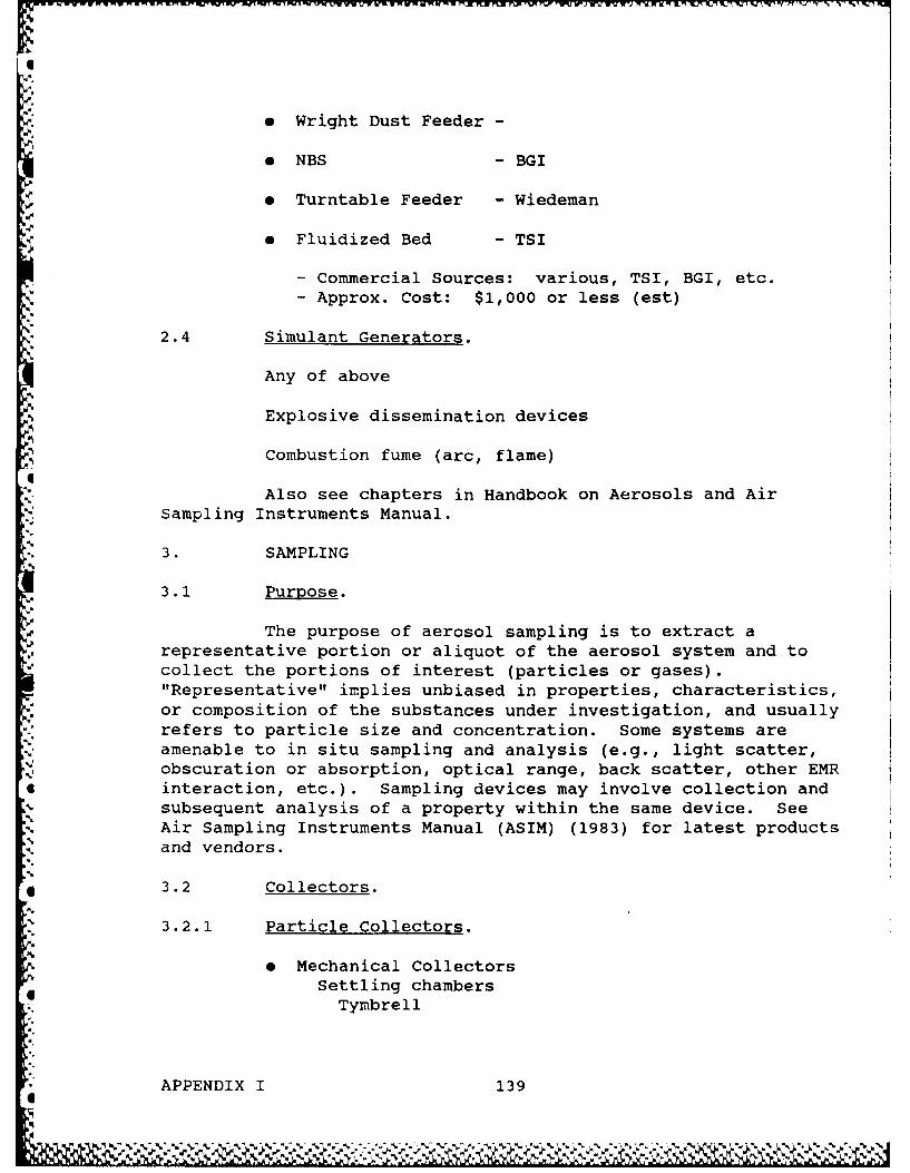
LI-Aa
9 Wright Dust Feeder -
e NBS - BGI
e Turntable Feeder - Wiedeman-A
¢ •Fluidized Bed - TSI
- Commercial Sources: various, TSI, BGI, etc.
- Approx. Cost: $1,000 or less (est)
2.4 Simulant Generators.
Any of above
Explosive dissemination devices
Combustion fume (arc, flame)
Also see chapters in Handbook on Aerosols and AirSampling Instruments Manual.
3. SAMPLING
3.1 Purpose.
The purpose of aerosol sampling is to extract arepresentative portion or aliquot of the aerosol system and to
collect the portions of interest (particles or gases)."Representative" implies unbiased in properties, characteristics,or composition of the substances under investigation, and usuallyrefers to particle size and concentration. Some systems areamenable to in situ sampling and analysis (e.g., light scatter,obscuration or absorption, optical range, back scatter, other EMR
4 interaction, etc.). Sampling devices may involve collection andsubsequent analysis of a property within the same device. See
AAir Sampling Instruments Manual (ASIM) (1983) for latest productsand vendors.
4 3.2 Collectors.
3.2.1 Particle Collectors.
e Mechanical CollectorsSettling chambers
Tymbrel 1
APPENDIX I 139I

HexhletCotton Dust Elutriator
Commercial Source: CassellaApprox. Cost: (< $100)Cyclones
10 mm NylonSA, 1-3 in diam. steel, etc.
Commercial Sources: several (ASIM)- Approx. Cost low (< $100)
Series and parallel arrangements, e.g. cascadecyclones
Sources: Flow Gen.Approx. Cost $1,000 (est.)
ImpingersStandard Greenburg SmithMidgetSources: Several (ASIM)
Approx. cost low (< $100)Impactors(See Table 1 (ASIM)]
* Commercial Sources: See tableApprox. Cost: $1,000 (est.)
Diffusion BatteriesRect. or round channels
" Scrubbers
* Electrostatic Precipitators
Single cyl: wire in tubeCommercial Source, MSA, Del ElectronicsApprox. Cost $1,000 (est.)
Parallel Plate (ASIM)Commercial Source: TSIApprox. Cost $1,000
* * Filters
Several types; fibrous, membrane, pore, granularcost low
* All above devices require sampling pumps and flowmeters, etc.,see ASIM for typical and vendors,
6
APPENDIX I 140
If
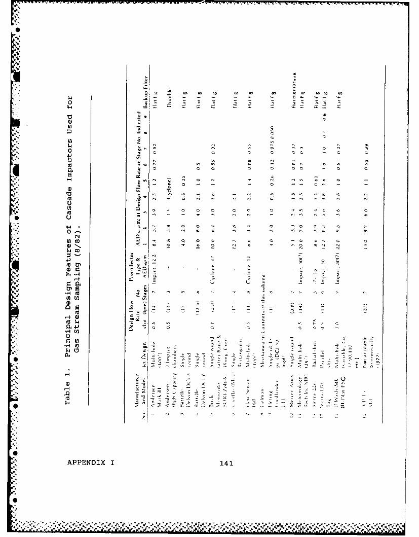
0 x 'X--Xi-'_ rJ ."V. r.n r rw- _rw. -'- .,.. -,.- -.-.-
4)
4 u I - _ _
'5z - . - .
0 .°
4J
114, :: 0 cA
,V.r .5- - - a
4.) C
o .CO
4J -
,9:- M
U., s-sa- o - : .- _- ' _ . C
* 0' -._ , . -C - ' .'A _ C . ' C
P4 -2 CS
" g a . - - . -
0. - -- -. -
c 0
:"APPENDIX 1 141
4.) %r -

3.2.2 Gas and Vapor Collectors.
" Absorption (Scrubbers) (i.e., water, TEA, etc.)e.g., impingers (see above)
- Bead columns, helixes, plate, packed, etc.- Several sources, low cost.
" Adsorption
- Charcoal, silica gel, zeolites, etc.- Several sources, low cost
" Combustion
- Direct flame, catalytic
- Several sources, low to medium cost.
* " Chemisorption
- Specific for gas (e.g., CaO for C02 )
* Condensation
- For condensible vapors (e.g., water)
All above devices require sampling pumps, flowmeters, and mayrequire other utilities, reagents, or condensibles.
3.3 Aerosol Analyzers (May Sample and/or Analyze).
0 Light Scatter Photometers and Size Analyzers
- Royco - several models, approx. cost, $10,000* - HIAC
- Others
*Laser Light Scatter
* - Spectrex
- PM Systems Inc.- Active Cavity (Laser) Aerosol Spectrometer- Approx. Cost ($16,000)- (Knollenberg)
APPENDIX I 142.

I
" Electrical Aerosol Analyzer
- Commercial Source, TSI, several modelsApprox. Cost, > $10,000
e Vibrating Quartz Crystal Microbalance CascadeImpactor
- Commercial Source: QCM, Berkley Controls- Aprox. Cost
. Aerosol Centrifuges (also possible with QuartzCrystal Sensor) Stoeber Spiral Duct (Sorvall)Centrifuge
" Beta Gage Mass Monitors
- Commercial Sources GCA Technology Div.I q- Approx. Cost: $10,000 or less
See Table 2, attached (ASIM).
4. ANALYSIS
4.1 Purpose.
Analysis of an aerosol system may be directed tomeasurements of particle size, number, area, total mass,composition, morphology, charge, and other characteristics orproperties (e.g., shape, density, etc.). Broadly, one is
*[ concerned with measurement of physical or chemical parametersrelated to effects produced by the individual particles or to thetotal cloud and its motion, deposition, etc.
4.2 Physical Analysis.
Physical analysis generally involves measurement ofparticle size spectra and the quantity of material in eachcomponent of the size distribution. Other properties of interest
4include shape, density, and surface phenomena. Instrumentationfor physical analysis include standard laboratory apparatus suchas SEM/TEM/ microscopy, charges, or voltage, etc.
4.3 Chemical Analysis.
Chemical composition is usually determined byconventional analytical laboratory instruments such as atomic
APPENDIX I 143

Table 2. Direct Reading Instruments for Analyzing AirborneParticles.
!ntro~uction . . .. . . .. .. U-2
O ptical .. . . . . . . . . . . . . .... . . . . . . . . . U -3
Pe ~lectr i c . . . .. . . . . . . . . ............... ..... ..... ............. .. .. . ......... I.................. ... . ...... U-5
Beta A ttenuation .. . . . . . . . . . . . . . . . . . . . . . . .. . . . . . . . . . . . . . U -5
instrument DescriptionsVisible Emission M onitor (Lear Siegler. Inc,) .. . . . . . . . . . . . . . . . . . . . . .I. . . . . . . U-6Opacrty Monitors RM7A and RM7N (Lear Siegler, Inc.)............. ....... .................................. .. U-7Remote Opacity Monitor (GCA Corp ) . . . . . . . . . . . . . . . . . . . . . . . . . . . . . . . . . U-8
i act(k Opacity M onitor (Dynatron. inc. .. . . . . . . . . . . . . . . . . . . . . . . . . . . . . . . . ..I. U-8TDA-2E Particulate Detection Apparatus (Air Techniques. Inc.) ... ............ ..... U-8
Light Scattering Photometer (Frontier Enterprises, Inc.)........... ... .............................................. U-9Sigrist Photometer(Greai Likes Instruments, Inc.) .................... .............. ............................. U.9Leitz Tyndcallometer T.M. Digital (Ernst Leitz GmbH) .............................. I............ ..... I......U-t0
MRI Integrating Nephelometer (Meteorology Research, Inc.)........... .. ................. ........... U-IlSinclair-Phoenix Aerosol Photometer (Phoenix Precision Instrument Co.) . ...... .U-12Sartorius Aerosol Photometer (Sartorus Membranfilter GmbH) . ...... ............ U-13Digital Dust Indicator (M DA Scientific, Inc.) . . . . . . . . . ... . . . . . . . . . . . . . . ..r . .. .. U-13Climet Particle Analysis System (Climet Instrument Co. I.............. ........ .... U-14
Forward Scattering Spectometer Probe (Particle Measuring Systems. Inc ... ............. ... U-14Active Scattering (Particle Measuring Systems, Inc.) ................ .... .............. U1HIAC Royco Particle Counters (HIAC. Royco Instruments) ........ U-IS
*. Stationary Single Particle Photometer (Science Spectrum. Inc. ............. U- 16Airborne Particle Counters (Met One, Inc.) .U1..........I..6Condensation Nuclei Counter (BGI. Inc ) .. .. ... . . ... .. . . . . .U- 16
.. 0 Condensation Nuclei Monitors (Environment One Corp.) ..... ............. ... U-17SmallIParticle Detector. Type CN (Gardner Associates, Inc.) ........... UI1SGE Condensation Nuclei Counters (General Electric Co .............. ....I1Condensation Nucleus Counter (TSI, Inc.) . . .. .. .. .. .. .. . .I..I..I................... _9Sartorius Scintillation Particle Counter (Sartorius Membranfilter GrmoH) .... ............ U-20nectrical Aerosol Size Analyzer (TSI. Inc .. . . . . ..). . . . . . . . . . . . . . . U-20
R3irbeDust Mass Monitors fGCA. Technology Div.).... ......... . U-21RAlIRea, Time Aerosol Monitor IGCA Corp.) .... U-22
',-1e FAM 1, Fibrous Aerosol Motilatr (GCA Corp. U-23S's..Portable Dust Monitor (Rotl~proe & Mitchel., Ltd .U-23
>.'-Inuous Aerosol Monitor, Model PCAM ippm., Inc ... ..... :.. .- 23Respirable Aerosol Photometer (TSI, inc.1 LJ-24Respirable Aerosol Mass Monitor ITSI. Inc.) . ........ ...... U-24Aerod,,namic Particle Sizer )TSI, Inc i ....... U-25
*'QCN C_-"! ascade Impactor (Ber~cev Controls, Inc ).. ...... ............. . . . . . . .. . . . . . . ... U-25.ion Daughter Analyzer (H.s-,haw Chiemical Co )- .--i. .. U-25
Ir'ant W~orking Level Meter %IDA Scientific, Inc.) ...... U-26ntveAerosol Air Monitors 'Eberline Instrument Corp ... .... U-26
P A;r Part:cuate Monitor,, Nuclear Measurements Corp is
APEDX 4
0%
% Z. Z

absorption, gas-chromatography, XRF, etc. from collected samplesof the aerosol particulate material. Services of such alaboratory are required.
5. FLOW SYSTEMS AND CHAMBERS
Aerosol research will require one or more suitablechambers for the generation of static clouds of particles for usein calibration, test, or exposure. Typical chambers may range insize from 20-40 L, up to several hundred or a thousand cubicmeters (e.g., room size). Larger chambers are equipped withaccess locks, viewing windows, instrument access ports, lines,etc. Small to medium chambers are typically glass (carboys) or
44 glass-lined tanks. For dissemination research, high-pressure
designs may be necessary.
Flow systems have advantages and may be used forcertain types of aerosol research. Aerosol tunnels areessentially wind tunnels with a defined flow field in the test
* section, plus the addition (upstream) of suitable particlegeneration and administration apparatus. Tunnel sizes may be1 in and up to several ft in diameter at the test section.Both chambers and tunnels represent a long-term capital equipmentinvestment.
6. PERSONNEL REQUIREMENTS
A senior aerosol scientist/engineer is required foroverall planning and management of test programs. Qualificationsinclude education (Ph.D), experience (10-20 yr productiveresearch), and national stature (e.g., of the stature of HenryGreen of Porton). An administrative staff is required to overseeprocurements, budgets, library, and facilities. Specific
'- technical staff will include aerosol/environmental engineers,physicists, chemists, and depending upon the nature of work,
* aerosol toxicologists.4")
7. FACILITY AND SUPPORT REQUIREMENTS
Other resources include experimental mechanical shop* with modeling and molding capabilities, an electronics shop, a
library, suitable research modules, and offices adjacent. Accessto main frame computer facilities and mini-computers to processdata on-site are essential.
APPENDIX I 145