1
-1853 2 -1854 2 L Sheet Metal Mounting Plates, Brackets Dimension Configurable Type Part Number MMaterial SSurface Treatment Type Material Symbol FALZS FALAS FAPAS FALCS FADAS FALDS FADBS FACAS FAMDS FALBS FAEAS FASBS FAMBS FAMAS FANAS FAMCS FATBS SP SPCC E - SPB Black Oxide SPU Trivalent Chromate (Clear) SPK Trivalent Chromate (Black) AM A5052 - AMW Anodize (Clear) AMB Anodize (Black) SUD SUS304(2B) - E 4.5, 6.0 thickness type is SPHC material. EAs opposed to the "Center Symmetrical Type" on the previous page, general tolerance is the guaranteed value for external dimensions. Part Number - T - A - B - L - X - F - H - G - Hole Specification1 Code, Nominal Value - D - J - Y - V - S - W - Hole Specification2 Code, Nominal Value - K Type - Material Symbol FALAS - SPB - T1.6 - A30 - B30 - L30 - X15 - H20 - N5 - Y15 - S15 - NA6 FAMBS - AM - T1.5 - A80 - B60 - L60 - X50 - F0 - H70 - N4 - Y15 - V30 - S20 - W20 - NA5 E There may be some hanger holes on anodized FALZS.(See Specifications and Machining Limits) FALZS FALAS FALCS FALDS FACAS FALBS FASBS FAMAS FAMCS FAPAS FADAS FADBS FAMDS FAEAS FAMBS FANAS FATBS E Slotted hole direction can be changed (See alterations). E Slotted hole direction can be changed (See alterations). E Slotted hole direction can be changed (See alterations). E Slotted hole direction can be changed (See alterations). E Slotted hole direction can be changed (See alterations). E Slotted hole direction can be changed (See alterations). S Y X H L Hole specification2 NA MA A B Hole specification1 +0.2 0 N M DA Hole specification2 NA X H S K Y Hole specification1 N M DA +0.2 0 X H J Hole specification2 NA S K Y Hole specification1 N 2 - Hole specification2 NA MA S V Y A B X H S V Y 2 - Hole specification2 NA MA Hole specification1 N M DA L +0.2 0 V Y X K S H 2 - Hole specification2 NA Hole specification1 N M DA +0.2 0 2 - Hole specification2 NA MA S V Y F H X 2 - Hole specification1 N M V Y K S 2 - Hole specification2 NA F H X 2 - Hole specification1 N M A B F H G X 2 - Hole specification1 N M 2 - Hole specification2 NA MA S V Y L H G X 2 - Hole specification1 N M 2 - Hole specification2 NA MA S V Y V Y K S 2 - Hole specification2 NA H G X 2 - Hole specification1 N M V Y K S 2 - Hole specification2 NA F J H X 2 - Hole specification1 N B A X H Hole specification1 N M 4 - Hole specification2 NA MA V W S Y DA L +0.2 0 2 - Hole specification1 4 - Hole specification2 N M NA MA F H V W S X Y F H G X 4 - Hole specification2 NA MA V W S Y 4 - Hole specification1 N M H G F X D S V Y 4 - Hole specification1 N M 2 - Hole specification2 NA MA +0.2 0 L 4-C2 or less T A B r (Common Dimension) eGreen colored parameters can be omitted. If the parameter setting is omitted, the holes will be evenly distributed about the center. For details, see d P.1834. b b b b f g b g f 5 Ø3 5 QSpecifications, Machining Limits E1. Burr height 0.1 or less E2. Bend angle tolerance ±1° E3. There will be scratches and bulges by Press Brake. For details and bend radius information, D P.1832. E 4. Slotted holes may be shaped as shown below depending on dimensions. (No negative effects on mounting functionality) E6. There are machining limits on b, f, and g shown in below diagram. For details, d P.1834. E5. Anodized FALZS There are hanger holes above T4. QHole Type Selection Chart Hole Type Bolt Hole Tapped Holes (Coarse Thread) Through Hole Code N, NA M, MA D, DA Shape Diagram de M MA D DA +0.2 0 E For d dimension, see "N, NA Machining Dimensions" on lower section of specification chart. Part Number Selection 1mm Increment XFHG Hole Specification1 D JYVSW Hole Specification2 K Type Material Symbol T A B L Code Designation Code Designation FALZS FALAS FAPAS FALCS FADAS FALDS FADBS FACAS FAMDS FALBS FAEAS FASBS FAMBS FAMAS FANAS FAMCS FATBS SP SPB SPU SPK AM AMW AMB SUD SPCC (SPHC) 1.6 2.3 3.2 4.5 6.0 A5052 1.5 2.0 3.0 4.0 5.0 SUS304 1.0 1.5 2.0 3.0 4.0 5.0 20 ~ 200 E For T6.0 ~300 15 ~ 200 E For T6.0 20~ 10 ~ 200 E For T6.0 20~ 0.1mm Increment N (Bolt Hole)E 0, 3, 4, 5, 6, 8, 10 (Select) 3~30 (0.5 Inc.) 0.1mm Increment EJ≤Nx5 NA (Bolt Hole)E 0, 3, 4, 5 6, 8, 10 (Select) 0.1mm Increment EK≤NAx5 M (Tapped Holes) 0, 3, 4, 5, 6, 8, 10 (Select) MA (Tapped Holes) 0, 3, 4, 5 6, 8, 10 (Select) DA (Through Hole) 3~30 (0.5mm Increment) EHoles may deform if the hole locations are too close to the ends and bends, but they will be machined as specified if they are within the machining limits. EN, NA machining dimensions N, NA specified Value 0 3 4 5 6 8 10 Through Hole Dia. (d) (No Hole) 3.5 4.5 5.5 6.5 9 11 Alterations Slotted Hole Angle Change FALCS, FALDS FASBS, FAMCSFADBS, FAMDS Code RC Spec. Slotted holes are changed as shown above. ENote the dimensions relationship Add RC at the end of the type designation (Ex.)~-RC S B Y V Y S B Ordering Code Part Number - T - A - B - L - X - F - H - G - Hole Specification1 Code, Nominal Value - D - J - Y - V - S -W- Hole Specification2 Code, Nominal Value - K - (RC) Type - Material Symbol FALCS - SP - T1.6 - A30 - B30 - L30 - X15 - H20 - N5 - Y15 - S15 - NA3 - K2 - RC A L T Body Price Unit Price Surface Treatment Charge (Body Price+) FALZS FALAS FACAS FALBS FALCS FAMAS FAPAS FASBS FADAS FALDS FAEAS FAMBS FAMCS FADBS FATBS FANAS FAMDS SPCC A5052 SPCC SPHC A5052 SUS304 SPCC SPHC A5052 SUS304 SPCC SPHC A5052 SUS304 SPCC SPHC A5052 SUS304 SPCC SPHC A5052 SUS304 Black Oxide Trivalent Chromate (Clear, Black) Anodize (Clear) Anodize (Black) SP AM SUD SP AM SUD SP AM SUD SP AM SUD SP AM SUD SPB SPU SPK AMW AMB 20~100 10~100 1.0~1.6 2.0~3.2 4.0~6.0 101~200 1.0~1.6 2.0~3.2 4.0~6.0 101~200 10~100 1.0~1.6 2.0~3.2 4.0~6.0 101~200 1.0~1.6 2.0~3.2 4.0~6.0 201~300 10~100 6.0 - - - - - - - - - - - - 101~200 6.0 - - - - - - - - - - - - Price Calculations Add surface treatment charges to the body prices.(Ex.) For FALZS-SPU-T1.6-A100-B50-L50, Main Body Price + Surface Treatment Charge = Price

L Sheet Metal Mounting Plates, Brackets - th.misumi-ec.com · 2 -1853 1853-1854_F60-012_cENG 2 -1854 1853-1854_F60-012_cENG cENG 2nd L Sheet Metal Mounting Plates, Brackets Dimension

  • Upload
    letuyen

  • View
    223

  • Download
    0

Embed Size (px)

Citation preview

-18532

1853-1854_F60-012_cENG

-18542

1853-1854_F60-012_cENG cENG 2nd

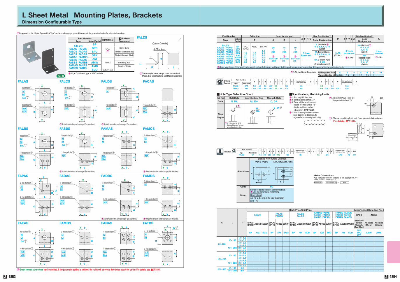
L Sheet Metal Mounting Plates, BracketsDimension Configurable Type

Part Number MMaterial SSurface TreatmentType Material Symbol

FALZSFALAS FAPASFALCS FADASFALDS FADBSFACAS FAMDSFALBS FAEASFASBS FAMBSFAMAS FANASFAMCS FATBS

SP

SPCCE

-

SPB Black Oxide

SPU Trivalent Chromate (Clear)

SPK Trivalent Chromate (Black)

AMA5052

-

AMW Anodize (Clear)

AMB Anodize (Black)

SUD SUS304(2B) -

E�4.5, 6.0 thickness type is SPHC material.

EAs opposed to the "Center Symmetrical Type" on the previous page, general tolerance is the guaranteed value for external dimensions.

Part Number- T - A - B - L - X - F - H - G - Hole Specification1

Code, Nominal Value - D - J - Y - V - S - W - Hole Specification2 Code, Nominal Value - K

Type - Material Symbol

FALAS - SPB - T1.6 - A30 - B30 - L30 - X15 - H20 - N5 - Y15 - S15 - NA6FAMBS - AM - T1.5 - A80 - B60 - L60 - X50 - F0 - H70 - N4 - Y15 - V30 - S20 - W20 - NA5

E�There may be some hanger holes on anodized FALZS.(See Specifications and Machining Limits)

FALZS

FALAS FALCS FALDS FACAS

FALBS FASBS FAMAS FAMCS

FAPAS FADAS FADBS FAMDS

FAEAS FAMBS FANAS FATBS

E�Slotted hole direction can be changed (See alterations). E�Slotted hole direction can be changed (See alterations).

E�Slotted hole direction can be changed (See alterations). E�Slotted hole direction can be changed (See alterations).

E�Slotted hole direction can be changed (See alterations).E�Slotted hole direction can be changed (See alterations).

S

Y

X

H

LHole specification2NAMA

AB

Hole specification1

+0.2 0

NMDA

Hole specification2NA

X

HS

K

Y

Hole specification1NMDA

+0.2 0

X

HJ

Hole specification2NA

SK

Y

Hole specification1N

2 - Hole specification2NAMA

S

VY

AB

X

HS

VY

2 - Hole specification2NAMA

Hole specification1NMDA

L

+0.2 0

VY

X

KS

H

2 - Hole specification2NA

Hole specification1NMDA

+0.2 0

2 - Hole specification2NAMA

S

VY

FH

X

2 - Hole specification1NM

VY

KS

2 - Hole specification2NA

F

H

X

2 - Hole specification1NM

AB

F

HG

X2 - Hole specification1NM

2 - Hole specification2NAMA S

VY

L

HG

X2 - Hole specification1NM

2 - Hole specification2NAMA S

VY VY

KS

2 - Hole specification2NA

HG

X2 - Hole specification1NM

VY

KS

2 - Hole specification2NA

FJ

HX

2 - Hole specification1N

BA

X

H

Hole specification1NM

4 - Hole specification2NAMA

V

WS

Y

DA

L

+0.2 0

2 - Hole specification1

4 - Hole specification2

NM

NAMA

F

H

V

WS

X

Y

F

HG

X

4 - Hole specification2NAMA

V

WS

Y

4 - Hole specification1NM

H

G

FX

D

S

VY

4 - Hole specification1NM

2 - Hole specification2NAMA

+0.2 0

L

4-C2 or less

T

A

B

r

(Common Dimension)

eGreen colored parameters can be omitted. If the parameter setting is omitted, the holes will be evenly distributed about the center. For details, see dP.1834.

b

bbb f

g

bg

f

5 Ø3

5

QSpecifications, Machining LimitsE1. Burr height 0.1 or lessE2. Bend angle tolerance ±1°E3. There will be scratches and

bulges by Press Brake. For details and bend radius information, DP.1832.

E�4. Slotted holes may be shaped as shown below depending on dimensions. (No negative effects on mounting functionality) E6. There are machining limits on b, f, and g shown in below diagram.

For details, dP.1834.

E5. Anodized FALZS There are hanger holes above T4.

QHole Type Selection ChartHole Type Bolt Hole Tapped Holes (Coarse Thread) Through Hole

Code N, NA M, MA D, DA

Shape

Diagram

deMMA

D • DA +0.2 0

E�For d dimension, see "N, NA Machining Dimensions" on lower section of specification chart.

Part Number Selection 1mm IncrementX F H G

Hole Specification1D J Y V S W

Hole Specification2KType Material

Symbol T A B L Code Designation Code Designation

FALZSFALAS FAPASFALCS FADASFALDS FADBSFACAS FAMDSFALBS FAEASFASBS FAMBSFAMAS FANASFAMCS FATBS

SPSPBSPUSPKAM

AMWAMBSUD

SPCC(SPHC)

1.62.33.24.56.0

A5052

1.52.03.04.05.0

SUS304

1.01.52.03.04.05.0

20

~

200

EFor T6.0

~300

15

~

200

EFor T6.0

20~

10

~

200

EFor T6.0

20~

0.1mm Increment

N (Bolt Hole)E0, 3, 4, 5, 6, 8, 10

(Select)

3~30(0.5 Inc.)

0.1mm Increment

EJ≤Nx5

NA (Bolt Hole)E0, 3, 4, 56, 8, 10(Select) 0.1mm

Increment

EK≤NAx5

M (Tapped Holes)0, 3, 4, 5, 6, 8, 10

(Select) MA(Tapped Holes)

0, 3, 4, 56, 8, 10(Select)

DA (Through Hole)3~30

(0.5mm Increment)

EHoles may deform if the hole locations are too close to the ends and bends, but they will be machined as specified if they are within the machining limits.

EN, NA machining dimensions N, NA specified Value 0 3 4 5 6 8 10Through Hole Dia. (d) (No Hole) 3.5 4.5 5.5 6.5 9 11

Alterations

Slotted Hole Angle ChangeFALCS, FALDS FASBS, FAMCSFADBS, FAMDS

Code RC

Spec.

Slotted holes are changed as shown above.ENote the dimensions relationship

Add RC at the end of the type designation(Ex.)~-RC

S

B

Y

V

Y

S

B

Ordering Code

Part Number- T - A - B - L - X - F - H - G - Hole Specification1

Code, Nominal Value - D - J - Y - V - S - W - Hole Specification2

Code, Nominal Value - K - (RC)Type - Material Symbol

FALCS - SP - T1.6 - A30 - B30 - L30 - X15 - H20 - N5 - Y15 - S15 - NA3 - K2 - RC

A L T

Body Price Unit Price Surface Treatment Charge (Body Price+)

FALZS FALASFACAS

FALBSFALCS

FAMAS FAPASFASBS FADASFALDS FAEAS

FAMBS FAMCSFADBS FATBSFANAS FAMDS

SPCC A5052

SPCCSPHC A5052 SUS304 SPCC

SPHC A5052 SUS304 SPCCSPHC A5052 SUS304 SPCC

SPHC A5052 SUS304 SPCCSPHC A5052 SUS304

Black Oxide Trivalent

Chromate (Clear, Black)

Anodize (Clear)

Anodize (Black)

SP AM SUD SP AM SUD SP AM SUD SP AM SUD SP AM SUDSPBSPUSPK

AMW AMB

20~100

10~1001.0~1.62.0~3.24.0~6.0

101~2001.0~1.62.0~3.24.0~6.0

101~200

10~1001.0~1.62.0~3.24.0~6.0

101~2001.0~1.62.0~3.24.0~6.0

201~300 10~100 6.0 - - - - - - - - - - - -101~200 6.0 - - - - - - - - - - - -

• Price CalculationsAdd surface treatment charges to the body prices.(Ex.) For FALZS-SPU-T1.6-A100-B50-L50,

Main Body Price + Surface Treatment Charge = Price