Embed Size (px)
Citation preview
i
y,*
i '
,1#,.1
L.
N ASATechnicalMemorandum
NASA TM- 100390
ROLLING CONTACT FATIGUE OF SURFACEMODIFIED 440C USING A "GE-POLYMET"TYPE DISC ROD TEST RIG
By Robert L. Thorn
Materials and Processes Laboratory
Science and Engineering Directorate
March 1989
(NASA-TM-IO0390 ROLLING CONTACT FATIGUE OF
SUAFACC M_OIFTEO 440C U_ING A 'Ge-PqLYMET"
TYPE _ISC RO_ TEST RIG (NASA) 23 pCSCL IIF
GJI2_
NQO-20200
NASANational Aeronautics andSpace Administration
George C. Marshall Space Flight Center
MSFC - Form 3190 (Rev. May 1983)
https://ntrs.nasa.gov/search.jsp?R=19900010884 2018-05-18T02:10:38+00:00Z
r ¸_
#
'1¢
r
1.
4.
TECHNICAL REPORT STANDARD TITLE PAGE
REPORT NO.
NASA TM-100390 2. GOVERNMENT ACCESSION NO.
TITLEANDSUBTITLE
Roiling Contact Fatigue of Surface Modified 440C
Using a "Ge-Polymet" Type Disc Rod Test Rig
3, RECIPIENToS CATALOG NO.
,5. REPORT DATE
March 1989
6. PERFORMING ORGANIZATION CODE
7. AUTHOR(S') 8.PERFORMING ORGANIZATION REPORr #Robert h. Thorn
9. PERFORMING ORGANIZATION NAME AND ADDRESS 10. WORK UNIT NO.
i2,
George C. Marshall Space Flight Center
Marshall Space Flight Center, Alabama 35812
SPONSORING AGENCY NAME AND ADDRESS
National Aeronautics and Space Administration
Washington, D.C. 20546
11. CONTRACT OR GRANT NO,
_3. TYPE OF REPORV_ PER,OD COVERED
Technical Memorandum
'14. SPONSORING AGENCY CODE
15. SUPPLEMENTARY NOTES
Prepared by Materials and Processes Laboratory, Science and Engineering Directorate.
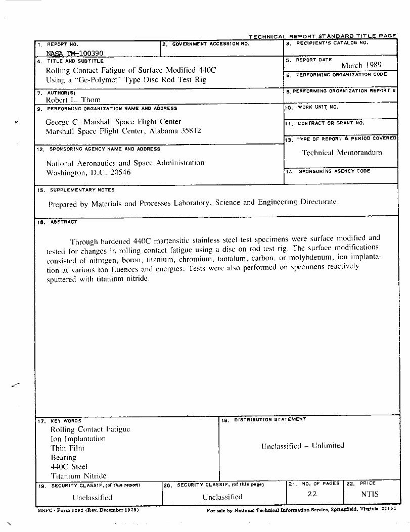
16. ABSTRACT
Through hardened 440C martensitic stainless steel test specimens were surface modified and
tested for changes in rolling contact fatigue using a disc on rod test rig. The surface modifications
consisted of nitrogen, boron, titanium, chromium, tantalum, carbon, or molybdenum, ion implanta-
tion at various ion fluences and energies. Tests were also performed on specimens reactively
sputtered with titanium nitride.
17. KE'Y WORDS
Rolling Contact Fatigue
Ion Implantation
Thin Film
Bearing440C Steel
Titanium Nitride
19. SECURITY CLASSIF. (o( thl= report;
Unclassified
MSFC - Form 3292 (Rev. December 1111:1)
18. DISTRIBUTION STATEMENT
Unclassified - Unlimited
SECURITY CLASSIF. (ottht= 1_8-) ]21. NO. OF PAGES [ 22. PRICE
i
Unclassified 2 2 ]NTIS
For sale by National Technical Information Service, Springfield, V_ 2 2151
\

Z:%/_-Z Z
i
TABLE OF CONTENTS
Page
INTRODUCTION .............................................................................................. 1
EXPERIMENTAL PROCEDURE ........................................................................... 2
A. Test Specimens .................................................................................... 2B. Surface Modifications ............................................................................ 2
C. Rolling Contact Fatigue Testing ................................................................. 3
RESULTS ........................................................................................................ 3
DISCUSSION OF RESULTS ................................................................................. 4
CONCLUSIONS ................................................................................................ 5
REFERENCES .................................................................................................. 6
oo°
111PRECEDING PAGE BLANK NOT FILMED

LIST OF ILLUSTRATIONS
i
J
Figure
1.
2.
.
.
.
.
,
,
.
Title
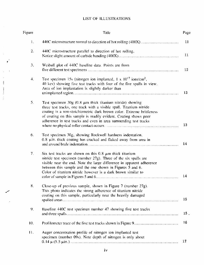
440C microstructure normal to direction of hot rolling (400X) ............................
440C microstructure parallel to direction of hot rolling.
Notice slight amount of carbide banding (400X) .............................................
Weibull plot of 440C baseline data. Points are from
five different test specimens ....................................................................
Test specimen 15s (nitrogen ion implanted, I x 1017 ions/cm 2,
40 kev) showing five test tracks with four of the five spalls in view.
Area of ion implantation is slightly darker than
unimplanted region ...............................................................................
Test specimen 30g (0.8 t.tm thick titanium nitride) showing
three test tracks, one track with a visible spall. Titanium nitride
coating is a non-stoichiometric dark brown color. Extreme brittleness
of coating on this sample is readily evident. Coating shows poor
adherence in test tracks and even in area surrounding test tracks
where no physical roller contact occurs .......................................................
Page
11
11
12
13
13
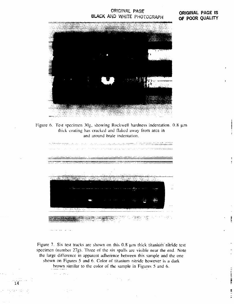
Test specimen 30g, showing Rockwell hardness i_ndentation.
0.8 Ixin. thick coating has cracked and flaked away from area inand around brale indentation .................................................................... 14
Six test tracks are shown on this 0.8 I,.tm thick titanium
nitride test specimen (number 27g). Three of the six spalls are
visible near the end. Note the large difference in apparent adherence
between this sample and the one shown in Figures 5 and 6.Color of titanium nitride however is a dark brown similar to
color of sample in Figures 5 and 6 .............................................................. 14
Close-up of previous sample, shown in Figure 7 (number 27g).
This photo indicates the strong adherence of titanium nitride
coating on this sample, particularly near the heavily damaged
spailed areas ....................................................................................... 15
Baseline 440C test specimen number 47 showing five test tracks
and three spalls .................................................................................... 15
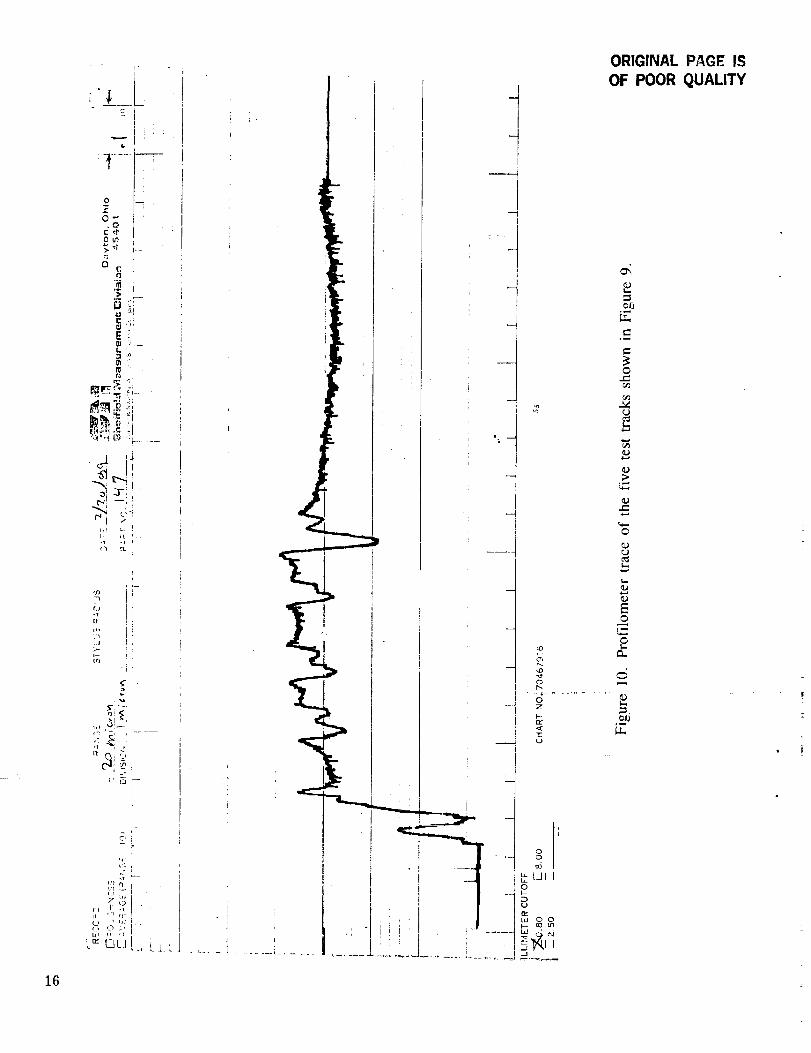
Profilometer trace of the five test tracks shown in Figure 9 ................................. 16
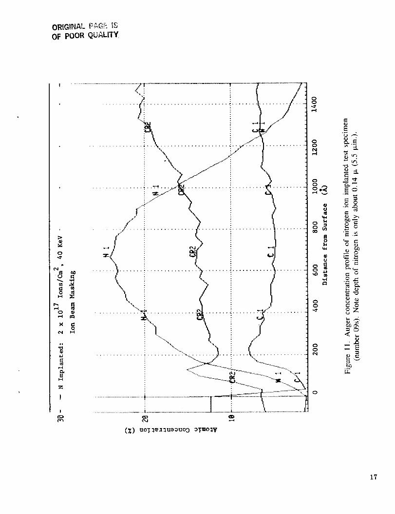
Auger concentration profile of nitrogen ion implanted test
specimen (number 0%). Note depth of nitrogen is only about
0.14 ix (5.5 l_in.) ................................................................................. 17
iv

±=: : :
LIST OF TABLES
Table
1.
2.
3.
4.
Title Page
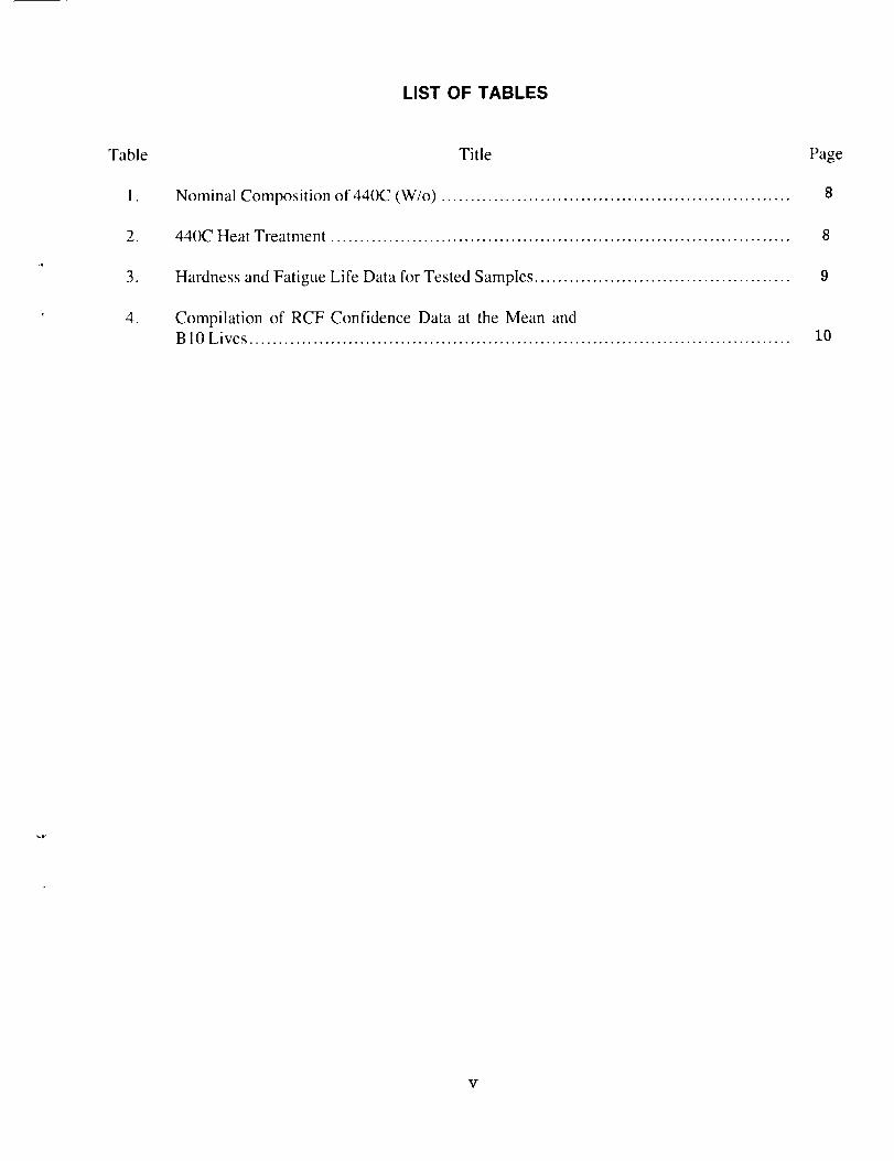
Nominal Composition of 440C (W/o) ............................................................ 8
440C Heat Treatment ............................................................................... 8
Hardness and Fatigue Life Data for Tested Samples ............................................ 9
Compilation of RCF Confidence Data at the Mean andB 10 Lives ............................................................................................. 10
V

TECHNICAL MEMORANDUM
ROLLING CONTACT FATIGUE OF SURFACE MODIFIED 440C USING A
"GE-POLYMET" TYPE DISC ROD TEST RIG
INTRODUCTION
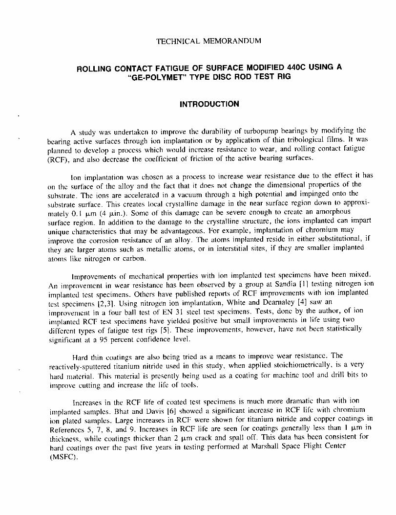
A study was undertaken to improve the durability of turbopump bearings by modifying the
bearing active surfaces through ion implantation or by application of thin tribological films. It was
planned to develop a process which would increase resistance to wear, and rolling contact fatigue
(RCF), and also decrease the coefficient of friction of the active bearing surfaces.
Ion implantation was chosen as a process to increase wear resistance due to the effect it has
on the surface of the alloy and the fact that it does not change the dimensional properties of the
substrate. The ions are accelerated in a vacuum through a high potential and impinged onto the
substrate surface. This creates local crystalline damage in the near surface region down to approxi-
mately 0. ! I_m (4 pan.). Some of this damage can be severe enough to create an amorphous
surface region. In addition to the damage to the crystalline structure, the ions implanted can impart
unique characteristics that may be advantageous. For example, implantation of chromium may
improve the corrosion resistance of an alloy. The atoms implanted reside in either substitutional, if
they are larger atoms such as metallic atoms, or in interstitial sites, if they are smaller implanted
atoms like nitrogen or carbon.
Improvements of mechanical properties with ion implanted test specimens have been mixed.
An improvement in wear resistance has been observed by a group at Sandia [1] testing nitrogen ion
implanted test specimens. Others have published reports of RCF improvements with ion implanted
test specimens [2,3]. Using nitrogen ion implantation, White and Dearnaley [4] saw an
improvement in a four ball test of EN 31 steel test specimens. Tests, done by the author, of ion
implanted RCF test specimens have yielded positive but small improvements in life using two
different types of fatigue test rigs [5]. These improvements, however, have not been statistically
significant at a 95 percent confidence level.
Hard thin coatings are also being tried as a means to improve wear resistance. The
reactively-sputtered titanium nitride used in this study, when applied stoichiometrically, is a very
hard material. This material is presently being used as a coating for machine tool and drill bits to
improve cutting and increase the life of tools.
Increases in the RCF life of coated test specimens is much more dramatic than with ion
implanted samples. Bhat and Davis [6] showed a significant increase in RCF life with chromium
ion plated samples. Large increases in RCF were shown for titanium nitride and copper coatings in
References 5, 7, 8, and 9. increases in RCF life are seen for coatings generally less than I I_m in
thickness, while coatings thicker than 2 I_m crack and spall off. This data has been consistent for
hard coatings over the past five years in testing performed at Marshall Space Flight Center
(MSFC).
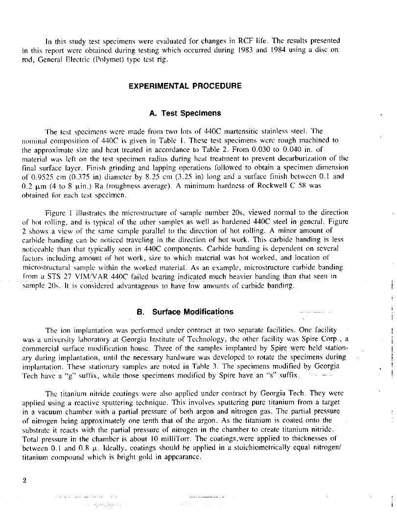
In this study test specimens were evaluated for changes in RCF life. The results presented
in this report were obtained during testing which occurred during 1983 and 1984 using a disc on
rod, General Electric (Polymet) type test rig.
EXPERIMENTAL PROCEDURE
A. Test Specimens
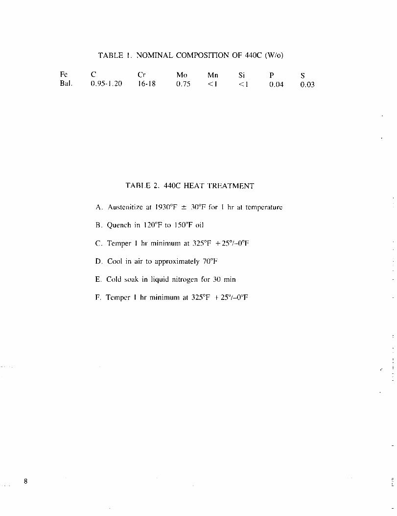
The test specimens were made from two lots of 440C martensitic stainless steel. The
nominal composition of 440C is given in Table !. These test specimens were rough machined to
the approximate size and heat treated in accordance to Table 2. From 0.030 to 0.040 in. of
material was left on the test specimen radius during heat treatment to prevent decarburization of the
final surface layer. Finish grinding and lapping operations followed to obtain a specimen dimension
of 0.9525 cm (0.375 in) diameter by 8.25 cm (3.25 in) long and a surface finish between 0.1 and
0.2 ixm (4 to 8 l.tin.) Ra (roughness average). A minimum hardness of Rockwell C 58 was
obtained for each test specimen.
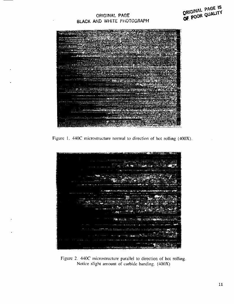
Figure 1 illustrates the microstructure of sample number 20s, viewed normal to the direction
of hot rolling, and is typical of the other samples as well as hardened 440C steel in general. Figure
2 shows a view of the same sample parallel to the direction of hot rolling. A minor amount of
carbide banding can be noticed traveling in the direction of hot work. This carbide banding is less
noticeable than that typically seen in 440C components. Carbide banding is dependent on several
factors including amount of hot work, size to which material was hot worked, and location of
microstructural sample within the worked material. As an example, microstructure carbide banding
from a STS 27 VIM/VAR 440C failed bearing indicated much heavier banding than that seen in
sample 20s. It is considered advantageous to have low amounts of carbide banding.
B. Surface Modifications
The ion implantation was performed under contract at two separate facilities. One facility
was a university laboratory at Georgia Institute of Technology, the other facility was Spire Corp., a
commercial surface modification house. Three of the samples implanted by Spire were held station-
ary during implantation, until the necessary hardware was developed to rotate the specimens during
implantation. These stationary samples are noted in Table 3. The specimens modified by Georgia
Tech have a "g'" suffix, while those specimens modified by Spire have an "s" suffix.
The titanium nitride coatings were also applied under contract by Georgia Tech. They were
applied using a reactive sputtering technique. This involves sputtering pure titanium from a target
in a vacuum chamber with a partial pressure of both argon and nitrogen gas. The partial pressure
of nitrogen being approximately one tenth that of the argon. As the titanium is coated onto the
substrate it reacts with the partial pressure of nitrogen in the chamber to create titanium nitride.
Total pressure in the chamber is about 10 milliTorr. The coatings.were applied to thicknesses of
between 0.1 and 0.8 _. Ideally, coatings should be applied in a stoichiometricaily equal nitrogen/
titanium compound which is bright gold in appearance.
i
i
i
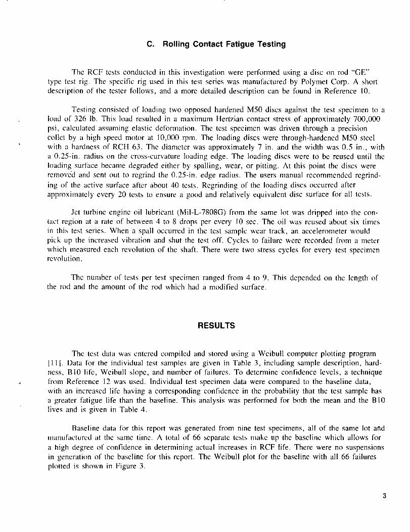
C. Rolling Contact Fatigue Testing
The RCF tests conducted in this investigation were performed using a disc on rod "GE"
type test rig. The specific rig used in this test series was manufactured by Polymer Corp. A short
description of the tester follows, and a more detailed description can be found in Reference 10.
Testing consisted of loading two opposed hardened M50 discs against the test specimen to a
load of 326 lb. This load resulted in a rnaximum Hertzian contact stress of approximately 700,000
psi, calculated assuming elastic deformation. The test specimen was driven through a precision
collet by a high speed motor at 10,000 rpm. The loading discs were through-hardened M50 steel
with a hardness of RCH 63. The diameter was approximately 7 in. and the width was 0.5 in., with
a 0.25-in. radius on the cross-curvature loading edge. The loading discs were to be reused until the
loading surface became degraded either by spalling, wear, or pitting. At this point the discs were
removed and sent out to regrind the 0.25-in. edge radius. The users manual recommended regrind-
ing of the active surface after about 40 tests. Regrinding of the loading discs occurred after
approximately every 20 tests to ensure a good and relatively equivalent disc surface for all tests.
Jet turbine engine oil lubricant (MiI-L-7808G) from the same lot was dripped into the con-
tact region at a rate of between 4 to 8 drops per every 10 sec. The oil was reused about six times
in this test series. When a spall occurred in the test sample wear track, an accelerometer would
pick up the increased vibration and shut the test off. Cycles to failure were recorded from a meter
which measured each revolution of the shaft. There were two stress cycles for every test specimenrevolution.
The number of tests per test specimen ranged from 4 to 9. This depended on the length ofthe rod and the amount of the rod which had a modified surface.
RESULTS
The test data was entered compiled and stored using a Weibull computer plotting program
[11]. Data for the individual test samples are given in Table 3, including sample description, hard-
ness, B10 life, Weibull slope, and number of failures. To determine confidence levels, a technique
from Reference 12 was used. Individual test specimen data were compared to the baseline data,
with an increased life having a corresponding confidence in the probability that the test sample has
a greater fatigue life than the baseline. This analysis was performed for both the mean and the BI0
lives and is given in Table 4.
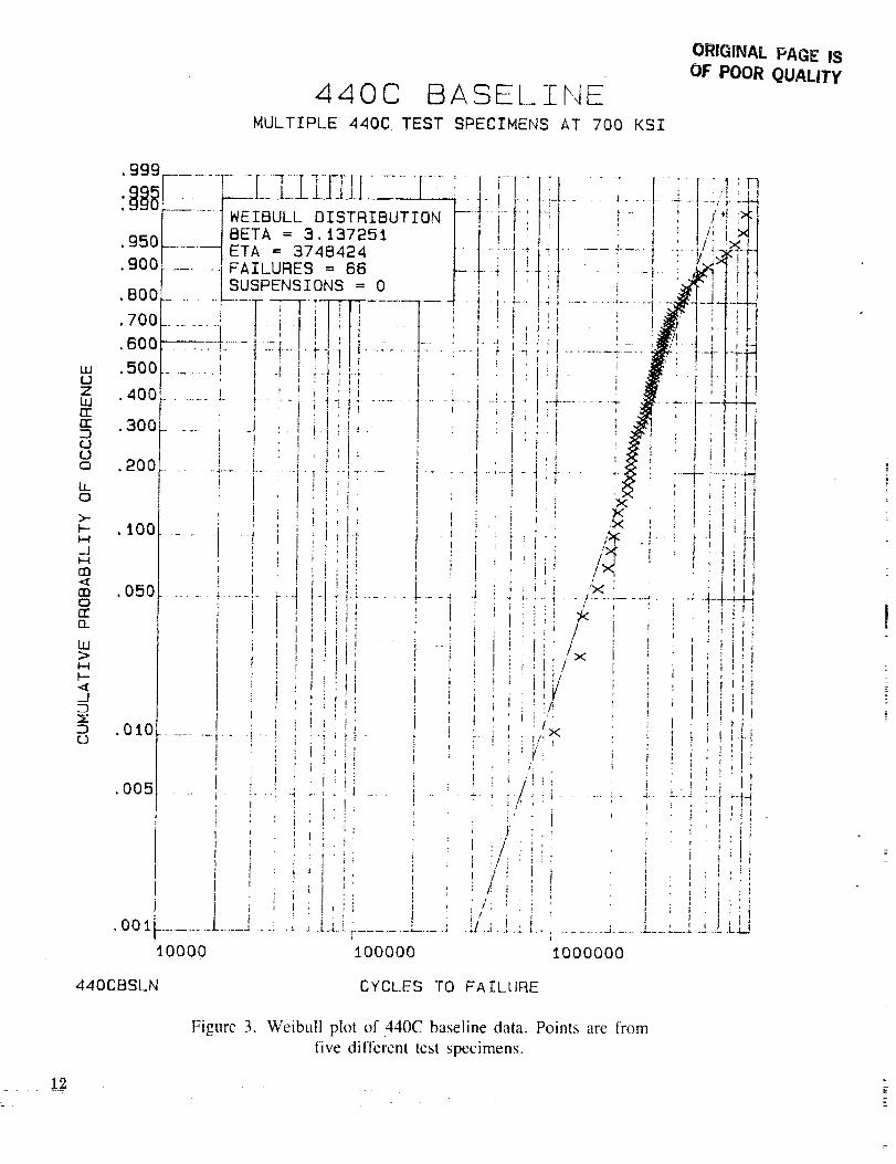
Baseline data for this report was generated from nine test specimens, all of the same lot and
manufactured at the same time. A total of 66 separate tests make up the baseline which allows for
a high degree of confidence in determining actual increases in RCF life. There were no suspensions
in generation of the baseline for this report. The Weibull plot for the baseline with all 66 failures
plotted is shown in Figure 3.
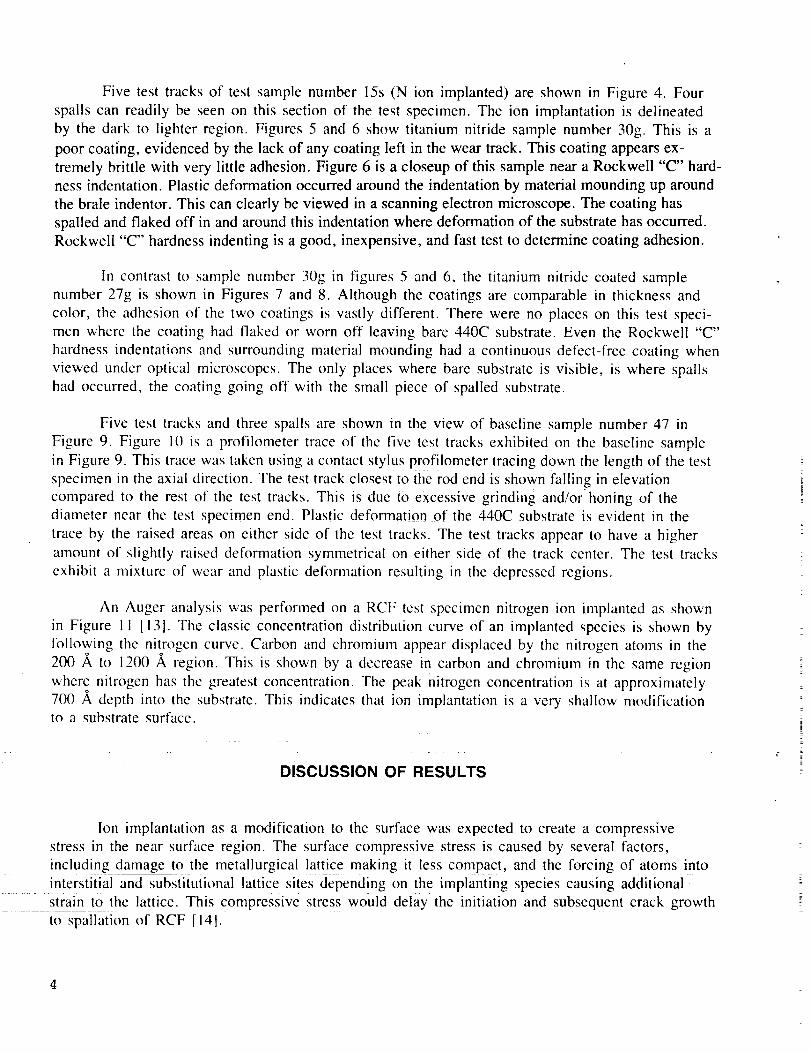
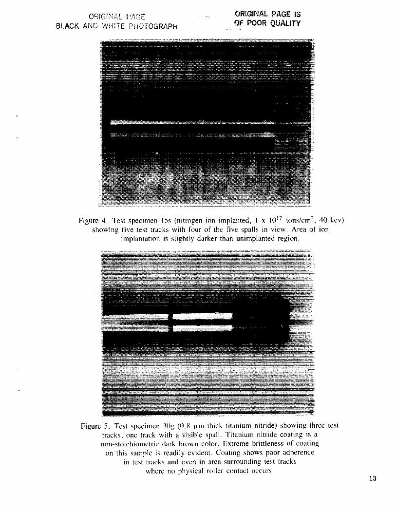
Five test tracksof test samplenumber15s(N ion implanted)are shownin Figure 4. Four
spalls can readily be seen on this section of the test specimen. The ion implantation is delineated
by the dark to lighter region. Figures 5 and 6 show titanium nitride sample number 30g. This is a
poor coating, evidenced by the lack of any coating left in the wear track. This coating appears ex-
tremely brittle with very little adhesion. Figure 6 is a closeup of this sample near a Rockwell "C" hard-
ness indentation. Plastic deformation occurred around the indentation by material mounding up around
the brale indentor. This can clearly be viewed in a scanning electron microscope. The coating has
spalled and flaked off in and around this indentation where deformation of the substrate has occurred.
Rockwell "C" hardness indenting is a good, inexpensive, and fast test to determine coating adhesion.
In contrast to sample number 30g in figures 5 and 6, the titanium nitride coated sample
number 27g is shown in Figures 7 and 8. Although the coatings are comparable in thickness and
color, the adhesion of the two coatings is vastly different. There were no places on this test speci-
men where the coating had flaked or worn off leaving bare 440C substrate. Even the Rockwell "C"
hardness indentations and surrounding material mounding had a continuous defect-free coating when
viewed under optical microscopes. The only places where bare substrate is visible, is where spalls
had occurred, the coating going off with the small piece of spalled substrate.
Five test tracks and three spalls are shown in the view of baseline sample number 47 in
Figure 9. Figure 10 is a profilometer trace of the five test tracks exhibited on the baseline sample
in Figure 9. This trace was taken using a contact stylus profilometer tracing down the length of the test
specimen in the axial direction. The test track closest to the rod end is shown falling in elevationcompared to the rest of the test tracks. This iS dUe to excessive grinding and/or honing of the
diameter near the test specimen end. Plastic deformation of the 440C substrate is evident in the
trace by the raised areas on either side of the test tracks. The test tracks appear to have a higher
amount of slightly raised deformation symmetrical on either side of the track center. The test tracks
cxhibit a mixture of wear and plastic deformation resulting in the depressed regions.
An Auger analysis was performed on a RCF test specimen nitrogen ion implanted as shown
in Figure 1 I [13]. The classic concentration distribution curve of an implanted species is shown by
following the nitrogen curve. Carbon and chromium appear displaced by the nitrogen atoms in the
200 ,_ to 1200 ,_ region. This is shown by a decrease in carbon and chromium in the same region
where nitrogen has the greatest concentration. The peak nitrogen concentration is at approximately
700 A depth into the substrate. This indicates that ion implantation is a very shallow modificationto a substrate surface.
DISCUSSION OF RESULTS
Ion implantation as a modification to the surface was expected to create a compressive
stress in the near surface region. The surface compressive stress is caused by several factors,
including damage to the metallurgical lattice making it less compact, and the forcing of atoms into
interstitial and substitutional lattice sites depending on the implanting species causing additional
Strain to the lattice. This compressive stress would delay the initiation and subsequent crack growth
to spallation of RCF [141.
4
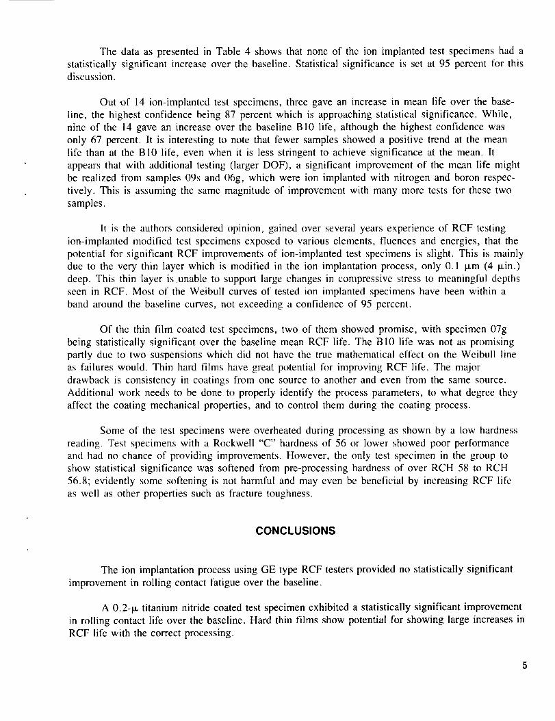
The data as presented in Table 4 shows that none of the ion implanted test specimens had a
statistically significant increase over the baseline. Statistical significance is set at 95 percent for this
discussion.
Out ,of 14 ion-implanted test specimens, three gave an increase in mean life over the base-
line, the highest confidence being 87 percent which is approaching statistical significance. While,
nine of the 14 gave an increase over the baseline BI0 life, although the highest confidence was
only 67 percent. It is interesting to note that fewer samples showed a positive trend at the mean
life than at the BI0 life, even when it is less stringent to achieve significance at the mean. It
appears that with additional testing (larger DOF), a significant improvement of the me, an life might
be realized from samples 09s and 06g, which were ion implanted with nitrogen and boron respec-
tively. This is assuming the same magnitude of improvement with many more tests for these two
samples.
It is the authors considered opinion, gained over several years experience of RCF testing
ion-implanted modified test specimens exposed to various elements, fluences and energies, that the
potential for significant RCF improvements of ion-implanted test specimens is slight. This is mainly
due to the very thin layer which is modified in the ion implantation process, only 0.1 la,m (4 p.in.)
deep. This thin layer is unable to support large changes in compressive stress to meaningful depths
seen in RCF. Most of the Weibull curves of tested ion implanted specimens have been within a
band around the baseline curves, not exceeding a confidence of 95 percent.
Of the thin film coated test specimens, two of them showed promise, with specimen 07g
being statistically significant over the baseline mean RCF life. The Bi0 life was not as promising
partly due to two suspensions which did not have the true mathematical effect on the Weibull line
as failures would. Thin hard films have great potential for improving RCF life. The major
drawback is consistency in coatings from one source to another and even from the same source.
Additional work needs to be done to properly identify the process parameters, to what degree they
affect the coating mechanical properties, and to control them during the coating process.
Some of the test specimens were overheated during processing as shown by a low hardness
reading. Test specimens with a Rockwell "C" hardness of 56 or lower showed poor performance
and had no chance of providing improvements. However, the only test specimen in the group to
show statistical significance was softened from pre-processing hardness of over RCH 58 to RCH
56.8; evidently some softening is not harmful and may even be beneficial by increasing RCF life
as well as other properties such as fracture toughness.
CONCLUSIONS
The ion implantation process using GE type RCF testers provided no statistically significant
improvement in rolling contact fatigue over the baseline.
A 0.2-_L titanium nitride coated test specimen exhibited a statistically significant improvement
in roiling contact life over the baseline. Hard thin films show potential for showing large increases in
RCF life with the correct processing.
REFERENCES
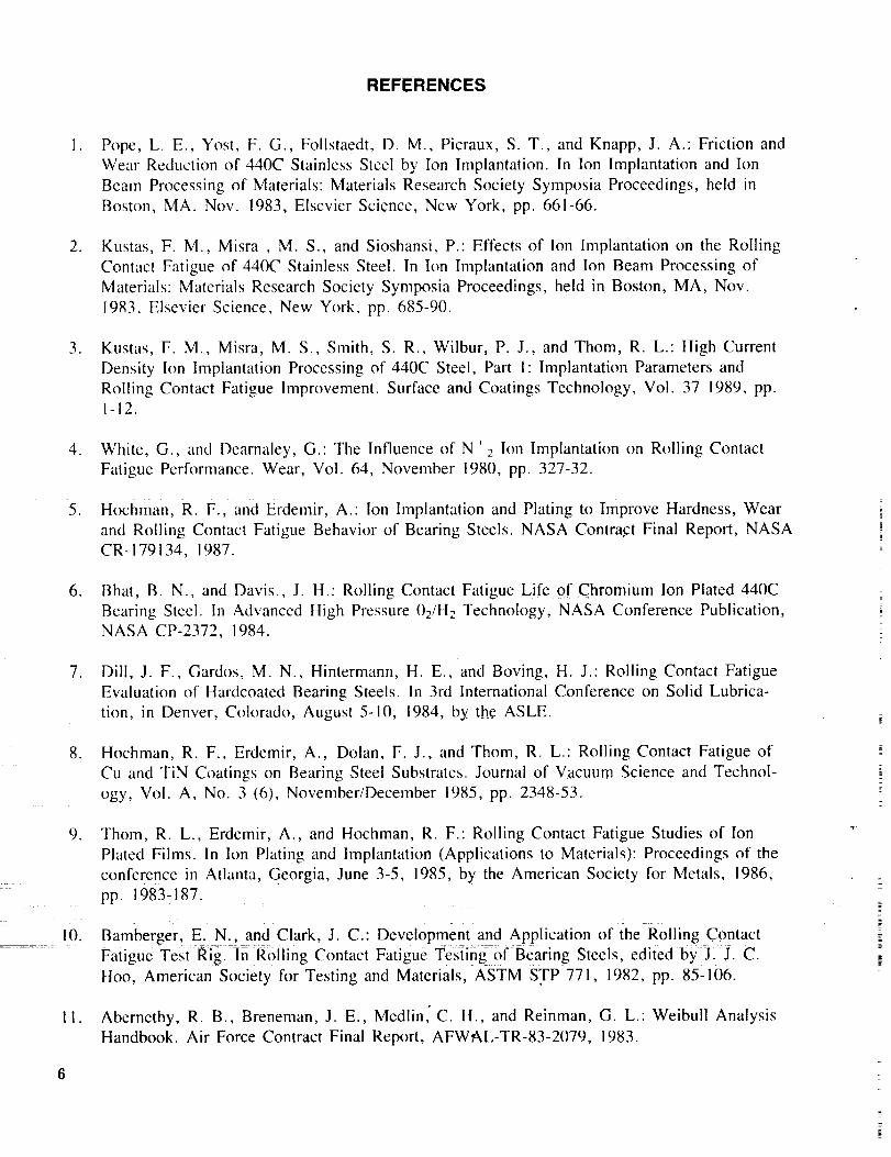
I . Pope, L. E., Yost, F. G., Follstaedt, D. M., Picraux, S. T., and Knapp, J. A.: Friction and
Wear Reduction of 440C Stainless Steel by Ion Implantation. In Ion Implantation and Ion
Beam Processing of Materials: Materials Research Society Syrnposia Proceedings, held in
Boston, MA. Nov. 1983, Elsevier Science, New York, pp. 661-66.
, Kustas, F. M., Misra , M. S., and Sioshansi, P.: Effects of Ion Implantation on the Rolling
Contact Fatigue of 440C Stainless Steel. In Ion Implantation and Ion Beam Processing of
Materials: Materials Research Society Symposia Proceedings, held in Boston, MA, Nov.
1983, Elsevier Science, New York, pp. 685-90.
. Kustas, F. M., Misra, M. S., Smith, S. R., Wilbur, P. J., and Thom, R. L.: High Current
Density Ion Implantation Processing of 440C Steel, Part l" Implantation Parameters and
Roiling Contact Fatigue Improvement. Surface and Coatings Technology, Vol. 37 1989, pp.1-12.
4. White, G and Dearnaley, G.: The Influence of N•, 2 Ion Implantation on Roiling Contact
Fatigue Performance. Wear, Vol. 64, November 1980, pp. 327-32.
5. Hochman, R. F., and Erdemir, A.: Ion Implantation and Plating to Improve Hardness, Wear
and Rolling Contact Fatigue Behavior of Bearing Steels. NASA Contract Final Report, NASA
CR-179134, 1987.
6. Bhat, B. N., and Davis., J. H.: Roiling Contact Fatigue Life of Chromium Ion Plated 440C
Bearing Steel. In Advanced High Pressure 02/H2 Technology, NASA Conference Publication,
NASA CP-2372, 1984.
, Dill, J. F., Gardos, M. N., Hintermann, H. E., and Boving, H. J." Rolling Contact Fatigue
Evaluation of Hardcoated Bearing Steels. In 3rd International Conference on Solid Lubrica-
tion, in Denver, Colorado, August 5-10, 1984, by the ASLE.
. Hochman, R. F., Erdemir, A., Dolan, F. J., and Thorn, R. L.: Rolling Contact Fatigue of
Cu and TiN Coatings on Bearing Steel Substrates. Journal of Vacuum Science and Technol-
ogy, Vol. A, No. 3 (6), November/December 1985, pp. 2348-53.
9. Thom, R. L., Erdemir, A., and Hochman, R. F.: Rolling Contact Fatigue Studies of Ion
Plated Films. In Ion Plating and Implantation (Applications to Materials): Proceedings of the
conference in Atlanta, Georgia, June 3-5, 1985, by the American Society for Metals, 1986,
pp. 1983-187.
!0. Bamberger, E_ N.,and Clark, J. C.: Development and Application of the Rolling Contact
......... Fatigue Test Rig. In Rolling Contact Fatigue Testin_=0fBearing Steels, edited byL J. C.
Hoo, American Society for Testing and Materials, ASTM STP 771, 1982, pp. 85-106.
11. Abernethy, R. B., Breneman, J. E., Medlin, C. H., and Reinman, G. L. Weibull Analysis
Handbook. Air Force Contract Final Report, AFWAL-TR-83-2079, 1983.
6
t
12.
13.
14.
Report of ASTM Committee on Fatigue, E-9. By C. A. Moyer, Chairman. The Weibull Dis-
tribution Function for Fatigue Life. Materials Research and Standards. American Society for
Testing and Materials, May 1962, pp. 405-411.
Kustas, F. M., and Misra, M. S.: Ion Implantation of 440C RCF Test Specimens. NASA
Contract Final Report, Contract NAS8-35055, 1983.
Bower, A. F.: The Influence of Crack Face Friction and Trapped Fluid on Surface Initiated
Rolling Contact Fatigue Cracks. Transactions of the ASME, Vol. 10, October 1988, pp.704-71 !.
Fc
Bal.
TABLE I. NOMINAL COMPOSITION OF 440C (W/o)
C Cr Mo Mn Si P
0.95-1.20 16-18 0.75 <1 <1 0.04
S
0.03
TABLE 2. 440C HEAT TREATMENT
A. Austenitize at 1930°F + 30°F for 1 hr at temperature
B. Quench in 120°F to 150°F oil
C. Temper I hr minimum at 325°F +25°/-0°F
D. Cool in air to approximately 70°F
E. Cold soak in liquid nitrogen for 30 min
F. Temper I hr minimum at 325°F +25°/-0°F
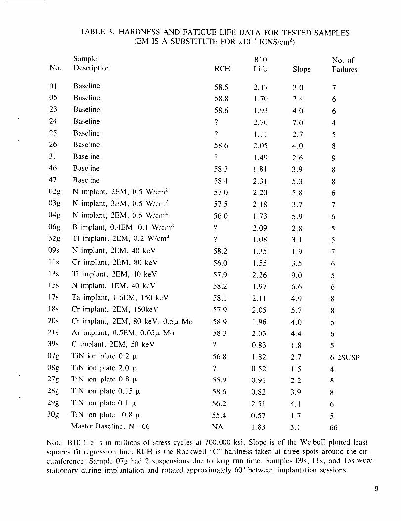
TABLE 3. HARDNESSAND FATIGUE LIFE DATA FOR TESTEDSAMPLES(EM IS A SUBSTITUTEFOR xl0 _7IONS/cm2)
No.
Sample B l0 No. of
Description RCH Life Slope Failures
01
05
23
24
25
26
31
46
47
02g
03g
04g
06g
32g
09s
lls
13s
15s
17s
18s
20s
2Is
39s
07g
08g
27g
28g
29g
30g
Baseline 58.5 2.17 2.0 7
Baseline 58.8 !.70 2.4 6
Baseline 58.6 I .93 4.0 6
Baseline 9 2.70 7.0 4
Baseline 9 1.1 l 2.7 5
Baseline 58.6 2.05 4.0 8
Baseline 9 I .49 2.6 9
Baseline 58.3 1.81 3.9 8
Baseline 58.4 2.31 5.3 8
N implant, 2EM, 0.5 W/cm 2 57.0 2.20 5.8 6
N implant, 3EM, 0.5 W/cm 2 57.5 2.18 3.7 7
N implant, 2EM, 0.5 W/cm z 56.0 1.73 5.9 6
B implant, 0.4EM, 0. I W/cm 2 9 2.09 2.8 5
Ti implant, 2EM, 0.2 W/cm 2 '_ 1.08 3.1 5
N implant, 2EM, 40 keV 58.2 1.35 1.9 7
Cr implant, 2EM, 80 keV 56.0 1.55 3.5 6
Ti implant, 2EM, 40 keV 57.9 2.26 9.0 5
N implant, IEM, 40 keV 58.2 i.97 6.6 6
Ta implant, 1.6EM, 150 keV 58.1 2.1 ! 4.9 8
Cr implant, 2EM, 150keV 57.9 2.05 5.7 8
Cr implant, 2EM, 80 keV. 0.51.t Mo 58.9 1.96 4.0 5
Ar implant, 0.5EM, 0.05_ Mo 58.3 2.03 4.4 6
C implant, 2EM, 50 keV '_ 0.83 1.8 5
TiN ion plate 0.2 I-t 56.8 1.82 2.7 6 2SUSP
TiN ion plate 2.0 IX 9 0.52 !.5 4
TiN ion plate 0.8 Ix 55.9 0.91 2.2 8
TiN ion plate 0.15 Ix 58.6 0.82 3.9 8
TiN ion plate 0.1 _ 56.2 2.51 4.1 6
TiN ion plate 0.8 _ 55.4 0.57 1.7 5
Master Baseline, N = 66 NA 1.83 3.1 66
Note: B10 life is in millions of stress cycles at 700,000 ksi. Slope is of the Weibull plotted least
squares fit regression line. RCH is the Rockwell "C" hardness taken at three spots around the cir-
cumference. Sample 07g had 2 suspensions due to long run time. Samples 09s, i ls, and 13s were
stationary during implantation and rotated approximately 60 ° between implantation sessions.
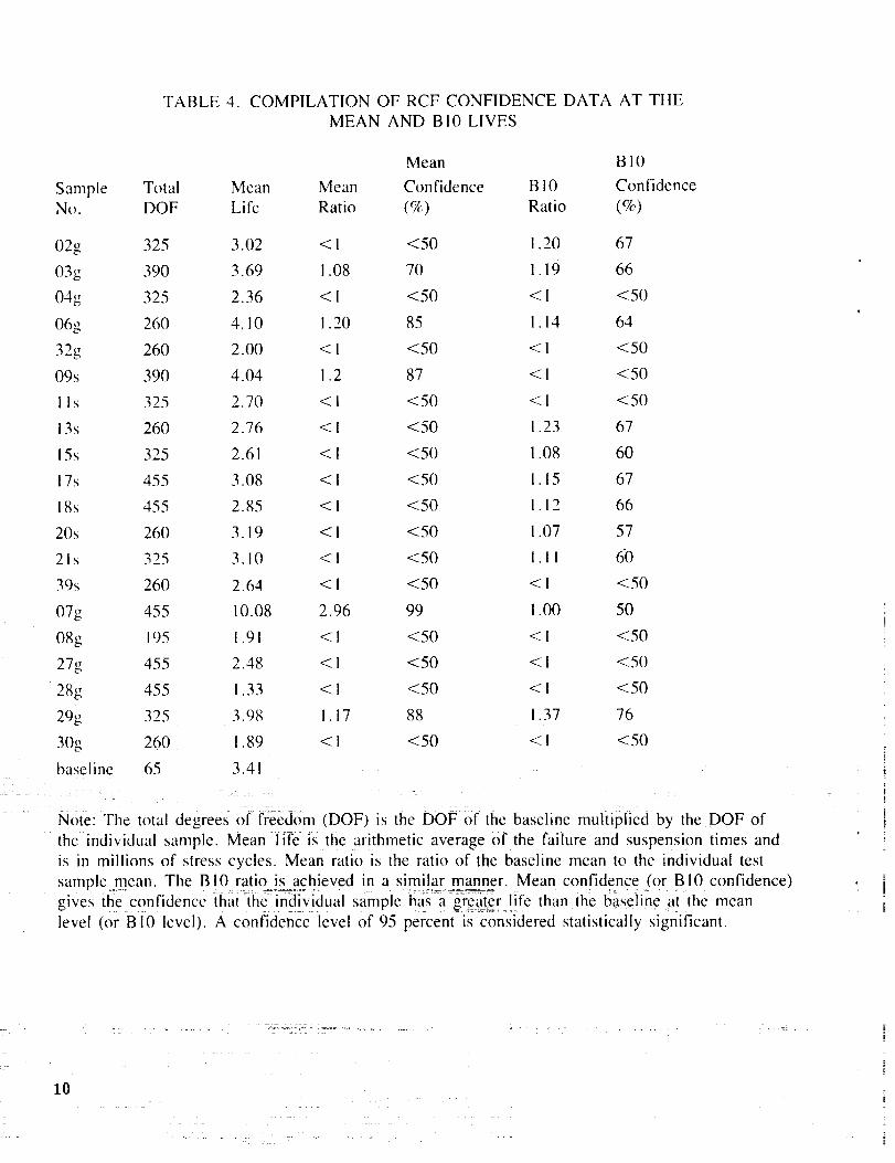
TABLE 4. COMPILATION OF RCF CONFIDENCEDATA AT THEMEAN AND B10 LIVES
Sample Total MeanNo. DOF Life
02g 325 3.02038 390 3.69
048 325 2.36
068 260 4. !0
32g 260 2.OO09s 390 4.04I I s 325 2.70
13s 260 2.76
15s 325 2.61
17s 455 3.08
18s 455 2.8520s 260 3.19
2Is 325 3.10
3% 260 2.64
078 455 10.08
08g 195 1.9I27g 455 2.48
288 455 1.33
29g 325 3.98
30g 260 1.89
baseline 65 3.4 !
Mean
Ratio
<l
I .08
<l
1.20
<1
1.2
<l
<
<
<
<
<
<
<
2.96
<1
<1
<1
1.17
<1
Mean B 10
Confidence B !0 Confidence
(%) Ratio (%)
<50 ! .20 67
70 l. 19 66
<50 < 1 <50
85 I. 14 64
<50 <1 <50
87 < 1 <50
<50 < 1 <50
<50 I .23 67
<50 I .08 60
<50 !. 15 67
<50 I. 12 66
<50 i .07 57
<50 1.11 60
<50 < ! <50
99 1.00 50
<50 < 1 <50
<50 < I <50
<50 < I <50
88 1.37 76
<50 < I <50
Note: The total degrees of freedom (DOF) is the DOF of the baseline multiplied by the DOF of
the individual sample. Mean -lit_e i_s the arithmetic average of the failure and suspension times and
is in millions of stress cycles. Mean ratio is the ratio of the baseline mean to the individual test
sample mean. The B 10 ratkLjs_ach!eved in a simi!ar l_nanner. Mean confidence (or B l0 confidence)gives the confidence that -the-- irid[v[dual sample has a greater life than the baseline at the mean
level (or B10 level). A confidence level of 95 percent is considered statistically significant.
10
i ..... : 121 •
ORIGINAL PAGE
BLACK AND WHITE PHOTOGRAPH
Figure !. 440C microstructure normal to direction of hot rolling (400X).
Figure 2. 440C microstructure parallel to direction of hot rolling.
Notice slight amount of carbide banding. (400X)
11
440C BASFL_ZN£MULTIPLE 440C TEST SPECIMENS AT 700 KSI
ORIGINAL PAGE ISOF POOR QUALITY'
LUUZI,in_n-
UO0
II0
>-
MdMIf)
m0rrD_
Ill
M
_J
_E
CJ
.999
.900
.800
.700
.600
.500
.400
.300
.200
. t00
.050
.0!0
,005
.001 ..........
...... _ -r 7i]-f [ Z_ .I
WEIBULL DISTR !
IBUTIONBETA = 3.137251
! ,
IO000
..... J
100000
I
440CBSLN CYCLES TO FA_LtlRE
I
................L] .....i+JI000000
Figure 3. Weibull plot of 440C baseline data. Points are from
five different test specimens.
12
ORIGINAL _' __'_r ? V,._ C.
BLACK AND WHITE PHOFOGRAPH
ORIGINAL PAGE IS
OF POOR QUALITY
!:
Figure 4. Test specimen 15s (nitrogen ion implanted, I x l017 ionslcm 2, 40 kev)
showing five test tracks with four of the five spails in view. Area of ion
implantation is slightly darker than unimplanted region.
Figure 5. Test specimen 30g (0.8 p.m thick titanium nitride) showing three test
tracks, one track with a visible spall. Titanium nitride coating is a
non-stoichiometric dark brown color. Extreme brittleness of coating
on this sample is readily evident. Coating shows poor adherence
in test tracks and even in area surrounding test tracks
where no physical roller contact occurs.13
ORIGINAL PAOE'
BLACK AND W_HITE PHOTOGRAPHORIGINAL PAGE IS
OF POOR QUALITY
..................... .......
Figure 6. Test specimen 30g, showing Rockwell hardness indentation. 0.8 [J,m
thick coating has cracked and flaked away from area inand around brale indentation.
'7 7 .................... _ -7 ' ......... L_ ...5--_..-L_
: _ z :zsz
i4
Figure 7. Six test tracks are shown on this 0.8 _m thick titanium nitride test
specimen (number 27g). Three of the six spalls are visible near the end. Note
the large difference in apparent adherence between this sample and the one
shown on Figures 5 and 6. Color of titanium nitride however is a dark
brown similar to the color of the sample in Figures 5 and 6.

ORIGINAl..- PA_F?_BLACK A_D _HjT_ _ ,,- ..
- 1:H u.T_O_RAPH
ORIQINAL PAGE IS
POOR QUALITY
Figure 8. Close-up of previous sample, shown in Figure 7 (number 27g). This photo
indicates the strong adherence of titanium nitride coating on this sample,
particularly near the heavily damaged spalled areas.
Figure 9. Baseline 440C test specimen number 47
showing five test tracks and three spalls.
15
¢" ,
.o0 o
Cq"
t--G :
nCrj
>
_'il
f,. 't
t-...; =) :r! L
it .,T -ri "1 _1_
i., i-1u
2t.j :.
i- I :
f -
fl -_
,_, 3!2-'
I' (.3 _-
I
t
<F, 0_
,L_ w
l
P
L
f •
m
ORIGINAL PAGE IS
OF POOR QUALITY
LL,
O
_3
;>
16
OF pOOR QUALITY
E
"0
._ c_
-c2
_._
o ._"= _.,c_
c o_z
• e'_
© c
[..t.,
1"/
APPROVAL
ROLLING CONTACT FATIGUE OF SURFACE MODIFIED 440CUSING A "GE-POLYMET" TYPE DISC ROD TEST RIG
By Robert L. Thom
The infl)rmation in this report has been reviewed for technical content. Review of any
information concerning Department of Defense or nuclear energy activities or programs has been
made by the MSFC Security Classification Officer. This report, in its entirety, has been determinedto be unclassified.
P.H. SCHUERER
Director, Materials and Processes Laboratory
_ _7_:
18_' U.S. GOVERNMENT PRINTING OFFICE 1990--731-061/20050
i