Embed Size (px)
Citation preview
(2) Noise
1) Noise under Stable Operation of TES4
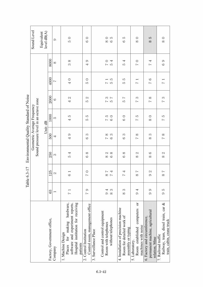
The result of noise measurement under usual stable operation is shown in Table 6.3-15 to 6.3-16, and the Mongolian environmental standard is shown in Table 6.3-17.
The noise standard concerning the plant is 85 dB (A), and since the noise level of the circumference under usual operation was in the range of the standard value, it is considered that there is almost no influence on the periphery.
2) Unsteady Noise (Noise occurring by emitting steam from a safety valve)
When the safety valves release the steam in order to perform pressure adjustment between boilers, a loud noise with sharp, high frequency occurs occasionally.
A complaint has been made from residents within the circumference regarding this noise. Moreover, although the Ministry for Nature & the Environment has advised the improvement of this situation, TES4 has replied that it is technically impossible.
The result measured in the periphery on September 5, 2001 is shown in Table 6.3-18.
The sound level at seven points located at a distance of about 550 to 1,440 m from the safety valve of boiler unit No.3 was in the range of 81 to 96 dB(A) and the noise value of several measurement points exceeded the standard of 85 dB(A).
As for this unsteady noise from the safety valve, it is considered that measures such as installing silencers, etc. are required.
In addition, the sound source level at the time of steam discharge is about 140~150 dB (A) according to the calculation result by the following formula:
L1 - L2 = 20 log r2/r1
L1: Sound pressure level at r1 (m) L2: Sound pressure level at r2 (m) r1: Distance from sound source r2: Distance from sound source
6.3-38
(3) Waste Water
All the waste water excepting sewage is fed to the slurry pit at TES4. The waste water is pressured up to the 3rd ash disposal pond and the amount is about 2,000 t/h. This pond is located on the west side of about 4 km from the power station and the circumference of the pond is about 2 km. The ash is settled in the pond and the surface water is sent back to the power station for recycling without being discharged outside.
Although this system has not a waste water treatment facility, it is conceivable that there is no influence on the periphery, unless the wastewater is discharged outside.
In addition, the sewage from the household of TES4 is discharged to the city sewer.
Fig 6.3-9 shows the waste water flow and Table 6.3-19 shows analysis data of circulation water and make up water (well water).
6.3-39
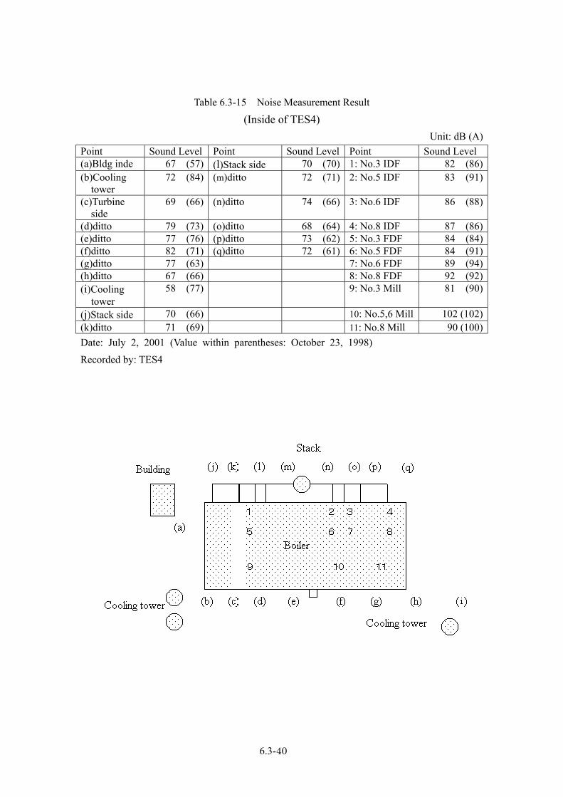
Table 6.3-15 Noise Measurement Result
(Inside of TES4) Unit: dB (A)
Point Sound Level Point Sound Level Point Sound Level (a)Bldg inde 67 (57) (l)Stack side 70 (70) 1: No.3 IDF 82 (86) (b)Cooling tower
72 (84) (m)ditto 72 (71) 2: No.5 IDF 83 (91)
(c)Turbine side
69 (66) (n)ditto 74 (66) 3: No.6 IDF 86 (88)
(d)ditto 79 (73) (o)ditto 68 (64) 4: No.8 IDF 87 (86) (e)ditto 77 (76) (p)ditto 73 (62) 5: No.3 FDF 84 (84) (f)ditto 82 (71) (q)ditto 72 (61) 6: No.5 FDF 84 (91) (g)ditto 77 (63) 7: No.6 FDF 89 (94) (h)ditto 67 (66) 8: No.8 FDF 92 (92) (i)Cooling tower
58 (77) 9: No.3 Mill 81 (90)
(j)Stack side 70 (66) 10: No.5,6 Mill 102 (102) (k)ditto 71 (69) 11: No.8 Mill 90 (100) Date: July 2, 2001 (Value within parentheses: October 23, 1998) Recorded by: TES4
6.3-40
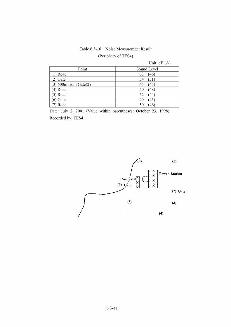
Table 6.3-16 Noise Measurement Result
(Periphery of TES4) Unit: dB (A)
Point Sound Level (1) Road 63 (46) (2) Gate 54 (51) (3) 600m from Gate(2) 45 (45) (4) Road 50 (48) (5) Road 52 (44) (6) Gate 49 (45) (7) Road 50 (46)
Date: July 2, 2001 (Value within parentheses: October 23, 1998) Recorded by: TES4
6.3-41
Tabl
e 6.
3-17
En
viro
nmen
tal Q
ualit
y St
anda
rd o
f Noi
se
Geo
met
ric A
vera
ge F
requ
ency
So
und
pres
sure
leve
l in
an o
ctav
e zo
ne
U
nit:
dB
63
125
250
500
1000
2000
4000
8000
Soun
d Le
vel
Eq
uiva
lent
le
vel d
B(A
)
Fact
ory,
Gov
ernm
ent o
ffic
e,
Com
pany
1
2
3
4
5
6
7
8
9
1. M
achi
ne D
esig
n
Plac
es
for
mak
ing
hard
war
e,
softw
are
and
expe
rimen
t re
ports
. H
ospi
tal
inst
itutio
n fo
r re
ceiv
ing
patie
nts
71
61
54
49
45
42
40
38
50
2. C
ontro
l Ins
titut
ion
Con
trol r
oom
, man
agem
ent o
ffice
79
70
68
63
55
52
50
49
60
3.
Sur
veill
ance
Pla
ce
C
ontro
l and
con
trol e
quip
men
t R
oom
with
tele
phon
es
with
out t
elep
hone
s
94
83
87
74
82
68
78
63
75
60
73
57
71
55
70
54
80
65
4. In
stal
latio
n of
pre
cisi
on m
achi
ne
Roo
m fo
r det
aile
d w
ork
of
asse
mbl
y or
typi
ng
83
74
68
63
60
57
55
54
65
5. L
abor
ator
y.
Roo
m
esta
blis
hed
com
pute
rs
or
mac
hine
s with
noi
se
94
87
82
78
75
73
71
70
80
6. F
acto
ry a
nd c
ircum
fere
nce,
pe
rman
ent m
achi
ne, a
gric
ultu
ral
rela
tion,
Min
e 99
92
86
83
80
78
76
74
8
5
7. R
ailro
ad tr
affic
R
ailw
ay, t
ram
, die
sel t
rain
, car
&
train
, cab
in, c
rane
truc
k 95
87
82
78
75
73
71
69
80
6.3-42
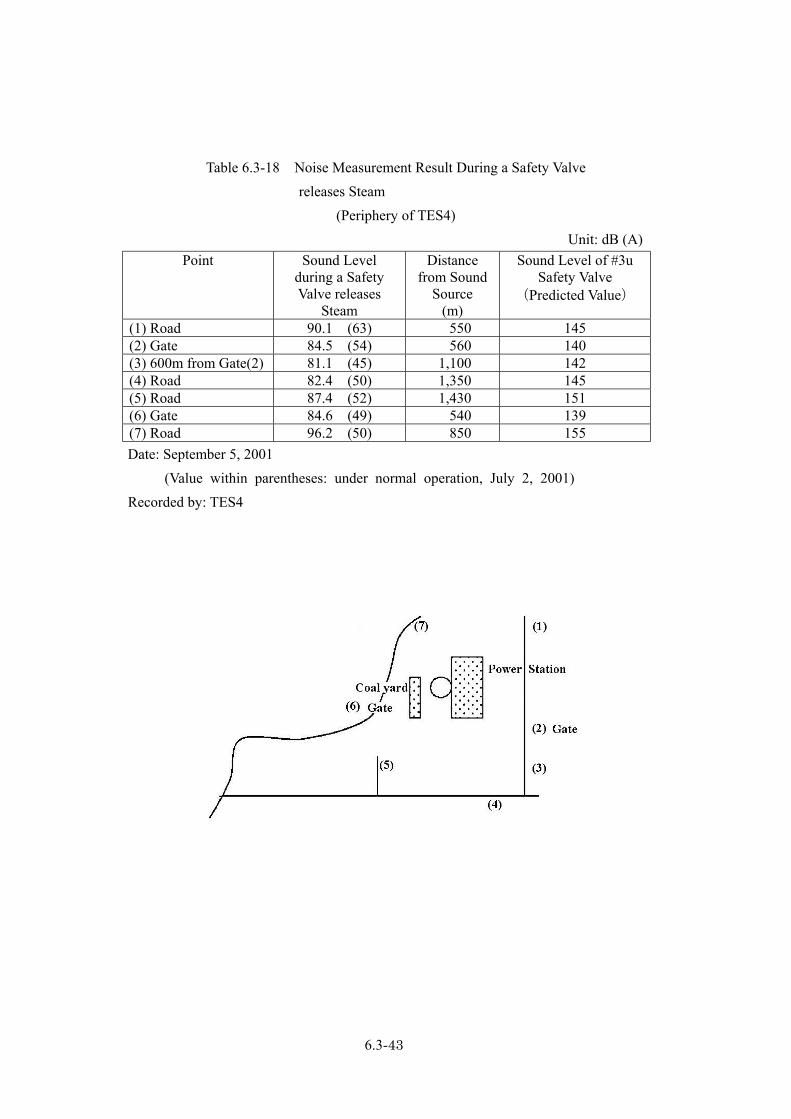
Table 6.3-18 Noise Measurement Result During a Safety Valve
releases Steam (Periphery of TES4)
Unit: dB (A) Point Sound Level
during a Safety Valve releases
Steam
Distance from Sound
Source (m)
Sound Level of #3u Safety Valve
(Predicted Value)
(1) Road 90.1 (63) 550 145 (2) Gate 84.5 (54) 560 140 (3) 600m from Gate(2) 81.1 (45) 1,100 142 (4) Road 82.4 (50) 1,350 145 (5) Road 87.4 (52) 1,430 151 (6) Gate 84.6 (49) 540 139 (7) Road 96.2 (50) 850 155
Date: September 5, 2001 (Value within parentheses: under normal operation, July 2, 2001) Recorded by: TES4
6.3-43
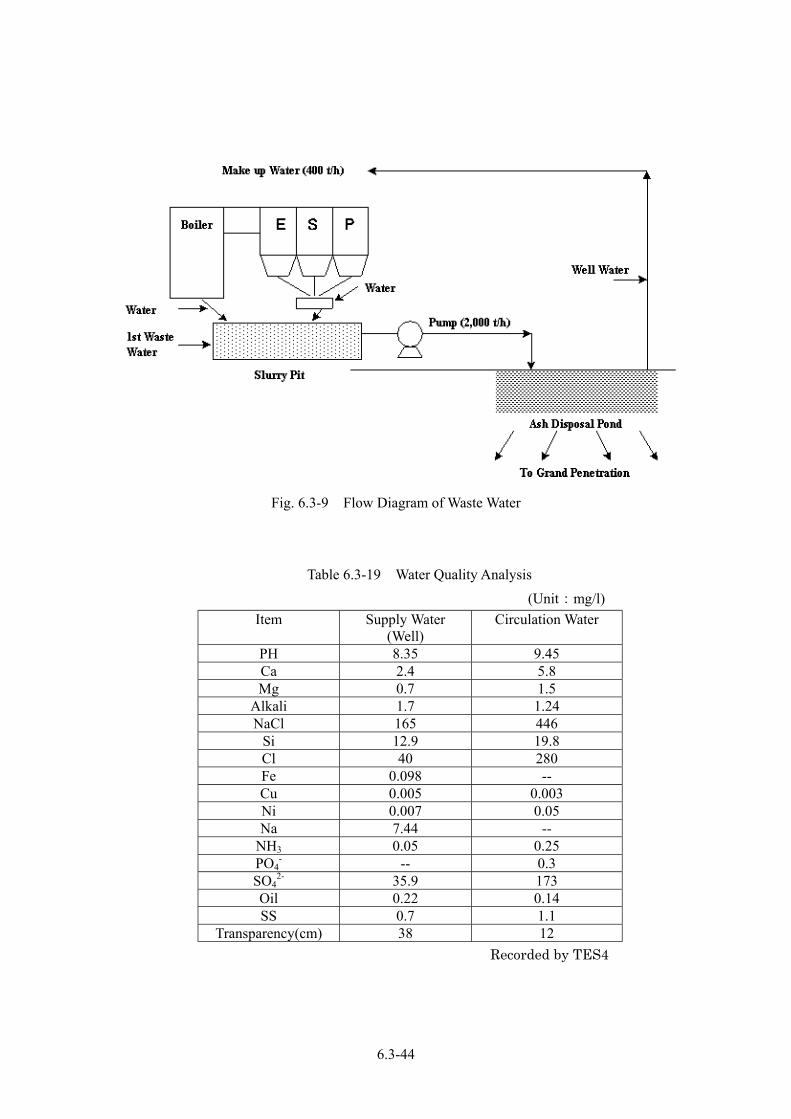
Fig. 6.3-9 Flow Diagram of Waste Water
Table 6.3-19 Water Quality Analysis
(Unit:mg/l) Item Supply Water
(Well) Circulation Water
PH 8.35 9.45 Ca 2.4 5.8 Mg 0.7 1.5
Alkali 1.7 1.24 NaCl 165 446
Si 12.9 19.8 Cl 40 280 Fe 0.098 -- Cu 0.005 0.003 Ni 0.007 0.05 Na 7.44 --
NH3 0.05 0.25 PO4
- -- 0.3 SO4
2- 35.9 173 Oil 0.22 0.14 SS 0.7 1.1
Transparency(cm) 38 12 Recorded by TES4
6.3-44
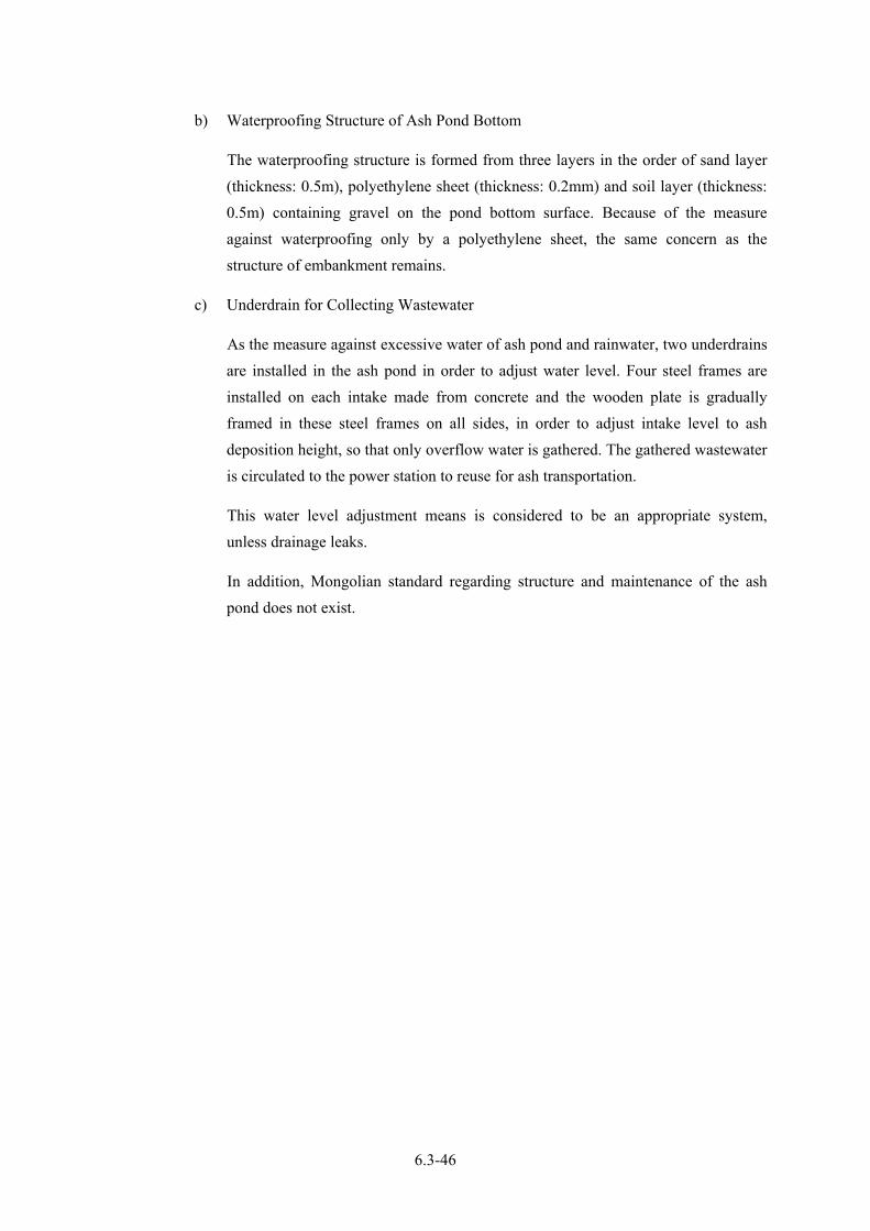
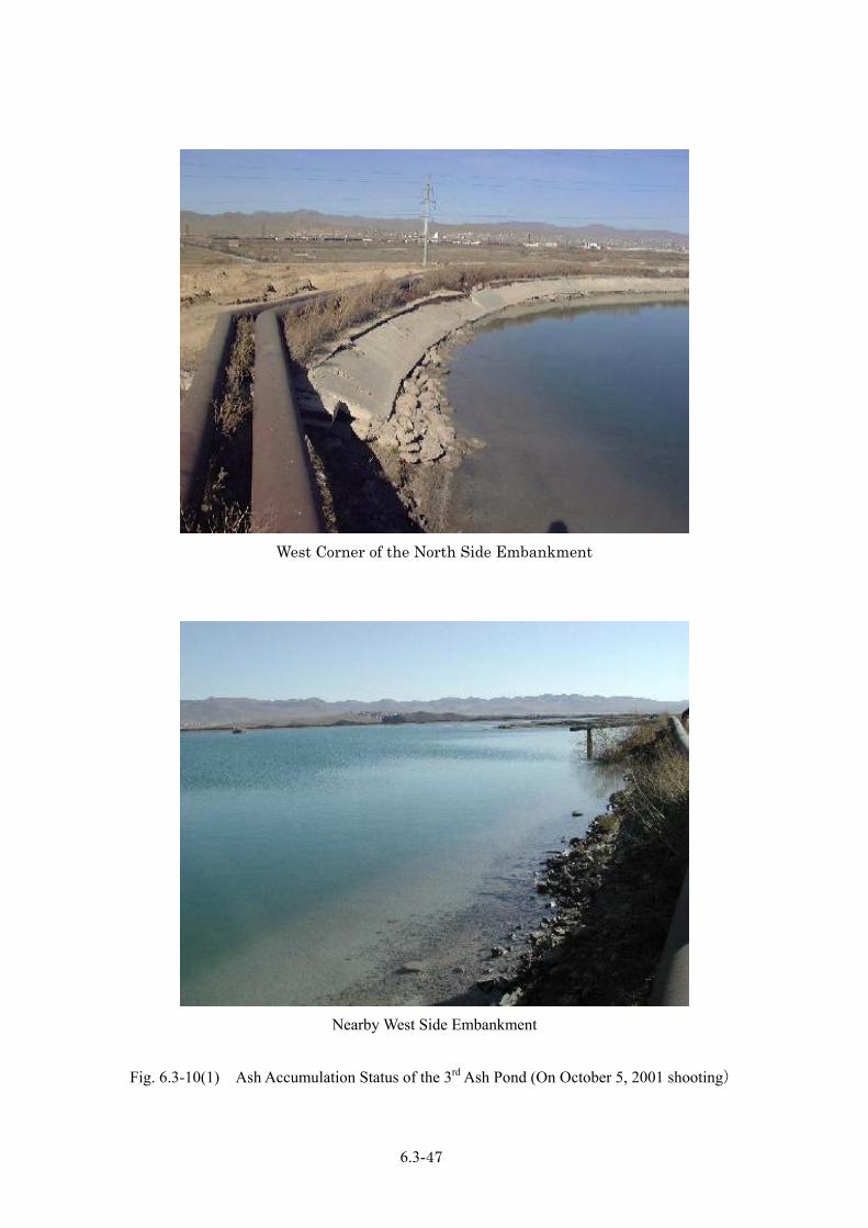
(4) Situation of the 3rd Ash Disposal Pond
The ash disposal pond was constructed in 1983 based on Russian design. During the operation period, the pond was divided to two small sections and the ash reclamation started in first section. At present, the 2nd section is under reclamation. This section is the 3rd ash pond with a volume of 1,961,000m3 and has been under reclamation since 1995.
In addition, since groundwater existed under the ash pond, digging of the soil was omitted during the construction. Figure 6.3-10 shows the status of ash reclamation in the 3rd ash pond.
1) Scale and Structure of the 3rd Ash Pond
The structure of the 3rd ash pond is shown in Fig. 6.3-11 and Fig. 6.3-12.
(a) Scale of Ash Pond
- Reclamation area: 280,870 m2 (about 553 m x 552 m)
- Reclamation capacity: 1,961,000 m3
(b) Structure of Ash Pond
a) Structure of Embankment
The embankment of the 3rd ash pond is developed with earth and sand (sand and gravel) carried from a point 40 km away (Height of embankment: about 8.5 m, upper width: about 6 m, bottom width: about 50 m).
As a result of an examination on embankment stability based on the physical property values of the raw material, the embankment design is considered to be adequate. (Refer to Table 6.3-20).
The waterproof structure is formed from 4 layers in the order of a sand layer (thickness: 0.3 m), polyethylene sheet (Russian product, thickness: 0.2 mm), sand layer (thickness: 0.5 m) and a soil layer (thickness: 0.2 m) containing gravel on the embankment ground surface.
Therefore, it is not an overstatement to say that prevention against exudation is carried out only by use of a polyethylene sheet with a thickness of 0.2 mm.
Although there is no actual result of waste waster disclosure in the 1st and 2nd ash pond with the same structure according to TES4, the intensity of the sheet and a waterproof problem are apprehended in comparison with Japanese standard of ash pond structure.
6.3-45
b) Waterproofing Structure of Ash Pond Bottom
The waterproofing structure is formed from three layers in the order of sand layer (thickness: 0.5m), polyethylene sheet (thickness: 0.2mm) and soil layer (thickness: 0.5m) containing gravel on the pond bottom surface. Because of the measure against waterproofing only by a polyethylene sheet, the same concern as the structure of embankment remains.
c) Underdrain for Collecting Wastewater
As the measure against excessive water of ash pond and rainwater, two underdrains are installed in the ash pond in order to adjust water level. Four steel frames are installed on each intake made from concrete and the wooden plate is gradually framed in these steel frames on all sides, in order to adjust intake level to ash deposition height, so that only overflow water is gathered. The gathered wastewater is circulated to the power station to reuse for ash transportation.
This water level adjustment means is considered to be an appropriate system, unless drainage leaks.
In addition, Mongolian standard regarding structure and maintenance of the ash pond does not exist.
6.3-46
West Corner of the North Side Embankment
Nearby West Side Embankment
Fig. 6.3-10(1) Ash Accumulation Status of the 3rd Ash Pond (On October 5, 2001 shooting)
6.3-47
Nearby South Side Embankment
Nearby South Side Embankment
Fig. 6.3-10(2) Ash Accumulation Status of the 3rd Ash Pond (On October 5, 2001 shooting)
6.3-49

カラーの裏
6.3-50


![ϴɵpz M Í w ] J r>b - JICA](https://img.pdfslide.us/doc/110x75/61ef20b8a126ba398c2e5c08/pz-m-w-j-rgtb-jica.jpg)