Embed Size (px)
Citation preview

L-STAT L-STAT™ Network Thermostat
User Manual
LOYTEC electronics GmbH

Contact
LOYTEC electronics GmbH
Blumengasse 35
1170 Vienna
AUSTRIA/EUROPE
http://www.loytec.com
Version 1.4
Document 88085805
LOYTEC MAKES AND YOU RECEIVE NO WARRANTIES OR CONDITIONS,
EXPRESS, IMPLIED, STATUTORY OR IN ANY COMMUNICATION WITH YOU,
AND
LOYTEC SPECIFICALLY DISCLAIMS ANY IMPLIED WARRANTY OF
MERCHANTABILITY OR FITNESS FOR A PARTICULAR PURPOSE. THIS
PRODUCT IS NOT DESIGNED OR INTENDED FOR USE IN EQUIPMENT
INTENDED FOR SURGICAL IMPLANT INTO THE BODY OR OTHER
APPLICATIONS INTENDED TO SUPPORT OR SUSTAIN LIFE, FOR USE IN
FLIGHT CONTROL OR ENGINE CONTROL EQUIPMENT WITHIN AN
AIRCRAFT, OR FOR ANY OTHER APPLICATION IN WHICH IN THE FAILURE
OF SUCH PRODUCT COULD CREATE A SITUATION IN WHICH PERSONAL
INJURY OR DEATH MAY OCCUR. LOYTEC MAKES NO REPRESENTATION
AND OFFERS NO WARRANTY OF ANY KIND REGARDING OF ANY
THIRDPARTY COMPONENTS MENTIONED IN THIS MANUAL.
No part of this publication may be reproduced, stored in a retrieval system, or transmitted, in
any form or by any means, electronic, mechanical, photocopying, recording, or otherwise,
without the prior written permission of LOYTEC.
LC3020, L-Chip, L-Core, L-DALI, L-GATE, L-INX, L-IOB,
LIOB-Connect, LIOB-FT, L-IP, LPA, L-Proxy, L-Switch, L-Term,
L-VIS, L-WEB, L-ZIBI, ORION™ stack and Smart Auto-Connect™ are
trademarks of LOYTEC electronics GmbH.

L-STAT User Manual 3 LOYTEC
Version 1.4 LOYTEC electronics GmbH
Contents
1 Introduction .................................................................................................. 7
1.1 Overview .............................................................................................................. 7
1.2 Key Features ........................................................................................................ 8
1.3 LCD Segments ..................................................................................................... 9
2 What´s New in L-STAT ............................................................................. 13
2.1 New in L-STAT 1.4.0 ........................................................................................ 13
2.2 New in L-STAT 1.2.3 ........................................................................................ 13
2.3 New in L-STAT 1.2.0 ........................................................................................ 13
2.4 New in L-STAT 1.1.0 ........................................................................................ 14
3 Quick-Start Guide ...................................................................................... 15
3.1 Hardware Installation ....................................................................................... 15
3.2 User Interface .................................................................................................... 16
3.2.1 General Description .................................................................................. 16
3.2.2 Operating Modes ...................................................................................... 17
3.2.3 Access Levels ........................................................................................... 19
3.2.4 Device Settings......................................................................................... 20
3.2.5 Factory Default ......................................................................................... 21
3.3 Getting Started with the Configurator ............................................................ 22
4 Modbus ........................................................................................................ 23
4.1 Introduction ....................................................................................................... 23
4.2 Modbus Network ............................................................................................... 23
4.3 Modbus Register Usage for Value Display ..................................................... 24
4.4 Modbus Register Description ........................................................................... 25
4.4.1 Data Registers .......................................................................................... 25
4.4.2 Device Settings......................................................................................... 33
4.4.3 Configuration Registers ............................................................................ 36
4.4.4 Model Information Registers (read only) .................................................. 52
4.4.5 Device Information Registers (read only) ................................................. 54
4.4.6 NFC Registers .......................................................................................... 55
4.4.7 Value Scaling and Stepwidth ................................................................... 56
5 NFC .............................................................................................................. 57
5.1 General Description .......................................................................................... 57
5.2 Copy the L-WEB Project URL to the NFC Tag Memory ............................. 58
6 IR-Remote Control Operation .................................................................. 60
6.1 General Description .......................................................................................... 60

L-STAT User Manual 4 LOYTEC
Version 1.4 LOYTEC electronics GmbH
6.2 Remote Control Pairing ................................................................................... 61
7 Firmware Update ....................................................................................... 62
7.1 Firmware Update via the Web Interface ........................................................ 62
7.2 Restoring Default Modbus Settings in Bootloader ......................................... 63
8 Configuration Backup & Restore ............................................................. 64
8.1 Configuration Backup & Restore via the Web Interface .............................. 64
9 Troubleshooting .......................................................................................... 65
9.1 Technical Support ............................................................................................. 65
10 Specifications .............................................................................................. 66
10.1 Physical Specifications ...................................................................................... 66
10.2 Sensor Specifications ........................................................................................ 68
11 References ................................................................................................... 70
12 Revision History ......................................................................................... 71

L-STAT User Manual 5 LOYTEC
Version 1.4 LOYTEC electronics GmbH
Abbreviations
ASCII .................................. American Standard Code for Information Interchange
IR ........................................ Infrared
LCD .................................... Liquid Crystal Display
NDEF .................................. NFC Data Exchange Format
NFC ..................................... Near Field Communication
RGB .................................... Red, Green, Blue
URI ...................................... Uniform Resource Identifier
URL .................................... Uniform Resource Locator


L-STAT User Manual 7 LOYTEC
Version 1.4 LOYTEC electronics GmbH
1 Introduction
1.1 Overview
The L-STAT is a network thermostat device with a modern, minimalistic look that fits any
interior design. It is directly connected to a LOYTEC controller with a Modbus interface
such as LIOB-AIR, L-ROC or L-INX.
Up to 16 L-STAT devices can be connected to one controller to offer control at different
locations for the largest rooms. The L-STAT is equipped with a segmented LCD display
featuring an RGB backlight with adjustable color, offering a neat way to make the L-STAT
match the interior color concept of an office building. Eight capacitive touch buttons are
used to cycle through sensor values, display parameters, and adjust setpoints. Up to four
external buttons can be accessed and processed by the controller.
The L-STAT’s internal sensors measure temperature, humidity, dew point, occupancy and
CO2 level. Sensor values can be displayed in SI or US units. Additionally, the date and time
as well as the current level of eco-friendliness are also displayed on the LCD display.
Parameters controlled by the controller’s logic can be overridden on the L-STAT, such as for
occupancy, air conditioning, and ventilation. A direct access mode is available to quickly
adjust the most important setpoints e.g. for temperature and ventilation control.
A buzzer provides acoustic feedback for the touch buttons and can also be used to indicate
alarms and error states. To prevent unauthorized modifications, two access levels (end user,
system integrator) are used, which are secured via 4-digit pin codes. Device replacement,
firmware upgrade, and L-STAT configuration are performed with very little effort through
the controller. The L-STAT device is represented in the controller by a simple data point
interface, which can be directly connected to the IEC 61131 or IEC 61499 logic application
and offers all common functions for data points such as alarming, scheduling, trending,
historic filters, math functions, etc.
Using an NFC tag, the L-STAT transmits the URL of an L-WEB project to mobile devices
for more extensive control and administrative tasks. Last but not least, the L-STAT comes
with a built-in infrared receiver for comfortable remote control.

L-STAT User Manual 8 LOYTEC
Version 1.4 LOYTEC electronics GmbH
1.2 Key Features
The different L-STAT models and their features are documented in Table 1.
Features LSTAT-800-Gx-Lx LSTAT-801-Gx-Lx LSTAT-802-Gx-Lx
Modbus RTU Slave
NFC Tag
Buzzer
Internal
Temperature Sensor
Internal Relative
Humidity Sensor
3 x Digital Inputs
1 x Analog Input
Infrared Receiver
Occupancy Sensor -
CO2 Sensor - -
Table 1: Key Features
Not only the model type but also the enclosure color as well as the touch button layout is
defined with the order code. See Table 2 for possible order codes.
Nomenclature of Order Codes
Model Type 80x: 800, 801, 802 (see Table 1)
Enclosure Gx: G1 – silver
G2 – black
G3 – white
Layout Lx: L1 –
L2 –
L3 –
L4 –
L5 –
L6 –
Table 2: Possible Order Codes

L-STAT User Manual 9 LOYTEC
Version 1.4 LOYTEC electronics GmbH
1.3 LCD Segments
The following Figure 1 shows the LCD of the L-STAT with all possible segments.
Figure 1: LCD Segments available on L-STAT
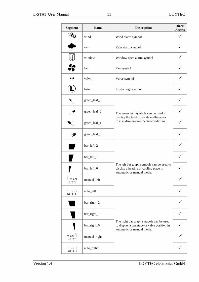
The following Table gives an overview of all available segments of the L-STAT LCD with
its defined names. The Table also shows which symbols are directly accessible via Modbus
registers (see Table 12 on Page 29).
Segment Name Description Direct
Access
heat Heating symbol
alarm_bell Alarm bell symbol
drop Drop symbol
drop_not Cross out for drop symbol
alarm Alarm symbol
light Light bulb symbol
blinds Sun blinds symbol

L-STAT User Manual 10 LOYTEC
Version 1.4 LOYTEC electronics GmbH
Segment Name Description Direct
Access
clock Clock symbol
sun_left Left half of sun symbol
sun_right Right half of sun symbol
moon Moon symbol
colon
The colon symbol of the secondary
display will only be available if the
secondary_display_direct_access_string
register at address 200 (see Table 23 Page
37) is not empty.
secondary_display
The secondary display is used to show
time, date and/or a short text depending
on the semantic meaning of a display
value or set point. It can also be directly
accessed via the Modbus register:
secondary_display_direct_access_string
(see Table 23 on Page 37).
am_pm_symbols
These symbols are not directly accessible
but are shown along with the time when
12h time format has been selected. -
cool Cooling symbol
man_out Man outside the house (no occupancy)
man_in Man inside the house (occupancy)
arrow Arrow symbol (to represent a set point)
temp_in Temperature inside
temp_out Tempareture outside
house House symbol
text_symbols
The text symbols are not accessible via
Modbus but are shown at certain modes
or events.
-
key
The key symbol is primarily used to show
that a set point is pincode protected but it
can also be accessed via the symbol direct
access registers.
L-STAT User Manual 11 LOYTEC
Version 1.4 LOYTEC electronics GmbH
Segment Name Description Direct
Access
wind Wind alarm symbol
rain Rain alarm symbol
window Window open alarm symbol
fan Fan symbol
valve Valve symbol
logo Loytec logo symbol
green_leaf_3
The green leaf symbols can be used to
display the level of eco-friendliness or
to visualize environmental conditions.
green_leaf_2
green_leaf_1
green_leaf_0
bar_left_2
The left bar graph symbols can be used to
display a heating or cooling stage in
automatic or manual mode.
bar_left_1
bar_left_0
manual_left
auto_left
bar_right_2
The right bar graph symbols can be used
to display a fan stage or valve position in
automatic or manual mode.
bar_right_1
bar_right_0
manual_right
auto_right

L-STAT User Manual 12 LOYTEC
Version 1.4 LOYTEC electronics GmbH
Segment Name Description Direct
Access
main_display
The main display is primarily used to
show certain values. It is not accessible
directly. -
unit_F
All unit symbols are not directly
accessible but are displayed along with a
display value or set point if the unit is set
in the corresponding configuration
register.
See Table 28 on Page 42 for display
value configuration
and Table 29 on Page 44 for set point
configuration.
-
unit_C -
unit_cfm -
unit_l/s -
unit_m³/h -
unit_Pa -
unit_inWC -
unit_V -
unit_% -
unit_%RH -
unit_ppm -
Table 3: LCD Segments Overview

L-STAT User Manual 13 LOYTEC
Version 1.4 LOYTEC electronics GmbH
2 What´s New in L-STAT
2.1 New in L-STAT 1.4.0
This section describes the major changes and new features. For a full list of changes refer to
the Readme file.
Loading Factory Default Values in Device Settings Menu
Factory default values can now be loaded via the device settings menu. For further
information see Section 3.2.5 on Page 21.
2.2 New in L-STAT 1.2.3
This section describes the major changes and new features. For a full list of changes refer to
the Readme file.
Display Auto Shuffle Mode
At the user_interface_settings register at address 183 (see Table 20 on Page 35) the DAS
flag was added which activates the display auto shuffle mode, where each display value or
set point is shown for 5 seconds within a cycle.
2.3 New in L-STAT 1.2.0
This section describes the major changes and new features. For a full list of changes refer to
the Readme file.
Configuration Backup & Restore
The new firmware supports the backup and restore of Modbus registers used for configuring
the device. Please see Chapter 8 for further information.
Secondary_display_direct_access_string_volatile Flag
An additional flag was added at the configuration flags register at address 192 (see Table 22
on Page 36) for setting the content of the secondary_display_direct_access_string register
volatile.

L-STAT User Manual 14 LOYTEC
Version 1.4 LOYTEC electronics GmbH
2.4 New in L-STAT 1.1.0
This section describes the major changes and new features. For a full list of changes refer to
the Readme file.
Cleaning Function
This is a special mode for cleaning the surface of the device where touch-buttons are
disabled for a certain amount of time. Please see Section 3.2.2 for further information.
External Button Inputs support Switches
With this firmware the external button inputs are supporting push-buttons and switches too.

L-STAT User Manual 15 LOYTEC
Version 1.4 LOYTEC electronics GmbH
3 Quick-Start Guide
3.1 Hardware Installation
Please refer to the L-STAT installation sheet for further information on dimensions,
mounting and wiring.
Figure 2 shows the back view of the device with the connection terminals for Modbus, 24 V
DC-Supply and external buttons. The four external buttons share a common GND
connection which is internally connected to the negative 24 V input terminal.
The external button terminal EB3 is also capable of sensing a NTC-10k temperature sensor.
The temperature value of the sensor will be provided on Modbus register address 49 (see
Table 10 on Page 27). The cable length for connecting the temperature sensor must not
exceed 150m for 0.5mm² or 70m for 0.25mm² to guarantee a temperature error less than
0.1% at 25°C.
Figure 2: Back View LSTAT-80x-Gx-Lx

L-STAT User Manual 16 LOYTEC
Version 1.4 LOYTEC electronics GmbH
3.2 User Interface
3.2.1 General Description
The user interface consists of the LCD for displaying any desired value and up to eight
touch buttons which are used to adjust set points and change settings. Additionally up to
four external push-buttons can be connected to the device.
Figure 3: Front View LSTAT-80x-Gx-Lx
Each button can be configured individually via a Modbus register for its function (see Table
24 on Page 38). The following listing gives you an overview which functionality can be
associated with the buttons.
UP DOWN
change set point or device setting in EDIT-mode
directly access a set point in DISPLAY-mode
ON OFF
no specific function, the button state can be requested to control lighting
OCCUPANCY
no specific function, the button state can be requested to set occupancy
state
MENU
short press <3s: cycle through display values, set points or device
settings
long press ~3s: switch between DISPLAY-mode and EDIT-mode
long press >6s: switch to CLEANING-mode
TB0 TB1 TB2 TB3
TB4 TB5 TB6 TB7
LCD
Touch Buttons

L-STAT User Manual 17 LOYTEC
Version 1.4 LOYTEC electronics GmbH
3.2.2 Operating Modes
In Figure 4 the operating modes of L-STAT are depicted. Each operating mode gives access
to certain Modbus registers that can either be viewed or edited depending on the mode. The
following data is available on L-STAT:
display values: Are used to visualize data provided by the Modbus master or values
of internal sensors. It is viewed in DISPLAY-mode. For the display
value registers see Table 11 on Page 28 and Table 28 on Page 42 for
the corresponding display value configuration.
set points: Are used to visualize data that is provided by the Modbus master and
that can be edited by the user. It is shown in DISPLAY-mode and it
can be edited in EDIT-mode. For the set point registers see Table 32
on Page 48 and Table 29 on Page 44 for set point configuration.
The range in which a set point can be altered is defined by minimum
and maximum values that have to be written by the Modbus master.
Please refer to Table 33 on Page 49 and Table 34 on Page 50.
device settings: These values define some basic settings of the device itself. Please
refer to Table 5 on Page 20 for a listing of all device settings and to
Table 18, Table 19 and Table 20 on Page 33 f. for the corresponding
Modbus registers. Device Settings can only be edited by the system
administrator in EDIT-mode.
offset values: Are used to add a certain offset to a display value. This functionality
can be used to calibrate sensor values. Offset values can be editet by
the system administrator in CALIBRATION-mode directly at the
device or over Modbus. Please see Table 35 on Page 51 for the offset
value register.
Figure 4: Operating Modes of L-STAT
When the device powers up, it enters DISPLAY-mode and it will display the first display
value. When pressing the MENU-button the next value will be shown. First all active display
values and then all active set points are displayed. After the last set point, the display will
show the first display value again.
EDIT-mode is entered by pressing the MENU-button for more than 3 seconds. To enter
EDIT-mode as system administrator two additionally defined buttons (TB0 and TB4) need
to be pressed along with the MENU-button for more than 3 seconds. Also in EDIT-Mode a
short press on the MENU-button is used to go to the next value. Any other button that has
no specific function can be used in EDIT-mode to cycle the values in the opposite direction.
EDIT-mode is left when pressing the MENU-button for more than 3 second.
The system administrator will also be able to view and edit the device settings.

L-STAT User Manual 18 LOYTEC
Version 1.4 LOYTEC electronics GmbH
CALIBRATION-mode will be entered for any display value when pressing one UP- and one
DOWN-button simultaneously for more than 3 seconds to adjust the offset. This mode is
secured by the system administrator password. CALIBRATION-mode is left when pressing
the MENU-button for more than 3 second or after a timeout of 1 minute.
An overview of all possible operating modes is given in Table 4 below. The operating mode
can also be defined by the Modbus master by writing the user interface direct access register
(see Table 13 on Page 29).
Order of L-STAT Operating Modes Description
0 DISPLAY-mode / display values Display values are shown.
1 DISPLAY-mode / set points Set points are shown.
2 EDIT-mode / set points Set points can be edited.
3 EDIT-mode / device settings
Device settings can be edited. This mode
is only accessible for the system admi-
nistrator.
4 CALIBRATION-mode / offset values Offset values can be edited
5 PINCODE-ENTRY / end user
The pincode for the end user has to be
entered to show and/or edit the requested
value.
6 PINCODE-ENTRY / system administrator
The pincode for the system administator
has to be entered to show and/or edit the
requested value.
7 DIRECT_ACCESS-mode / set points
A defined set point can be accessed and
edited without entering EDIT-mode. It
can be entered by pressing a defined
button (see Table 24 on Page 38). In
contrast to EDIT-mode only predefined
set points can be edited.
The DIRECT_ACCESS-mode can be
left by pressing any button that has no
direct access capability.
10 CLEANING-mode
This mode is used to clean the surface of
the device without any response of the
touch buttons and hence any unwanted
changes. This mode is entered by
pressing the MENU-button for at least 6
seconds. After 10 seconds with no
interaction the device will switch back to
DISPLAY-mode automatically.
Table 4: Operating Modes

L-STAT User Manual 19 LOYTEC
Version 1.4 LOYTEC electronics GmbH
3.2.3 Access Levels
The L-STAT has two access levels (end user & system administrator) with configurable
rights to display and edit values. Each access level is secured by a four digit pincode that
will be requested if EDIT-mode or DIRECT_ACCESS-mode is entered and the desired
value is pincode protected.
Per default the pincode for end user and system administrator access level is disabled
(0000). Otherwise the pincode can be entered as described in Figure 5.
Figure 5: Pincode Entry

L-STAT User Manual 20 LOYTEC
Version 1.4 LOYTEC electronics GmbH
3.2.4 Device Settings
The following Table gives an overview of the device settings accessible through the button
interface as well as via Modbus. For the corresponding Modbus registers please refere to
Table 18, Table 19 and Table 20 on Page 33 and following.
Device Setting Possible Values Default Your Setting
Modbus Parity Odd / Even / None None
Modbus Baudrate 1.2kB / 2.4kB / 4.8kB / 9.6kB /
19.2kB / 38.4kB / 57.6kB / 115.2kB 57,6kB
Modbus Address 1 - 247 1
Pincode System
Administrator
0000 – 9999
(if 0000 the pincode is disabled) 0000
Pincode End User 0000 – 9999
(if 0000 the pincode is disabled) 0000
Color Setting LCD
Backlight Red 0% - 100% 100%
Color Setting LCD
Backlight Green 0% - 100% 100%
Color Setting LCD
Backlight Blue 0% - 100% 100%
Brightness LCD
Backlight 0% - 100% 100%
LCD Contrast 0% - 100% 100%
LCD Color Scheme
0 – user (as defined above)
1 – white
2 – red
3 – green
4 – blue
5 – orange
6 – magenta
7 – cyan
0
Time Format 24h / 12h 24h
Show Date on / off off
Show Time on / off off
Acoustic Feedback (for
Touch Buttons) on / off on
Goto First Display Value
(the first display value
will be displayed after 1
minute without inter-
action)
on / off on
Display Auto Shuffle on / off off
Display Auto Dim
(lcd brightness will be
dimmed after 2 minutes
with no interaction)
off / 50% / 10% / 0% / OCC*
* built-in occupancy sensor
activates display
off
Unit System SI / US SI
Device Restart off – if a DOWN-button is pressed
the device will be rebooted manually -
Load Factory Defaults see Section 3.2.5 on Page 21 -
Table 5: Device Settings

L-STAT User Manual 21 LOYTEC
Version 1.4 LOYTEC electronics GmbH
3.2.5 Factory Default
The factory default configuration for display values and set points depends on the specific
L-STAT model. The following Table shows the factory default values for each model. See
Table 28 on Page 42 for display value configuration and Table 29 on Page 44 for set point
configuration.
LSTAT-800-Gx-Lx LSTAT-801-Gx-Lx LSTAT-802-Gx-Lx
display_value_0 Internal Temperature Internal Temperature Internal Temperature
display_value_1 Relative Humidity Relative Humidity Relative Humidity
display_value_2 Dew Point Dew Point Dew Point
display_value_3 - - CO2 Level
display_value_4 Modbus Voltage Modbus Voltage Modbus Voltage
display_value_5 External Temperature External Temperature External Temperature
display_value_6
to
display_value_15 - - -
set_point_0 Internal Temperature
Set Point
Internal Temperature
Set Point
Internal Temperature
Set Point
set_point_1 Fan Stage Fan Stage Fan Stage
set_point_2
to
set_point_15 - - -
Table 6: Factory Default for L-STAT Models
The factory default values can be loaded manually via the device settings menu. The
function is located at the last position of the menu. The secondary display will show which
button has to be pressed as depicted in Figure 6. After all buttons have been pressed in the
right order the factory defaults will be loaded. Therefore the device will reboot. By pressing
the MENU button instead of UP or DOWN during the sequence the process can be aborted.
Figure 6: Loading the factory default values

L-STAT User Manual 22 LOYTEC
Version 1.4 LOYTEC electronics GmbH
3.3 Getting Started with the Configurator
A Modbus Template for the L-INX configurator with all available datapoints can be
downloaded from the Libraries/Templates Download section on the LOYTEC website:
https://www.loytec.com/support/download
For further information on using the L-INX configurator for Modbus devices please refer to
the L-INX Configurator User Manual [1].
Please refer to Chapter 4 for a listing of all available Modbus Registers.

L-STAT User Manual 23 LOYTEC
Version 1.4 LOYTEC electronics GmbH
4 Modbus
4.1 Introduction
The L-STAT operates as a Modbus slave in Modbus RTU mode. The default baudrate is set
to 57600, the default parity is set to ‘none’ and the default address is set to 1. The
communication with a Modbus master device will work with Modbus function code 0x03
(Read Holding Registers) and Modbus function code 0x06 (Preset Single Register). Section
4.4 shows all available Modbus registers.
4.2 Modbus Network
Figure 7 illustrates a typical Modbus network setup with a linear bus topology used to
connect several slave devices to a master device. The transmission line has to be terminated
at both ends. At the master device this can be done by connecting an L-Term (LT-04)
device. Each L-STAT slave device is equipped with a built-in 120Ω termination resistor. Set
the termination switch to OFF except on the last device on the bus where the termination
switch must be turned ON. Per default each device has the Modbus address set to 1.
Because each address can only be used once it has to be configured at the device settings in
EDIT-mode. For further information please see Section 3.2.
Figure 7: Modbus Network

L-STAT User Manual 24 LOYTEC
Version 1.4 LOYTEC electronics GmbH
4.3 Modbus Register Usage for Value Display
The following Figure 8 shows, which Modbus registers have influence on a displayed value,
unit, text on the secondary display or symbols. Depending on settings in configuration
registers different combinations are possible to achieve the desired result.
Figure 8: Modbus Register Usage for Value Display

L-STAT User Manual 25 LOYTEC
Version 1.4 LOYTEC electronics GmbH
4.4 Modbus Register Description
In the following sections the L-STAT Modbus registers are described. Abbrevations are
explained at the end of each table. ‘R’ indicates that this value is not used by now and that it
is reserved for future use. Square brackets ‘[]’ indicate that this is the initial value. Numbers
with the prefix ‘0x’ are hexadecimal values. Values with no prefix indicate decimal values.
4.4.1 Data Registers
These registers contain data that is changing frequently. This data is not stored persistent in
the L-STAT device and will be lost after a reboot.
Register Name Register
Address Bit Position
15 14 13 12 11 10 9 8 7 6 5 4 3 2 1 0
present_state 0
0x0000
R
[0]
R
[0]
R
[0]
Occu
[0]
EB
3 [
0]
EB
2 [
0]
EB
1 [
0]
EB
0 [
0]
TB
7 [
0]
TB
6 [
0]
TB
5 [
0]
TB
4 [
0]
TB
3 [
0]
TB
2 [
0]
TB
1 [
0]
TB
0 [
0]
short_pressed 1
0x0001
IRC
[0]
NFC
[0]
R
[0]
Occu
[0]
long_pressed 2
0x0002
FD
[1]
ERR
[0]
DOC
[0]
SPC
[0]
The present_state register always represents the actual state of the buttons and the
occupancy sensor.
The short_pressed and long_pressed states will remain set until the flags are cleared by the
Modbus master by writing a logical ‘1’ to the specific flag, except the occupancy flag that
is cleared automatically after the occupancy_timeout has expired. The long_pressed state
of a button will remain set as long as the button is pressed.
Bits 0-11 indicate the states of the buttons (TBx-touch button, EBx-external button)
Occu: occupancy flag, defines if occupancy is detected by built-in occupancy sensor
(applies to LSTAT-801-Gx-Lx and LSTAT-802-Gx-Lx)
NFC: NFC flag, is set if an NFC field was detected. This gives the information that a
user is reading the NFC tag memory with an NFC enabled mobile device. For
more information see Chapter 5.
IRC: infrared remote control flag, is set when an infrared remote control code was
received. The received code can be read via the ir_remote_control_command
register at register address 32 (see Table 9 on Page 27).
SPC: Set point changed flag, is set when a set point was changed on the L-STAT.
Each set point has an individual change flag at register address 3 (see Table 8 on
Page 26).
DOC: device setting or offset value changed flag, is set when a device setting or offset
value was changed on the L-STAT. The specific change flags can be read via the
registers at address 4 and 5 (see Table 8 on Page 26).
ERR: error flag, is set when an internal error has occurred.
FD: factory default (unconfigured) flag, is set when the device has booted with factory
default settings.
Button states and flags can have the following binary values:
1 – pressed, set
0 – released, cleared
The present_state register is only updated in DISPLAY- and DIRECT_ACCESS-mode!
(For a list of possible modes see Table 4 on Page 18)

L-STAT User Manual 26 LOYTEC
Version 1.4 LOYTEC electronics GmbH
Table 7: Button States and Flags
Register Name Register
Address Bit Position
15 14 13 12 11 10 9 8 7 6 5 4 3 2 1 0
change_flags_
set_points
3
0x0003
SP15
[0]
SP14
[0]
SP13
[0]
SP12
[0]
SP11
[0]
SP10
[0]
SP9
[0]
SP8
[0]
SP7
[0]
SP6
[0]
SP5
[0]
SP4
[0]
SP3
[0]
SP2
[0]
SP1
[0]
SP0
[0]
change_flags_
device_settings
4
0x0004
R
[0]
R
[0]
R
[0]
R
[0]
R
[0]
R
[0]
R
[0]
DS8
[0]
DS7
[0]
DS6
[0]
DS5
[0]
DS4
[0]
DS3
[0]
DS2
[0]
DS1
[0]
DS0
[0]
change_flags_
offset_values
5
0x0005
OV15
[0]
OV14
[0]
OV13
[0]
OV12
[0]
OV11
[0]
OV10
[0]
OV9
[0]
OV8
[0]
OV7
[0]
OV6
[0]
OV5
[0]
OV4
[0]
OV3
[0]
OV2
[0]
OV1
[0]
OV0
[0]
The change flag register states will remain true until the flags are cleared by the Modbus
master by writing a logical ‘1’ to the specific flag.
Change flags can have the following binary values:
1 – true
0 – false
If a set point, device setting or offset value is changed by the user the corresponding
flag will be set and it has to be cleared by the Modbus master.
SP0 to SP15: change flags for set_point_0 to set_point_15 (see Table 32 on Page 48)
DS0: change flag for modbus_parameter on register address 176 (see Table
18 on Page 33)
DS1: change flag for pincode_system_administrator on register address 177
(see Table 19 on Page 33)
DS2: change flag for pincode_end_user on register address 178 (see Table 19
on Page 33)
DS3: change flag for lcd_color_red on register address 179 (see Table 20 on
Page 35)
DS4: change flag for lcd_color_green on register address 180 (see Table 20
on Page 35)
DS5: change flag for lcd_color_blue on register address 181 (see Table 20 on
Page 35)
DS6: change flag for lcd_brightness_contrast on register address 182 (see
Table 20 on Page 35)
DS7: change flag for user_interface_settings on register address 183 (see
Table 20 on Page 35)
DS8: change flag for display_unit on register address 192 (see Table 22 on
Page 36)
OV0 to OV15: change flags for offset_value_0 to offset_value_15 (see Table 35 on
Page 51)
Table 8: Change Flags
Register Name Register
Address Bit Position
15 14 13 12 11 10 9 8 7 6 5 4 3 2 1 0
ir_remote_control_
command
32
0x0020
button_code
[0x00]
remote_id
[0x00]
This register provides the button_code and remote_id of a valid command received via the
infrared receiver. See Chapter 6 for detailed information.
Whenever a command was received the ir_remote_control_command register is
updated and the IRC flag of the short_pressed register at address 1 is set (see Table 7
on Page 26).

L-STAT User Manual 27 LOYTEC
Version 1.4 LOYTEC electronics GmbH
Table 9: IR Remote Control Command
The following Table gives an overview of the internal sensor values. These registers can be
read over Modbus and can be used as source for a display value if configured. As described
in Section 3.2.2 on Page 17 there are up to 16 display values used to visualize data.
Each display value has two 16 bit configuration registers to specify the values displayed.
Display values (register address 64 to 79) are read- and writable over Modbus.
Register Name Register
Address Bit Position
15 14 13 12 11 10 9 8 7 6 5 4 3 2 1 0
sensor_value_0 48
0x0030 internal temperature
sensor_value_1 49
0x0031 external temperature
sensor_value_2 50
0x0032 relative humidity
sensor_value_3 51
0x0033 dew point
sensor_value_4 52
0x0034 reserved
sensor_value_5 53
0x0035 amount CO2 (applies only to LSTAT-802-Gx-Lx)
sensor_value_6 54
0x0036 L-STAT supply voltage
sensor_value_7 55
0x0037 L-STAT CPU temperature
sensor_value_8 56
0x0038 L-STAT CPU voltage
A sensor value can be used as source for a display value. Therefor the DSSA or DSEU
bit as well as the semantic meaning at the corresponding display value configuration at
address 256 to 286 has to be set (see Table 28 on Page 42). If the DSSA or DSEU bit
is set this specifies that a sensor value is used instead of a display value. The semantic
meaning specifies which sensor value is used as source for displaying. For an overview
on this topic please see Figure 8 on Page 24.
Sensor_value_0, sensor_value_1 and sensor_value_3 are 16 Bit signed values. All other
sensor values are defined as 16 Bit unsigned since there are no negative values to
expect. The values are scaled as described in Table 39 at Page 56.
Table 10: Sensor Values
If an external temperature sensor is connected to the EB3 terminal and GND the value of
this sensor will be provided as sensor_value_1. It is advised but not necessarily required to
disable the button function at the button configuration register at address 227 (Table 25 at
Page 39) when used as temperature sensor input.

L-STAT User Manual 28 LOYTEC
Version 1.4 LOYTEC electronics GmbH
Register Name Register
Address Bit Position
15 14 13 12 11 10 9 8 7 6 5 4 3 2 1 0
display_value_0 64
0x0040 [0x0000]
display_value_1 65
0x0041 [0x0000]
display_value_2 66
0x0042 [0x0000]
display_value_3 67
0x0043 [0x0000]
display_value_4 68
0x0044 [0x0000]
display_value_5 69
0x0045 [0x0000]
display_value_6 70
0x0046 [0x0000]
display_value_7 71
0x0047 [0x0000]
display_value_8 72
0x0048 [0x0000]
display_value_9 73
0x0049 [0x0000]
display_value_10 74
0x004A [0x0000]
display_value_11 75
0x004B [0x0000]
display_value_12 76
0x004C [0x0000]
display_value_13 77
0x004D [0x0000]
display_value_14 78
0x004E [0x0000]
display_value_15 79
0x004F [0x0000]
The DSSA or DSEU bit at the corresponding display value configuration at address
256 to 286 has to be cleared to display the content of a display value register (see Table
28 on Page 42). If the DSSA or DSEU bit is cleared this specifies that a display value
is used instead of a sensor value. The semantic meaning specifies which text is
displayed along with the specific display value. For an overview on this topic please
see Figure 8 on Page 24.
All registers are 16 Bit signed values. Depending on the modbus_unit specified with
the corresponding display value configuration register at address 256 to 287 (Table 28
at Page 42) the value needs to be scaled as described in Table 39 at Page 56 to achieve
the desired result.
Table 11: Display Values

L-STAT User Manual 29 LOYTEC
Version 1.4 LOYTEC electronics GmbH
Register Name Register
Address Bit Position
15 14 13 12 11 10 9 8 7 6 5 4 3 2 1 0
symbol_direct_
access_0
96
0x0060
symbol_direct_
access_1
97
0x0061
symbol_direct_
access_2
98
0x0062
symbol_direct_
access_3
99
0x0063
symbol_direct_
access_4
100
0x0064
Symbols of the LCD can be directly set by writing these registers. For an overview of all
LCD segments please see Table 3 on Page 12.
2 bits are reserved per symbol indicating the state that can have the following values:
00 – disabled, symbol is not visible
01 – enabled, symbol is visible
10 – blinking slow (1Hz)
11 – blinking fast (2Hz)
For the house symbol the initial value is set to ‘01’ per default. The initial value of the
other symbols is ‘00’.
The colon symbol of the secondary display will only be available if the
secondary_display_direct_access_string register at address 200 (see Table 23 Page 37)
is not empty.
Table 12: Symbol Direct Access
Register Name Register
Address Bit Position
15 14 13 12 11 10 9 8 7 6 5 4 3 2 1 0
user_interface_
direct_access
101
0x0065
EU/
SA
[0]
ui_mode
[0x00]
ui_index
[0x00]
This register can be read to get information of which value is currently displayed. It can
also be written to determine the displayed value.
EU/SA: defines the current access level (0 – end user, 1 – system administrator)
ui_mode: defines the user interface mode the device is currently operating in.
For a listing of all L-STAT operating modes see Table 4 on Page 18.
ui_index: defines the index within each mode of the value currently displayed.
Please see the following examples:
0x0001 – This means that display_value_1 is currently displayed in DISPLAY-mode
for the end user.
0x8200 – This means that set_point_0 is currently edited by the system administrator
in EDIT-mode.
Table 13: User Interface Direct Access
L-STAT User Manual 30 LOYTEC
Version 1.4 LOYTEC electronics GmbH
Register Name Register
Address Bit Position
15 14 13 12 11 10 9 8 7 6 5 4 3 2 1 0
buzzer_direct_
access_0
102
0x0066
BE
[0]
R
[0]
R
[0]
R
[0]
R
[0]
R
[0]
R
[0]
R
[0]
buzzer_duration
[0x00]
buzzer_direct_
access_1
103
0x0067
buzzer_mode
[0x00]
buzzer_tone
[0x00]
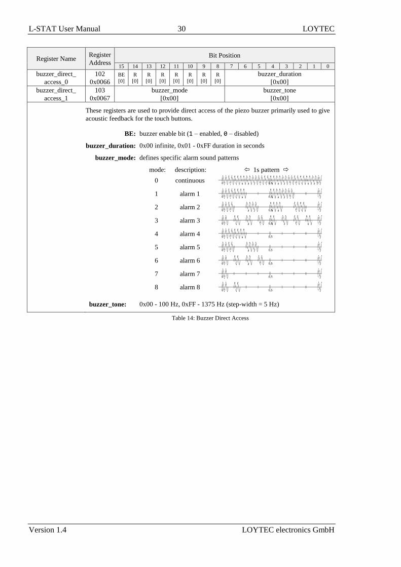
These registers are used to provide direct access of the piezo buzzer primarily used to give
acoustic feedback for the touch buttons.
BE: buzzer enable bit (1 – enabled, 0 – disabled)
buzzer_duration: 0x00 infinite, 0x01 - 0xFF duration in seconds
buzzer_mode: defines specific alarm sound patterns
mode: description: 1s pattern
0 continuous
1 alarm 1
2 alarm 2
3 alarm 3
4 alarm 4
5 alarm 5
6 alarm 6
7 alarm 7
8 alarm 8
buzzer_tone: 0x00 - 100 Hz, 0xFF - 1375 Hz (step-width = 5 Hz)
Table 14: Buzzer Direct Access

L-STAT User Manual 31 LOYTEC
Version 1.4 LOYTEC electronics GmbH
Register Name Register
Address
Bit Position
15 14 13 12 11 10 9 8 7 6 5 4 3 2 1 0
direct_value 104
0x0068 [0x0000]
direct_value_config 105
0x0069
EN
[0]
R
[0]
R
[0]
R
[0]
R
[0]
R
[0]
R
[0]
R
[0]
R
[0]
R
[0]
unit
[0x0]
exp
[00]
These registers are used to display specific values instead of display_values or set_points.
For an overview on how to setup the configuration please refer to Figure 8 on Page 24.
If disabled, the last viewed value will be visible again as defined with the
user_interface_direct_access register at adderss 101 (Table 13 on Page 29).
direct_value: 16 bit signed integer to be displayed
EN: direct value enable bit (1 – enabled, 0 – disabled)
unit: defines a unit symbol to be displayed, following values are possible:
0x0 0x1 0x2 0x3 0x4 0x5 0x6 0x7 0x8 0x9 0xA 0xB no
unit °C °F cfm l/s m³/h Pa inWC V % %RH ppm
exp: exponent, defines the number of decimal places:
00 – no decimal point
01 – one decimal place
10 – two decimal places
11 – three deciml places
Table 15: Direct Value
Register Name Register
Address
Bit Position
15 14 13 12 11 10 9 8 7 6 5 4 3 2 1 0
system_time
112
0x0070
system_time_0
[0x0000]
113
0x0071
system_time_1
[0x0000]
system_time represent a 32 bit timestamp in seconds since JAN-01-1970. The timestamp
has to be initially set by the Modbus master because the device has no back-up battery and
so it would start at 0 (00:00:00 JAN-01-1970) after a reboot. The timestamp is
incremented by the L-STAT device but anyway it has to be set by the master at defined
intervals to prevent time offsets. The timestamp is compatible with the L-INX system time
register.
Table 16: System Time

L-STAT User Manual 32 LOYTEC
Version 1.4 LOYTEC electronics GmbH
Register Name Register
Address
Bit Position
15 14 13 12 11 10 9 8 7 6 5 4 3 2 1 0
modbus_time_
cleared
128
0x0080
modbus_time_cleared_0
[0x0000]
129
0x0081
modbus_time_cleared_1
[0x0000]
modbus_rx_packets
130
0x0082
modbus_rx_packets_0
[0x0000]
131
0x0083
modbus_rx_packets_1
[0x0000]
modbus_rx_bytes
132
0x0084
modbus_rx_bytes_0
[0x0000]
133
0x0085
modbus_rx_bytes_1
[0x0000]
modbus_tx_packets
134
0x0086
modbus_tx_packets_0
[0x0000]
135
0x0087
modbus_tx_packets_1
[0x0000]
modbus_tx_bytes
136
0x0088
modbus_tx_bytes_0
[0x0000]
137
0x0089
modbus_tx_bytes_1
[0x0000]
modbus_timeout_
errors
138
0x008A
modbus_timeout_errors_0
[0x0000]
139
0x008B
modbus_timeout_errors_1
[0x0000]
modbus_checksum_
errors
140
0x008C
modbus_checksum_errors_0
[0x0000]
141
0x008D
modbus_checksum_errors_1
[0x0000]
modbus_time_cleared_0 and modbus_time_cleared_1 represent a 32 bit timestamp in
seconds since JAN-01-1970 that is set by the L-STAT device after the statistics have been
cleared by the master device.
All other values are 32 bit counters incremented by the L-STAT device. These values are
not permanently stored at the L-STAT and will be lost after a reboot.
The statistics can be cleared by setting the MSC bit at the config_flags register at
address 192 (see Table 22 on Page 36).
Table 17: Modbus Statistics

L-STAT User Manual 33 LOYTEC
Version 1.4 LOYTEC electronics GmbH
4.4.2 Device Settings
The device settings contain data to configure the device and the user interface. This registers
are also accessible through the button interface in EDIT-mode for the system administrator.
The data is stored persistently and will be preserved during power loss.
Register Name Register
Address
Bit Position
15 14 13 12 11 10 9 8 7 6 5 4 3 2 1 0
modbus_parameter 176
0x00B0
R
[0]
R
[0]
PAR
[0x2]
modbus_baud
[0x6]
device_addr
[0x01]
This register contains the configuration for the Modbus port of the LSTAT device.
Compare Table 5 on Page 20 for device settings editable via the user interface.
PAR: defines the parity bit used for Modbus communication. Valid are:
0x0 – odd (odd parity bit, 1 stop bit)
0x1 – even (even parity bit, 1 stop bit)
0x2 – none (no parity bit, 2 stop bits)
modbus_baud: defines the Modbus baudrate, following values are valid:
0x0 – 1200
0x1 – 2400
0x2 – 4800
0x3 – 9600
0x4 – 19200
0x5 – 38400
0x6 – 57600
0x7 – 115200
device_addr: defines the Modbus slave address.
Valid addresses are 1(0x01) to 247 (0xF7).
Table 18: Modbus Parameter
Register Name Register
Address
Bit Position
15 14 13 12 11 10 9 8 7 6 5 4 3 2 1 0
pincode_system_
administrator
177
0x00B1 [0x0000]
pincode_end_user 178
0x00B2 [0x0000]
pincode_system_administrator defines the pincode for the system administrator. If set to
0000 the pincode is disabled. Possible values are 0000 (0x0000) to 9999 (0x270F).
pincode_end_user defines the pincode for the end user. If set to 0000 the pincode is
disabled. Possible values are 0000 (0x0000) to 9999 (0x270F).
Compare Table 5 on Page 20 for device settings editable via the user interface.
Table 19: Pincodes

L-STAT User Manual 34 LOYTEC
Version 1.4 LOYTEC electronics GmbH
Register Name Register
Address
Bit Position
15 14 13 12 11 10 9 8 7 6 5 4 3 2 1 0
lcd_color_red 179
0x00B3
reserved
[0x00]
color_brightness
[0x64]
lcd_color_green 180
0x00B4
reserved
[0x00]
color_brightness
[0x64]
lcd_color_blue 181
0x00B5
reserved
[0x00]
color_brightness
[0x64]
lcd_brightness_
contrast
182
0x00B6
lcd_contrast
[0x64]
lcd_brightness
[0x64]
user_interface_
settings
183
0x00B7
DAD
[0x0]
GFV
[1]
AF
[1]
Time
[1]
Date
[0]
TF
[1]
DAS
[0]
R
[0]
lcd_color_scheme
[0x0]
These registers are used to configure basic features of the display and the button interface.
* As long as occupancy is detected the LCD brightness will stay at 100%. After 2 minutes
without any occupancy detected it will be dimmed to 0%.
color_brightness: defines the brightness of a specific backlight color. Values from
0x00 – 0% to 0x64 – 100% are valid.
lcd_brightness: defines the overall brightness of the LCD backlight. Values from
0x00 – 0% to 0x64 – 100% are valid.
lcd_contrast: defines the contrast setting of the LCD. Values from 0x00 – 0% to
0x64 – 100% are valid.
lcd_color_scheme: sets a predefined color setting, possible values are:
0x0 – user (as defined with the above values)
0x1 – white
0x2 – red
0x3 – green
0x4 – blue
0x5 – orange
0x6 – magenta
0x7 – cyan
DAS: display auto shuffle mode (0 – off, 1 – on), display values and set
points will be shuffled after a defined timeout of 1 minute, each
value is shown for 5 seconds
TF: time format (0 – 12h, 1 – 24h), if TF is set to 12h the date format
will also be set to MM/DD instead of DD/MM
Date: show date in secondary display (0 – off, 1 – on)
Time: show time in secondary display (0 – off, 1 – on)
AF: acoustic feedback for touch buttons (0 – off, 1 – on)
GFV: goto first value after a defined timeout of 1 minute (0 – off, 1 – on)
DAD: display auto dim, dim display brightness after 2 minutes to following
defined values:
0x0 – off (disabled)
0x1 – 50% lcd_brightness
0x2 – 10% lcd_brightness
0x3 – 0% lcd_brightness
0x4 – 0% lcd_brightness (depending on occupancy sensor *)

L-STAT User Manual 35 LOYTEC
Version 1.4 LOYTEC electronics GmbH
Register Name Register
Address Bit Position
Compare Table 5 on Page 20 for device settings editable via the user interface.
Table 20: User Interface Settings
Register Name Register
Address
Bit Position
15 14 13 12 11 10 9 8 7 6 5 4 3 2 1 0
occupancy_sensor_
config
184
0x00B8
EN
[1]
R
[0]
R
[0]
R
[0]
R
[0] R
[0]
R
[0]
R
[0]
occupancy_timeout
[0x0A]
With this register the function of occupancy sensor is enabled and controlled.
Applies only to LSTAT-801-Gx-Lx and LSTAT-802-Gx-Lx.
occupancy_timeout: defines a timeout in seconds when the state of the occupancy flag
of the short pressed register at address 1 will be cleared again
after motion was detected. Anyway the occupancy flag of the
present state register at address 0 will show the actual state of the
occupancy sensor without occupancy timeout.
Please see Figure 9 for further information on operation.
EN: occupancy sensor enabled, only if enabled the occupancy flag of
the present state and short pressed register at address 0 and 1,
Table 7 on Page 26 will be set.
Table 21: Occupancy Sensor Configuration
As depicted in Figure 9 the occupancy flag is set when motion is detected and will be
cleared again after the occupancy_timeout has exceeded as defined at the
occupancy_sensor_configuration register.
Figure 9: Occupancy Sensor Operation

L-STAT User Manual 36 LOYTEC
Version 1.4 LOYTEC electronics GmbH
4.4.3 Configuration Registers
The configuration registers contain data for configuring fundamental functions of the device
as well as configurations for display values and set points. The data is stored persistent and
will be preserved after reboot.
Register Name Register
Address
Bit Position
15 14 13 12 11 10 9 8 7 6 5 4 3 2 1 0
config_flags 192
0x00C0
R
[0]
SDSV
[0]
MSC
[0]
IRCP
[0]
DU
[0x1]
MU
[0x1]
VIE
[0]
VOL
[1]
AIE
[0]
AOL
[0]
PESA
[1]
PEEU
[1]
SDE
[0]
RST
[0]
RST: reset_device flag, set to ‘1’ the device will reboot
SDE: secondary_display_direct_access_enabled flag, set to ‘1’ the device displays
the content of the secondary_display_direct_access_string register at address
200 (see Table 23 on Page 37)
PEEU: pincode_enabled_for_end_user flag, if set to ‘1’ the pincode for the end user
can be edited by the end user
PESA: pincode_enabled_for_system_administrator flag, if set to ‘1’ the pincode for
the end user and the system administrator can be edited by the system
administrator
AOL: acoustic_alarm_when_offline flag, if set to ‘1’ a buzzer tone will be generated
while the device is offline
AIE: acoustic_alarm_on_internal_error flag, if set to ‘1’ a buzzer tone will be
generated if an internal error occurred
VOL: visual_alarm_when_offline flag, if set to ‘1’ the offline text symbol (
) will be displayed while the device is offline
VIE: visual_alarm_on_internal_error flag, if set to ‘1’ the alarm symbol ( ) will be
displayed if an internal error occurred
MU: modbus_unit, defines which unit system is used for values on Modbus. The
following values are possible:
0x0 – K
0x1 – °C (SI)
0x2 – °F (US)
DU: display_unit, defines which unit system is used to display values on the L-STAT.
The following values are possible:
0x0 – access prohibited via the user interface
0x1 – °C (SI)
0x2 – °F (US)
The display_unit can also be changed via the user interface in the device
settings (see Table 5 an Page 20). If the value is set to ‘00’ the access to this
device setting via the user interface is prohibited.
IRCP: ir_remote_control_pairing flag, for further information see Section 6.2
MSC: modbus_statistics_clear flag, for further information see Table 17 on Page 32
SDSV: secondary_display_direct_access_string_volatile flag, if set to ‘1’ the content
of secondary_display_direct_access_string (Table 23 on Page 37) is not kept
persistent. This should be considered when the content of this register is
changed frequently because of the limited write cycles of persistent memory.
Table 22: Configuration Flags

L-STAT User Manual 37 LOYTEC
Version 1.4 LOYTEC electronics GmbH
Please note that a change of display_unit or modbus_unit at the config_flags register will
change the configuration registers for display values at address 256 to 289 and set points at
address 320 to 351 to match the selected units system. Please see Table 28 on Page 42 for
display value configuration and Table 29 on Page 44 for set point configuration.
If the direct value registers at adderss 104 and 105 (see Table 15 on Page 31) are used to
display certain values there is no need to set the SDE flag at the config_flags register (see
Table 22 on Page 36) to show a text along with the value. If the direct value enable bit is set
to ‘1’ the content of sec_display_direct_access_string will be checked by the device. If the
string is empty time and/or date will be displayed if enabled at user_interface_settings at
addresse 183 (Table 20 on Page 35). Otherwise the content of the string will be displayed
automatically. If it is desired to don´t show anything at the secondary display a space
character (0x20) needs to be inserted.
Register Name Register
Address Bit Position
15 14 13 12 11 10 9 8 7 6 5 4 3 2 1 0
secondary_display_
direct_access_string
200
0x00C8
sec_display_direct_access_string –
207
0x00CF
The string will be displayed with the 4x16 segment digits of the
secondary display. The string will be updated if the secondary_display_direct_access_enabled flag at the
config_flags register at address 192 (Table 22 at Page 36) is set.
Up to 16 ASCII character (limited to characters from 0x20 to 0x5F) can be displayed.
A string terminator (0x00) will determine the length of the string. If a string is longer
than 4 characters the secondary display will work as a ticker.
Table 23: Secondary Display Direct Access String

L-STAT User Manual 38 LOYTEC
Version 1.4 LOYTEC electronics GmbH
Register Name Register
Address
Bit Position
15 14 13 12 11 10 9 8 7 6 5 4 3 2 1 0
config_touch_
button_0
208
0x00D0
DA
[1]
ED
[0]
EU
[1]
DAD
[0]
DAU
[1]
MF
[0]
R
[0]
EN
[1]
set_point_index
[0x00]
config_touch_
button_1
209
0x00D1
DA
[1]
ED
[0]
EU
[1]
DAD
[0]
DAU
[1]
MF
[0]
R
[0]
EN
[1]
set_point_index
[0x01]
config_touch_
button_2
210
0x00D2
DA
[0]
ED
[0]
EU
[0]
DAD
[0]
DAU
[0]
MF
[0]
R
[0]
EN
[1]
set_point_index
[0x00]
config_touch_
button_3
211
0x00D3
DA
[0]
ED
[0]
EU
[0]
DAD
[0]
DAU
[0]
MF
[1]
R
[0]
EN
[1]
set_point_index
[0x00]
config_touch_
button_4
212
0x00D4
DA
[1]
ED
[1]
EU
[0]
DAD
[1]
DAU
[0]
MF
[0]
R
[0]
EN
[1]
set_point_index
[0x00]
config_touch_
button_5
213
0x00D5
DA
[1]
ED
[1]
EU
[0]
DAD
[1]
DAU
[0]
MF
[0]
R
[0]
EN
[1]
set_point_index
[0x01]
config_touch_
button_6
214
0x00D6
DA
[0]
ED
[0]
EU
[0]
DAD
[0]
DAU
[0]
MF
[0]
R
[0]
EN
[1]
set_point_index
[0x00]
config_touch_
button_7
215
0x00D7
DA
[0]
ED
[0]
EU
[0]
DAD
[0]
DAU
[0]
MF
[0]
R
[0]
EN
[1]
set_point_index
[0x00]
With these registers the functionality of the touch buttons is defined.
See Table 26 on Page 40 for example configurations.
set_point_index: defines a set point register that can be edited in DIRECT_ACCESS-
mode if the DA bit is set
EN: if set to ‘1’ the defined button is enabled and its state will be updated
in the present state, short pressed and long pressed register at Table 7
on Page 26
MF: if set to ‘1’ the button is defined as MENU-button
DAU: if set to ‘1’ the button is defined as UP-button
in DIRECT_ACCESS-mode
DAD: if set to ‘1’ the button is defined as DOWN-button in
DIRECT_ACCESS-mode
EU: if set to ‘1’ the button is defined as UP-button in EDIT-mode
ED: if set to ‘1’ the button is defined as DOWN-button in EDIT-mode
DA: if set to ‘1’ and the button gets pressed a set point defined by the
set_point_index will be displayed in DIRECT_ACCESS-mode
Table 24: Touch Button Configuration

L-STAT User Manual 39 LOYTEC
Version 1.4 LOYTEC electronics GmbH
Register Name Register
Address
Bit Position
15 14 13 12 11 10 9 8 7 6 5 4 3 2 1 0
config_external_
button_0
224
0x00E0
DA
[0]
ED
[0]
EU
[0]
DAD
[0]
DAU
[0]
MF
[0]
R
[0]
EN
[1]
set_point_index
[0x00]
config_external_
button_1
225
0x00E1
DA
[0]
ED
[0]
EU
[0]
DAD
[0]
DAU
[0]
MF
[0]
R
[0]
EN
[1]
set_point_index
[0x00]
config_external_
button_2
226
0x00E2
DA
[0]
ED
[0]
EU
[0]
DAD
[0]
DAU
[0]
MF
[0]
R
[0]
EN
[1]
set_point_index
[0x00]
config_external_
button_3
227
0x00E3
DA
[0]
ED
[0]
EU
[0]
DAD
[0]
DAU
[0]
MF
[0]
R
[0]
EN
[1]
set_point_index
[0x00]
With these registers the functionality of the external buttons is defined.
See Table 26 on Page 40 for example configurations.
set_point_index: defines a set point register that can be edited in DIRECT_ACCESS-
mode if the DA bit is set
EN: if set to ‘1’ the defined button is enabled and its state will be updated
in the present state, short pressed and long pressed register at Table 7
on Page 26
MF: if set to ‘1’ the button is defined as MENU-button
DAU: if set to ‘1’ the button is defined as UP-button
in DIRECT_ACCESS-mode
DAD: if set to ‘1’ the button is defined as DOWN-button in
DIRECT_ACCESS-mode
EU: if set to ‘1’ the button is defined as UP-button in EDIT-mode
ED: if set to ‘1’ the button is defined as DOWN-button in EDIT-mode
DA: if set to ‘1’ and the button gets pressed a set point defined by the
set_point_index will be displayed in DIRECT_ACCESS-mode
Table 25: External Button Configuration

L-STAT User Manual 40 LOYTEC
Version 1.4 LOYTEC electronics GmbH
Description Bit Position
15 14 13 12 11 10 9 8 7 6 5 4 3 2 1 0
no special function 0 0 0 0 0 0 0 1 0
The button is enabled but has no special function (e.g. OCCUPANCY-button). The set
point index has no influence in this case.
MENU-button 0 0 0 0 0 1 0 1 0
This combination can be used to determine the MENU-button. The set point index has no
influence in this case.
UP-button 0 0 1 0 1 0 0 1 0
This button will increment a set point in EDIT- or DIRECT_ACCESS-mode when
pressed. The set point index has no influence in this case.
DOWN-button with
direct access 1 1 0 1 0 0 0 1 0
This button will decrement a set point in EDIT- or DIRECT_ACCESS-mode when
pressed. Additionally a setpoint defined with the set_point_index is displayed when
pressed and can be edited in DIRECT_ACCESS-mode.
Table 26: Button Example Configuration
Register Name Register
Address
Bit Position
15 14 13 12 11 10 9 8 7 6 5 4 3 2 1 0
config_bar_
graph_left
240
0x00F0
R
[0]
R
[0]
R
[0]
R
[0]
R
[0]
R
[0]
R
[0]
EN
[0]
set_point_index
[0x00]
config_bar_
graph_right
241
0x00F1
R
[0]
R
[0]
R
[0]
R
[0]
R
[0]
R
[0]
R
[0]
EN
[1]
set_point_index
[0x01]
These registers are used to associate a set point as source for the bar graph on the left and
on the right side of the LCD. If enabled the bar graph is updated corresponding to the
value of the set point defined with the set_point_index.
The bar graph segments can also be set manually by writing the symbol_direct_access
registers at address 99 and 100 (Table 12 on Page 29).
set_point_index: defines a set point register that is used as source for the bar graph
EN: if set to ‘1’ the corresponding bar-graph will be updated to visualize
the value of a set point with the defined set_point_index
Table 27: Bar Graph Configuration

L-STAT User Manual 41 LOYTEC
Version 1.4 LOYTEC electronics GmbH
Register Name Register
Address
Bit Position
15 14 13 12 11 10 9 8 7 6 5 4 3 2 1 0
config_display_
value_0
256
0x0100
unit_modbus
[0x1]
unit_lstat
[0x1]
CAL
[1]
semantic_meaning
[0x01]
257
0x0101
VSA
[1]
VEU
[1]
DSSA
[1]
DSEU
[1]
[0]
[0]
[0]
[0]
[0]
[0]
[0]
[0]
[0]
[0]
[1]
[0]
config_display_
value_1
258
0x0102
unit_modbus
[0xA]
unit_lstat
[0xA]
CAL
[1]
semantic_meaning
[0x04]
259
0x0103
VSA
[1]
VEU
[1]
DSSA
[1]
DSEU
[1]
[0]
[0]
[0]
[0]
[1]
[0]
[0]
[0]
[0]
[0]
[0]
[0]
config_display_
value_2
260
0x0104
unit_modbus
[0x1]
unit_lstat
[0x1]
CAL
[1]
semantic_meaning
[0x05]
261
0x0105
VSA
[1]
VEU
[1]
DSSA
[1]
DSEU
[1]
[0]
[0]
[0]
[0]
[1]
[0]
[0]
[0]
[0]
[0]
[1]
[0]
config_display_
value_3 *
262
0x0106
unit_modbus
[0xB]
unit_lstat
[0xB]
CAL
[1]
semantic_meaning
[0x07]
263
0x0107
VSA
[1]
VEU
[1]
DSSA
[1]
DSEU
[1]
[0]
[0]
[0]
[0]
[0]
[0]
[0]
[0]
[0]
[0]
[0]
[0]
config_display_
value_4
264
0x0108
unit_modbus
[0x8]
unit_lstat
[0x8]
CAL
[1]
semantic_meaning
[0x0E]
265
0x0109
VSA
[1]
VEU
[1]
DSSA
[1]
DSEU
[1]
[0]
[0]
[0]
[0]
[0]
[0]
[0]
[0]
[0]
[0]
[0]
[0]
config_display_
value_5
266
0x010A
unit_modbus
[0x1]
unit_lstat
[0x1]
CAL
[1]
semantic_meaning
[0x03]
267
0x010B
VSA
[1]
VEU
[1]
DSSA
[1]
DSEU
[1]
[0]
[0]
[0]
[0]
[0]
[0]
[0]
[0]
[0]
[1]
[0]
[0]
config_display_
value_6
268
0x010C
unit_modbus
[0x0]
unit_lstat
[0x0]
CAL
[0]
semantic_meaning
[0x00]
269
0x010D
VSA
[0]
VEU
[0]
DSSA
[0]
DSEU
[0]
[0]
[0]
[0]
[0]
[0]
[0]
[0]
[0]
[0]
[0]
[0]
[0]
config_display_
value_7
270
0x010E
unit_modbus
[0x0]
unit_lstat
[0x0]
CAL
[0]
semantic_meaning
[0x00]
271
0x010F
VSA
[0]
VEU
[0]
DSSA
[0]
DSEU
[0]
[0]
[0]
[0]
[0]
[0]
[0]
[0]
[0]
[0]
[0]
[0]
[0]
config_display_
value_8
272
0x0110
unit_modbus
[0x0]
unit_lstat
[0x0]
CAL
[0]
semantic_meaning
[0x00]
273
0x0111
VSA
[0]
VEU
[0]
DSSA
[0]
DSEU
[0]
[0]
[0]
[0]
[0]
[0]
[0]
[0]
[0]
[0]
[0]
[0]
[0]
config_display_
value_9
274
0x0112
unit_modbus
[0x0]
unit_lstat
[0x0]
CAL
[0]
semantic_meaning
[0x00]
275
0x0113
VSA
[0]
VEU
[0]
DSSA
[0]
DSEU
[0]
[0]
[0]
[0]
[0]
[0]
[0]
[0]
[0]
[0]
[0]
[0]
[0]
config_display_
value_10
276
0x0114
unit_modbus
[0x0]
unit_lstat
[0x0]
CAL
[0]
semantic_meaning
[0x00]
277
0x0115
VSA
[0]
VEU
[0]
DSSA
[0]
DSEU
[0]
[0]
[0]
[0]
[0]
[0]
[0]
[0]
[0]
[0]
[0]
[0]
[0]
config_display_
value_11
278
0x0116
unit_modbus
[0x0]
unit_lstat
[0x0]
CAL
[0]
semantic_meaning
[0x00]
279
0x0117
VSA
[0]
VEU
[0]
DSSA
[0]
DSEU
[0]
[0]
[0]
[0]
[0]
[0]
[0]
[0]
[0]
[0]
[0]
[0]
[0]
config_display_
value_12
280
0x0118
unit_modbus
[0x0]
unit_lstat
[0x0]
CAL
[0]
semantic_meaning
[0x00]
281
0x0119
VSA
[0]
VEU
[0]
DSSA
[0]
DSEU
[0]
[0]
[0]
[0]
[0]
[0]
[0]
[0]
[0]
[0]
[0]
[0]
[0]

L-STAT User Manual 42 LOYTEC
Version 1.4 LOYTEC electronics GmbH
Register Name Register
Address Bit Position
config_display_
value_13
282
0x011A
unit_modbus
[0x0]
unit_lstat
[0x0]
CAL
[0]
semantic_meaning
[0x00]
283
0x011B
VSA
[0]
VEU
[0]
DSSA
[0]
DSEU
[0]
[0]
[0]
[0]
[0]
[0]
[0]
[0]
[0]
[0]
[0]
[0]
[0]
config_display_
value_14
284
0x011C
unit_modbus
[0x0]
unit_lstat
[0x0]
CAL
[0]
semantic_meaning
[0x00]
285
0x011D
VSA
[0]
VEU
[0]
DSSA
[0]
DSEU
[0]
[0]
[0]
[0]
[0]
[0]
[0]
[0]
[0]
[0]
[0]
[0]
[0]
config_display_
value_15
286
0x011E
unit_modbus
[0x0]
unit_lstat
[0x0]
CAL
[0]
semantic_meaning
[0x00]
287
0x011F
VSA
[0]
VEU
[0]
DSSA
[0]
DSEU
[0]
[0]
[0]
[0]
[0]
[0]
[0]
[0]
[0]
[0]
[0]
[0]
[0]
These registers hold the configuration of the 16 display values.
For both, unit_lstat and unit_modbus the following values are possible:
0x0 0x1 0x2 0x3 0x4 0x5 0x6 0x7 0x8 0x9 0xA 0xB 0xC no
unit °C °F cfm l/s m³/h Pa inWC V % %RH ppm °F dec.
Bits 0-11 of the higher address of each configuration register indicate the symbols that are
displayed along with the corresponding display value.
These two bits define if the value displayed is taken from a display_value register at address
64 to 79 (see Table 11 on Page 28) or from a sensor_value register at address 48 to 56 (see
Table 10 on Page 27). The following states are valid:
0 – defines that the value is taken from a display_value register that has to be set via
modbus
1 – defines that the value is taken from a sensor_value (+ offset_value) register that is
automatically updated with the current sensor value
VEU: visible for end user
VSA: visible for system administrator
These two bits define if the display value is visible for the end user and/or the system
administrator. If set to ‘1’ the value will be visible.
See Table 31 on Page 46 for example configurations of display values or set points.
* Please note that config_display_value_3 register is only configured as above per default
for LSTAT-802-Gx-Lx devices for displaying the actual CO2 level. Otherwise all bits of
this register are set to ‘0’.
semantic_meaning: is used to provide information about the semantic meaning and the
source of the value. For further information please see Table 30 on
Page 45.
CAL: if set to ‘1’ the corresponding offset_value can be edited in
CALIBRATION-mode (only capable if DSEU or DSSA is set to
‘1’)
unit_lstat: defines a unit with which the corresponding display value appears
on the LCD
unit_modbus: defines a unit that the corresponding display value register appeare
on Modbus
DSEU: display source for end user
DSSA: diplay source for system administrator
Table 28: Display Value Configuration

L-STAT User Manual 43 LOYTEC
Version 1.4 LOYTEC electronics GmbH
Register Name Register
Address
Bit Position
15 14 13 12 11 10 9 8 7 6 5 4 3 2 1 0
config_set_
point_0
320
0x0140
unit_modbus
[0x1]
unit_lstat
[0x1]
PIN
[0]
semantic_meaning
[0x01]
321
0x0141
VSA
[1]
VEU
[1]
ESA
[1]
EEU
[1]
[0]
[0]
[0]
[0]
[0]
[0]
[0]
[0]
[0]
[0]
[1]
[1]
config_set_
point _1
322
0x0142
unit_modbus
[0x0]
unit_lstat
[0x0]
PIN
[0]
semantic_meaning
[0x0B]
323
0x0143
VSA
[1]
VEU
[1]
ESA
[1]
EEU
[1]
[0]
[0]
[0]
[0]
[0]
[0]
[1]
[0]
[0]
[0]
[0]
[0]
config_set_
point _2
324
0x0144
unit_modbus
[0x0]
unit_lstat
[0x0]
PIN
[0]
semantic_meaning
[0x00]
325
0x0145
VSA
[0]
VEU
[0]
ESA
[0]
EEU
[0]
[0]
[0]
[0]
[0]
[0]
[0]
[0]
[0]
[0]
[0]
[0]
[0]
config_set_
point _3
326
0x0146
unit_modbus
[0x0]
unit_lstat
[0x0]
PIN
[0]
semantic_meaning
[0x00]
327
0x0147
VSA
[0]
VEU
[0]
ESA
[0]
EEU
[0]
[0]
[0]
[0]
[0]
[0]
[0]
[0]
[0]
[0]
[0]
[0]
[0]
config_set_
point _4
328
0x0148
unit_modbus
[0x0]
unit_lstat
[0x0]
PIN
[0]
semantic_meaning
[0x00]
329
0x0149
VSA
[0]
VEU
[0]
ESA
[0]
EEU
[0]
[0]
[0]
[0]
[0]
[0]
[0]
[0]
[0]
[0]
[0]
[0]
[0]
config_set_
point _5
330
0x014A
unit_modbus
[0x0]
unit_lstat
[0x0]
PIN
[0]
semantic_meaning
[0x00]
331
0x014B
VSA
[0]
VEU
[0]
ESA
[0]
EEU
[0]
[0]
[0]
[0]
[0]
[0]
[0]
[0]
[0]
[0]
[0]
[0]
[0]
config_set_
point _6
332
0x014C
unit_modbus
[0x0]
unit_lstat
[0x0]
PIN
[0]
semantic_meaning
[0x00]
333
0x014D
VSA
[0]
VEU
[0]
ESA
[0]
EEU
[0]
[0]
[0]
[0]
[0]
[0]
[0]
[0]
[0]
[0]
[0]
[0]
[0]
config_set_
point _7
334
0x014E
unit_modbus
[0x0]
unit_lstat
[0x0]
PIN
[0]
semantic_meaning
[0x00]
335
0x014F
VSA
[0]
VEU
[0]
ESA
[0]
EEU
[0]
[0]
[0]
[0]
[0]
[0]
[0]
[0]
[0]
[0]
[0]
[0]
[0]
config_set_
point _8
336
0x0150
unit_modbus
[0x0]
unit_lstat
[0x0]
PIN
[0]
semantic_meaning
[0x00]
337
0x0151
VSA
[0]
VEU
[0]
ESA
[0]
EEU
[0]
[0]
[0]
[0]
[0]
[0]
[0]
[0]
[0]
[0]
[0]
[0]
[0]
config_set_
point _9
338
0x0152
unit_modbus
[0x0]
unit_lstat
[0x0]
PIN
[0]
semantic_meaning
[0x00]
339
0x0153
VSA
[0]
VEU
[0]
ESA
[0]
EEU
[0]
[0]
[0]
[0]
[0]
[0]
[0]
[0]
[0]
[0]
[0]
[0]
[0]
config_set_
point _10
340
0x0154
unit_modbus
[0x0]
unit_lstat
[0x0]
PIN
[0]
semantic_meaning
[0x00]
341
0x0155
VSA
[0]
VEU
[0]
ESA
[0]
EEU
[0]
[0]
[0]
[0]
[0]
[0]
[0]
[0]
[0]
[0]
[0]
[0]
[0]
config_set_
point _11
342
0x0156
unit_modbus
[0x0]
unit_lstat
[0x0]
PIN
[0]
semantic_meaning
[0x00]
343
0x0157
VSA
[0]
VEU
[0]
ESA
[0]
EEU
[0]
[0]
[0]
[0]
[0]
[0]
[0]
[0]
[0]
[0]
[0]
[0]
[0]
config_set_
point _12
344
0x0158
unit_modbus
[0x0]
unit_lstat
[0x0]
PIN
[0]
semantic_meaning
[0x00]
345
0x0159
VSA
[0]
VEU
[0]
ESA
[0]
EEU
[0]
[0]
[0]
[0]
[0]
[0]
[0]
[0]
[0]
[0]
[0]
[0]
[0]

L-STAT User Manual 44 LOYTEC
Version 1.4 LOYTEC electronics GmbH
Register Name Register
Address Bit Position
config_set_
point _13
346
0x015A
unit_modbus
[0x0]
unit_lstat
[0x0]
PIN
[0]
semantic_meaning
[0x00]
347
0x015B
VSA
[0]
VEU
[0]
ESA
[0]
EEU
[0]
[0]
[0]
[0]
[0]
[0]
[0]
[0]
[0]
[0]
[0]
[0]
[0]
config_set_
point _14
348
0x015C
unit_modbus
[0x0]
unit_lstat
[0x0]
PIN
[0]
semantic_meaning
[0x00]
349
0x015D
VSA
[0]
VEU
[0]
ESA
[0]
EEU
[0]
[0]
[0]
[0]
[0]
[0]
[0]
[0]
[0]
[0]
[0]
[0]
[0]
config_set_
point _15
350
0x015E
unit_modbus
[0x0]
unit_lstat
[0x0]
PIN
[0]
semantic_meaning
[0x00]
351
0x015F
VSA
[0]
VEU
[0]
ESA
[0]
EEU
[0]
[0]
[0]
[0]
[0]
[0]
[0]
[0]
[0]
[0]
[0]
[0]
[0]
These registers hold the configuration for the 16 set point.
For both, unit_lstat and unit_modbus the following values are possible:
0x0 0x1 0x2 0x3 0x4 0x5 0x6 0x7 0x8 0x9 0xA 0xB 0xC no
unit °C °F cfm l/s m³/h Pa inWC V % %RH ppm °F dec.
Bits 0-11 of the higher address of each configuration register indicate the symbols that are
displayed along with the corresponding display value.
These two bits define if the set point is editable for the end user and/or the system
administrator. The following states are valid:
0 – defines that the set point is not editable
1 – defines that the set point is editable
VEU: visible for end user
VSA: visible for system administrator
These two bits define if the set point is visible for the end user and/or the system administrator.
If set to ‘1’ the set point will be visible.
See Table 31 on Page 46 for example configurations of display values or set points.
semantic_meaning: is used to provide information about the semantic meaning of the set
point. For further information please see Table 30 on Page 45.
PIN: if set to ‘1’ the the corresponding set point is pincode protected and
can only be changed in EDIT-mode if the correct pincode has been
entered before.
unit_lstat: defines a unit with which the corresponding set point appears on
the LCD
unit_modbus: defines a unit that the corresponding set point register appears on
Modbus
EEU: editable for end user
ESA: editable for system administrator
Table 29: Set Point Configuration

L-STAT User Manual 45 LOYTEC
Version 1.4 LOYTEC electronics GmbH
Table 30 below shows possible values for the semantic meaning used in the configuration
for display values (Table 28 on Page 42) and set points (Table 29 on Page 44).
Primarily the semantic meaning field defines a text that is displayed along with a display
value or a set point. Additionally for display values it defines the internal sensor_value that
is displayed when the DSEU or DSSA bit is set. For examples on how to use the semantic
meaning field in the configuration registers please see Table 31 on Page 46.
Semantic Meaning Value Description Secondary Display Text
0x00 None (unconfigured)
0x01 Internal Temperature abs. R O O M
0x02 Internal Temperature rel. ∆ S P T
0x03 External Temperature O U T
0x04 Relative Humidity H U M
0x05 Dew Point D E W
0x06 Luminance (lx) L U X
0x07 Amount CO2 C O 2
0x08 Differential Pressure P R E S
0x09 Flow F L O W
0x0A Valve Position V A L V
0x0B Fan Stage F A N
0x0C Heat/Cool Stage H & C
0x0D Brightness (%) B R %
0x0E Supply Voltage 2 4 V
0x0F CPU voltage C P U
0x10 CPU temperature C P U
0x11 Room ID R O O M
0x12 Damper Position (%) D A M P
0x13 Reheat (%) H E A T
0x14 Discharge Temperature D I S
Table 30: Semantic Meaning
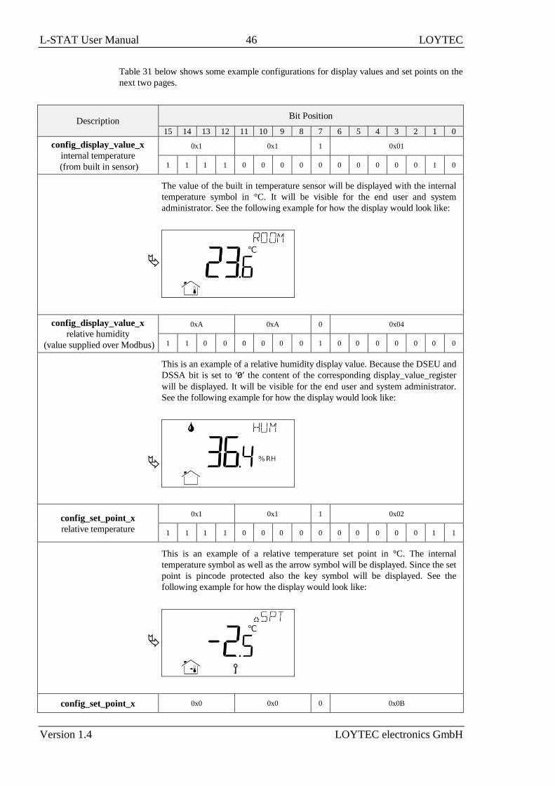
L-STAT User Manual 46 LOYTEC
Version 1.4 LOYTEC electronics GmbH
Table 31 below shows some example configurations for display values and set points on the
next two pages.
Description Bit Position
15 14 13 12 11 10 9 8 7 6 5 4 3 2 1 0
config_display_value_x
internal temperature
(from built in sensor)
0x1 0x1 1 0x01
1 1 1 1 0 0 0 0 0 0 0 0 0 0 1 0
The value of the built in temperature sensor will be displayed with the internal
temperature symbol in °C. It will be visible for the end user and system
administrator. See the following example for how the display would look like:
config_display_value_x
relative humidity
(value supplied over Modbus)
0xA 0xA 0 0x04
1 1 0 0 0 0 0 0 1 0 0 0 0 0 0 0
This is an example of a relative humidity display value. Because the DSEU and
DSSA bit is set to ‘0’ the content of the corresponding display_value_register
will be displayed. It will be visible for the end user and system administrator.
See the following example for how the display would look like:
config_set_point_x
relative temperature
0x1 0x1 1 0x02
1 1 1 1 0 0 0 0 0 0 0 0 0 0 1 1
This is an example of a relative temperature set point in °C. The internal
temperature symbol as well as the arrow symbol will be displayed. Since the set
point is pincode protected also the key symbol will be displayed. See the
following example for how the display would look like:
config_set_point_x 0x0 0x0 0 0x0B

L-STAT User Manual 47 LOYTEC
Version 1.4 LOYTEC electronics GmbH
Description Bit Position
fan stage 1 1 1 1 0 0 0 0 0 0 1 0 0 0 0 0
This is an example of a fan stage set point. The fan symbol and the actual stage
will be displayed. The bar graph showing the actual stage of the fan is not
displayed automatically but can be enabled via the corresponding bar graph
configuration register at address 240-241 (see Table 27 on Page 40). See the
following example for how the display would look like:
For a stage set point the following semantic meanings are possible:
The user can adjust the set point in manual mode within the limits defined by
the set point max and min values (see Table 33 and Table 34). The automatic
mode can be displayed by writing defined values to the specific set point
register (see Table 32). The following values are possible:
If the set point min value is set to any automatic stage the user will have the
opportunity to switch between manual and automatic mode. In this case, if the
set point max value is set to “Stage 3 Manual” for example, the user can select
the following values:
Stage 3 Manual
Stage 2 Manual
Stage 1 Manual
Stage 0 Manual
Stage 0 Auto
0x0A … Valve Position
0x0B … Fan Stage
0x0C … Heat/Cool Stage
0x0000 … Stage 0 Manual
0x0001… Stage 1 Manual
0x0002 … Stage 2 Manual
0x0003 … Stage 3 Manual
0x8000 … Stage 0 Auto
0x8001 … Stage 1 Auto
0x8002 … Stage 2 Auto
0x8003 … Stage 3 Auto
Table 31: Display Value and Set Point Example Configuration

L-STAT User Manual 48 LOYTEC
Version 1.4 LOYTEC electronics GmbH
Register Name Register
Address Bit Position
15 14 13 12 11 10 9 8 7 6 5 4 3 2 1 0
set_point_0 384
0x0180 [0x00DC]
set_point_1 385
0x0181 [0x0000]
set_point_2 386
0x0182 [0x0000]
set_point_3 387
0x0183 [0x0000]
set_point_4 388
0x0184 [0x0000]
set_point_5 389
0x0185 [0x0000]
set_point_6 390
0x0186 [0x0000]
set_point_7 391
0x0187 [0x0000]
set_point_8 392
0x0188 [0x0000]
set_point_9 393
0x0189 [0x0000]
set_point_10 394
0x018A [0x0000]
set_point_11 395
0x018B [0x0000]
set_point_12 396
0x018C [0x0000]
set_point_13 397
0x018D [0x0000]
set_point_14 398
0x018E [0x0000]
set_point_15 399
0x018F [0x0000]
These registers contain the values of up to 16 set points.
All registers are 16 Bit signed values. Depending on the modbus_unit specified with the
corresponding set point configuration register at address 320 to 351 (Table 29 at Page 44)
the value needs to be scaled as described in Table 39 at Page 56 to achieve the desired
result.
Table 32: Set Points

L-STAT User Manual 49 LOYTEC
Version 1.4 LOYTEC electronics GmbH
Register Name Register
Address Bit Position
15 14 13 12 11 10 9 8 7 6 5 4 3 2 1 0
set_point_max_0 416
0x01A0 [0x012C]
set_point_max_1 417
0x01A1 [0x0003]
set_point_max_2 418
0x01A2 [0x0000]
set_point_max_3 419
0x01A3 [0x0000]
set_point_max_4 420
0x01A4 [0x0000]
set_point_max_5 421
0x01A5 [0x0000]
set_point_max_6 422
0x01A6 [0x0000]
set_point_max_7 423
0x01A7 [0x0000]
set_point_max_8 424
0x01A8 [0x0000]
set_point_max_9 425
0x01A9 [0x0000]
set_point_max_10 426
0x01AA [0x0000]
set_point_max_11 427
0x01AB [0x0000]
set_point_max_12 428
0x01AC [0x0000]
set_point_max_13 429
0x01AD [0x0000]
set_point_max_14 430
0x01AE [0x0000]
set_point_max_15 431
0x01AF [0x0000]
These registers are used to allow set point changes for the end user or system administrator
only within limits defined with a set_point_max value of this Table and a set_point_min
value of Table 34.
All registers are 16 Bit signed values. Depending on the modbus_unit specified with the
corresponding set point configuration register at address 320 to 351 (Table 29 at Page 44)
the value needs to be scaled as described in Table 39 at Page 56 to achieve the desired
result.
Table 33: Set Point max. Values

L-STAT User Manual 50 LOYTEC
Version 1.4 LOYTEC electronics GmbH
Register Name Register
Address Bit Position
15 14 13 12 11 10 9 8 7 6 5 4 3 2 1 0
set_point_min_0 448
0x01C0 [0x0096]
set_point_min_1 449
0x01C1 [0x0000]
set_point_min_2 450
0x01C2 [0x0000]
set_point_min_3 451
0x01C3 [0x0000]
set_point_min_4 452
0x01C4 [0x0000]
set_point_min_5 453
0x01C5 [0x0000]
set_point_min_6 454
0x01C6 [0x0000]
set_point_min_7 455
0x01C7 [0x0000]
set_point_min_8 456
0x01C8 [0x0000]
set_point_min_9 457
0x01C9 [0x0000]
set_point_min_10 458
0x01CA [0x0000]
set_point_min_11 459
0x01CB [0x0000]
set_point_min_12 460
0x01CC [0x0000]
set_point_min_13 461
0x01CD [0x0000]
set_point_min_14 462
0x01CE [0x0000]
set_point_min_15 463
0x01CF [0x0000]
These registers are used to allow set point changes for the end user or system administrator
only within limits defined with a set_point_max value of Table 33 and a set_point_min
value of this Table.
All registers are 16 Bit signed values. Depending on the modbus_unit specified with the
corresponding set point configuration register at address 320 to 351 (Table 29 at Page 44)
the value needs to be scaled as described in Table 39 at Page 56 to achieve the desired
result.
Table 34: Set Point min. Values

L-STAT User Manual 51 LOYTEC
Version 1.4 LOYTEC electronics GmbH
Register Name Register
Address Bit Position
15 14 13 12 11 10 9 8 7 6 5 4 3 2 1 0
offset_value_0 480
0x01E0 [0x0000]
offset_value_1 481
0x01E1 [0x0000]
offset_value_2 482
0x01E2 [0x0000]
offset_value_3 483
0x01E3 [0x0000]
offset_value_4 484
0x01E4 [0x0000]
offset_value_5 485
0x01E5 [0x0000]
offset_value_6 486
0x01E6 [0x0000]
offset_value_7 487
0x01E7 [0x0000]
offset_value_8 488
0x01E8 [0x0000]
offset_value_9 489
0x01E9 [0x0000]
offset_value_10 490
0x01EA [0x0000]
offset_value_11 491
0x01EB [0x0000]
offset_value_12 492
0x01EC [0x0000]
offset_value_13 493
0x01ED [0x0000]
offset_value_14 494
0x01EE [0x0000]
offset_value_15 495
0x01EF [0x0000]
These registers are used to define offsets for display values when displaying a value from a
built in sensor. These registers can either be written via Modbus or can be edited in
CALIBRATION-mode by the system administrator.
All registers are 16 Bit signed values. Depending on the modbus_unit specified with the
corresponding display value configuration register at address 256 to 287 (Table 28 at Page
42) the value needs to be scaled the same as the corresponding display value as described
in Table 39 at Page 56.
Table 35: Offset Values

L-STAT User Manual 52 LOYTEC
Version 1.4 LOYTEC electronics GmbH
4.4.4 Model Information Registers (read only)
These registers are set at production time and contain specific information about the specific
model and the default button print layout.
Register Name Register
Address
Buttonlayout
LSTAT-80x-Gx-… Default Value
default_print_
touch_button_0
528
0x0210
L1 [0x0004]
L2 [0x0004]
L3 [0x0004]
L4 [0x0004]
L5 [0x0004]
L6 [0x0004]
default_print_
touch_button_1
529
0x0211
L1 [0x0000]
L2 [0x0006]
L3 [0x0006]
L4 [0x000A]
L5 [0x0006]
L6 [0x0006]
default_print_
touch_button_2
530
0x0212
L1 [0x0000]
L2 [0x0000]
L3 [0x0008]
L4 [0x0008]
L5 [0x000A]
L6 [0x000A]
default_print_
touch_button_3
531
0x0213
L1 [0x0001]
L2 [0x0001]
L3 [0x0001]
L4 [0x0001]
L5 [0x0001]
L6 [0x0001]
default_print_
touch_button_4
532
0x0214
L1 [0x0005]
L2 [0x0005]
L3 [0x0005]
L4 [0x0005]
L5 [0x0005]
L6 [0x0005]
default_print_
touch_button_5
533
0x0215
L1 [0x0000]
L2 [0x0007]
L3 [0x0007]
L4 [0x000B]
L5 [0x0007]
L6 [0x0007]
default_print_
touch_button_6
534
0x0216
L1 [0x0000]
L2 [0x0000]
L3 [0x0009]
L4 [0x0009]
L5 [0x000B]
L6 [0x000B]
default_print_
touch_button_7
535
0x0217
L1 [0x0002]
L2 [0x0002]
L3 [0x0002]
L4 [0x0002]
L5 [0x0002]
L6 [0x0008]

L-STAT User Manual 53 LOYTEC
Version 1.4 LOYTEC electronics GmbH
Register Name Register
Address
Buttonlayout
LSTAT-80x-Gx-… Default Value
default_print_
external_button_0
536
0x0218 applies to all types [0x0000]
default_print_
external_button_1
537
0x0219 applies to all types [0x0000]
default_print_
external_button_2
538
0x021A applies to all types [0x0000]
default_print_
external_button_3
539
0x021B applies to all types [0x0000]
Button Print Layout – describes which symbols are printed on the front panel and on the
external buttons by default. The following symbols are defined:
0x0000 – none
0x0001 – menu
0x0002 – occupancy
0x0003 – reserved
0x0004 – temp_up
0x0005 – temp_down
0x0006 – fan_up
0x0007 – fan_down
0x0008 – light_on
0x0009 – light_off
0x000A – blinds_up
0x000B – blinds_down
0x000C – light_up
0x000D – light_down
Table 36: Model Information Registers
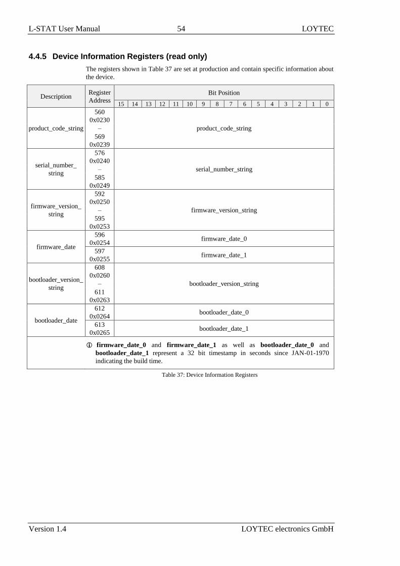
L-STAT User Manual 54 LOYTEC
Version 1.4 LOYTEC electronics GmbH
4.4.5 Device Information Registers (read only)
The registers shown in Table 37 are set at production and contain specific information about
the device.
Description Register
Address
Bit Position
15 14 13 12 11 10 9 8 7 6 5 4 3 2 1 0
product_code_string
560
0x0230
product_code_string –
569
0x0239
serial_number_
string
576
0x0240
serial_number_string –
585
0x0249
firmware_version_
string
592
0x0250
firmware_version_string –
595
0x0253
firmware_date
596
0x0254 firmware_date_0
597
0x0255 firmware_date_1
bootloader_version_
string
608
0x0260
bootloader_version_string –
611
0x0263
bootloader_date
612
0x0264 bootloader_date_0
613
0x0265 bootloader_date_1
firmware_date_0 and firmware_date_1 as well as bootloader_date_0 and
bootloader_date_1 represent a 32 bit timestamp in seconds since JAN-01-1970
indicating the build time.
Table 37: Device Information Registers

L-STAT User Manual 55 LOYTEC
Version 1.4 LOYTEC electronics GmbH
4.4.6 NFC Registers
These registers provide an URL that can be accessed by NFC enabled devices such as smart
phones to get additional information and control of the room automation.
Description Register
Address
Bit Position
15 14 13 12 11 10 9 8 7 6 5 4 3 2 1 0
url_string
1024
0x0400
[http://www.loytec.com] –
1148
0x047C
Up to 248 ASCII character including a string terminator (0x00) can be used. The string
will be converted to a NDEF URI record that is saved on the NFC tag. For further
information on the NFC interface see Chapter 5.
Table 38: NFC Registers

L-STAT User Manual 56 LOYTEC
Version 1.4 LOYTEC electronics GmbH
4.4.7 Value Scaling and Stepwidth
The following Table 39 gives an overview of how Modbus register datapoints (display
values, set points, min., max. and offset values) need to be scaled to achieve the desired
result at the L-STAT display. It also shows which stepwidth is defined for set points.
Physical Value Unit
Modbus Scaling
A*10^B*(raw + C) Set Point Stepwidth Example
A B C raw value displayed value
No Unit - 1 0 0 1 100 100.0
Temperature
(K) 1 -1 -2740 0,5 2975 023.5 °C
°C 1 -1 0 0,5 235 023.5 °C
°F 1 -1 0 1,0 743 074.0 °F
°F dec. 1 -1 0 0,5 743 074.5 °F
Flow
m³/h 1 0 0 1 150 150.0 m³/h
l/s 1 -1 0 0,1 417 041.7 l/s
cfm 1 0 0 1 88 088.0 cfm
Pressure Pa 1 0 0 1 200 200.0
Pa
inWC 1 -3 0 0,01 803 0.803 inWC
Voltage V 1 -1 0 0,1 240 024.0 V
Percentage % 5 -3 0 1 9000 045.0 %
Humidity %RH 5 -3 0 1 9000 045.0 %RH
Amount CO2 ppm 1 0 0 1 550 550.0 ppm
Note that though a display value or a set point would accept values from 0 to 65535 if
unsigned or -32768 to 32767 if signed the value that is displayed is limited to a range from
-999 to 9999 because of the 4 digit display.
When a fixed-point number reaches a certain limit where an overflow occurs the
decimal point is shifted rightwards (e.g. 999.9 → 1000).
Whole number values are preferably displayed with the bigger digits. If an overflow
occurs the number is shifted rightwards (e.g. 999 → 1000).
Table 39: Value Scaling and Stepwidth

L-STAT User Manual 57 LOYTEC
Version 1.4 LOYTEC electronics GmbH
5 NFC
5.1 General Description
The NFC interface of the L-STAT device can be used to get additional information and
configuration options for room automation. The L-STAT will behave like an NFC tag that
can be read by an NFC enabled device. The antenna is located behind the LCD and best
performance is achieved by putting the NFC enabled device right on the front panel glass.
Depending on where the antenna of the mobile device is located the optimal position will be
found by moving the device slowly over the front panel. Best performance can be achieved
by positioning the device in a more or less horizontal position covering the LCD as shown in
Figure 10.
Figure 10: NFC Device Positioning
If the connection is established the NFC field detection bit at the short_pressed Modbus
register at address 1 (Table 7 at Page 26) will be set. In the meantime the NFC enabled
device will read the memory of the tag and will perform an appropriate action. Since a
NDEF URI record is saved at the tags memory (Table 38 at Page 55) the device will ask to
open the defined URL in the browser of the NFC enabled device.

L-STAT User Manual 58 LOYTEC
Version 1.4 LOYTEC electronics GmbH
5.2 Copy the L-WEB Project URL to the NFC Tag Memory
To show an L-WEB project on your mobile device by NFC, simply copy and paste the URL
of the L-Web project to the url_string of Table 38. Note that the mobile device needs
network or internet access to open the URL. Please follow the instructions below.
To Copy a L-WEB Project URL to the NFC Tag Memory
1. Open the web interface of your device
2. Select Project List from the L-WEB menu.
3. Open the desired project in the web browser as shown in Figure 11.
Figure 11: L-WEB Project List
4. Simply copy the URL of the desired project from the browsers address bar and go to
the Modbus Datapoints of the L-STAT device.
5. Open the nfc_string datapoint in the web interface of your device and paste the
L-WEB project URL at the Value field as shown in Figure 12.
6. Click on the Set button to save the string.

L-STAT User Manual 59 LOYTEC
Version 1.4 LOYTEC electronics GmbH
Figure 12: L-STAT NFC String

L-STAT User Manual 60 LOYTEC
Version 1.4 LOYTEC electronics GmbH
6 IR-Remote Control Operation
6.1 General Description
The IR receiver is located behind the front panel glass above the LCD. The L-STAT device
implements the NEC IR protocol compatible with the Apple remote control as displayed in
Figure 13.
Figure 13: Apple Remote Control
Whenever a command gets received the IRC bit at the short_pressed Modbus register at
address 1 (Table 7 at Page 26) is set. The received button code as well as the remote ID can
be read from the ir_remote_control_command register at address 32 (Table 9 at Page 27).
Button Number Description Button Code
1 Center 46
2 Up 5
3 Left 4
4 Right 3
5 Down 6
6 Menu 1
7 Play/Pause 47
Table 40: Apple Remote Button Codes

L-STAT User Manual 61 LOYTEC
Version 1.4 LOYTEC electronics GmbH
6.2 Remote Control Pairing
Each remote control has an ID that is transmitted along with the button code. This ID can be
used to pair a certain remote control with a certain L-STAT device. The ID of the Apple
remote control can be changed by pressing Menu and Center button for at least 6s. This will
increment the ID by one.
The ID of your remote control can be checked by pressing any button and watching the
ir_remote_control_command register in the Web interface as shown in Figure 14 below.
This example shows that the Menu button was pressed on a remote control with the ID 14.
Figure 14: IR Remote Control Command Register
If an L-STAT device gets paired with a certain remote control it will only update the
ir_remote_control_command register and the IRC bit at the short_pressed register when
receiving a command from this remote control.
Pairing can be achieved by pressing Menu and Right button at the remote control for at least
6s while pointing towards the L-STAT device. If pairing worked the secondary display will
shortly show ‘IRP’ (IR pairing). The remote ID will be saved internally and the IRCP flag of
the config_flags register at address 192 (Table 22 at Page 36) will be set.
The pairing can be canceled by either clearing the IRCP flag or by pressing Menu and Left
button for at least 6s. If the secondary display shows ‘IRUP’ (IR unpairing) shortly the pairing
is suspended.
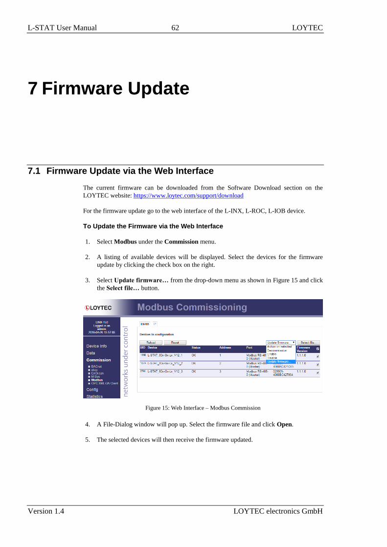
L-STAT User Manual 62 LOYTEC
Version 1.4 LOYTEC electronics GmbH
7 Firmware Update
7.1 Firmware Update via the Web Interface
The current firmware can be downloaded from the Software Download section on the
LOYTEC website: https://www.loytec.com/support/download
For the firmware update go to the web interface of the L-INX, L-ROC, L-IOB device.
To Update the Firmware via the Web Interface
1. Select Modbus under the Commission menu.
2. A listing of available devices will be displayed. Select the devices for the firmware
update by clicking the check box on the right.
3. Select Update firmware… from the drop-down menu as shown in Figure 15 and click
the Select file… button.
Figure 15: Web Interface – Modbus Commission
4. A File-Dialog window will pop up. Select the firmware file and click Open.
5. The selected devices will then receive the firmware updated.

L-STAT User Manual 63 LOYTEC
Version 1.4 LOYTEC electronics GmbH
7.2 Restoring Default Modbus Settings in Bootloader
If something went wrong during the firmware update the device keeps waiting in bootloader
until a complete firmware image was received over Modbus. If also the Modbus settings got
lost a procedure has been implemented in bootloader version 1.2.2 to restore the default
Modbus settings: Parity = None, Baudrate = 57,6kB, Address = 1
To Restore the Default Modbus Settings in Bootloader
1. Unplug the power supply of the device.
2. Install a cable bridge between EB2 and EB3 as shown in Figure 16 below.
Figure 16: Cable Bridge EB2–EB3
3. Plug in the power supply again.
4. A red clock symbol will be displayed:
5. If the cable bridge between EB2 and EB3 gets removed within 10 seconds from now
on, the default Modbus settings will be restored. Otherwise the device will try to boot
up as usual after the timeout has expired.
EB2 EB3

L-STAT User Manual 64 LOYTEC
Version 1.4 LOYTEC electronics GmbH
8 Configuration Backup & Restore
8.1 Configuration Backup & Restore via the Web Interface
For further information on configuration backup and restore via the web interface please
refer to the LOYTEC Device User Manual [2].

L-STAT User Manual 65 LOYTEC
Version 1.4 LOYTEC electronics GmbH
9 Troubleshooting
9.1 Technical Support
LOYTEC offers free telephone and e-mail support for the L-STAT product series. If none of
the above descriptions solves your specific problem please contact us at the following
address:
LOYTEC electronics GmbH
Blumengasse 35
A-1170 Vienna
Austria / Europe
e-mail : [email protected]
Web : http://www.loytec.com
tel : +43/1/4020805-100
fax : +43/1/4020805-99
or
LOYTEC Americas Inc.
N27 W23957 Paul Road
Suite 103
Pewaukee, WI 53072
USA
e-mail: [email protected]
Web: http://www.loytec-americas.com
tel: +1 (512) 402 5319
fax: +1 (262) 408 5238
or
LOYTEC Asia Corporation Ltd.
16F.-3, No. 155, Zhongyang Rd
Xindian District
New Taipei City 23150
Taiwan
e-mail: [email protected]
tel: +886 (2) 8913 7838
fax: +886 (2) 8913 7830

L-STAT User Manual 66 LOYTEC
Version 1.4 LOYTEC electronics GmbH
10 Specifications
10.1 Physical Specifications
Operating Voltage 24 VDC ±10 %
Power Consumption see Table 41
In rush current up to 4A @ 24 VDC
Operating Temperature (ambient) 0C to +50C
Storage Temperature –10C to +60C
Humidity (non condensing) operating 10 to 90 % RH @ 50C
Humidity (non condensing) storage 10 to 90 % RH @ 50C
LCD Backlight Lifetime 50,000 hours
Enclosure 94.5 x 110 x 19.5 (W x H x D)
Environmental Protection IP 30 (enclosure)
Installation Europe: switch box Ø 60mm
US: switch box 4” x 2”
LCD brightness LSTAT-800-Gx-Lx &
LSTAT-801-Gx-Lx LSTAT-802-Gx-Lx
100% 0.8W 0.93W avg., 1.8W max.
0% 0.09W 0.22W avg., 1.1W max.
Table 41: Power Consumption

L-STAT User Manual 67 LOYTEC
Version 1.4 LOYTEC electronics GmbH
Following Table 42 should provide support for dimensioning of an installation and the
power supply. For each device type there is a listing for up to 16 devices of the maximum
possible cable length and the resulting power loss on the cable for different supply voltage
levels. Together with the power consumption of the devices one can calculate the required
power of the power supply.
Conditions of the Installation Number of Devices
1 2 3 4 5 6 7 8 9 10 11 12 13 14 15 16
L-S
TA
T 8
00/8
01
maximum power
consumption of devices [W] 0,8 1,6 2,4 3,2 4,0 4,8 5,6 6,4 7,2 8,0 8,8 9,6 10,4 11,2 12,0 12,8
24V
DC
max. Cable
length [m]
for 0,5mm² 1.620 810 540 400 320 270 230 200 180 160 140 130 120 110 100 100
for 1,0mm² 3.250 1.620 1.080 810 650 540 460 400 360 320 290 270 250 230 210 200
max. Power loss
on cable [W] 0,2 0,4 0,6 0,9 1,1 1,3 1,5 1,7 1,9 2,1 2,3 2,6 2,8 3,0 3,2 3,4
20V
DC
max. Cable
length [m]
for 0,5mm² 1.260 630 420 310 250 210 180 150 140 120 110 100 90 90 80 70
for 1,0mm² 2.530 1.260 840 630 500 420 360 310 280 250 230 210 190 180 160 150
max. Power loss
on cable [W] 0,3 0,5 0,8 1,0 1,3 1,6 1,8 2,0 2,3 2,6 2,9 3,1 3,3 3,6 3,7 3,8
L-S
TA
T 8
02
maximum power
consumption of devices
[W]
[W] 1,8 3,6 5,4 7,2 9,0 10,8 12,6 14,4 16,2 18,0 19,8 21,6 23,4 25,2 27,0 28,8
24V
DC
max. Cable
length [m]
for 0,5mm² 720 360 240 180 140 120 100 90 80 70 60 60 50 50 40 40
for 1,0mm² 1.440 720 480 360 280 240 200 180 160 140 130 120 110 100 90 90
max. Power loss
on cable [W] 0,5 1,0 1,5 1,9 2,3 2,9 3,3 3,9 4,4 4,7 5,3 5,8 6,3 6,5 6,6 7,8
20V
DC
max. Cable
length [m]
for 0,5mm² 560 280 180 140 110 90 80 70 60 50 50 40 40 40 30 30
for 1,0mm² 1.120 560 370 280 220 180 160 140 120 110 100 90 80 80 70 70
max. Power loss
on cable [W] 0,6 1,2 1,7 2,3 2,8 3,3 4,1 4,7 5,0 5,7 6,3 6,6 6,7 8,2 7,9 9,4
Table 42: Cable Length and Power Loss on Cable

L-STAT User Manual 68 LOYTEC
Version 1.4 LOYTEC electronics GmbH
10.2 Sensor Specifications
Ambient Temperature Sensor type: CMOS
range: -40 – 125 °C
resolution: 0.1 °C
accuracy: ± 0.5 °C (5 – 60 °C)
Relative Humidity Sensor type: capacitive
range: 0 – 100 %R.H.
resolution: 0.1 %R.H.
accuracy: ±2 %R.H. @ 25 °C, 20 – 80 %R.H.
±3 %R.H. @ 25 °C, 0 – 20 %R.H. &
80 – 100 %R.H.
CO2 Sensor type: NDIR
range: 0 – 2000 ppm
resolution: 1 ppm
accuracy: ±30 ppm or ±3 % of reading
warm up time: < 2 min (operational),
10 min (max. accuracy)
self calibration:
The sensor will perform a self calibration routine
within the first 24 hours of continuous operation.
After calibration has finished the sensor will
operate at the defined accuracy.
The sensor also remembers the lowest CO2 levels of
the last 14 days to compensate gradual sensor drift.
Therefor it has to be guaranteed that CO2
concentration regularly drops to outside background
levels. Usually this takes place when a building is
unoccupied for 4 to 8 hours a day.
Occupancy Sensor max. range: 5 m
detection zones: 64
opening angle: 94° H, 82° V (see Figure 17)
temperature difference to background: 4°C
TOP-View: SIDE-View:
Figure 17: Occupancy Sensor Opening Angle

L-STAT User Manual 69 LOYTEC
Version 1.4 LOYTEC electronics GmbH
Infrared Receiver protocol: NEC
carrier: 38 kHz @ 950 nm
Apple remote control compatible

L-STAT User Manual 70 LOYTEC
Version 1.4 LOYTEC electronics GmbH
11 References
[1] L-INX Configurator User Manual, LOYTEC electronics GmbH
[2] LOYTEC Device User Manual, LOYTEC electronics GmbH
L-STAT User Manual 71 LOYTEC
Version 1.4 LOYTEC electronics GmbH
12 Revision History
Date Version Author Description
2015-12-09 1.0 HG Initial Manual Version
2016-02-25 1.1 HG Added comment for cleaning mode at MENU-Button
description, revised description of 3.2.2 Operating Modes,
extended description at 4.1 Introduction, revised Figure 7,
changed size of Figure 8, changed layout of Table 36,
added Table 42 and description for cable length and power
supply dimensioning, extended description of CO2 sensor
self calibration algorythmus, correction of typing errors
2016-05-25 1.2 HG “What´s new” Chapter added, “Configuration Backup &
Restore” Chapter added, Minor mistakes corrected,
description for temperature sensor on EB3 added at
Section 3.1, Table 4 reworked, Figure 5 and description
added Section 3.2.3, description for external temperature
sensor added below Table 10, Table 12, Table 13 and
Table 20 reworked, occupancy_timeout description
corrected at Table 21, SDSV flag added and descriptions
revised at Table 22, descriptions added at Section 4.4.3,
Table 23 info text reworked, pictures added at Table 36,
description for Table 39 modified, updated Figure 15
2016-10-31 1.3 HG Description at DIRECT_ACCESS-mode added at Table 4,
Display Auto Shuffle added at Table 5, description of
Table 7 modified, change flag for display_unit added at
Table 8, DAS flag and description added at Table 20, “°F
dec.” unit added at Table 28 and Table 29, text modified at
Page 45, example configuration for fan stage set point
added at Table 31, light_up and light_down default print
added at Table 36, “°F dec.” unit added at Table 39, added
Section 7.2
2017-01-18 1.4 HG Description for new feature (loading factory default values)
added at Section 3.2.4 and 3.2.5