Embed Size (px)
Citation preview
Digital Video PatternGenerator
DVPG
Op
erat
ion
Man
ual
1
Contents
2lareneG.1
3Standard Composition.2
4Main Features.3
5Installation.4
8Function and Operation.5
11Speci�cations.6
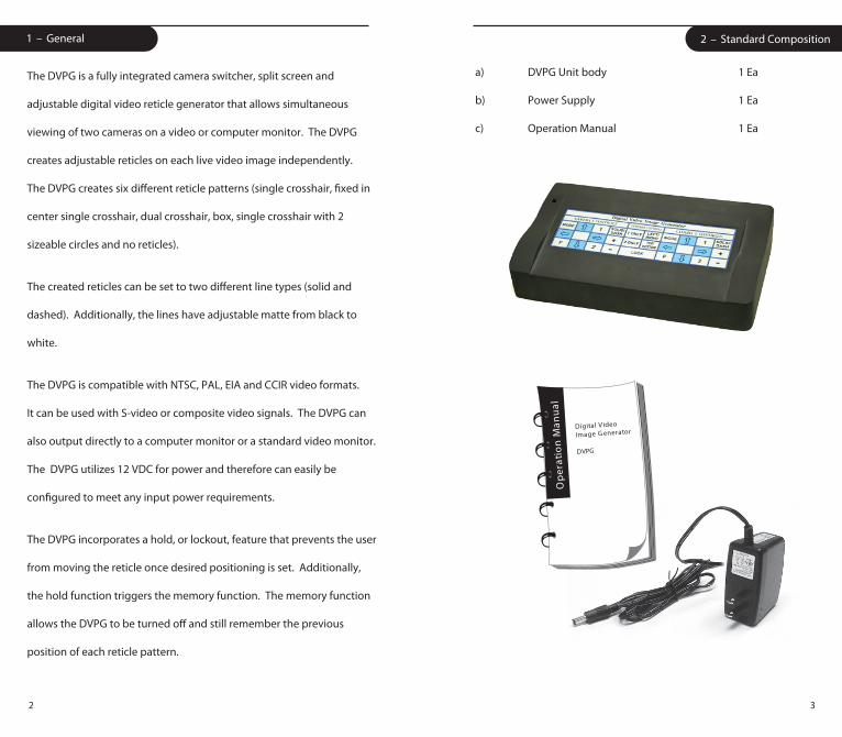
a) DVPG Unit body 1 Ea
b) Power Supply 1 Ea
c) Operation Manual 1 Ea
32
2 – Standard Composition1 – General
The DVPG is a fully integrated camera switcher, split screen and
adjustable digital video reticle generator that allows simultaneous
viewing of two cameras on a video or computer monitor. The DVPG
creates adjustable reticles on each live video image independently.
The DVPG creates six di�erent reticle patterns (single crosshair, �xed in
center single crosshair, dual crosshair, box, single crosshair with 2
sizeable circles and no reticles).
The created reticles can be set to two di�erent line types (solid and
dashed). Additionally, the lines have adjustable matte from black to
white.
The DVPG is compatible with NTSC, PAL, EIA and CCIR video formats.
It can be used with S-video or composite video signals. The DVPG can
also output directly to a computer monitor or a standard video monitor.
The DVPG utilizes 12 VDC for power and therefore can easily be
con�gured to meet any input power requirements.
The DVPG incorporates a hold, or lockout, feature that prevents the user
from moving the reticle once desired positioning is set. Additionally,
the hold function triggers the memory function. The memory function
allows the DVPG to be turned o� and still remember the previous
position of each reticle pattern.
Digital Video
Image G enerator
DVPG
Op
erat
ion
Man
ual
54
3 – Main Features
• Split screen and switcher capability for two cameras (Horizontal or Vertical split).
• Can be used with single camera.
• Six built in reticle patterns (single crosshair, fixed in center single crosshair, dual crosshair, box, single crosshair with 2 sizeable circles and no reticle)
• Two built in line types (solid, dashed).
• Lines have adjustable matte from black to white.
• Convenient “Hold” or lockout capability
• Digital circuity for maximum stability
• Digital memory of reticle position and line type when powered off
• Accommodates both composite and S-video
• Outputs directly to a standard video monitor or directly to a computer monitor
• Operates in Color or B & W
• External sync is provided
• NTSC, PAL, EIA and CCIR compatible
4 – Installation
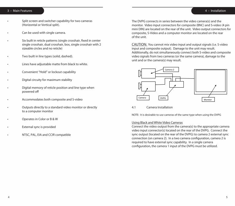
The DVPG connects in series between the video camera(s) and the monitor. Video input connectors for composite (BNC) and S-video (4 pin mini DIN) are located on the rear of the unit. Video output connectors for composite, S-Video and a computer monitor are located on the rear of the unit.
Camera 1
DVPG Monitor
Camera 2
CAUTION: You cannot mix video input and output signals (i.e. S-video input and composite output). Damage to the unit may result. Additionally, do not simultaneously connect both S-video and composite video signals from two cameras (or the same camera), damage to the unit and or the camera(s) may result.
4.1 Camera Installation
NOTE: It is desirable to use cameras of the same type when using the DVPG
Using Black and White Video CamerasConnect the video output from the camera(s) to the appropriate camera video input connector(s) located on the rear of the DVPG. Connect the sync output (located on the rear of the DVPG) to camera 2 external sync connection (on camera 2). In a two camera configuration, camera 2 is required to have external sync capability. In a single camera configuration, the camera 1 input of the DVPG must be utilized.
76
Installation Installation
Using Color Cameras with composite (BNC) output Connect the video output from the camera(s) to the appropriate camera video input connector(s) located on the rear of the DVPG. Connect the sync output (located on the rear of the DVPG) to camera 2 external sync connection (on camera 2). In a two camera con�guration, camera 2 is required to have Gen Lock capability or external sync capability with phase control adjustment. In a single camera con�guration, the camera 1 input of the DVPG must be utilized. If a camera with external sync and no phase control adjustment is utilized in the camera 2 position, the color may not be correct.
Using Color Cameras with S-Video (4 pin DIN) outputConnect the video output from the camera(s) to the appropriate camera video input connector(s) located on the rear of the DVPG. Connect the composite video output (located on the rear of the DVPG) to the camera 2 external sync connection (on camera 2). In a two camera con�guration, camera 2 is required to have Gen Lock capability or external sync capability with phase control adjustment. In a single camera con�guration, the camera 1 input of the DVPG must be utilized. If a camera with external sync and no phase control adjustment is utilized in the camera 2 position, the color may not be correct.
4.2 Monitor Installation
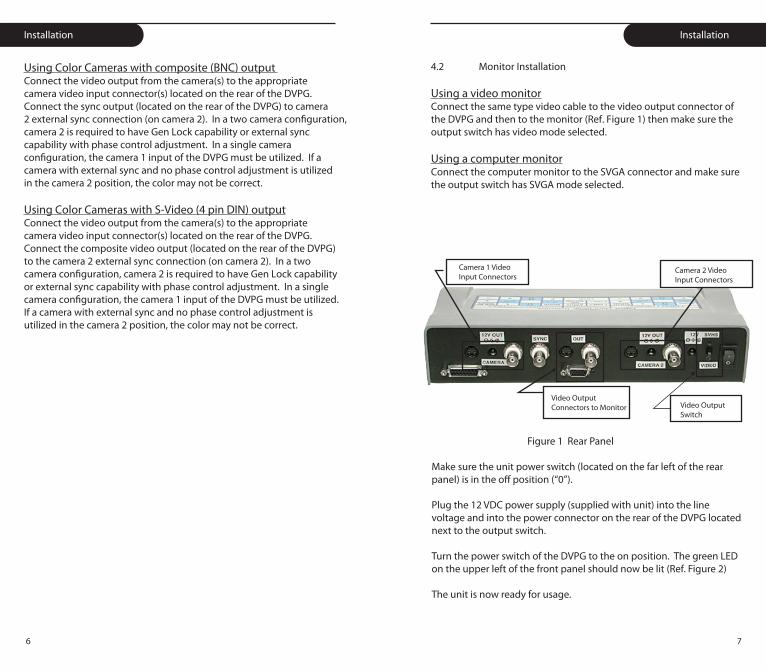
Using a video monitorConnect the same type video cable to the video output connector of the DVPG and then to the monitor (Ref. Figure 1) then make sure the output switch has video mode selected.
Using a computer monitorConnect the computer monitor to the SVGA connector and make sure the output switch has SVGA mode selected.
Camera 1 Video Input Connectors
Camera 2 Video Input Connectors
Video OutputConnectors to Monitor Video Output
Switch
Figure 1 Rear Panel
Make sure the unit power switch (located on the far left of the rear panel) is in the o� position (“0”).
Plug the 12 VDC power supply (supplied with unit) into the line voltage and into the power connector on the rear of the DVPG located next to the output switch.
Turn the power switch of the DVPG to the on position. The green LED on the upper left of the front panel should now be lit (Ref. Figure 2)
The unit is now ready for usage.
98
5 – Function & Operation 5 – Function & Operation
5.1 “Hold” Lockout Mode
Upon initial startup, the DVPG is defaulted to “HOLD” or lockout mode.
This is indicated on the monitor in the upper left corner. When the
“HOLD” is present, all keyboard functions are locked out.
To remove the unit from lockout mode, press and hold the “LOCK”
button until the indicator in the top left of the monitor changes from
“HOLD” to “1”. Keyboard function is now restored to the unit.
Once proper position of a reticle is established, it may be desirable to
prevent the reticle from accidentally being moved; this is
accomplished by placing the unit back in lockout mode.
To place the unit in lockout mode, press and hold the “LOCK” button
until the indicator in the top left of the monitor changes from “1” or
“2” to “HOLD”. All keyboard functions are now locked out.
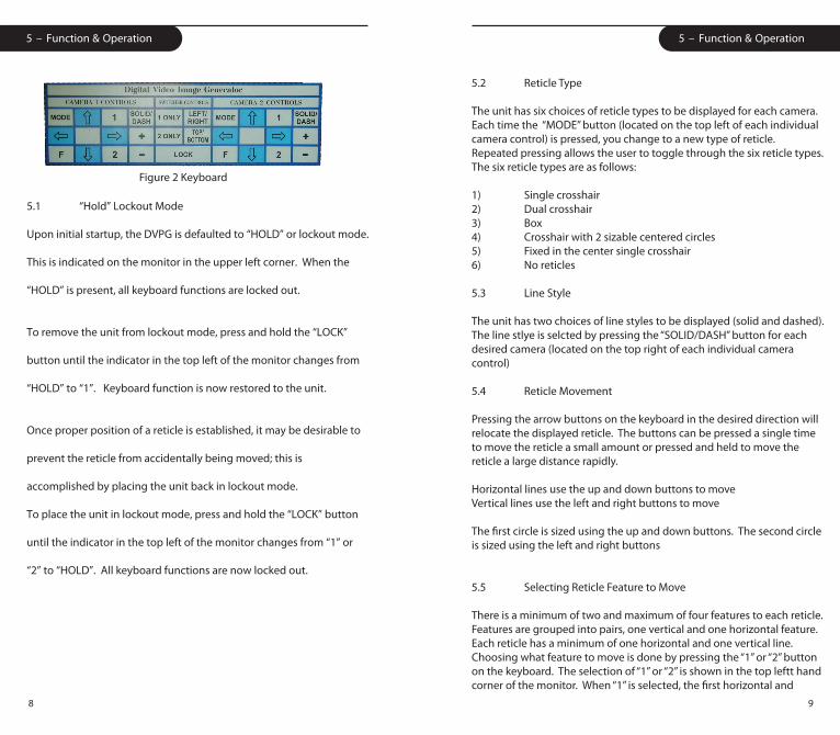
Figure 2 Keyboard
5.2 Reticle Type
The unit has six choices of reticle types to be displayed for each camera. Each time the “MODE” button (located on the top left of each individual camera control) is pressed, you change to a new type of reticle. Repeated pressing allows the user to toggle through the six reticle types. The six reticle types are as follows:
1) Single crosshair2) Dual crosshair3) Box4) Crosshair with 2 sizable centered circles5) Fixed in the center single crosshair6) No reticles
5.3 Line Style
The unit has two choices of line styles to be displayed (solid and dashed). The line stlye is selcted by pressing the “SOLID/DASH” button for each desired camera (located on the top right of each individual camera control)
5.4 Reticle Movement
Pressing the arrow buttons on the keyboard in the desired direction will relocate the displayed reticle. The buttons can be pressed a single time to move the reticle a small amount or pressed and held to move the reticle a large distance rapidly.
Horizontal lines use the up and down buttons to moveVertical lines use the left and right buttons to move
The �rst circle is sized using the up and down buttons. The second circle is sized using the left and right buttons
5.5 Selecting Reticle Feature to Move
There is a minimum of two and maximum of four features to each reticle. Features are grouped into pairs, one vertical and one horizontal feature. Each reticle has a minimum of one horizontal and one vertical line. Choosing what feature to move is done by pressing the “1” or “2” button on the keyboard. The selection of “1” or “2” is shown in the top leftt hand corner of the monitor. When “1” is selected, the �rst horizontal and
1110
5 – Function & Operation 6 – Speci�cations
vertical feature pairs may be moved using the appropriate arrow buttons. When “2” is selected, the second pair of horizontal and vertical features may be moved using the appropriate arrow buttons. The exceptions to this are the single crosshair reticle (there is no second feature pair) and the single crosshair with 2 circles. When “2” is selected, the �rst circle of the single crosshair with 2 circles reticle can be sized using the up and down arrows. The second circle of the single crosshair with 2 circles reticle can be sized using the left and right arrow buttons.
5.6 Memory Function
The memory function allows the user to return to the desired reticle position and line type after the unit has been powered o�. To enable memory, the user places the unit in “Hold” Lockout Mode prior to powering the unit o�. See section 5.1 for instructions to place the unit in “Hold” mode.
5.7 Switcher and Split Screen Control Functions
The switcher and split screen functions allow the user to view two cameras on the screen simultaneously or individually. To enable the switcher and split screen functions, the unit must be removed from lockout mode (See section 5.1). To view camera 1 only, press the “1 ONLY” button (located in the center of the DVPG keyboard). To view camera 2 only, press the “2 ONLY” button (located in the center of the DVPG keyboard). To view the cameras simultaneously split vertically, push the “LEFT/RIGHT” button (located in the center of the DVPG keyboard). To view the cameras simultaneously split horizontally, push the “TOP/BOTTOM” button (located in the center of the DVPG keyboard).
Video
• Signal: .7-1.4vp-p @75 ohms (NTSC, PAL, EIA, CCIR)• Video Input: RS170, Composite and S-video• Video Output: Unity gain, loop through, or SVGA• Power Input: 12 VDC regulated
Mechanical
• Dimensions: (w) x (h) x (l) 10. 50” x 2.00” x 6.50” (includes rear connectors) (w) x (h) x (l) 26.7 cm x 5.1 cm x 16.5cm (includes rear connectors)• Weight: 1.5 lbs.
Power
Specify 110 or 220VAC, 110VAC standard (if not specified).
5653 Stoneridge Drive #101Pleasanton, CA 94566
Phone: 925-251-9030 Fax: 925-251-07041-888-414-0789 (toll-free)
Revision 00112/15/08