Embed Size (px)
Citation preview

,.
TECHNICAL !WMORANDTJMS..
~:~TIO:JA~“AD.V’~soAYCOMMITTEE Fi)R AEP.ONAUTICS
- .. —=---
~0. 976
“;A,,,.“
PRESi13TT AND. J!’UTTJREPROBLEMS 03’ AIRPLAN13 Propulsion
By J. Ackeret
Schweizervol. 112, No.
*
--—
Bauzeitung1, July 2, 1938
,.
l?I--—-
+-;..
,,,, ,1..
,... .,,.., . . . . . .,, ,!. .,.,., ,.” “
.
,.,. WashingtonMay 1941
(.,
l...–- -.— --- .— ....— /—.—
Illlllllllllllumlwilllllllllllllll31176014407234. . . —..
I
,
NATIONAL ,ADVISORY COMMITTEE
---— ____
‘TECHNICAL MEMORANDUM
I’QR AEROITAUTIC.S
NO . 976
.—-— ——
PRESENT AND FUTURE PROBLEMS
OF AIRPL.4NE PROPULSION*
By J. Ackeret,’
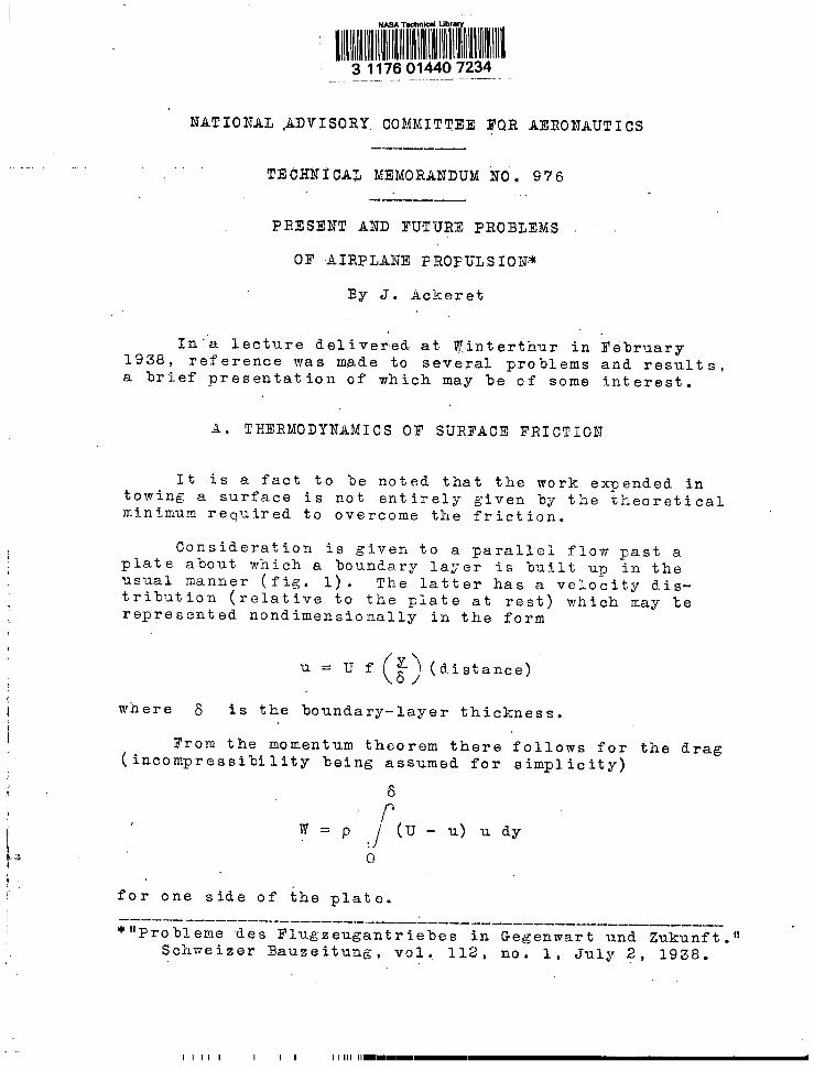
In”a lecture delivered. at ~interthur in X’ebruary1938, reference was made to several problems and results,a brief presentation of wk.ich may be of some interest.
A. THERMODYNAMICS OF SURFACE FRICTION
It is a fact to be noted that the work expended intowing a surface is not entirely given by the tl,eoreticalminimum required to overcome the friction.
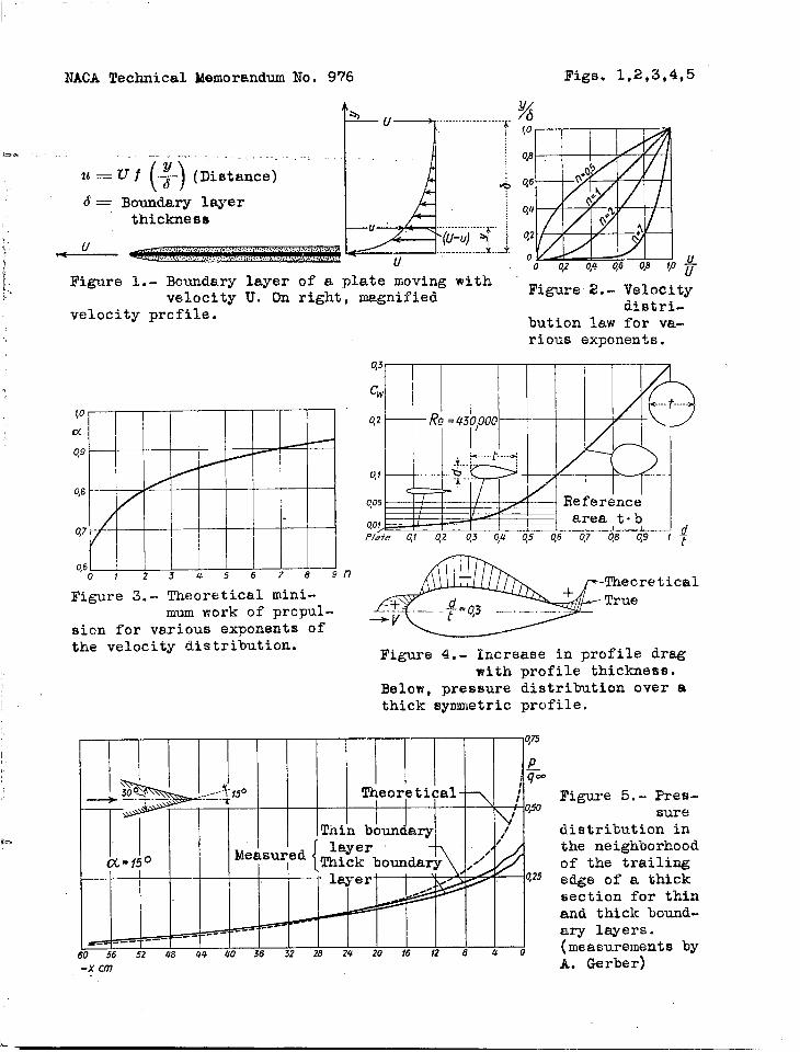
Consideration is given to a parallei flow past aplate about which a boundary layer is built u~ irltheusual manner (fig. 1) . The latter has a velo~ity dis-tribution (relative to the plate at rest) which may berepresented nondimensionally in the form
()(u=uf 3/ ‘iStance)iI w“here 6 is the boundary-layer thickness.I1 From the momentum theorem there follows for the drag/. (incompressibility being assumed for simplicity)j1
~
8
W=p rJ (u -u)udy
/&
\
@
1,for one side of the plate.———_——__—___— ______ _____ ———— ____________________*“Probleme des Flugzeugantriebes in Gegenwart und Zukunft.”
Schweizer Bauzeitung, vol., 112, no. 1, July 2, 1938.
11111 I II I 1111 llmmmmI—l— *
. . . . . . ..-,
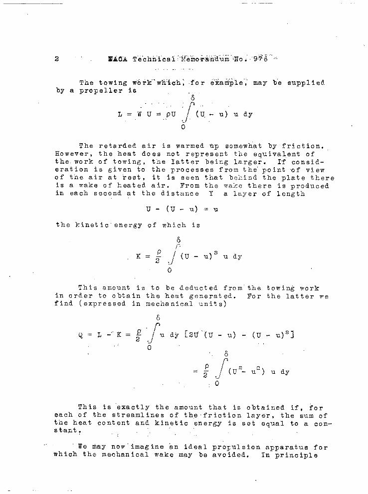
The towing wbrk””wh:ich~ -f”or e’~a~~le”;’may b’e suppliedby a propeller is
-8.,. .,,.L=lf U=PU r~,(u.- U) ‘U dy.>
0
The retarded air is warmed tip somewhat by friction.However, the heat does not represent tlie equivalent Of
the. work of towing, tlie latter being larger. If ~on~id-eration is given to the processes from the” ”point of viewof t-ne air at rest, it is seen that hekind the plate thereis a make of heated. a5.r. Prom the wake there is producedin each second at the distance Y a lzyer of length
u- (U-u)=u
the kinetic” energy of which is
6,..,,.
/{p!
~ ‘= 5- ,OJ
U-2udy11)
o
This amount is to be deducted from” the towing workin order to obtain the heat generated. For the latter wefind (expressed in mechanical units)
~ = ~ - K=:- ru dy [2U’’”(U- U) - (U - U)2]
,,’ 0“6
,0
This is exactly the amount that is obtained. if, foreach of the streamlines of th,efriction layer, the sum ofthe heat content and kinetic energy is set equal to a con-stant . ,’..
.. We fray nom’imagine an ideal profusion apparatus forwhich the mechanical wake may be avoided. In principle

NACA Technical Memorandum
each part of the boundary lay_er must,-. ““full .velticity “I?. Th”er-modynamically
No. 976 3
be Prought up to thethis means the a-
voidance of all macroscopic motion in the wake, -onlythatportion of the. work being unavoidable which is e.ctuallyirreversible. The minimum of the propulsive work there-fore may be coasid.ered as the heat output
which may be directly verified as the necessary work ex-penditure for the production of the complete velocity Uat constant pressure starting from any velocity u.
n -r
The ratio.&
a,= ~= 1 - ~L
is thus a measure of the
gain that such a control of the boundary layer would makepossible. For the exponential law
u.=(Y);u ‘.8)
(fig. 2) there is easily obtained
~=, n + 2———_.n+3
(fig. 3).
B. APPLICATION Ol? THICK WIIJG SE,CTIONS
It is.well known that thick profiles offer more re-sistance than thin ones. At the present time, the thick-ness chord r!atics are usually about 12 to 16 percent whilehigher oaes are practically excluded. Figure 4 shows thenormal increase in drag with thickness. What is this dueto? The drag may be decomposed into a component due tothe tangential surface forces and one dePending on thenormal pressures. It is quite certain” that for very
.-

4. . ..
NACA T echn icat }~ehora”n”dli’m”No .‘“’”’676
. . .,.blunt bodies”’this second ,,cdmp’o~ne,n~t”’”of.the’ ‘dra~ co”n’$ributes
the most. In, the case of” ,@ediil.rn.,}~ikknes”s, :(foi ~?ample,.25 to .30 percent) the’ answ,er is” less certain. ‘The results,’of measurements show that’ the p,ressure dr’ag,,predominates.At the trailing edge, the$e ‘is “a theoret.i.?al ri~”e in”~res-sure up to full dynami’c pressure; actually onl Y a’ frac-tional part of this pressure rise occurs and hence a drag.The low pressnre is due to the fact that the boundarylayer thickens very rapidly t~ward the trailing edge andthe flow there%y is less deflected. If it were possibleto make the boundary layer %efore entry into the pressure-rise zone very thin, there would be a closer approach tothe theoretical curve. By increase of the loundary-layerthickness through artificial roughness, a fllrtile’rimpair-ment is, actually observed (fig. 5) ; by suction of the
boundary layer, “an improvement (fig. 6) .
With suitable design of the suction slots the re-quired low pressure is quite small. * The slot ‘shapespreviously used were less favorable in this respect.Another solution would be the addition of ,kinetic energyto the boundary layer directly by means of blowers. Itis possible to use for this purpose old type’s of blowers(Mortier) which, with present-d,ay improvements, may bemade to give entirely useful efficiencies. The boundary-layer air enters and leaves the wheel radially and impartsto it a primary velocity which is desirable. The dimen-sions required are surprisingly small (fig. 7).
c. SPECIAL APPLICATIONS OT CONTROLLABLE PROFELLERS
a) For Accelerating Gliding Flight
In coming down from altitude the pilot cuts off thegas and hri.ng.sth.-een,gin.es..to idling. The flight pathreceives “an inclination ~ downwards, the “drag W beingbalanced by the component of the weight G along theflight path, G. ,sin~ ..=W,, negl.ect.ing the effect of thepro’pe.ller. If in this ‘.&Onditi’on,”fu’11 throt.tle ’is appliedand, no change i’smade-in the ‘pro,p.e.ller.pi,tch,,the engine,.would be, dangero”usly”lzo,aded. ..If!,.however, it is possible... ,.-—___—— ___-—_ __,-— +—.--—+—+-—-.—-—-———-———----——-—-—-—————+- .
,* . ..A-more de$ailedre~ort on the boundary suction experi- “
men.ts ’by Al”.fr.“Gerber..will soon appear .in th:e Reportsof the Xns’ti.tut”e.for Aerodynamics. .

NACA Technical Memorandum N,o. 976 5
,.. ,. —- greatly “to ixicrease “’the’p’i’tchlthe’ engi’ne, running at full
throttle to,rque, may be kept down to normal rotationalspeed. Then the velocity receives very large increments..The propeller efficiency is still quite gGod at the. highpitches, and the cooling effectiveness at the high speedsis more than sufficient so that the cooiing flaps may bepractically closed, The dia.grarnof forces is ,snown onfigure 8. To the propulsive component G sinq there isnow added the force S by which the increased drag dueto the high velocity can be.overcome. Figure 9 shows anexample of the relations to be expected. The possiblesteady flig”ht speeds have been’Plotted for differentflight path inclinations- At greater fl,ight altitude thevalues reach 800 kilometers per hour. It may be addedthat the effect Of the compressibility should make itselffelt so that these values may become smaller. Actually,a further steady flight is,,not yossible because of theshortness of the path, Furthermore, t-he denser. air layersin whit-h the velocity again decreases, are soon reached(fig. 10). .
h) For Decreasing the ‘Length of Landing Run
If the propeller is rotated toward small pitches, asharp braking action re,sult.s. The curves of figure 11show, in nondimensional form, the variation in thrust forvarious flight speeds at fixed. pitch. Starting from highspeed, a maximum of 50° rotation is necessary which can bepractically performed immediately uFon touching the
1 ground . It is possible, for example, to shorten the land-ing run by less than one half, the retardation takingf
\ place without a “higher stressing of the wheel brakes asin the case of a very sharply braked al.~tomobile (fig. 12) .?$or the practical application of this very useful possi-
~ bility for our terrain, there are still a numker of ques-/ tions to be answered, such.as controllability on theI ground, etc. Electrical operation of the pitch control
seems hardly possible since a very ,high-power output isrequired for a short period, and hydraulic methods are tobe preferred: The Escher Wyss company has recently put
E, . out a very elegant hydraulic hub’design””which makes pos-sible large changes in pitch (fig, 13) .
,.
Do GAS TURBINES FOR”AIRCRAI’T
Today, the gas ‘turbine is finding application forthe utilization of the exhal.~.stgases of airplane engines

. .6 NACA Technical Memorandum No . ’976
and””for supercharger driv”e.’ ?’h’e”question arises whetherdirect gas-tuibi~e dr~”ve withoii’~,ariyrecipr,ocat~.ng engineis f“easible. It is clear that ”%he gas turbine will findapplication a& a“~tationar,y unit without consideration ofstructural weight, etc. The application to, the airplaneoffers a ,number of special difficulties. On the otherhand , even for the airplane, a part of the gas turbineprocess is now finding application. In “gen~r’al, the gasturbine problem is considered as a question of strengthof material, but it can be sho’wn that it is just as muchan aerodynamic’ problem. If the entropy diagram of asimple constant-pressure gas-turbine process. is consid-ered, then very good compressor” and turbine efficienciesare obtained with the present assumptions of extreme butnot impossible tenlperatures (fig. 14). In particular,the method of regeneration, i.e., exchange of heat be-tween the” exhaust gases leaving the turbine and the ,com-bustion air leaving the compressor, ka.s a very favorableeffect. In figure 14, for equal temperature range and asomewhat lower compression ratio, regeneration withoutloss has been assumed. Naturally, the losses to be ac-counted for are greater, the lighter and more compact the “regenerator is iiesigried. It is of interest to note thatthe turbine lossei are partially compensated for by thesmaller ‘neat expenditure. As may be readily computed,the efficiency Of the ’gas-turbi~e process ~~ith completeregeneration is
where ~t”$ ~K are the adiabatic efficiencies of the tur-
bine ‘and compressor and $ is the temperature ratio of ‘the adiabatic compression. With zero 10ss regeneration,a value of d near one is favorable, but this means alow compression ratio. For the limiting case nt = qK = 1
there is then obtained exactly the Carnot efficiency..
Because of the pro’blem of weight, it is questionablewhether regenerators, which must be provided with largesurfaces , can be considered for airplanes. For futurestationary installations, however, there is no questionthat regeneration will be the method used for raising theefficiency without excessive temperatures. On figure 14,left, the efficiency has been computed as 32.6 percent
,, . . .-.

NA!X Technical Memorandum No. 976 7
. ....(T~in is very” favorable at high altitude) . In practice,
shout 30 percent would. be obtainable. Is it “possible todesign compressors with t15-percent and tllrbiilkswith 90-percent efficiency (referred to adiabatically)? Any con-siderable progress must occur at t-ne expense of the str~~c-tural weight; for, in spite of the relatively small heatdrops, very many stages must, be employed in order to oh-taiil a system of blades without large curvatures. A con-sideration of the losses in a cascade systerl of airfoilss“hows that the blade losses alone make quite good effi-ciencies necessary. Considering the velocity and forcediagrams (fig. 15) , the “stage efficiencies may, with goodapproximation, be given by
~ -1——————— _______ *______________
‘=wCOt (Ct~- ~1) + cot (p’@- Pa)
where
and
If PI = P2 = p, the 10SS may be approximated by
I
ar.d 6min. = 4P90pt “

‘“”—--- I
. .... . . ..’. .... . . .
8 NACA Technical Memorandum No. 976
,“’
If tan-p is 2 percent .-in favoyabie cases (small~ blade curvatures) i 1 percent, - then wheel efficiencies ofalove 90 percent are obtained. Careful detail construc-tion of gaps, bearings, etc~ , should make possible, alsoin the case of ‘smaller units, efficieficies not below 90percent. It mu,st be remembered that the ‘actual impeller ‘efficiencies for Kaplan tur?)ines reach 96 to 98 ‘percentand f.~urtbl”ermore,that the frj.ction rele.tiorls at the blades!also for small Reynolds num-Ders, need not be less favor-able than for very large Re~:riolds numbers. From a con-sideration of figure 16, the following may be concluded:In the case of thin, lightly l,oad”edsections, which behavevery much like flat plates, a minimum for the drag is ob-tained in the region wi~ere the lamiriar layer extends tothe profile trailing edge. Since there is a pressure drop,it is entirely possible, for small blade curvature, to ex-tend the laminar flow condition to the higher Reynolds nurn-lers. Extremely favorable vaiues would then be obtained.At t“he present time, tests are being conducted which in-dicate this behavior for smooth plates in accelerated flow.It mnst be added that the frictional drag depends verymuch on the degree of turbulence of the flow. T“his tur-bulence for high impeller speecls may be unusually low.Certainly, a large+mount of ~ork is still to be done be-fore a practical airplane gas turbine is created. Itwould be reasonable not ‘to ma’ke the weig’nt req-airementstoo stringent at first. It is then possible to obtaingood designs both from the viewpoints of strength and aero-dynamics. It ,is to be expected that the factory processeswith regard to precision of design, surface- smoothness con-trol of material, etc., should not be below the usualstandard in engine construction. It j.s to be remembered,however, that the present -day steam and gas turbines arestill quite far from having attained this e.ccuracy.
Figure 17 shows that the present Kaplan turbine at-tains an incomparably higher degree of fineness than anormal steam turbine. All clearances are relativelysmaller, all surfaces smoother, irregularities in theflow are much fewer. The development of aircraft will,before long, make necessary very,powerful power plantswhich will be required to deliver full output also at thehigher altitudes. Here, the turline may kring about arevolutionary change and t-hrough ibs ,.noiseless, smoothoperation (which among other advantages makes possible theapplication of welded hollow propellers) will also increasethe comfort of the passengers.
Translation by S. Reiss,National Advisory Committee for Aeronautics.
NACA Technical Memorandum No. 976 Figs. 1,2,3,4,5
L ,,—.. ...................~
I“
‘i.,.-. —.. . . . . . . . .. . . .. .. . . .,
()u=uf + (Distance)
“A&
d= Bo~dary layerthickness
1+ u
Figure Boundaryvelocity
layerU. On
of a plate znovingwithright, magnified
velocity profile.
lo
aq9
/ ~
- ~
0,8 -
q7
0,6of23a56 789
Figure 3.- Theoretical znini-mum work of propul-
sion for various exponents ofthe velocity distribution.
n
Figure 2.- Velocitydistri-
bution law for va-rious exponents.
Cw i I I
q2
0,1
qos 1 1! 1 /I *ence1 I 1 1/ -Y 1
area t-bPlife Qi Q2 ~3 ~4 ~5 ~6 ~7 ~8 L79 ,$
TheoreticalTrue
+-v
Figure 4.- Increase in profile dragwith profile thickness.
Below, pressure distribution over athick symmetric profile.
n q75
&
“ ‘+ ‘-’-’:’50
; q-Theoretical-\
j’0>0
Thin boundary f
{
,/
cf”=f50Measured ~;;~bom~ ~ ,.~’
layer-// qzs
— .------- / --------- --------
6056SZ06~o@Je JlzaZQzO~elza 40-x cm
Figure 5.- Pres-sure
distribution inthe neighborhoodof the trailingedge of a thicksection for tk.inand thick bound-ary layers.(measurementsbyA. Gerber)

II ,.
NACA Technical Memorandum No. 976
64 56 48 40.
II-0,4
-0,6
“,-
32 24 16 8 0
Figs. 6,7
Figure 6.-Pressure
distributionwith boundarylayer suctionfor vkriomdegrees of suc-tion. Top left,energy distri-bution in thebcundary layerregion behindthe suctionslot. c
Pis the
necessfirypres-sure differencefor the suctionas ccmqmred withthe pressurewithout stictionin the region ofthe suction slot,referred .~othetotal energy ofthe air. c isa measure ?crthe suctionquantity,
I
55 m/s referred to dynamic pressure ofperipheral velocity.~ discharge
ocity, diameter, andwidthof impell-coefficient referred to peripheral
er. For comparison are given the correspond-ing dotted curves for a usual centrifugal olow-
Figure ‘?,-Uprwr left,
Mortier blowerwith radialpassage. Right,characteristicsof Mortierblower withaccount takenof diffuserlcsses.~ pres-sure coefficient
er. ‘Below, Mortier blower for accelerating theairfoil boundary leyers, drawn for a thick profile of about 6 m chord.
l– .—

I—
>.
NACA Tachnical Memorandum No. 976 Fif+. 8,9,10,11
.W - Vkm/h(#~ $’ ~+&ifl “=
.vl—~
IF TO 300 400 500 qlo
/...3-”
700 800
. .. . . . . . . .00
q)+ ~ 2,50
50
“-a)’: - @ ~~~ .> ,,.,,. .-,.
<*0
Figure 8.- Forces Figure 9.- Velocities in accelerated +, ~<~”on air- gliding flight with vari- ’000‘%000
plane in urnual* *O*%
ous glide angles and at variousgliding flight & altitudes.and in acceleratedgliding flight ~.Hm /’/km
-7
$- - 709 Figure 10.-J--
746 Example of4 .. 740 accelerated3-- 726
100“ gliding2-- 1?0“-2 flight.f-- -1
0- 02 4 6 6 10 12 !4 ~6 /8 20 22 24~rn
900
4
3
2
1
-f
-2
-3
-a
-5\ \\\ \ I I I ,+*- ~
\Cruising ~etti=<...’
-6 — Brake setting\ ‘*y ,50 \\ ,
-7 ~~z+%,<o\
\ <
. . . ..’iyy.-.sso
q -16,70
Br&e netting --6 .
\
L
Figure 11.- Thrust curves of a controllable propeller for various MadesettingsX=flight velocity~peripheralvelocity. ka= thrust
coefficient referred to propeller disk area and dynamic preseure ofperipheral velocity.

---
NACA Technical Memorandum No. 976
iooo ~ 0 h’ 10000 KR7270C
800. .
600-
400
I
t200
I
Without /!
t “c700
regeneration
/\
600
~ ~Turb=~g
500
i’
400
e&,1
475° K
/
597 ‘K300
200
@
/lad=q85
/ %sf=’’~oi” ’00
K , -Jys::on0I=G$tJGas- A ;r -100
Turb. comp.
-200
Figs. 12,13,14.
iOOOOK
A
7270 C
o~ -273
I With regeneration/\ \ 77r”rh=Q9
t
-------------
---- —------
Figure 14.- Entropy diagram for gas turbine process with and withoutregeneration.
.-
.....

.,%(
I
I
‘IIIf... cu....~. ................... ...................
I
+(3
~ r#l% @-
$&+— –-3,0
%pt—— — “ — ~ ‘—.—— .——
{o- -!00 I~o,qpfk
— -q5- -95 I %L . . ~/ ~ f,o,
qjz% -c;
— ~
00-90 -.,~
Q2 q3 44 Q5 0,6vu
Figure 15.- Efficienciesand losses of air-
2 Cufoil type buckets y= ~; v= ~
Figure 17.- Comparisonof finenessof design ofKaplan turbines(above) and steam
turbines(below). Even for very good designs(right~there are eections at which the steam flow must bfvery unfavorable
--
Cf0,004
qoo3
thicknessQooz
qool
area of plate or airfoilo
,05 2 5 iofi z 5 ,07 2 5 108 2 5 fog Re
Figure 16.- Drag coefficients of flat plate asfunction of the Reynolds number.
a
I
\
I

.
\ “’
,,,.;
,.;
.
.
,.
..‘“1.
.,,
,.
,.,
, ,.,.,’
. .,
.,. I