Embed Size (px)
Citation preview

26–28 August 2015Institute of Physics, London, UK
http://peter2015.iopconfs.org
Organised by the IOP Shockwaves and Extreme Conditions Group
Abstract Book
Annual International Workshop on Dynamic Behaviour of Structures and Materials, Interaction
and Friction Across the Strain Rates 2015
PETER 2015

Programme
Wednesday 26 August
09:30 Registration and refreshments Ayrton Jackson room
10:30 Welcome, Notices Bill Proud, Imperial College London, UK (Conference chair) Franklin Theatre
Session 1 Chair: Alexis Rusinek, National Engineering School of Metz (ENIM), France 10:40 (Invited) A dislocation dynamics model of the plastic flow of FCC materials
Abigail Hunter, Los Alamos National Laboratory, USA
11:20 Quantum mechanics based MEAN interatomic potentials for atomistic modeling of plasticity in tantalum Philip Avraam, AWE, UK
11:40 Demonstration of the Z method for determination of melt Marvin Zocher, Los Alamos National Laboratory, USA
12:00 On the freezing of water under quasi-isentropic compression Sam Stafford, Imperial College London, UK
12:20 Lunch
Session 2 Chair: Glenn Whiteman, AWE, UK
13:20 Temperature and strain rate effects on piezoelectric charge production of PZT 95/5
Amnah Khan, Imperial College London, UK
13:40 Using Tensile plasticity and the dual domain material point method to model ductile failure for finite deformations Christopher Long, Los Alamos National Laboratory, USA
14:00 Compressive behavior of new composite sandwich concrete block at quasi-static loading conditions Farid Abed, American University of Sharjah, United Arab Emirates
14:20 High resolution simulations of energy absorption in dynamically loaded cellular structures Ron Winter, AWE, UK
1 PETER 2015
14:40 Blast Propagation through Dampened Granular Media William Proud, Imperial College London, UK
15:00 Refreshments
Session 3 Chair – Glenn Whiteman, AWE, UK
15:30 The relevance of secondary frame in the structural response of spider ord webs upon prey impacts Alejandro Mahy Soler Trujillo, University Carlos III of Madrid, Spain
15:50 Numerical simulations of the dynamic processes in metal foams. I. Virtual metal foams Ryszard Pecherski, Polish Academy of Sciences, Poland
16:10 Numerical simulations of the dynamic processes in metal foams. II. Compression tests of open cell copper foams Zdzislaw Nowak, Polish Academy of Sciences, Poland
16:30 Social Programme - Walking tour followed by fish and chips
Thursday 27 August
Session 4 Chair – Laurent Soulard, CEA DAM lle-de-France, France
09:00 Refreshments
09:30 (Invited) Dynamic experiments of materials on high-pulsed power generator CQ-4 Guiji Wang, China Academy of Engineering Physics, China
10:10 Exploding wire technology for control of structure subjected to low velocity impact Marian Ostrowski, Invenco R&D Company, Poland
10:30 Mesoscale simulations of the compaction of granular Tungsten Carbide: Benchmarking iSale against CTH James Derrick, Imperial College London, UK
10:50 Resolving the dynamic response of sand Jeff LaJeunsse, Marquette University, USA
11:10 Refreshments
2 PETER 2015
Session 5 Chair – Laurent Soulard, CEA DAM lle-de-France, France
11:30 The effect of moisture on the shock and release of silica sands James Perry, University of Cambridge, UK
11:50 A study of the ballistic limit of AA2024-T351 sheets impacted by compact steel projectiles Tom De Vuyst, Brunel University London, UK
12:10 High strain-rate thermomechanical measurements of adiabatic shear band formation Jack Patten, Imperial College London, UK
12:30 Lunch
Session 6 Chair – Bill Proud, Conference chair
13:30 Information - Industrial presentations/SWEC activities
Bill Proud, Imperial College London, UK
13:50 Physics based engineered ignition modeling for novel structural materials Daniel Bentz, Enig Associates Inc., USA
14:10 Experimental punching technique for ductile fracture testing on aluminium sheets Daniel Garcia-Gonzalez, University Carlos III of MadrFrasid, Spain
14:30 Dynamic perforation of thermoviscoplastic plates by rigid projectiles and shape effects Alexis Rusinek, National Engineering School of Metz, France
14:50 Refreshments
Session 7 Chair – Bill Proud, Conference chair
15:20 Perforation of aluminium plates by fragment simulating projectiles (FSP) Teresa Fras, French-German Research Institute of Saint-Louis (ISL), France
15:40 Probing the adhesive properties of polymer bonded composites Neil Hamilton, University of Cambridge, UK
16:00 The influence of material properties on the ballistic impact performance of titanium alloys Joshua Weston, Rolls-Royce plc, UK
16:20 Outline of the PETER 2016 conference Tony Zocher/Laurent Soulard
16:30 Close of day 2 and instructions for conference dinner 3 PETER 2015
Friday 28 August
Session 8 Chair – Marvin Zocher, Los Alamos National Laboratory, USA 09:00 Refreshments
09:30 Large scale molecular dynamics and shock laser facility; a promising coupling Laurent Soulard, CEA DAM Île-de-France, France
09:50 Birefringence measurements in sapphire and calcite under shock compression along the a Axis Gareth Tear, Imperial College London, UK
10:10 Optical striker instrumentation for direct impact hopkinson pressure bars L Lea, The Cavendish Laboratory, UK
10:30 On the development and validation of in vitro platform to investigate the response of cells over a wide range of pressure and strain-rates David Sory, Imperial College London, UK
10:50 Investigations of blast mitigation structures using a shock tube system Thuy-Tien Nguyen, Imperial College London, UK
11:10 Refreshments
Session 9 Chair - Marvin Zocher, Los Alamos National Laboratory, USA
11:30 Use of pyrometry and optical emission spectroscopy to determine the temperature of explosive detonation products James Richley, AWE, UK
11:50 Fractional viscoplasticity for dynamic processes - non-normality and induced plastic anisotropy
Tomasz Łodygowski, Poznañ University of Technology, Poland
12:10 Controllable high performance valves for improved crashworthiness of inflatable structures Piotr Pawłowski, Polish Academy of Sciences, Poland
12:30 Numerical analysis for dynamic friction coefficient definition Alexis Rusinek, National Engineering School of Metz (ENIM), France
12:50 Closing comments Alexis Rusinek, National Engineering School of Metz (ENIM), France Tomasz Lodygowski, Poznan University of Technology (PUT), Poland
13:10 Lunch and close of conference
4 PETER 2015
(Invited) A dislocation dynamics model of the plastic flow of fcc polycrystals
A Hunter and D L Preston
Los Alamos National Laboratory, USA
We present a dislocation dynamics model of the plastic flow of fcc polycrystals from quasi-static to very high strain rates, pressures from ambient to 1000 GPa, and temperatures from zero to melt. The model is comprised of three coupled ordinary differential equations: a kinetic equation, which relates the strain rate to the stress, mobile and immobile dislocation densities, mass density, and temperature, and two equations describing the evolution of the mobile and immobile (network, forest) dislocation densities.
Plasticity is mediated by the motion and interaction of dislocations. These interactions can be very complex. For example, dislocation interactions typically involve torques between nonparallel segments, and these torques tend to form complex dislocation entanglements during deformation. In addition to these long-ranged elastic interactions, the intersections of mobile and network dislocations, as well as interactions between dislocations and interstitials or impurities, involve the dislocation cores, where linear elasticity breaks down. Our knowledge of this shortrange interaction is very limited. It is evident that the detailed evolution of the population of mobile and immobile dislocations is not amenable to analytic computation, and remarkably, the late time (large strain) evolution still cannot be calculated with a dislocation dynamics code running on any high performance computing system currently available. Nevertheless, by averaging over configurations, properly accounting for the effects of thermal fluctuations on the short-distance interactions, and accounting for a host of well-known dislocation maneuvers responsible for storage, dynamic recovery, and dislocation multiplication, it is possible to construct a reliable, practical analytic dislocation dynamics based model of the flow stress (strength) as a function of strain, strain rate, temperature, and material density.
Describing material strength at very high strain rates is a key component for investigating and predicting material deformation and failure under shock loading. However, accurately describing deformation physics in this strain rate regime remains a challenge due to the breakdown of fundamental assumptions that apply to material strength at low strain rates. Plastic constitutive models, i.e., material strength models, applicable at strain rates of roughly 105 s -1 and higher, are essential for simulations of explosively-driven systems, hypervelocity impacts, and more generally, material deformation and failure under shock wave loading. As plastic strain rates increase to 105 s -1 and above, the majority of rate-dependent plastic flow models [1-9] exhibit a progressive drop in fidelity, in some cases leading to explicit failure, because the rate-controlling intersections of non-coplanar, attractive mobile and immobile (forest) dislocations are described by Van't Hoff-Arrhenius thermal activation theory, which breaks down at high stresses.
The focus of this presentation is the kinetic equation, an analytic model of mobile-immobile dislocation intersection that can be applied to high strain rate regimes without a breakdown of the model framework. This equation generalizes the standard low-strain-rate relation ∈ ̇ = ∈̇0 exp (−𝐸𝐸 (𝜎𝜎) /𝑘𝑘𝑘𝑘) up to strain rates of roughly 1012 s -1 . More specifically, the kinetic equation describes the formation and dissolution of dislocation-dislocation intersection nodes using a mean first passage time (MFPT) framework developed specifically for dislocation intersection nodes. In particular, the intersections of attractive dislocations have been shown to be a primary cause of work hardening in metals and a predominant rate-controlling mechanism in fcc metals at low to modest strain rates for temperatures of order 300K and higher [10]. By applying MFPT theory to dislocation interactions, deformation mechanics, particularly thermal activation, at high strain rates is better described than in traditional models. As part of the derivation, we also determine the probability of dislocation node survival and the mean remobilization time, which is inversely proportional to the strain rate. This equation is designed to describe a number of dislocation interactions over a wide range of strain rates and relates plastic strain rate to the stress, mobile and immobile dislocation densities, material density, and temperature.
The presentation will also briefly discuss the mobile and immobile dislocation density evolution equations. Continuum-scale models traditionally have difficulty accounting for specific mesoscale deformation behavior due to the larger length scales (tens to hundreds of microns) at which these models are applicable. Furthermore, the long-range (linear elastic) interactions of dislocations are extremely complex, depending on their separations, geometry (shape), relative
5 PETER 2015
orientations, and Burgers vectors [11]. The mobile and immobile dislocation density evolution equations approximately account for dislocation storage, dynamic recovery, and dislocation generation mechanisms in fcc polycrystals. Specifically, the model incorporates network and grain boundary storage, mobile-network and mobile-mobile annihilation, screw-screw annihilation via cross-slip, the Koehler mechanism, Frank-Read sources, shock- induced nucleation and grain boundary nucleation. Preliminary results will be presented for copper. The relative importance of the various mechanisms vs. strain, strain rate, and temperature will be discussed.
[1] Seeger, A, 1954 Theorie der kristallplastizitat .1. grundzuge der theorie. Z. Naturforshung 9, 758-775. [2] Seeger, A, 1954 Theorie der kristallplastizitat .2. die grundstruktur der dichtest gepackten metalle und ihr einfluss auf die plastiche verformung. Z. Naturforshung 9, 856-869. [3] Seeger, A, 1954 Theorie der kristallplastizitat .3. die temperature-abhangigkeit und geschwindigkeitsabhangigkeit der kristallplastizitat. Z. Naturforshung 9, 870-881. [4] Seeger, A, 1955 Bestrahlungsfehlordnung und diffusionsvorgange. Z. Naturforshung 10, 251-253. [5] Seeger, A, 1955 The generation of lattice defects by moving dislocations, and its application to the temperature dependence of the flow-stress of fcc crystals. Philosophical Magazine 46, 1194-1217. [6] Follansbee, P S, Kocks, U F, 1988. A constitutive description of the deformation of copper based on the use of the mechanical threshold stress as an internal stress variable. Acta Metallurgica 36, 81-93. [7] Hoge, K G, Mukherjee, A K, 1977. Temperature and strain rate dependence of flow-stress of tantalum. Journal of Materials Science 12, 1666-1672. [8] Steinburg, D J, Lund, C M, 1989. A constitutive model for strain rates from 10-4 to 106 s -1 . Journal of Applied Physics 65, 1528-1533. [9] Zerilli, F J, Armstrong, R W, 1987. Dislocation-mechanics-based constitutive relations for material dynamics calculations. Journal of Applied Physics 61, 1816-1825. # [10] Friedel, J, 1964. Dislocations. Pergamon Press, Oxford. [11] Hirth, J P, Lothe, J, 1992. Theory of Dislocations. Second Edition., Krieger Publication Company., Florida.
6 PETER 2015

Quantum mechanics based MEAM interatomic potentials for atomistic modelling of plasticity in tantalum
P Avraam
AWE, UK
Sub-micron level atomistic modelling has long been an important technique for qualitative analysis of plasticity. In recent years, the demand for quantitative accuracy from atomistic simulations consisting of tens of millions of atoms has grown significantly. Quantitative comparisons between laser shock compression experiments and molecular dynamics (MD) simulations of shock compression have facilitated fundamental understanding [1]. MD simulations of dislocation dynamics are also being used as a basis for constructing predictive multi-scale constitutive models [2,3].
Available interatomic force-field models (potentials) for atomistic simulation, such as the widely used embedded atom method (EAM) potential, have proven inadequate for modelling dynamical defect properties accurately in body-centred-cubic transition metals such as tantalum [4]. The EAM potentials tested are found to give very poor predictions of the Peierls barrier for 1/2<111> screw dislocations, and predict slip on {211} planes rather than the expected {110} planes at T=0K.
In this work, new modified-EAM (MEAM) potentials are developed by fitting to accurate quantum mechanical calculations. These potentials improve predictions of dynamical dislocation properties, whilst remaining relatively computationally inexpensive, so that relevant size- and time-scales are still accessible.
[1] Kadau et al, Phys. Rev. Lett. 98, 135701 (2007) [2] Barton et al, J. App. Phys. 109, 073501 (2011) [3] Groger et al, Acta Mater. 56, 5412 (2008) [4] Weinberger et al, Phys. Rev. B 87, 054114 (2013)
7 PETER 2015
Demonstration of the Z method for determination of melt
M Zocher and L Burakovsky
Los Alamos National Laboratory, USA
In this work we demonstrate the employment of a numerical procedure that can be used to construct the phase diagram of complex materials. The motivation for this work rests in our desire to produce theoretical constructs that account for various contaminants. The method will be demonstrated for a simple material, lithium, and discussion will be made as to how the procedure may be applied to more complex materials. To keep things simple we shall limit our discussion to construction of the melt line. The method that we employ is commonly referred to as the Z method and was first introduced by the second author et al. [1] in their study on the phase diagram of molybdenum. The method introduced in [1] was based on an idea developed earlier by Belonoshko et al. [2].
Our primary tool for conducting Z method analysis is quantum molecular dynamics (QMD), and, in particular, the VASP (Vienna Ab Initio Simulation Package) ode [3]. VASP is a complex package for performing ab initio QMD simulations using pseudo-potentials or the projector-augmented wave method and a plane wave basis set. The approach implemented in VASP is based on the (finite-temperature) local density approximation with free energy treated as a variational quantity and an exact evaluation of the instantaneous electronic ground state conducted at each MD time step. VASP uses efficient matrix diagonalisation shemes and Pulay/Broyden charge density mixing. The interaction between ions and electrons is described by ultra-soft Vanderbilt pseudo-potentials (US-PP) or by the projector-augmented wave (PAW) method. The US-PP and PAW methods allow for a considerable reduction in the number of plane waves per atom for transition metals and first row elements. Forces and the full stress tensor can be calculated with VASP and used to relax atoms into their instantaneous ground-state.
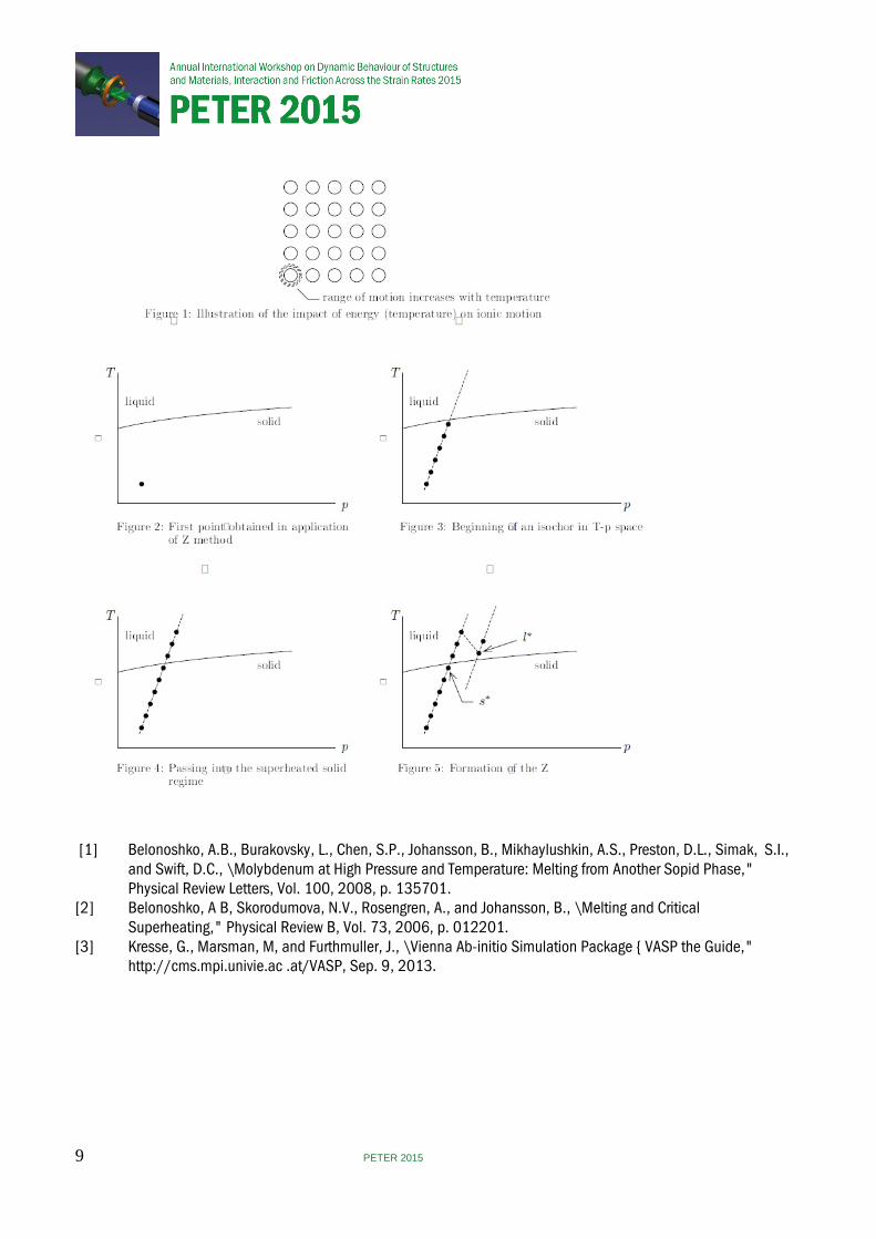
Using the Z method, we simulate the response of a computational cell constructed from an array of ions arranged in the desired crystalline configuration and possessing the desired impurity content. The analysis is conducted in NVE mode (number of ions, volume, and energy fixed) with reflective boundary conditions imposed upon the computational cell. A fundamental output from VASP is the history of motion of the ions that make up the computational cell. Numerous simulations are conducted with variations in E ranging from “low" to \high". As the energy (temperature) increases, the range of motion of the ions increases (Fig. 1). Melt occurs when disorder is achieved
Application of the Z method proceeds approximately as follows. First one conducts a simulation at a low enough value of energy that the material is sure to remain solid. The pressure and temperature are determined. This gives a point in T-p spa e (Fig. 2). Additional runs are conducted with the value of E being increased in each successive run. When these results are added to that of Fig. 2 we begin the mapping of an isochor (line of constant volume) in T-p spa e (Fig. 3). Additional runs are conducted with ever-increasing values of E. Eventually the isochor passes into the “liquid" regime while retaining the essence of its crystallographic structure. In this state it is a superheated solid (Fig. 4). Additional runs are conducted with ever-increasing values of E. Eventually the trace takes a “jog" into a fully liquid state. The isochor now takes on the shape of a “Z" from which the method derives its moniker (Fig. 5). Melt temperature Tm is now calculate in accordance with:
𝑘𝑘𝑚𝑚 = 12
(𝑘𝑘𝑙𝑙∗ + 𝑘𝑘𝑠𝑠∗) ± 12
(𝑘𝑘𝑙𝑙∗ − 𝑘𝑘𝑠𝑠∗)
Where l* is the lowest temperature point for which the analyst is confident that the material is liquid and s* is the highest temperature point for which the analyst is confident that the material is solid. The error bar in the Z method is typically < 5%. While the description of the Z method just given is somewhat simplistic, glossing over subtleties and potential complexities, it suffices for elucidating the general concepts and procedures that are embodied in the method. Further detail will be provided at PETER 2015.
8 PETER 2015
[1] Belonoshko, A.B., Burakovsky, L., Chen, S.P., Johansson, B., Mikhaylushkin, A.S., Preston, D.L., Simak, S.I., and Swift, D.C., \Molybdenum at High Pressure and Temperature: Melting from Another Sopid Phase," Physical Review Letters, Vol. 100, 2008, p. 135701. [2] Belonoshko, A B, Skorodumova, N.V., Rosengren, A., and Johansson, B., \Melting and Critical Superheating," Physical Review B, Vol. 73, 2006, p. 012201. [3] Kresse, G., Marsman, M, and Furthmuller, J., \Vienna Ab-initio Simulation Package { VASP the Guide," http://cms.mpi.univie.ac .at/VASP, Sep. 9, 2013.
9 PETER 2015
On the freezing of water under quasi-isentropic compression
S J P Stafford, D J Chapman, S N Bland and D E Eakins
Imperial College London, UK
Water has been previously observed to freeze into one of its many ice polymorphs, Ice VII1. This requires quasi-isentropic loading conditions above 3GPa, and is accompanied by a drop in optical transmission that corresponds to the nucleation and growth of the ice crystallites. The phase is entirely absent when sapphire surfaces compress water, as well as changes in transmission, making the water is metastable in the ice VII phase space. We present the results of experiments that explored this effect, as well as images at the limit of the metastability. Het-V data confirm that the water sees a phase change at approximately 6.5GPa but images of the water do not darken as expected. A transparent phase change is speculated.
[1] Dolan D H. et.al, Nature Physics, 3, 5, (2007)
Temperature and strain rate effects on the piezoelectric charge production of PZT 95/5
A S Khan and W G Proud
Imperial College London, UK
The effects of varying strain rates and temperatures on the charge output and fracture of the piezoceramic PZT 95/5 have been investigated. The samples are studied in the temperature range of -20°C to +80°C; a range of strain rates (10-4 s-1 to 10+3 s-1) is achieved using quasi-static loading equipment, drop weights and Split Hopkinson Pressure Bars. Stress-strain data is obtained, along with high-speed images, allowing the physical processes e.g. fracture, to be quantified.
The Institute of Shock Physics acknowledges the support of AWE, Aldermaston, UK and Imperial College London.
10 PETER 2015
Using Tensile plasticity and the dual domain material point method to model ductile failure for finite deformations
C C Long and D Z Zhang
Los Alamos National Laboratory, USA
Particle based computational methods have long been used to model high-energy and large deformation structural problems. In the present work, we incorporate a ductile damage material model into a computational frame-work based on the Dual Domain Material Point (DDMP) method. The essential elements of both the ductile damage model and DDMP are discussed. Simulations of the classical flyer-plate problem are carried out and compared to experiments performed at LANL [3]. The effects of overstress, artificial viscosity and physical viscosity are investigated.
The DDMP method is an improved version of the material point method (MPM) [4] and has been applied to many large deformation problems [2] with success. The problems calculated using the DDMP method include elastic deformation, plastic flow, and brittle failure. The present work intends to further extend the numerical use of the DDMP method to materials with ductile damage and strain softening.
Given the DDMP method's ability to accurately compute large deformation problems, we will also present a methodology for extending the Tensile Plasticity (TEPLA) [1] ductile damage model to finite deformations. The mathematical basis for this approach will be presented in detail, along with comparisons to the traditional implementation of TEPLA.
Similar to MPM, the DDMP method uses Lagrangian particles within an Eulerian grid [5]. These Lagrangian particles are free to move about the Eulerian mesh, and are used to store the material state. They can thus can be used with a history-dependent ductile material model, such as TEPLA. At each time step, data from the moving particles is transferred to the underlying grid where numerical analysis can be readily performed. Compared to the MPM, the newly developed Dual Domain Material Point (DDMP) method [5, 2] reduces cell crossing noise associated with traditional MPM approaches. This noise reduction is important in this flyer plate problem. In the region where the material is about to fail, the softening of the material leads to localized strain and large displacement of the particles causing them to move across cells.
The flyer-plate experiment is relatively straightforward: A plate is traveling at high velocity and strikes a stationary plate. These are referred to as the ‘flyer' plate and the ‘test' plate, respectively. The test plate has a thickness double that of the flyer plate. Upon impact, a compression shock travels through both plates to opposite surfaces. The reflected tensile expansion fans then collide at the center of the test plate, assuming uniform materials. For a critical value of initial velocity in the flyer plate, a typical ductile material softens and eventually fails alone the center line of the test plate. This problem is physically well defined, and presents numerous numerical challenges, including shock propagation, material softening and failure, and history dependent plasticity. Additional methods used to capture these effects, such as material overstress and artificial viscosity, are presented and discussed. All results are compared to experimental data carried out using a Tantalum flyer/test plate.
[1] J N Johnson and F L Adessio. Tensile plasticity and ductile failure. Journal of Applied Physics, 64:6699{6712, 1988. [2] X Ma, D Z Zhang, P T Giguere, and C Liu. Axisymmetric computation of Taylor cylinder impacts of ductile and brittle materials using original and dual domain material point methods. International Journal of Impact Engineering, 54:96{104, 2013. [3] J Millet, G Whiteman, N Bourne, S Case, and R Gray. Shear strength development in tantalum alloys: Effects of cold work and alloying. In Bulletin of the American Physical Society, volume 58, Seattle, Washing- ton, 2013. [4] D Sulsky, Z Chen, and H L Schreyer. A particle method for history dependent materials. Computational Methods in Applied Mechanics and Engineering, 118:179{196, 1994. [5] D Z Zhang, X Ma, and P T Giguere. Material point method enhanced by modified gradient of shape function. Journal of Computational Physics, 230:6379{6398, 2011.
11 PETER 2015
Compression behavior of new composite sandwich concrete block at quasi-static loading conditions
F Abed, A Aidan, and T Ibrahim
American University of Sharjah, United Arab Emirates
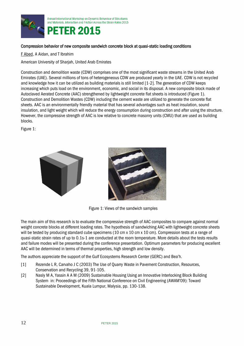
Construction and demolition waste (CDW) comprises one of the most significant waste streams in the United Arab Emirates (UAE). Several millions of tons of heterogeneous CDW are produced yearly in the UAE. CDW is not recycled and knowledge how it can be utilized as building materials is still limited [1-2]. The generation of CDW keeps increasing which puts load on the environment, economic, and social in its disposal. A new composite block made of Autoclaved Aerated Concrete (AAC) strengthened by lightweight concrete flat sheets is introduced (Figure 1). Construction and Demolition Wastes (CDW) including the cement waste are utilized to generate the concrete flat sheets. AAC is an environmentally friendly material that has several advantages such as heat insulation, sound insulation, and light weight which will reduce the energy consumption during construction and after using the structure. However, the compressive strength of AAC is low relative to concrete masonry units (CMU) that are used as building blocks.
Figure 1:
Figure 1: Views of the sandwich samples
The main aim of this research is to evaluate the compressive strength of AAC composites to compare against normal weight concrete blocks at different loading rates. The hypothesis of sandwiching AAC with lightweight concrete sheets will be tested by producing standard cube specimens (10 cm x 10 cm x 10 cm). Compression tests at a range of quasi-static strain rates of up to 0.1s-1 are conducted at the room temperature. More details about the tests results and failure modes will be presented during the conference presentation. Optimum parameters for producing excellent AAC will be determined in terms of thermal properties, high strength and low density.
The authors appreciate the support of the Gulf Ecosystems Research Center (GERC) and Bea’h.
[1] Rezende L R, Carvaho J C (2003) The Use of Quarry Waste in Pavement Construction, Resources, Conservation and Recycling 39, 91-105. [2] Nasly M A, Yassin A A M (2009) Sustainable Housing Using an Innovative Interlocking Block Building System in: Proceedings of the Fifth National Conference on Civil Engineering (AWAM’09): Toward Sustainable Development, Kuala Lumpur, Malysia, pp. 130-138.
12 PETER 2015
High resolution simulations of energy absorption in dynamically loaded cellular structures
R Winter and M Cotton
AWE, UK
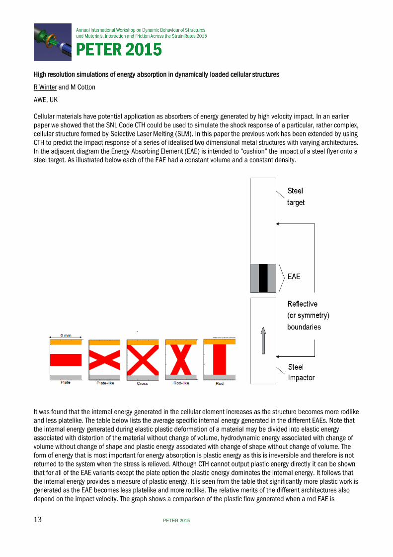
Cellular materials have potential application as absorbers of energy generated by high velocity impact. In an earlier paper we showed that the SNL Code CTH could be used to simulate the shock response of a particular, rather complex, cellular structure formed by Selective Laser Melting (SLM). In this paper the previous work has been extended by using CTH to predict the impact response of a series of idealised two dimensional metal structures with varying architectures. In the adjacent diagram the Energy Absorbing Element (EAE) is intended to “cushion” the impact of a steel flyer onto a steel target. As illustrated below each of the EAE had a constant volume and a constant density.
It was found that the internal energy generated in the cellular element increases as the structure becomes more rodlike and less platelike. The table below lists the average specific internal energy generated in the different EAEs. Note that the internal energy generated during elastic plastic deformation of a material may be divided into elastic energy associated with distortion of the material without change of volume, hydrodynamic energy associated with change of volume without change of shape and plastic energy associated with change of shape without change of volume. The form of energy that is most important for energy absorption is plastic energy as this is irreversible and therefore is not returned to the system when the stress is relieved. Although CTH cannot output plastic energy directly it can be shown that for all of the EAE variants except the plate option the plastic energy dominates the internal energy. It follows that the internal energy provides a measure of plastic energy. It is seen from the table that significantly more plastic work is generated as the EAE becomes less platelike and more rodlike. The relative merits of the different architectures also depend on the impact velocity. The graph shows a comparison of the plastic flow generated when a rod EAE is
13 PETER 2015
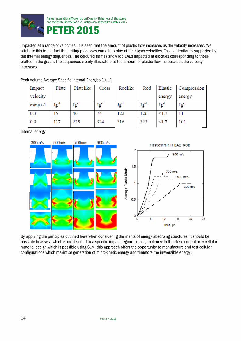
impacted at a range of velocities. It is seen that the amount of plastic flow increases as the velocity increases. We attribute this to the fact that jetting processes come into play at the higher velocities. This contention is supported by the internal energy sequences. The coloured frames show rod EAEs impacted at elocities corresponding to those plotted in the graph. The sequences clearly illustrate that the amount of plastic flow increases as the velocity increases.
Peak Volume Average Specific Internal Energies (Jg-1)
Internal energy
By applying the principles outlined here when considering the merits of energy absorbing structures, it should be possible to assess which is most suited to a specific impact regime. In conjunction with the close control over cellular material design which is possible using SLM, this approach offers the opportunity to manufacture and test cellular configurations which maximise generation of microkinetic energy and therefore the irreversible energy.
14 PETER 2015

Blast Propagation through Dampened Granular Media
H Badham, M Chalmers, T-T N Nguyen and W G Proud
Imperial College London, UK
Many previous studies have concentrated on the stress wave transmission and shock properties of sand in dry and wet conditions, data directly relevant to the sand used here are found in [1-5]. One result from these studies was that water did not significantly affect stress propagation in sand over the range from dry to 10% weight water. However, a marked change was found as water levels increased from 10 to 20%: the stress propagation was quicker and the shock rise time reduced. Qualitatively this change is to be expected as a material changes from a very porous solid-gas material to a liquid-solid mix, however, the precise quantitative changes are still subject to on-going investigation.
An initial study by the author [6] examined sand with respect to gas percolation to determine if the same processes and dependencies occurred with increasing water levels. This found that changes in blast propagation were found at low levels of water, 3% weight, with the propagation velocities being reduced by addition of water, the slowest propagation being found at 11% weight saturation, after which the propagation velocity increased as the system moved from a process of gas percolation to one of stress transmission.
The granular beds of differing thicknesses were studied in a shock tube by introducing by an additional section (see figure 1). One tube to contained the granular bed and a second tube, called the ‘extender’ tube. The length of the extender tube length was matched to the length of the granular bed to ensure that the overall distance between sensor 1 and sensor 2 was constant for all experiments. Bed lengths of 10, 15 and 20 cm were investigated in this study. In all cases the bed was prevented from moving by the presence of a thin section of reticulated foam and a perforated steel sheet at each end of the granular bed.
FIGURE 1: Schematic of the shock tube showing overview (top), detail of the section for the introduction of granular beds (lower left) and detail of the breech system (lower right).
The granular materials used were either mono-modal quartz sand (300-600 or 1180 – 2360 microns) or glass spheres (400-600 or1500 microns) to study the effect of particle morphology. In this study % volume is used in place of % weight, as the density of the glass is different to that of the sand, therefore, % volume provides a scale for direct comparison. The level of saturation studied was from dry to 1% volume water (corresponding to ~0.3% weight for the sand). At these levels the liquid was not forced from the granular bed by the driving pressure and the same sample could be subject to multiple loadings.
Figure 2 shows the variation in transit time of the pulse for the four granular materials with pressure, in all cases the granular beds were dry. It is interesting to note that at low pressures the materials divide according to particle size with the larger grain size sand and the larger glass spheres showing the faster transit times. As the blast pressure is increased the materials then group according to material type, probably as an effect of the sample morphology. The general decrease in transit time with increasing pressure is as expected as the velocity of a blast wave is pressure dependent.
15 PETER 2015
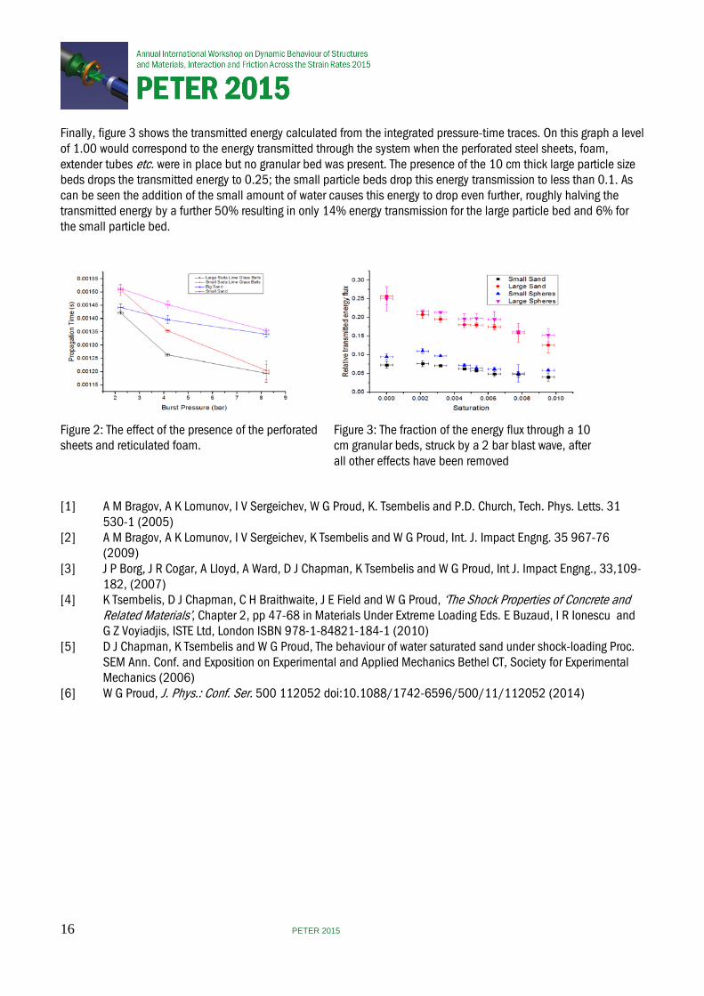
Finally, figure 3 shows the transmitted energy calculated from the integrated pressure-time traces. On this graph a level of 1.00 would correspond to the energy transmitted through the system when the perforated steel sheets, foam, extender tubes etc. were in place but no granular bed was present. The presence of the 10 cm thick large particle size beds drops the transmitted energy to 0.25; the small particle beds drop this energy transmission to less than 0.1. As can be seen the addition of the small amount of water causes this energy to drop even further, roughly halving the transmitted energy by a further 50% resulting in only 14% energy transmission for the large particle bed and 6% for the small particle bed.
Figure 2: The effect of the presence of the perforated sheets and reticulated foam.
Figure 3: The fraction of the energy flux through a 10 cm granular beds, struck by a 2 bar blast wave, after all other effects have been removed
[1] A M Bragov, A K Lomunov, I V Sergeichev, W G Proud, K. Tsembelis and P.D. Church, Tech. Phys. Letts. 31 530-1 (2005) [2] A M Bragov, A K Lomunov, I V Sergeichev, K Tsembelis and W G Proud, Int. J. Impact Engng. 35 967-76 (2009) [3] J P Borg, J R Cogar, A Lloyd, A Ward, D J Chapman, K Tsembelis and W G Proud, Int J. Impact Engng., 33,109- 182, (2007) [4] K Tsembelis, D J Chapman, C H Braithwaite, J E Field and W G Proud, ‘The Shock Properties of Concrete and Related Materials’, Chapter 2, pp 47-68 in Materials Under Extreme Loading Eds. E Buzaud, I R Ionescu and G Z Voyiadjis, ISTE Ltd, London ISBN 978-1-84821-184-1 (2010) [5] D J Chapman, K Tsembelis and W G Proud, The behaviour of water saturated sand under shock-loading Proc. SEM Ann. Conf. and Exposition on Experimental and Applied Mechanics Bethel CT, Society for Experimental Mechanics (2006) [6] W G Proud, J. Phys.: Conf. Ser. 500 112052 doi:10.1088/1742-6596/500/11/112052 (2014)
16 PETER 2015
The relevance of secondary frame in the structural response of spider orb webs upon prey impacts
A Soler and R Zaera
University Carlos III of Madrid, Spain
An orb-weaving spiders likelihood of survival is influenced by its ability to withstand prey impact with minimum damage to its web and at the lowest manufacturing cost. This set of requirements has forced the spider silk to evolve towards extreme strength and ductility to a degree that is rare among natural or artificial materials. However, the superior performance of the orb-web as a prey aerial trap is not due merely to the exceptional strength and ductility of the silk but also to a consummate structural topology. Both factors are intimately related, the arrangement of the threads making the most efficient use of the different silks spun by the spider. Indeed, the orb-web is typically composed of a spiral made of sticky and tough threads which can deform without breaking, supported by a scaffold made of strong and rather stiff major ampullate threads (mooring, frame and radii) keeping the sticky silk in place and transmitting the impact load to the substrate (Zschokke[1]) (Fig. 1).
The strength of the web is strongly dependent on a suited distribution of the silk mass, a scarce and valuable resource for the spider, among the different thread types, and on an appropriate positioning of these threads. Recalling the Maxwells lemma, the optimal shape of a structure in terms of least mass is that for which all members are equally stressed near the breaking load. Despite the fact that no spiderweb topology can fulfill this condition, the lemma highlights the benefit of a structural shape resulting in an even distribution of stresses upon the prey impact. Uncovering the strategies which contribute to a uniform stress state in a structure of superior performance such as the web, not only helps to understand how evolutionary driving forces shaped it but also provides design principles that might apply to other structural systems.
In spite of much research into the mechanical behavior of the orb-web, the relevance of the secondary frame in its structural behavior often went unnoticed. This part of the scaffold demands a negligible mass of the silk as compared to spiral, radial and even to primary frame, but its contribution to an even distribution of stresses among the threads is of central importance according to the findings herein presented. Here we report web impact simulations that permit to identify the mechanisms behind their efficiency, highlight their differential effect in the different silk sub-structures, quantify their benefits in terms of stress uniformity, and gives the basis for assessing its optimal length.
Modelling wind load and prey impact on orb webs involves the three characteristic sources of non-linearities in solid mechanics: large deformations, contacts and non-linear behaviour of materials. The short duration of the event and the presence of these non-linearities make the use of an explicit finite element code to solve the equilibrium equations recommendable. The explicit solver of the finite element code ABAQUS/Explicit 6.14-1 has been used for this purpose. The orb web geometry (Fig.1 (a)) is defined by eleven parameters. In order to perform parametric analysis, a script was developed to generate the finite-element model. Threads were modelled considering two different silks: the viscid silk for spiral threads and the major ampullate silk for mooring, radii and frame threads. The hysteretic cycle was defined by a microstructured-based continuum model described in [2]. The prey was modelled as a rigid spherical surface of 20mm diameter and weighing 0.03 g. A boundary condition of velocity V = 2 m/s at normal incidence to the web plane was assumed for the prey. A user element subroutine VUEL of a two-node truss element was implemented to account for both hysteretic behaviour
17 PETER 2015
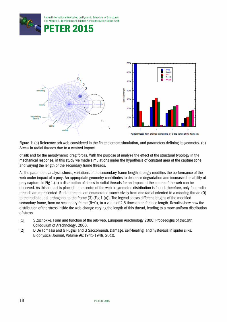
Figure 1: (a) Reference orb web considered in the finite element simulation, and parameters defining its geometry. (b) Stress in radial threads due to a centred impact.
of silk and for the aerodynamic drag forces. With the purpose of analyse the effect of the structural typology in the mechanical response, in this study we made simulations under the hypothesis of constant area of the capture zone and varying the length of the secondary frame threads.
As the parametric analysis shows, variations of the secondary frame length strongly modifies the performance of the web under impact of a prey. An appropriate geometry contributes to decrease degradation and increases the ability of prey capture. In Fig 1.(b) a distribution of stress in radial threads for an impact at the centre of the web can be observed. As this impact is placed in the centre of the web a symmetric distribution is found, therefore, only four radial threads are represented. Radial threads are enumerated successively from one radial oriented to a mooring thread (0) to the radial quasi-orthogonal to the frame (3) (Fig 1.(a)). The legend shows different lengths of the modified secondary frame, from no secondary frame (R=0), to a value of 2.5 times the reference length. Results show how the distribution of the stress inside the web change varying the length of this thread, leading to a more uniform distribution of stress.
[1] S Zschokke, Form and function of the orb-web, European Arachnology 2000: Proceedigns of the19th Colloquium of Arachnology, 2000. [2] D De Tomassi and G Puglisi and G Saccomandi, Damage, self-healing, and hysteresis in spider silks, Biophysical Journal, Volume 96:1941-1948, 2010.
18 PETER 2015
Numerical simulation of dynamic processes in metal foams. I. virtual metallic foam
R B Pęcherski, M Nowak and Z Nowak
Polish Academy of Sciences, Poland
The design of new multifunctional foams requires the solution of the following questions: in what way to fabricate metallic foams of assumed skeleton structure, how to produce tomograms, i.e. 3D virtual foam reconstructions of real foam structure [1], how to elaborate methods of numerical simulations of assumed processes in auxetic foams with use of the tomograms.
Depending on manufacturing method the cells obtain convex or concave shape. The materials with convex cell structure reveal positive value of Poisson’s ratio, that is if a sample is stretching, then its cross-section is getting thinner. The complex structure of the foam related with reentrant cells produces the opposite effect during stretching of a sample, i.e. its cross-section is increasing. Then the negative Poisson’s ratio is observed and such foams become auxetic.
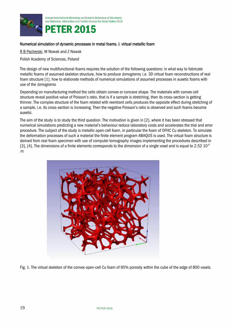
The aim of the study is to study the third question. The motivation is given in [2], where it has been stressed that numerical simulations predicting a new material’s behaviour reduce laboratory costs and accelerates the trial and error procedure. The subject of the study is metallic open-cell foam, in particular the foam of OFHC Cu skeleton. To simulate the deformation processes of such a material the finite element program ABAQUS is used. The virtual foam structure is derived from real foam specimen with use of computer tomography images implementing the procedures described in [3], [4]. The dimensions of a finite elements corresponds to the dimension of a single voxel and is equal to 2.52 10-6 m.
Fig. 1. The virtual skeleton of the convex open-cell Cu foam of 95% porosity within the cube of the edge of 800 voxels.
19 PETER 2015
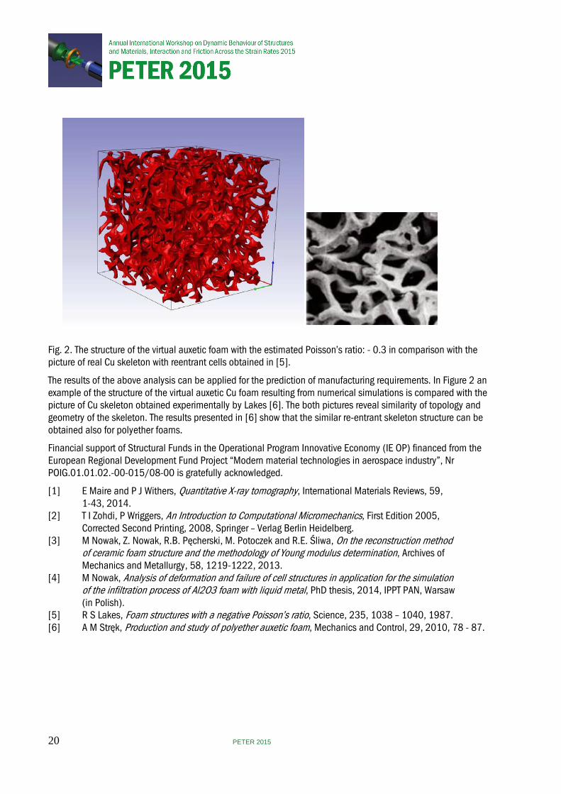
Fig. 2. The structure of the virtual auxetic foam with the estimated Poisson’s ratio: - 0.3 in comparison with the picture of real Cu skeleton with reentrant cells obtained in [5].
The results of the above analysis can be applied for the prediction of manufacturing requirements. In Figure 2 an example of the structure of the virtual auxetic Cu foam resulting from numerical simulations is compared with the picture of Cu skeleton obtained experimentally by Lakes [6]. The both pictures reveal similarity of topology and geometry of the skeleton. The results presented in [6] show that the similar re-entrant skeleton structure can be obtained also for polyether foams.
Financial support of Structural Funds in the Operational Program Innovative Economy (IE OP) financed from the European Regional Development Fund Project “Modern material technologies in aerospace industry”, Nr POIG.01.01.02.-00-015/08-00 is gratefully acknowledged.
[1] E Maire and P J Withers, Quantitative X-ray tomography, International Materials Reviews, 59, 1-43, 2014. [2] T I Zohdi, P Wriggers, An Introduction to Computational Micromechanics, First Edition 2005, Corrected Second Printing, 2008, Springer – Verlag Berlin Heidelberg. [3] M Nowak, Z. Nowak, R.B. Pęcherski, M. Potoczek and R.E. Śliwa, On the reconstruction method of ceramic foam structure and the methodology of Young modulus determination, Archives of Mechanics and Metallurgy, 58, 1219-1222, 2013. [4] M Nowak, Analysis of deformation and failure of cell structures in application for the simulation of the infiltration process of Al2O3 foam with liquid metal, PhD thesis, 2014, IPPT PAN, Warsaw (in Polish). [5] R S Lakes, Foam structures with a negative Poisson’s ratio, Science, 235, 1038 – 1040, 1987. [6] A M Stręk, Production and study of polyether auxetic foam, Mechanics and Control, 29, 2010, 78 - 87.
20 PETER 2015
Numerical simulation of the dynamic processes in metal foams. Part II. Compression tests of open cell copper foams
Z Nowak, M Nowak and R B Pęcherski
Polish Academy of Sciences, Poland
Metallic cellular materials have been widely acknowledged for their multifunctional applications related also with energy absorption capability in addition to their light weight. In recent years, the auxetic materials revealing negative Poisson’s ratio have attracted much attention. Up to date, the research of auxetics is mainly concentrating on the cell design [1], [2] and the static response [3], although the auxetic materials also demonstrate potential for energy absorption, fracture retardant, and high-velocity impacts resistance. In the paper, a comparative study is reported on the high-velocity impact responses of two type metallic cellular foams, that is, convex open cell foam [4] and auxetic foam. The impact limits and absorption energy of the two foams are obtained by means of explicit nonlinear finite element simulations using ABAQUS [5]. It has been found that the auxetic foam is superior to the convex cell foam in impact resistance because of the material concentration at the impacted area due to the negative Poisson’s ratio effect.
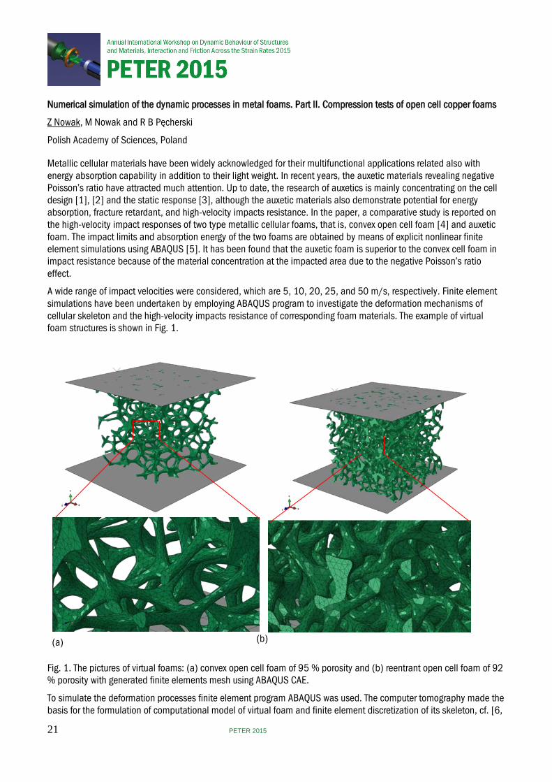
A wide range of impact velocities were considered, which are 5, 10, 20, 25, and 50 m/s, respectively. Finite element simulations have been undertaken by employing ABAQUS program to investigate the deformation mechanisms of cellular skeleton and the high-velocity impacts resistance of corresponding foam materials. The example of virtual foam structures is shown in Fig. 1.
(a) (b)
Fig. 1. The pictures of virtual foams: (a) convex open cell foam of 95 % porosity and (b) reentrant open cell foam of 92 % porosity with generated finite elements mesh using ABAQUS CAE.
To simulate the deformation processes finite element program ABAQUS was used. The computer tomography made the basis for the formulation of computational model of virtual foam and finite element discretization of its skeleton, cf. [6,
21 PETER 2015
7]. The dimension of the finite element corresponds to the dimension of a single voxel equal to 16m. In all numerical calculations the cube-shaped sample of the foam with dimensions of 800x800x800 voxels is considered. Such assumption leads to the representative volume element of the size 2x2x2 mm. The material of the skeleton of the virtual foam is assumed to be isotropic and elastic-plastic. For numerical simulations the constitutive relation is applied which defines the behaviour of oxygen-free high conductivity copper (OFHC) using the experimental data reported in Nemat-Nasser and Li [8] and Rusinek at al. [9]. Finite element calculations are made with use of four node C3D4 tetrahedral elements. The finite elements model consists of 204575 nodes and 670073 elements for the auxetic foam, and 129720 nodes and 506747 elements for convex cell foam. Fig. 1a and 1b represent the virtual foam samples with 92% and 95% porosity. In numerical simulations the bottom surface of the sample is fully constrained and the top surface of this sample is moved parallel to the vertical axis. The resulting force is calculated for each time increment. The comparison of numerical predictions of axial force within the range of velocity (5-50 m/s) are made.
In this work, the impact resistance of auxetic foam is analysed using ABAQUS finite element program. For comparison, the traditional convex open cell copper foam samples of identical dimensions is also included in the numerical study. Using the numerical models, a parametric study has been carried out to examine the effect of impact velocity on the absorbed energy of both types of foams. The main findings from the study can be outlined as follows. (1) The auxetic foam yields lower final axial displacement for the same compression time and velocity of the impact than the metallic foams with conventional convex cells. The advantage of auxetic foam becomes larger as the impact velocity decreases. (2) Energy absorption of auxetic foam decreases with increased impact velocity within the investigated range. Financial support of Structural Funds in the Operational Program Innovative Economy (IE OP) financed from the European Regional Development Fund Project "Modern material technologies in aerospace industry", Nr POIG.01.01.02-00-015/08-00 is gratefully acknowledged.
[1] J N Grima, R Gatt, N Ravirala, A Alderson and K E Evans, Negative Poisson’s ratios in cellular foam materials, Materials Science and Engineering A, 423 (1-2), 214–218, 2006.
[2] E Pasternak and A V Dyskin, Materials and structures with macroscopic negative Poisson’s ratio, International Journal of Engineering Science, 52, 103–114, 2012. [3] J Dirrenberger, S Forest, D Jeulin, Elastoplasticity of auxetic materials, Computational Materials Science, 64, 57–61, 2012. [4] L J Gibson and M F Ashby. Cellular Solids, Structure and Properties, 2nd edition, Cambridge, 1999. [5] Simulia, ABAQUS/Explicit User’s Manual, ver. 6.13, Dassault Systémes, Providence, USA, 2013. [6] M Nowak, Z Nowak, R B Pęcherski, M Potoczek and R E Śliwa. On the reconstruction method of ceramic foam structures and the methodology of Young modulus determination, Archives of Metallurgy and Materials, Vol. 58, 1219-1222, 2013. [7] M Kirca, A Gul, E Ekinci, F Yadim and A Mugan. Computational modeling of micro-cellular carbon foams, Finite Elements in Analysis and Design, 44, 45-52, 2007. [8] S Nemat-Nasser, Y Li, Flow stress of FCC polycrystals with application to OFHC copper, Acta Mater., 46, 565– 577, 1998. [9] A Rusinek, J A Rodriguez-Martinez, A Arias, A thermo-viscoplastic constitutive model for FCC metals with application to OFHC copper, International Journal of Mechanical Sciences, 52, 120–135, 2010.
22 PETER 2015
(Invited) Dynamic experiments of materials on high-pulsed power generator CQ-4
G Wang, B Luo, T Chong, L Cao, J Zhao, C Sun, F Tan, C Liu, J Cai, X Chen, G Wu, X Zhang and H Zhang
China Academy of Engineering Physics, China
Over last two decades, high pulsed power generators had been widely applied in researches of high energy density physics, material science, astrophysics and so on. For example, the wire array and liner implosion dynamics, inertial confinement fusion physics and material dynamics are researched based on large-scale high pulsed power generators Z[1] ,Atlas[2] and PTS[3]. In recent ten years, the techniques of magnetically driven quasi-isentropic compression and high velocity flyer plates were developed and used to research the dynamics of materials at extreme conditions based on large-scale and compact high pulsed power generators[4-6]. A compact high pulsed power generator CQ-4 was developed and applied in investigating material dynamics at Institute of Fluid, China Academy of Engineering Physics in 2011, which can produce 1-100GPa ramp wave pressures with rising time of 400-600ns in material samples and accelerate aluminum flyer plates to more than 10 km/s for shock wave loadings[7] . Many applications have being done on CQ-4, such as isentropes and equations of states(EOS) of materials, dynamic strength and constitutive relationships of materials, phase transition dynamics and microstructure evolution of materials under ramp and shock wave loadings[8-12]. Two kinds of typical applications are introduced in this paper. One is the isentrope and EOS verification of pure Tantalum under ramp wave loadings, of which the effect of strength on the isentrope of material can’t be neglected. The other is the phase transition dynamics of polycrystal iron under ramp wave loadings and the microstructure evolution of recovered iron samples under shock wave loadings on CQ-4.
Shock Hugoniot data have been widely used to calibrate analytic equations of state (EOSs) of condensed matter at high pressures. However, the suitability of particular analytic EOSs under off-Hugoniot states has not been sufficiently verified using experimental data. We have conducted quasi-isentropic compression experiments (ICEs) of tantalum using the compact pulsed power generator CQ-4, and explored the relation of longitudinal stress versus volume of tantalum under quasi-isentropic compression using backward integration and characteristic inverse methods. By subtracting the deviatoric stress and additional pressure caused by irreversible plastic dissipation, the isentropic pressure can be extracted from the longitudinal stress. Several theoretical isentropes are deduced from analytic EOSs and compared with ICE results to validate the suitability of these analytic EOSs in isentropic compression states. The comparisons show that the Gruneisen EOS with Gruneisen Gamma proportional to volume is accurate, regardless whether the Hugoniot or isentrope is used as the reference line. The Vinet EOS yields better accuracy in isentropic compression states. Theoretical isentropes derived from Tillotson, PUFF, and Birch-Murnaghan EOSs well agree with the experimental isentrope in the range of 0–100 GPa, but deviate gradually with pressure increasing further.
Iron, a typical polymorphic phase transition at 13GPa, has being researched in experiments and simulations for tens of years. The phase transition dynamics of polycrystal iron under ramp and shock wave loadings are also researched by us in experiments and simulations with multi-phase equation of state. The relaxation time, initial pressure, stress wave evolution and microstructure evolution of recovered samples are obtained and analyzed, which show that the phase transition relaxation time is about 30ns, and that the phase transition pressure is about 13 GPa, and that the numerical and experimental interface velocities are essentially coincident, and that the sound speed drop and the acoustic impedance of the window are the main factors to affect the interface velocity waveform in the conditions of ramp wave loadings.
For shock loading experiments, 7-40 GPa pressures are obtained to shock pure iron and the samples are recovered for metallographic analysis. The Electronic Backscatter Diffraction(EBSD) is used to observe the microstructure evolution of recovered iron samples at different shock pressures, which are compared with the results of Classical macro-continuum mechanics and phase-field simulations. The results show that a non-phase transition zone exists near the free surface of sample, the thickness of which depends on the loading pressure. The smaller the thickness is, the higher the loading pressure is, which is very similar to the phenomenon of near free surface of metal under detonation loading for shock melting.
23 PETER 2015

These work was supported by National Natural Science Foundation of China under Contract No.11327803,11176002, 11272295, 10927201, 11002130, and the Science Foundation of CAEP under contract Nos. 2011A0101001 and 2010A0201006.
[1] M E Cuneo et al, IEEE TRANSACTIONS ON PLASMA SCIENCE, VOL. 40, NO. 12, 2012 [2] S C Hsu, LA-UR-13-25430,2013 [3] J Deng et al, IEEE TRANSACTIONS ON PLASMA SCIENCE, VOL. 41, NO. 10, 2013 [4] J L Brown et al, Journal of Applied Physics 115, 043530 (2014) [5] T Ao and J R Asay, Rev. Sci. Instrum. 79 013903(2008) [6] A Lefrançois et al, IEEE TRANSACTIONS ON PLASMA SCIENCE, VOL. 39, NO. 1, JANUARY 2011 [7] G Wang et.al, Rev.Sci.Instrum.84, 015117, 2013. [8] Luo B, Wang G, Mo J et al, J. Appl. Phys., 2014,116(19):193506 [9] C Tao, Wang Guiji, Tan F et al., SCIENTIA SINICA Physica, Mechanica & Astronomica, 2014,44(6), 630- 636
(in Chinese) [10] Luo B, Wang G, Tan F, et al., Chinese Journal of Theoretical and Applied Mechanics,2014, 46(2), 241-247 (in Chinese) [11] G Wang , J Cai et al, Eur. Phys. J. Appl. Phys. (2012) 60: 21001 [12] L Cao, Master thesis,China Academy of Engineering Physics, 2014
24 PETER 2015
Exploding wire technology for control of structure subjected to low velocity impact
M Ostrowski1,2 and P Pawłowski 2
1Invenco R&D Company, Poland, 2 Polish Academy of Sciences, Poland
Control of crash or impact process may be based on change of mechanical characteristics due to modification of inner structural connections. Presented work covers numerical and experimental analysis of sandwich fabric composite cantilever beam subjected to a low velocity impact. A set of metallic electrical conductors was placed between composite layers causing their controlled delamination when subjected to an electrical explosion. In result, separation of initially connected components in the vicinity of the exploded conductor is obtained, leading to the change of global mechanical characteristics, allowing for modification of beam behavior.
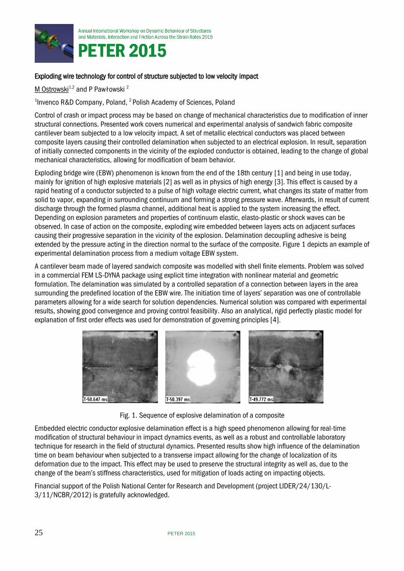
Exploding bridge wire (EBW) phenomenon is known from the end of the 18th century [1] and being in use today, mainly for ignition of high explosive materials [2] as well as in physics of high energy [3]. This effect is caused by a rapid heating of a conductor subjected to a pulse of high voltage electric current, what changes its state of matter from solid to vapor, expanding in surrounding continuum and forming a strong pressure wave. Afterwards, in result of current discharge through the formed plasma channel, additional heat is applied to the system increasing the effect. Depending on explosion parameters and properties of continuum elastic, elasto-plastic or shock waves can be observed. In case of action on the composite, exploding wire embedded between layers acts on adjacent surfaces causing their progressive separation in the vicinity of the explosion. Delamination decoupling adhesive is being extended by the pressure acting in the direction normal to the surface of the composite. Figure 1 depicts an example of experimental delamination process from a medium voltage EBW system.
A cantilever beam made of layered sandwich composite was modelled with shell finite elements. Problem was solved in a commercial FEM LS-DYNA package using explicit time integration with nonlinear material and geometric formulation. The delamination was simulated by a controlled separation of a connection between layers in the area surrounding the predefined location of the EBW wire. The initiation time of layers’ separation was one of controllable parameters allowing for a wide search for solution dependencies. Numerical solution was compared with experimental results, showing good convergence and proving control feasibility. Also an analytical, rigid perfectly plastic model for explanation of first order effects was used for demonstration of governing principles [4].
Fig. 1. Sequence of explosive delamination of a composite
Embedded electric conductor explosive delamination effect is a high speed phenomenon allowing for real-time modification of structural behaviour in impact dynamics events, as well as a robust and controllable laboratory technique for research in the field of structural dynamics. Presented results show high influence of the delamination time on beam behaviour when subjected to a transverse impact allowing for the change of localization of its deformation due to the impact. This effect may be used to preserve the structural integrity as well as, due to the change of the beam’s stiffness characteristics, used for mitigation of loads acting on impacting objects.
Financial support of the Polish National Center for Research and Development (project LIDER/24/130/L-3/11/NCBR/2012) is gratefully acknowledged.
25 PETER 2015

[1] Turner B, A study of exploding wires, PhD Thessis , California Institute of Technology, Pasadena, 1960, pp. 1-3. [2] Hrousis C A, Christensen J S, Advances in modeling exploding bridgewire initiation, 14th International Detonation Symposium, Coeur d'Alene, 2010. [3] Garasi C J et al., Multi-dimensional high energy density physics modelling and simulation of wire array Z- pich physics, Phisics of Plasma, AIP, 2004, vol. 11/5. [4] W J Stronge, T X Yu, Dynamic models for structural plasticity, Springer, 1993.
26 PETER 2015
Mesoscale simulations of the compaction of granular Tungsten Carbide: Benchmarking iSALE against CTH
J G Derrick, G S Collins and T M Davison
Imperial College London, UK
Understanding shock propagation in granular materials is important for a wide range of fields, from civil defense to planetary science. Granular materials in bulk are often modelled as a continuum due to resolution or computational constraints, with the effects of porosity implemented as extra material properties. To improve these models, numerical modelling is performed at the ‘meso scale’, a mid-level scale, where large numbers of individual grains are resolved. The simulations can illuminate grain level processes and examine the bulk response of the particles. Here we perform meso scale simulations using the shock physics code iSALE [1]. We compare results with those of CTH and experimental data [2, 3].
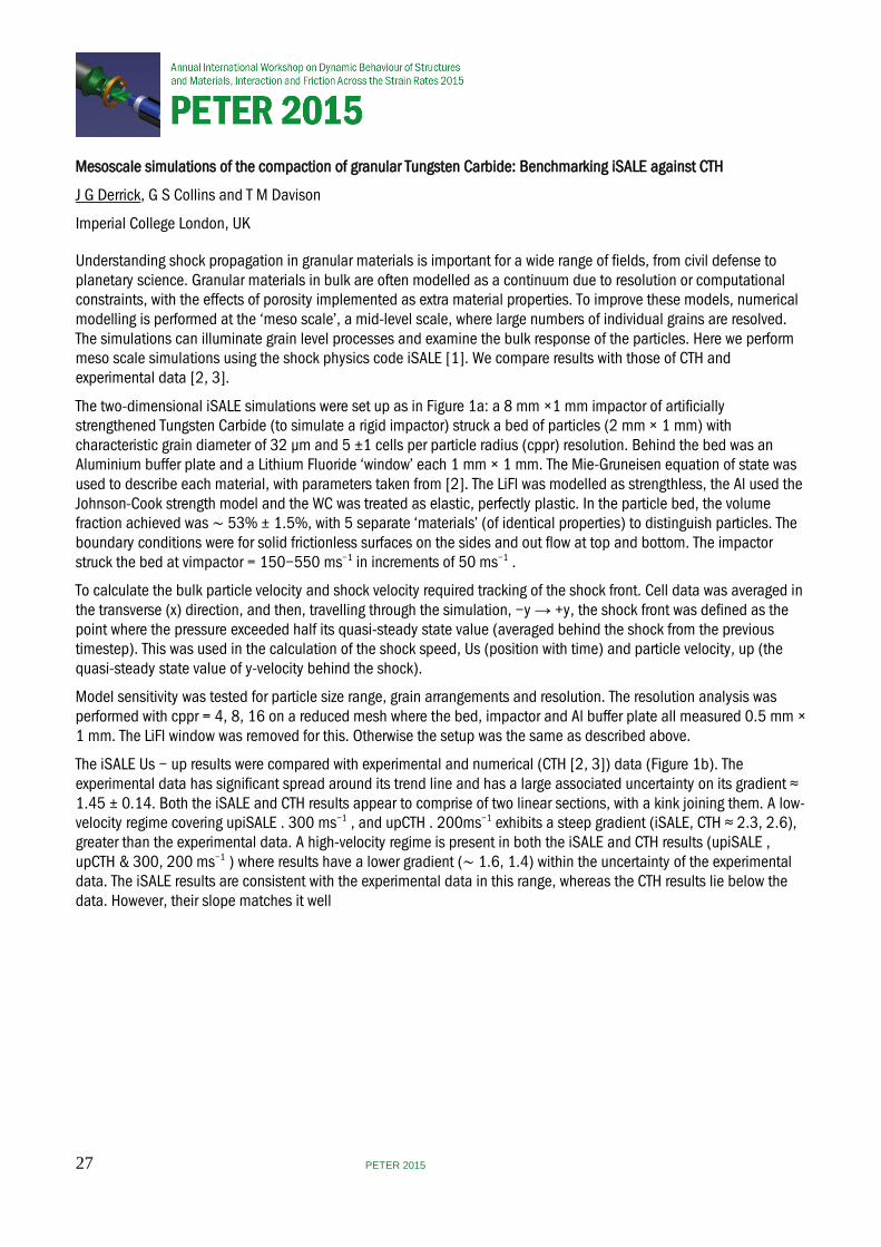
The two-dimensional iSALE simulations were set up as in Figure 1a: a 8 mm ×1 mm impactor of artificially strengthened Tungsten Carbide (to simulate a rigid impactor) struck a bed of particles (2 mm × 1 mm) with characteristic grain diameter of 32 µm and 5 ±1 cells per particle radius (cppr) resolution. Behind the bed was an Aluminium buffer plate and a Lithium Fluoride ‘window’ each 1 mm × 1 mm. The Mie-Gruneisen equation of state was used to describe each material, with parameters taken from [2]. The LiFl was modelled as strengthless, the Al used the Johnson-Cook strength model and the WC was treated as elastic, perfectly plastic. In the particle bed, the volume fraction achieved was ∼ 53% ± 1.5%, with 5 separate ‘materials’ (of identical properties) to distinguish particles. The boundary conditions were for solid frictionless surfaces on the sides and out flow at top and bottom. The impactor struck the bed at vimpactor = 150−550 ms−1 in increments of 50 ms−1 .
To calculate the bulk particle velocity and shock velocity required tracking of the shock front. Cell data was averaged in the transverse (x) direction, and then, travelling through the simulation, −y → +y, the shock front was defined as the point where the pressure exceeded half its quasi-steady state value (averaged behind the shock from the previous timestep). This was used in the calculation of the shock speed, Us (position with time) and particle velocity, up (the quasi-steady state value of y-velocity behind the shock).
Model sensitivity was tested for particle size range, grain arrangements and resolution. The resolution analysis was performed with cppr = 4, 8, 16 on a reduced mesh where the bed, impactor and Al buffer plate all measured 0.5 mm × 1 mm. The LiFl window was removed for this. Otherwise the setup was the same as described above.
The iSALE Us − up results were compared with experimental and numerical (CTH [2, 3]) data (Figure 1b). The experimental data has significant spread around its trend line and has a large associated uncertainty on its gradient ≈ 1.45 ± 0.14. Both the iSALE and CTH results appear to comprise of two linear sections, with a kink joining them. A low-velocity regime covering upiSALE . 300 ms−1 , and upCTH . 200ms−1 exhibits a steep gradient (iSALE, CTH ≈ 2.3, 2.6), greater than the experimental data. A high-velocity regime is present in both the iSALE and CTH results (upiSALE , upCTH & 300, 200 ms−1 ) where results have a lower gradient (∼ 1.6, 1.4) within the uncertainty of the experimental data. The iSALE results are consistent with the experimental data in this range, whereas the CTH results lie below the data. However, their slope matches it well
27 PETER 2015
suggesting a systematic difference separates them, which is most likely related to grain strength [3]. The most significant difference between the results is the location of the kink, which occurs at much lower up for CTH. The experimental data, however, does not appear to exhibit this kink.
Further comparison was achieved by transforming the values in 1b into stress-density space, using the Rankine-Hugoniot conservation of momentum equation (Figure 1c). This eliminates the effect of slightly different porosities by removing the influence of initial density. In this space iSALE’s high-velocity data are more consistent with the experimental data than the CTH results, and some of low-velocity regime results also appear to be consistent with the experimental data, unlike in 1b. CTH lies below both datasets, and only intersects the experimental data for lower densities. The CTH low-velocity regime has no equivalent experimental data to be compared to in either figure as its low velocity regime occurs outside of the experimental data range. The sensitivity analysis found no significant change in result when varying the particle size range over small scales, or for different grain arrangements in the bed. Resolution test results suggest increasing values of shock velocity by ≈ 1.6% from an increase of 4 to 8cppr and ≈ 0.6% from 8 to 16 cppr, indicating this has a small effect on the simulations.
At high particle velocities, iSALE is in good agreement with the experimental data, but at low velocities iSALE underestimates shock speed, suggesting too much dissipation occurs in these simulations. CTH also manifests a kink in its results for low velocities, however these do not overlap with the experimental data which does not manifest a kink at all. At higher velocities, the CTH results have a slope that is more consistent with experimental data but lie below it. The discrepancy between iSALE and CTH may be due to a number of differences in model set-up. For example the CTH models use a rigid drive plate impactor, as well as periodic boundary conditions and a different grain arrangement. The kink visible in both sets of numerical results might be related to the transition from compaction to grain rearrangement. This is likely to be sensitive to how grain strength and grain interfaces are dealt with in CTH and iSALE.
[1] K W¨unnemann, G Collins, and H Melosh, “A strain-based porosity model for use in hydrocode simulations of impacts and implications for transient crater growth in porous targets,” Icarus, vol. 180, no. 2, pp. 514 – 527, 2006. [2] J P Borg and T J Vogler, “Mesoscale calculations of the dynamic behavior of a granular ceramic,” International Journal of Solids and Structures, vol. 45, no. 6, pp. 1676 – 1696, 2008. [3] J P Borg and T J Vogler, “Mesoscale calculations of shock loaded granular ceramics,” AIP Conference Proceedings, vol. 955, no. 1, 2007.
28 PETER 2015
Resolving the dynamic response of sand
J W LaJeunesse1, M G Schumaker1, S T Stewart2 and D J P Borg1
1Marquette University, USA, 2University of California, USA
The dynamic response of bulk sand can be modeled by resolving each individual sand grain. These simulations are called mesoscale calculations because they resolve length scales in between bulk (i.e. the macroscale) and the grain (i.e. the microscale). In so doing the macroscopic response is determined while simultaneously providing insight into the grain level response during the shock loading event. The mesoscale simulations can provide insight into how phenomenological mechanisms at the microscale manifest themself at the macroscale.The current work aims to recreate four experimental impact experiments on dry sand using a massively parallel hydrocode, CTH, which is developed at Sandia National Laboratories.
Experiments were performed on a two-stage gas gun with a 50.8 mm bore launch tube. A copper flyer (~ 6.3 mm thick), copper driver (~ 1.5 mm thick), sand capsule (~ 5.0 mm thick), and PMMA window (~ 13.0 mm thick) was used for each experiment. Two experiments used large diameter Oklahoma sand grains (425 – 500 µm) and another two used small diameter Oklahoma sand grains (75 – 150 µm). The sand in each experiment was packed to a final density of about 1.73 g/cm3. A shot velocity of 1440 m/s and 1000 m/s were used for both the large and small diameter grains. Particle velocity data from a VISAR was collected from the backside of the sand capsule.
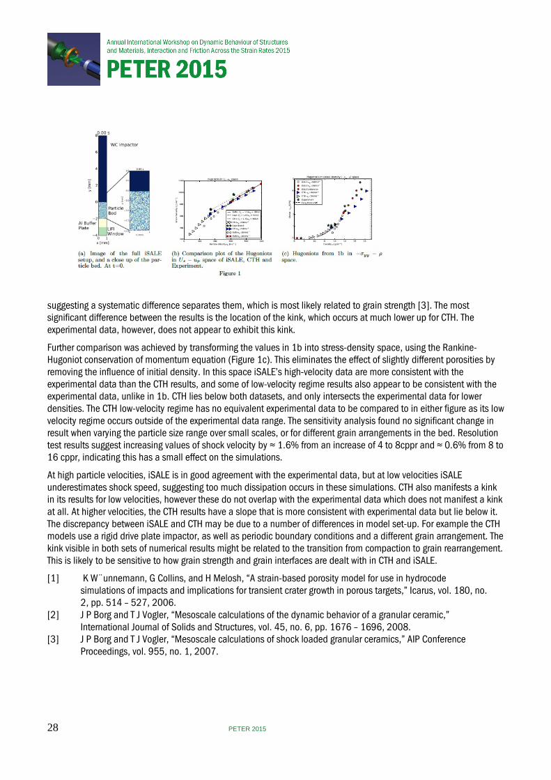
The sand realizations of randomly packed spherical quartz grains were generated using a discrete element method code, LIGGGHTS, which is also developed at Sandia National Laboratories, and imported into CTH. The grains were packed into a 5.0 mm x 5.0 mm x 5.0 mm computational domain and yielded an initial sand density of 1.73 g/cm3. Two different grain diameters of 483 µm and 133 µm were selected to mimic the large and small grain sizes used in the experiments. A resolution of 10 cells across the diameter of each grain was used. Mie-Grüneisen equations of state and Von Mises, elastic-perfectly plastic strength models were used for each material and their individual parameters were either taken from [1,2] or from the CTH library. Outflow conditions were selected for the inlet and outlet in the longitudinal direction and periodic conditions for each sidewall in the lateral direction.
The experimentally obtained particle velocity profiles (VISAR) were recreated in CTH by placing 100 tracer points across the sand-PMMA interface, the pressure response of the target was inferred from the particle velocity. The heterogeneous nature of the sand realizations disrupt planar shock propagation during dynamic loading, which can be observed using these multiple tracers. Since the VISAR laser spot collects data across the size of roughly one sand grain, the observed particle velocity profile is highly dependent on the local grain realization near the sand-PMMA interface. Using multiple tracers across the interface allows for velocity profiles to be measured near multiple local grain realizations and ultimately helps display the dispersion of the shock front as a result of different size sand grains.
29 PETER 2015
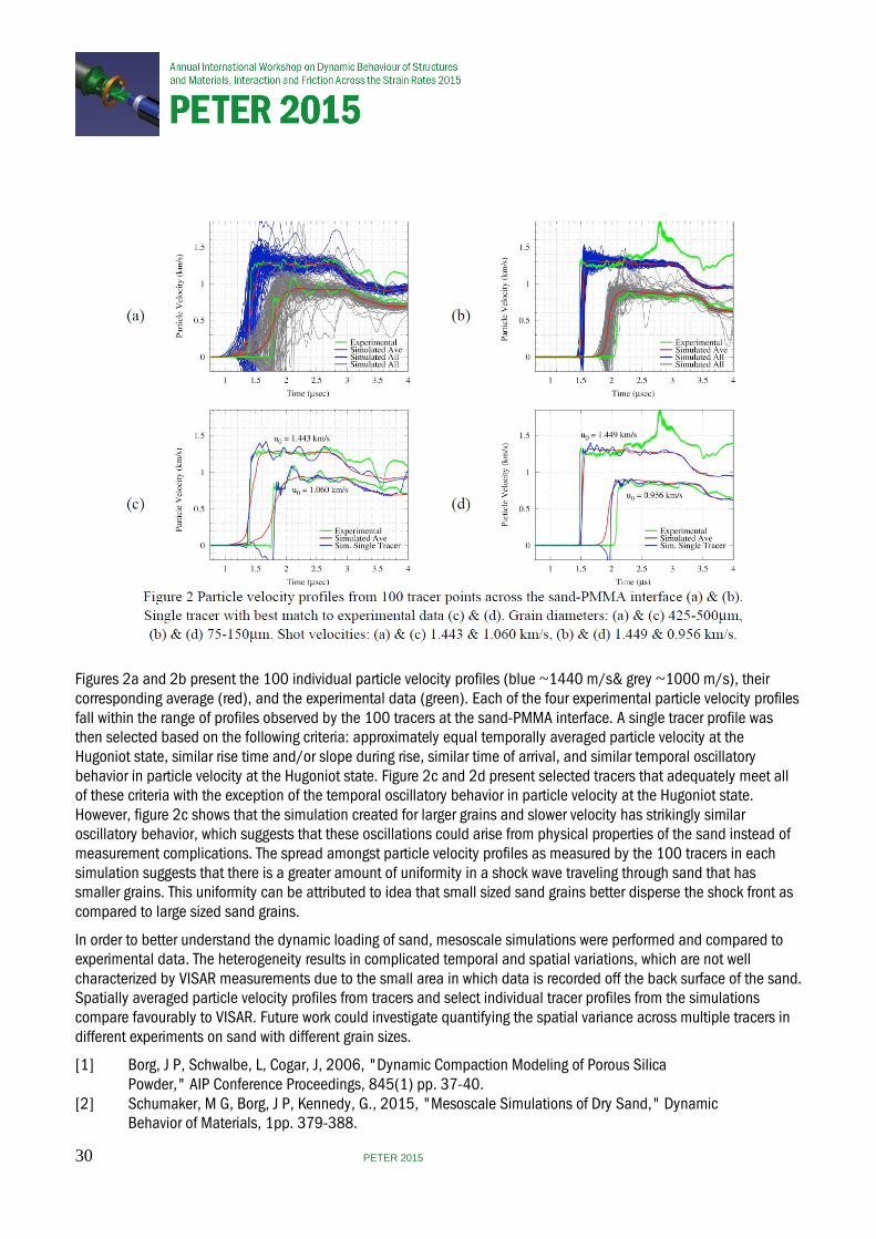
Figures 2a and 2b present the 100 individual particle velocity profiles (blue ~1440 m/s& grey ~1000 m/s), their corresponding average (red), and the experimental data (green). Each of the four experimental particle velocity profiles fall within the range of profiles observed by the 100 tracers at the sand-PMMA interface. A single tracer profile was then selected based on the following criteria: approximately equal temporally averaged particle velocity at the Hugoniot state, similar rise time and/or slope during rise, similar time of arrival, and similar temporal oscillatory behavior in particle velocity at the Hugoniot state. Figure 2c and 2d present selected tracers that adequately meet all of these criteria with the exception of the temporal oscillatory behavior in particle velocity at the Hugoniot state. However, figure 2c shows that the simulation created for larger grains and slower velocity has strikingly similar oscillatory behavior, which suggests that these oscillations could arise from physical properties of the sand instead of measurement complications. The spread amongst particle velocity profiles as measured by the 100 tracers in each simulation suggests that there is a greater amount of uniformity in a shock wave traveling through sand that has smaller grains. This uniformity can be attributed to idea that small sized sand grains better disperse the shock front as compared to large sized sand grains.
In order to better understand the dynamic loading of sand, mesoscale simulations were performed and compared to experimental data. The heterogeneity results in complicated temporal and spatial variations, which are not well characterized by VISAR measurements due to the small area in which data is recorded off the back surface of the sand. Spatially averaged particle velocity profiles from tracers and select individual tracer profiles from the simulations compare favourably to VISAR. Future work could investigate quantifying the spatial variance across multiple tracers in different experiments on sand with different grain sizes.
[1] Borg, J P, Schwalbe, L, Cogar, J, 2006, "Dynamic Compaction Modeling of Porous Silica Powder," AIP Conference Proceedings, 845(1) pp. 37-40. [2] Schumaker, M G, Borg, J P, Kennedy, G., 2015, "Mesoscale Simulations of Dry Sand," Dynamic Behavior of Materials, 1pp. 379-388.
30 PETER 2015
The effect of moisture on the shock and release of silica sands
J I Perry, C H Braithwaite, N E Taylor and A P Jardine
University of Cambridge, UK
The behavior of granular systems underpins a wide range of fundamental and technological phenomena. However, the inherent complexity of granular systems has meant that despite sustained research efforts, identifying a complete theoretical description remains a substantial challenge[1]. As such, performing detailed empirical studies remains extremely important. To date, the shock compaction of dry sands has been studied in some detail[2-5], and recently we established an approach that also provided information about the subsequent released state[6, 7]. However, comparatively little is known about the changes that occur with varying levels of moisture. We report a series of plate impact experiments giving shock Hugoniot and release data for a well characterized sand at dry, 10% moist and fully saturated water contents. The results reveal unexpected phenomena, and we discuss the mechanisms underpinning these changes in behavior.
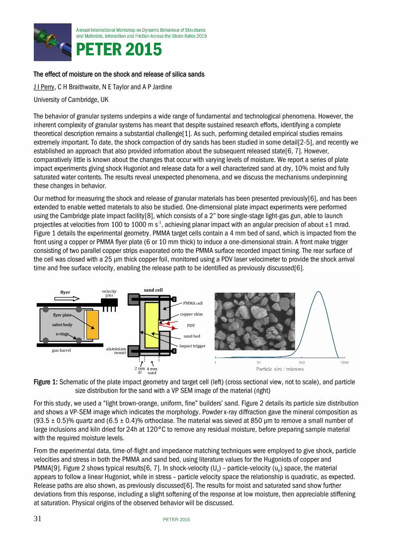
Our method for measuring the shock and release of granular materials has been presented previously[6], and has been extended to enable wetted materials to also be studied. One-dimensional plate impact experiments were performed using the Cambridge plate impact facility[8], which consists of a 2” bore single-stage light-gas gun, able to launch projectiles at velocities from 100 to 1000 m s-1, achieving planar impact with an angular precision of about ±1 mrad. Figure 1 details the experimental geometry. PMMA target cells contain a 4 mm bed of sand, which is impacted from the front using a copper or PMMA flyer plate (6 or 10 mm thick) to induce a one-dimensional strain. A front make trigger consisting of two parallel copper strips evaporated onto the PMMA surface recorded impact timing. The rear surface of the cell was closed with a 25 µm thick copper foil, monitored using a PDV laser velocimeter to provide the shock arrival time and free surface velocity, enabling the release path to be identified as previously discussed[6].
1 mm
Figure 1: Schematic of the plate impact geometry and target cell (left) (cross sectional view, not to scale), and particle size distribution for the sand with a VP SEM image of the material (right)
For this study, we used a “light brown-orange, uniform, fine” builders’ sand. Figure 2 details its particle size distribution and shows a VP-SEM image which indicates the morphology. Powder x-ray diffraction gave the mineral composition as (93.5 ± 0.5)% quartz and (6.5 ± 0.4)% orthoclase. The material was sieved at 850 µm to remove a small number of large inclusions and kiln dried for 24h at 120°C to remove any residual moisture, before preparing sample material with the required moisture levels.
From the experimental data, time-of-flight and impedance matching techniques were employed to give shock, particle velocities and stress in both the PMMA and sand bed, using literature values for the Hugoniots of copper and PMMA[9]. Figure 2 shows typical results[6, 7]. In shock-velocity (Us) – particle-velocity (up) space, the material appears to follow a linear Hugoniot, while in stress – particle velocity space the relationship is quadratic, as expected. Release paths are also shown, as previously discussed[6]. The results for moist and saturated sand show further deviations from this response, including a slight softening of the response at low moisture, then appreciable stiffening at saturation. Physical origins of the observed behavior will be discussed.
31 PETER 2015
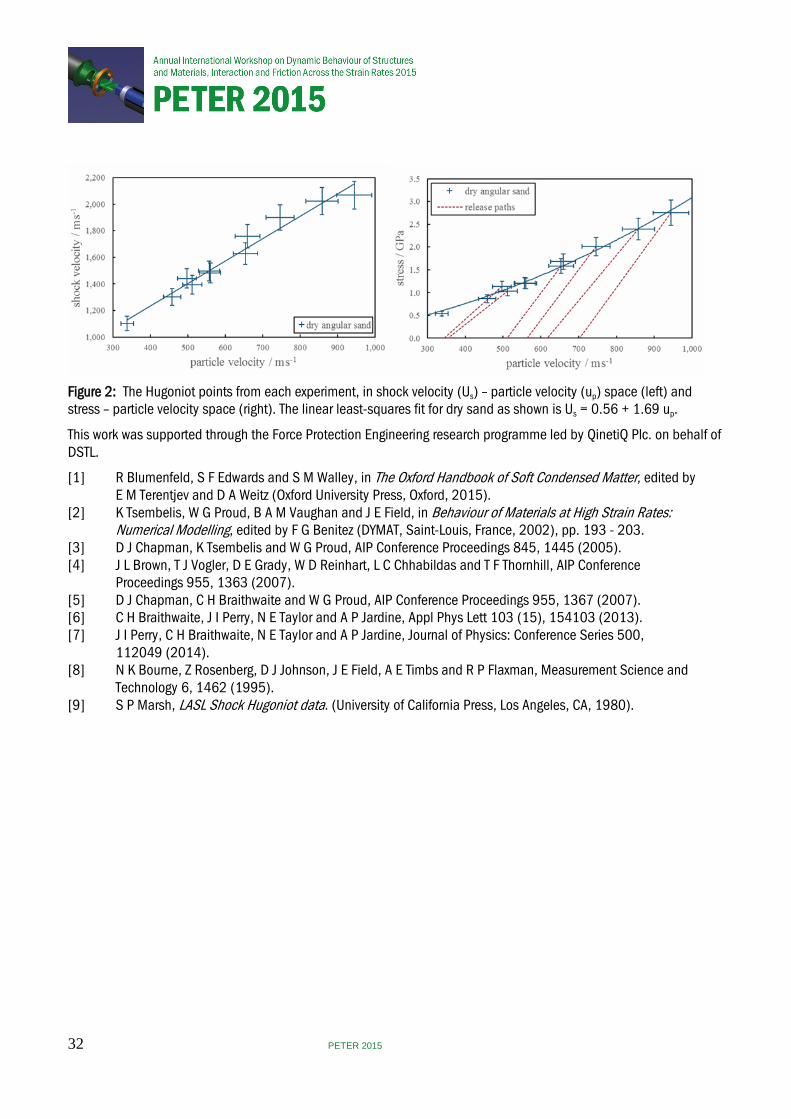
Figure 2: The Hugoniot points from each experiment, in shock velocity (Us) – particle velocity (up) space (left) and stress – particle velocity space (right). The linear least-squares fit for dry sand as shown is Us = 0.56 + 1.69 up.
This work was supported through the Force Protection Engineering research programme led by QinetiQ Plc. on behalf of DSTL.
[1] R Blumenfeld, S F Edwards and S M Walley, in The Oxford Handbook of Soft Condensed Matter, edited by E M Terentjev and D A Weitz (Oxford University Press, Oxford, 2015). [2] K Tsembelis, W G Proud, B A M Vaughan and J E Field, in Behaviour of Materials at High Strain Rates: Numerical Modelling, edited by F G Benitez (DYMAT, Saint-Louis, France, 2002), pp. 193 - 203. [3] D J Chapman, K Tsembelis and W G Proud, AIP Conference Proceedings 845, 1445 (2005). [4] J L Brown, T J Vogler, D E Grady, W D Reinhart, L C Chhabildas and T F Thornhill, AIP Conference Proceedings 955, 1363 (2007). [5] D J Chapman, C H Braithwaite and W G Proud, AIP Conference Proceedings 955, 1367 (2007). [6] C H Braithwaite, J I Perry, N E Taylor and A P Jardine, Appl Phys Lett 103 (15), 154103 (2013). [7] J I Perry, C H Braithwaite, N E Taylor and A P Jardine, Journal of Physics: Conference Series 500, 112049 (2014). [8] N K Bourne, Z Rosenberg, D J Johnson, J E Field, A E Timbs and R P Flaxman, Measurement Science and Technology 6, 1462 (1995). [9] S P Marsh, LASL Shock Hugoniot data. (University of California Press, Los Angeles, CA, 1980).
32 PETER 2015
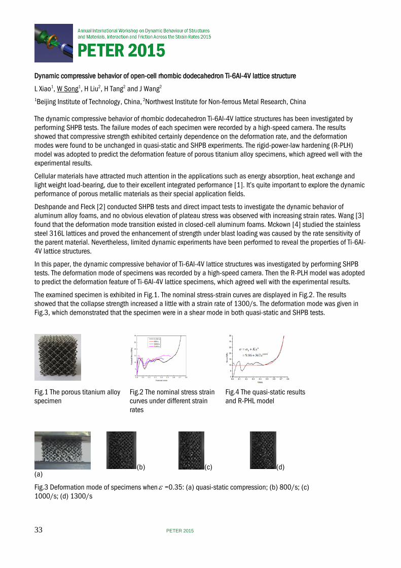
Dynamic compressive behavior of open-cell rhombic dodecahedron Ti-6Al-4V lattice structure
L Xiao1, W Song1, H Liu2, H Tang2 and J Wang2 1Beijing Institute of Technology, China, 2Northwest Institute for Non-ferrous Metal Research, China
The dynamic compressive behavior of rhombic dodecahedron Ti-6Al-4V lattice structures has been investigated by performing SHPB tests. The failure modes of each specimen were recorded by a high-speed camera. The results showed that compressive strength exhibited certainly dependence on the deformation rate, and the deformation modes were found to be unchanged in quasi-static and SHPB experiments. The rigid-power-law hardening (R-PLH) model was adopted to predict the deformation feature of porous titanium alloy specimens, which agreed well with the experimental results.
Cellular materials have attracted much attention in the applications such as energy absorption, heat exchange and light weight load-bearing, due to their excellent integrated performance [1]. It’s quite important to explore the dynamic performance of porous metallic materials as their special application fields.
Deshpande and Fleck [2] conducted SHPB tests and direct impact tests to investigate the dynamic behavior of aluminum alloy foams, and no obvious elevation of plateau stress was observed with increasing strain rates. Wang [3] found that the deformation mode transition existed in closed-cell aluminum foams. Mckown [4] studied the stainless steel 316L lattices and proved the enhancement of strength under blast loading was caused by the rate sensitivity of the parent material. Nevertheless, limited dynamic experiments have been performed to reveal the properties of Ti-6Al-4V lattice structures.
In this paper, the dynamic compressive behavior of Ti-6Al-4V lattice structures was investigated by performing SHPB tests. The deformation mode of specimens was recorded by a high-speed camera. Then the R-PLH model was adopted to predict the deformation feature of Ti-6Al-4V lattice specimens, which agreed well with the experimental results.
The examined specimen is exhibited in Fig.1. The nominal stress-strain curves are displayed in Fig.2. The results showed that the collapse strength increased a little with a strain rate of 1300/s. The deformation mode was given in Fig.3, which demonstrated that the specimen were in a shear mode in both quasi-static and SHPB tests.
Fig.1 The porous titanium alloy specimen
Fig.2 The nominal stress strain curves under different strain rates
Fig.4 The quasi-static results and R-PHL model
(a) (b) (c) (d)
Fig.3 Deformation mode of specimens whenε =0.35: (a) quasi-static compression; (b) 800/s; (c) 1000/s; (d) 1300/s
33 PETER 2015
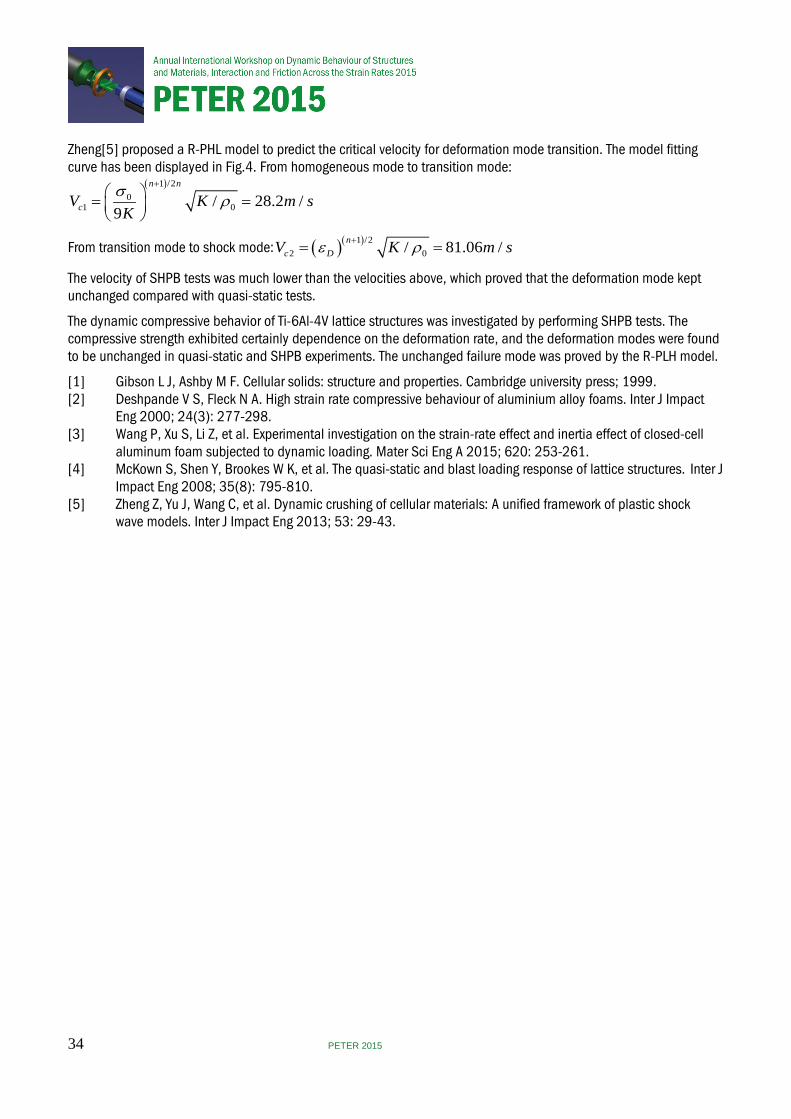
Zheng[5] proposed a R-PHL model to predict the critical velocity for deformation mode transition. The model fitting curve has been displayed in Fig.4. From homogeneous mode to transition mode:
( )1 /20
1 0/ 28.2 /9
n n
cV K m sKs ρ
+ = =
From transition mode to shock mode: ( )( )1 /22 0/ 81.06 /n
c DV K m sε ρ+= =
The velocity of SHPB tests was much lower than the velocities above, which proved that the deformation mode kept unchanged compared with quasi-static tests.
The dynamic compressive behavior of Ti-6Al-4V lattice structures was investigated by performing SHPB tests. The compressive strength exhibited certainly dependence on the deformation rate, and the deformation modes were found to be unchanged in quasi-static and SHPB experiments. The unchanged failure mode was proved by the R-PLH model.
[1] Gibson L J, Ashby M F. Cellular solids: structure and properties. Cambridge university press; 1999. [2] Deshpande V S, Fleck N A. High strain rate compressive behaviour of aluminium alloy foams. Inter J Impact Eng 2000; 24(3): 277-298. [3] Wang P, Xu S, Li Z, et al. Experimental investigation on the strain-rate effect and inertia effect of closed-cell aluminum foam subjected to dynamic loading. Mater Sci Eng A 2015; 620: 253-261. [4] McKown S, Shen Y, Brookes W K, et al. The quasi-static and blast loading response of lattice structures. Inter J Impact Eng 2008; 35(8): 795-810. [5] Zheng Z, Yu J, Wang C, et al. Dynamic crushing of cellular materials: A unified framework of plastic shock wave models. Inter J Impact Eng 2013; 53: 29-43.
34 PETER 2015
High strain-rate thermomechanical measurements of adiabatic shear band formation
J Patten, T White and D Eakins
Imperial College London, UK
A method for in-situ full field thermomechanical measurement of adiabatic shear band (ASB) formation and development is presented. Utilising a custom 3-D digital image correlation (DIC) and reflectance thermometry system our method goes beyond traditional far field diagnostics such as gauges and sample recovery, allowing for a more direct comparison to crystal plasticity and finite element models.
Adiabatic shear bands form on the scale of 10-100 um, typically under high strain-rate (102 - 104s-1) loading conditions. To date measurement of the formation and evolution of these bands has previously been conducted on Kolsky bar experiments, utilising far-field techniques such as strain gauges and sample recovery. In particular these experiments often aim to capture shear band formation by halting the experiment during loading, this can lead to results which are often difficult to interpret due to sample release and is not necessarily representative of material structure under formation conditions.
While previous work has typically focussed on either temporal or spatial measurements, none-to-date have focussed on both. Here presented are the designs for three-dimensional digital image correlation combined with reflectance thermometry system specifically for high rate experiments. Used in conjunction with a Kolsky bar experiment, and utilising a top-hat sample morphology designed to promote shear band formation in a specific region, strain concentrations and temperature fluctuations will be imaged in high resolution.
Physics based engineered ignition modeling for novel structural materials
D N Bentz1, D A Shockey2, M J Barnard1 and E N Enig1
1Enig Associates, Inc. USA, 2SRI International, USA
Recent advances in Structural Reactive Materials (SRM)s have enabled the development of smaller energetic structures with equivalent or better output, when compared with today’s state-of-the-art, novel energetics. These advances have produced a need to develop experimental methods and measurements for safely and accurately extracting fundamental material properties from asmanufactured SRM components, using non-destructive evaluation (NDE) techniques. SRMs differ from conventional materials (i.e. steel and aluminum), in that the lethality of SRMs is a result of the combustion of small particles, requiring a fundamental understanding of the fracture characteristics. To tailor the effects on target, engineers need to control and understand the fragment size and distribution of SRMs. For example, small particles can produce distributed effects, while larger fragments can deliver longer-range effects, as shown in Fig. 1.
The challenge here is that these composite structures utilize manufacturing methods that produce final parts with geometries and/or thicknesses, which are not amenable to industry standards, for mechanical characterization. SRMs have taken on a few forms, over the years. In some instances, macroscale composite structures cannot be destructively sectioned into more standard size test specimens without detrimentally affecting the properties, resulting in inaccurate properties characterization. The energetic nature of these materials creates requirements for non-standard characterization equipment capable of mitigating safety hazards. To overcome these challenges, new methods that use NDE techniques are required. These methods should provide information regarding initial defect types and concentrations. [2]
Enig Associates, Inc (“ENIG”), together with internationally recognized damage kinetics experts at SRI International (“SRI”) (Menlo Park, CA), led by Dr. Donald Shockey, has taken a physics-based approach to develop a modeling methodology with predictive and inferential capabilities, to address the mechanical limits of reactive structural materials. These modelling methodologies use subcritical mechanical material responses (i.e. pre-reacted state that
35 PETER 2015
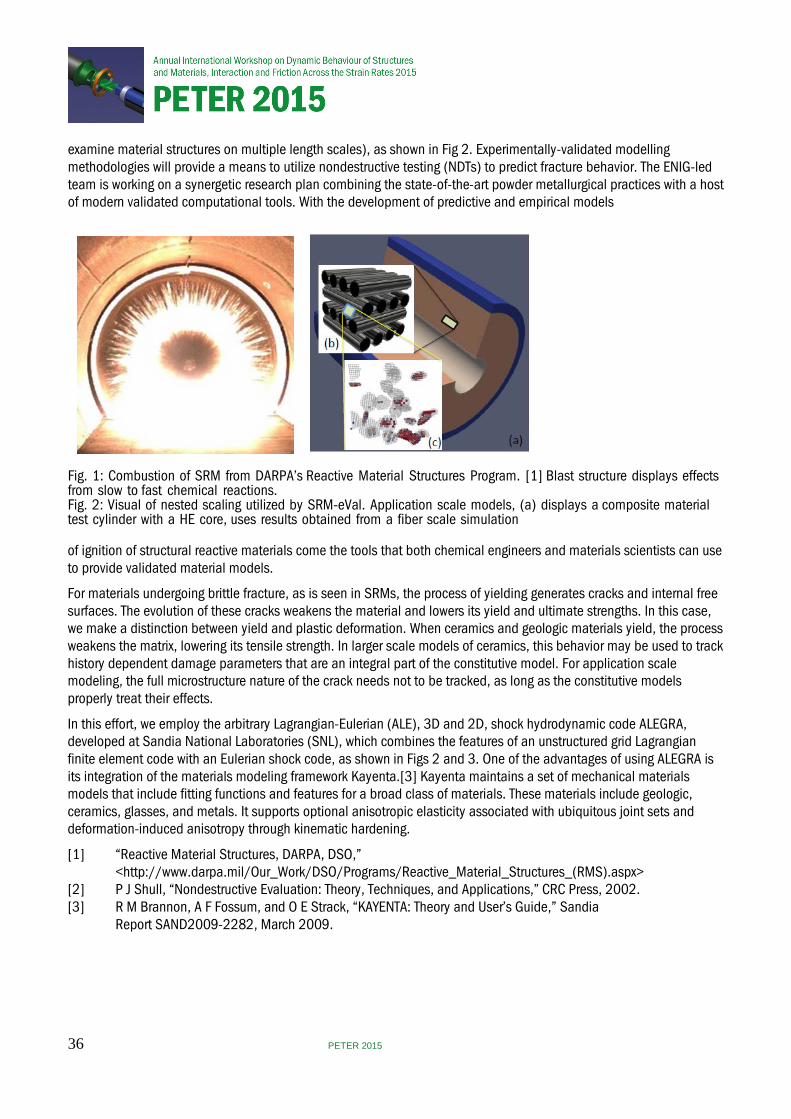
examine material structures on multiple length scales), as shown in Fig 2. Experimentally-validated modelling methodologies will provide a means to utilize nondestructive testing (NDTs) to predict fracture behavior. The ENIG-led team is working on a synergetic research plan combining the state-of-the-art powder metallurgical practices with a host of modern validated computational tools. With the development of predictive and empirical models
Fig. 1: Combustion of SRM from DARPA’s Reactive Material Structures Program. [1] Blast structure displays effects from slow to fast chemical reactions. Fig. 2: Visual of nested scaling utilized by SRM-eVal. Application scale models, (a) displays a composite material test cylinder with a HE core, uses results obtained from a fiber scale simulation
of ignition of structural reactive materials come the tools that both chemical engineers and materials scientists can use to provide validated material models.
For materials undergoing brittle fracture, as is seen in SRMs, the process of yielding generates cracks and internal free surfaces. The evolution of these cracks weakens the material and lowers its yield and ultimate strengths. In this case, we make a distinction between yield and plastic deformation. When ceramics and geologic materials yield, the process weakens the matrix, lowering its tensile strength. In larger scale models of ceramics, this behavior may be used to track history dependent damage parameters that are an integral part of the constitutive model. For application scale modeling, the full microstructure nature of the crack needs not to be tracked, as long as the constitutive models properly treat their effects.
In this effort, we employ the arbitrary Lagrangian-Eulerian (ALE), 3D and 2D, shock hydrodynamic code ALEGRA, developed at Sandia National Laboratories (SNL), which combines the features of an unstructured grid Lagrangian finite element code with an Eulerian shock code, as shown in Figs 2 and 3. One of the advantages of using ALEGRA is its integration of the materials modeling framework Kayenta.[3] Kayenta maintains a set of mechanical materials models that include fitting functions and features for a broad class of materials. These materials include geologic, ceramics, glasses, and metals. It supports optional anisotropic elasticity associated with ubiquitous joint sets and deformation-induced anisotropy through kinematic hardening.
[1] “Reactive Material Structures, DARPA, DSO,” <http://www.darpa.mil/Our_Work/DSO/Programs/Reactive_Material_Structures_(RMS).aspx> [2] P J Shull, “Nondestructive Evaluation: Theory, Techniques, and Applications,” CRC Press, 2002. [3] R M Brannon, A F Fossum, and O E Strack, “KAYENTA: Theory and User’s Guide,” Sandia Report SAND2009-2282, March 2009.
36 PETER 2015

Fig. 3: Example crack growth model in ALEGRA-MHD performed by ENIG. Cracks nucleated with pre damaged regions shown in (a) and (b) with highlighted cells. Cracking behavior developed from a pure shear strain evolving from (a) to (c), and pure tensile stain evolving from (b) to (d).
Experimental punching technique for ductile fracture testing on aluminium sheets
D García-González1, I Funes-Vecinoa1, M Rodríguez-Millánb1, A Rusinek2 and A Ariasa1 1University Carlos III of Madrid, Spain, 2National Engineering School of Metz, France
In recent years, many engineering fields require a comprehensive study of the behaviour of metal alloys with the fundamental requirements of lightweight properties and structural integrity. In particular, aluminium alloys are being widely introduced for building automobile and aircraft structures [1,2]. Thus, a exhaustive effort has been applied in order to conduct stress analysis and perform failure predictions on complex structures. This makes necessary to study the fracture phenomena of metals under different load conditions in order to propose accurate fracture criterion. Recent work on quasi-static fracture has shown that the dependence of ductility on the stress triaxiality and Lode parameter must be accounted for, but this dependence has not been investigated in the dynamic conditions. In this paper, punching experiments have been conducted on specimens of 2024 aluminium alloy using a high energy drop weight tower system CEAST INSTRON 9300. The experimental procedure covers an impact energy range from 1.71 J to 70.44 J. The thin aluminium sheet is clamped into a circular die and loaded in membrane tension through out-of-plane punching. The state of stress is changed from equi-biaxial to approximately uniaxial through the introduction of cut-outs in the sides of the specimen. A numerical model has been developed and validated with experimental data. This model allows a better understanding of punching experiments.
37 PETER 2015
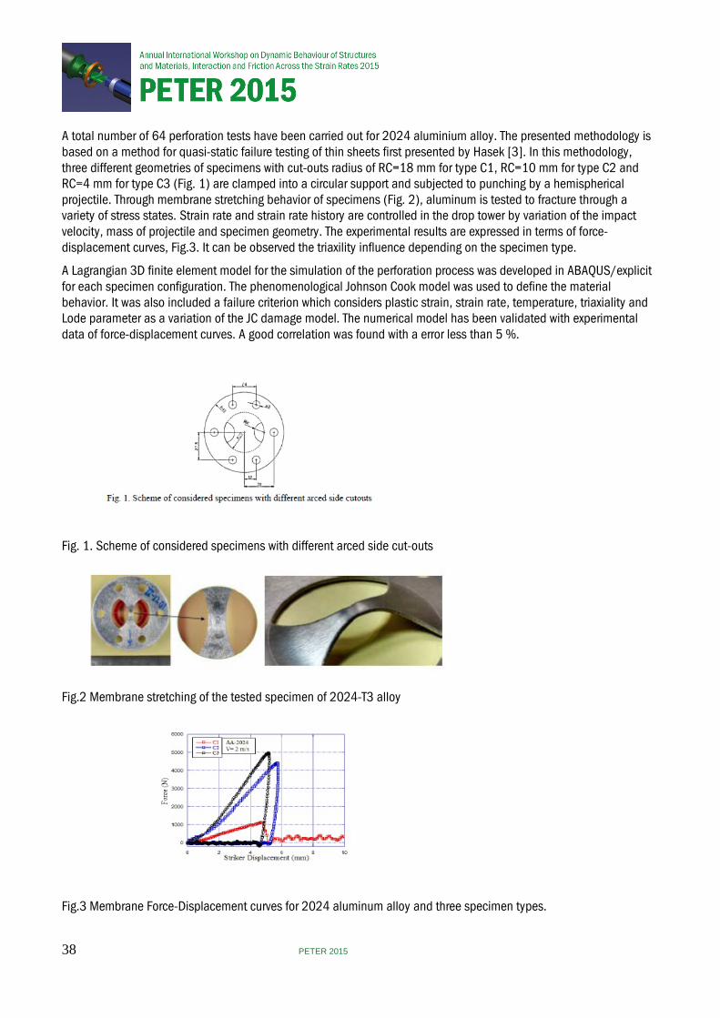
A total number of 64 perforation tests have been carried out for 2024 aluminium alloy. The presented methodology is based on a method for quasi-static failure testing of thin sheets first presented by Hasek [3]. In this methodology, three different geometries of specimens with cut-outs radius of RC=18 mm for type C1, RC=10 mm for type C2 and RC=4 mm for type C3 (Fig. 1) are clamped into a circular support and subjected to punching by a hemispherical projectile. Through membrane stretching behavior of specimens (Fig. 2), aluminum is tested to fracture through a variety of stress states. Strain rate and strain rate history are controlled in the drop tower by variation of the impact velocity, mass of projectile and specimen geometry. The experimental results are expressed in terms of force-displacement curves, Fig.3. It can be observed the triaxility influence depending on the specimen type.
A Lagrangian 3D finite element model for the simulation of the perforation process was developed in ABAQUS/explicit for each specimen configuration. The phenomenological Johnson Cook model was used to define the material behavior. It was also included a failure criterion which considers plastic strain, strain rate, temperature, triaxiality and Lode parameter as a variation of the JC damage model. The numerical model has been validated with experimental data of force-displacement curves. A good correlation was found with a error less than 5 %.
Fig. 1. Scheme of considered specimens with different arced side cut-outs
Fig.2 Membrane stretching of the tested specimen of 2024-T3 alloy
Fig.3 Membrane Force-Displacement curves for 2024 aluminum alloy and three specimen types.
38 PETER 2015
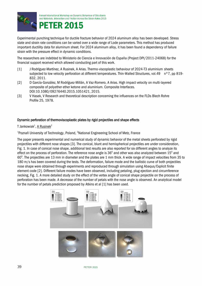
Experimental punching technique for ductile fracture behavior of 2024 aluminum alloy has been developed. Stress state and strain rate conditions can be varied over a wide range of Lode parameters. This method has produced important ductility data for aluminum sheet. For 2024 aluminum alloy, it has been found a dependency of failure strain with the pressure effect in dynamic conditions.
The researchers are indebted to Ministerio de Ciencia e Innovación de España (Project DPI/2011-24068) for the financial support received which allowed conducting part of this work.
[1] J Rodríguez-Martínez, A Rusinek, A Arias. Thermo-viscoplastic behaviour of 2024-T3 aluminium sheets subjected to low velocity perforation at different temperatures. Thin-Walled Structures, vol.49 nº7, pp 819- 832, 2011. [2] D García-González, M Rodríguez-Millán, A Vaz-Romero, A Arias. High impact velocity on multi-layered composite of polyether ether ketone and aluminium. Composite Interfaces. DOI:10.1080/09276440.2015.1051421, 2015. [3] V Hasek, V Research and theoretical description concerning the influences on the FLDs Blech Rohre Profile 25, 1978.
Dynamic perforation of thermoviscoplastic plates by rigid projectiles and shape effects
T Jankowiak1, A Rusinek2
1Poznañ University of Technology, Poland, 2National Engineering School of Metz, France
The paper presents experimental and numerical study of dynamic behavior of the metal sheets perforated by rigid projectiles with different nose shapes [3]. The conical, blunt and hemispherical projectiles are under consideration, Fig. 1. In case of conical nose shape, additional test results are also reported for six different angles to analyze its effect on the process of perforation. The reference nose angle is 360 and other was also analyzed between 150 and 600. The projectiles are 13 mm in diameter and the plates are 1 mm thick. A wide range of impact velocities from 35 to 180 m/s has been covered during the tests. The deformation, failure mode and the ballistic curve of both projectiles nose shape were obtained through experiments and reproduced through simulation using Abaqus/Explicit finite element code [2]. Different failure modes have been observed, including petaling, plug ejection and circumference necking, Fig. 1. A more detailed study on the effect of the vertex angle of conical shape projectile on the process of perforation has been made. A decrease of the number of petals with the nose angle is observed. An analytical model for the number of petals prediction proposed by Atkins et al [1] has been used.
39 PETER 2015

Fig. 1 Failure pattern for conical, hemispherical and blunt projectile shapes, V0=120 m/s
The paper presents also influence of the following aspects on the ballistic limit and ballistic curve: monolith and sandwich configurations, mass of projectiles, thickness of the metal sheets, the material yield stresses (different metals), strain hardening and strain rate hardening. The last one is analyzed for two constitutive models: with linear sensitivity (Johnson-Cook model) and nonlinear (Rusinek-Klepaczko model). Additionally, the impact force is also analyzed in details [4] in coupling with an energy balance [3].
[1] Atkins A G, Afzal Khan M, M Liu J H, Necking and radial cracking around perforations in thin sheets at normal incidence, International Journal of Impact Engineering, 21, 6, 1998, 521-539 [2] Jankowiak T, Rusinek A, Wood P, A numerical analysis of the dynamic behaviour of sheet steel perforated by a conical projectile under ballistic conditions, Finite Elements in Analysis and Design, 65,2013, 39–49 [3] Kpenyigba K M, Jankowiak T, Rusinek A, Pesci R, Influence of projectile shape on dynamic behavior of steel sheet subjected to impact and perforation, Thin-Walled Structures 65 (2013) 93– 104 [4] Jankowiak T, Rusinek A, Kpenyigba K M, Pesci R., Ballistic behavior of steel sheet subjected to impact and perforation, Steel and Composite Structures, 16(6) (2014) 595-609
40 PETER 2015
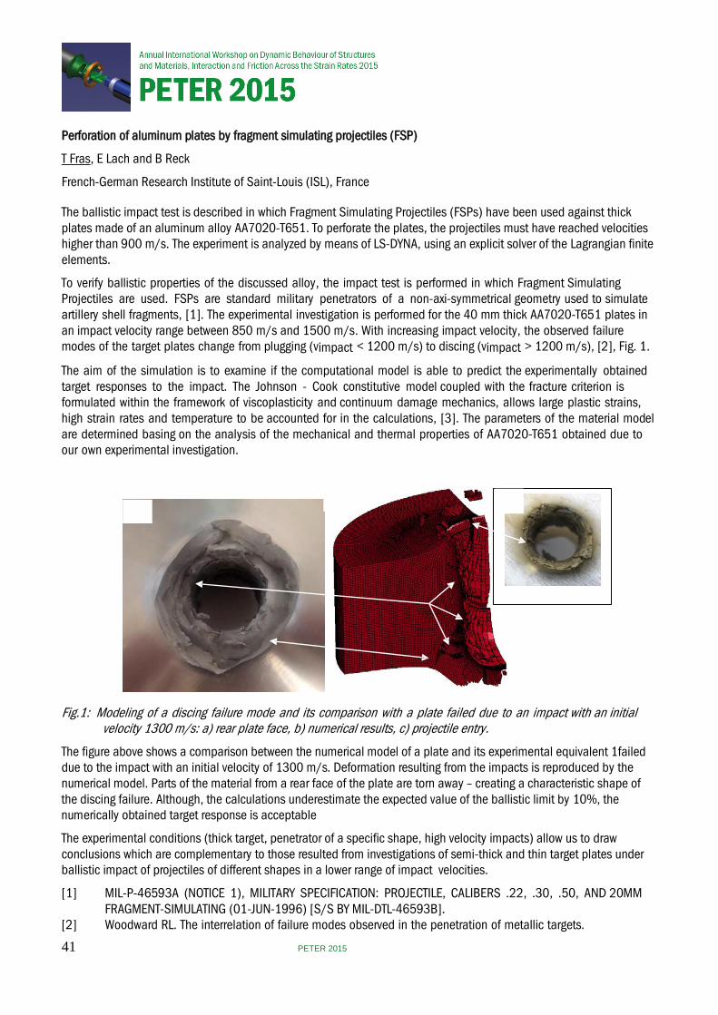
Perforation of aluminum plates by fragment simulating projectiles (FSP)
T Fras, E Lach and B Reck
French-German Research Institute of Saint-Louis (ISL), France
The ballistic impact test is described in which Fragment Simulating Projectiles (FSPs) have been used against thick plates made of an aluminum alloy AA7020-T651. To perforate the plates, the projectiles must have reached velocities higher than 900 m/s. The experiment is analyzed by means of LS-DYNA, using an explicit solver of the Lagrangian finite elements.
To verify ballistic properties of the discussed alloy, the impact test is performed in which Fragment Simulating Projectiles are used. FSPs are standard military penetrators of a non-axi-symmetrical geometry used to simulate artillery shell fragments, [1]. The experimental investigation is performed for the 40 mm thick AA7020-T651 plates in an impact velocity range between 850 m/s and 1500 m/s. With increasing impact velocity, the observed failure modes of the target plates change from plugging (vimpact < 1200 m/s) to discing (vimpact > 1200 m/s), [2], Fig. 1.
The aim of the simulation is to examine if the computational model is able to predict the experimentally obtained target responses to the impact. The Johnson - Cook constitutive model coupled with the fracture criterion is formulated within the framework of viscoplasticity and continuum damage mechanics, allows large plastic strains, high strain rates and temperature to be accounted for in the calculations, [3]. The parameters of the material model are determined basing on the analysis of the mechanical and thermal properties of AA7020-T651 obtained due to our own experimental investigation.
b) c)
a)
Fig.1: Modeling of a discing failure mode and its comparison with a plate failed due to an impact with an initial velocity 1300 m/s: a) rear plate face, b) numerical results, c) projectile entry.
The figure above shows a comparison between the numerical model of a plate and its experimental equivalent 1failed due to the impact with an initial velocity of 1300 m/s. Deformation resulting from the impacts is reproduced by the numerical model. Parts of the material from a rear face of the plate are torn away – creating a characteristic shape of the discing failure. Although, the calculations underestimate the expected value of the ballistic limit by 10%, the numerically obtained target response is acceptable
The experimental conditions (thick target, penetrator of a specific shape, high velocity impacts) allow us to draw conclusions which are complementary to those resulted from investigations of semi-thick and thin target plates under ballistic impact of projectiles of different shapes in a lower range of impact velocities.
[1] MIL-P-46593A (NOTICE 1), MILITARY SPECIFICATION: PROJECTILE, CALIBERS .22, .30, .50, AND 20MM FRAGMENT-SIMULATING (01-JUN-1996) [S/S BY MIL-DTL-46593B]. [2] Woodward RL. The interrelation of failure modes observed in the penetration of metallic targets.
41 PETER 2015
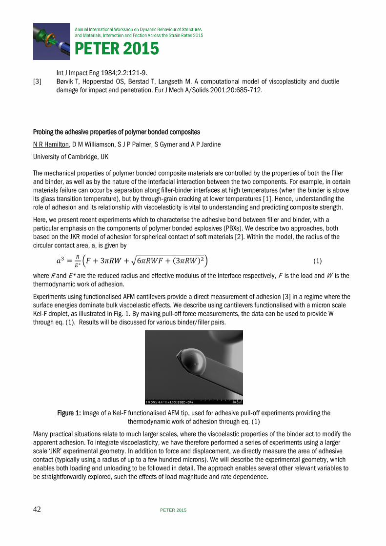
Int J Impact Eng 1984;2.2:121-9. [3] Børvik T, Hopperstad OS, Berstad T, Langseth M. A computational model of viscoplasticity and ductile damage for impact and penetration. Eur J Mech A/Solids 2001;20:685-712.
Probing the adhesive properties of polymer bonded composites
N R Hamilton, D M Williamson, S J P Palmer, S Gymer and A P Jardine
University of Cambridge, UK
The mechanical properties of polymer bonded composite materials are controlled by the properties of both the filler and binder, as well as by the nature of the interfacial interaction between the two components. For example, in certain materials failure can occur by separation along filler-binder interfaces at high temperatures (when the binder is above its glass transition temperature), but by through-grain cracking at lower temperatures [1]. Hence, understanding the role of adhesion and its relationship with viscoelasticity is vital to understanding and predicting composite strength.
Here, we present recent experiments which to characterise the adhesive bond between filler and binder, with a particular emphasis on the components of polymer bonded explosives (PBXs). We describe two approaches, both based on the JKR model of adhesion for spherical contact of soft materials [2]. Within the model, the radius of the circular contact area, a, is given by
𝑎𝑎3 = 𝑅𝑅𝐸𝐸∗�𝐹𝐹 + 3𝜋𝜋𝜋𝜋𝜋𝜋 + �6𝜋𝜋𝜋𝜋𝜋𝜋𝐹𝐹 + (3𝜋𝜋𝜋𝜋𝜋𝜋)2� (1)
where R and E* are the reduced radius and effective modulus of the interface respectively, F is the load and W is the thermodynamic work of adhesion.
Experiments using functionalised AFM cantilevers provide a direct measurement of adhesion [3] in a regime where the surface energies dominate bulk viscoelastic effects. We describe using cantilevers functionalised with a micron scale Kel-F droplet, as illustrated in Fig. 1. By making pull-off force measurements, the data can be used to provide W through eq. (1). Results will be discussed for various binder/filler pairs.
Figure 1: Image of a Kel-F functionalised AFM tip, used for adhesive pull-off experiments providing the
thermodynamic work of adhesion through eq. (1)
Many practical situations relate to much larger scales, where the viscoelastic properties of the binder act to modify the apparent adhesion. To integrate viscoelasticity, we have therefore performed a series of experiments using a larger scale ‘JKR’ experimental geometry. In addition to force and displacement, we directly measure the area of adhesive contact (typically using a radius of up to a few hundred microns). We will describe the experimental geometry, which enables both loading and unloading to be followed in detail. The approach enables several other relevant variables to be straightforwardly explored, such the effects of load magnitude and rate dependence.
42 PETER 2015
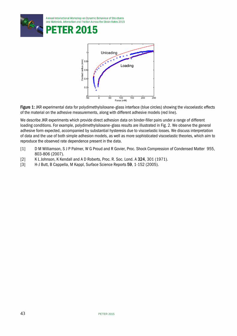
Figure 1: JKR experimental data for polydimethylsiloxane–glass interface (blue circles) showing the viscoelastic effects of the material on the adhesive measurements, along with different adhesive models (red line).
We describe JKR experiments which provide direct adhesion data on binder-filler pairs under a range of different loading conditions. For example, polydimethylsiloxane–glass results are illustrated in Fig. 2. We observe the general adhesive form expected, accompanied by substantial hysteresis due to viscoelastic losses. We discuss interpretation of data and the use of both simple adhesion models, as well as more sophisticated viscoelastic theories, which aim to reproduce the observed rate dependence present in the data.
[1] D M Williamson, S J P Palmer, W G Proud and R Govier, Proc. Shock Compression of Condensed Matter 955, 803-806 (2007). [2] K L Johnson, K Kendall and A D Roberts, Proc. R. Soc. Lond. A 324, 301 (1971). [3] H-J Butt, B Cappella, M Kappl, Surface Science Reports 59, 1-152 (2005).
43 PETER 2015
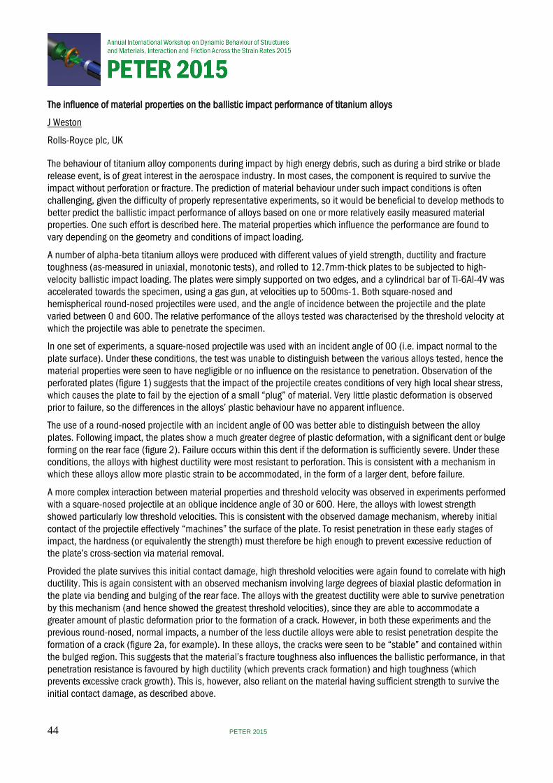
The influence of material properties on the ballistic impact performance of titanium alloys
J Weston
Rolls-Royce plc, UK
The behaviour of titanium alloy components during impact by high energy debris, such as during a bird strike or blade release event, is of great interest in the aerospace industry. In most cases, the component is required to survive the impact without perforation or fracture. The prediction of material behaviour under such impact conditions is often challenging, given the difficulty of properly representative experiments, so it would be beneficial to develop methods to better predict the ballistic impact performance of alloys based on one or more relatively easily measured material properties. One such effort is described here. The material properties which influence the performance are found to vary depending on the geometry and conditions of impact loading.
A number of alpha-beta titanium alloys were produced with different values of yield strength, ductility and fracture toughness (as-measured in uniaxial, monotonic tests), and rolled to 12.7mm-thick plates to be subjected to high-velocity ballistic impact loading. The plates were simply supported on two edges, and a cylindrical bar of Ti-6Al-4V was accelerated towards the specimen, using a gas gun, at velocities up to 500ms-1. Both square-nosed and hemispherical round-nosed projectiles were used, and the angle of incidence between the projectile and the plate varied between 0 and 60O. The relative performance of the alloys tested was characterised by the threshold velocity at which the projectile was able to penetrate the specimen.
In one set of experiments, a square-nosed projectile was used with an incident angle of 0O (i.e. impact normal to the plate surface). Under these conditions, the test was unable to distinguish between the various alloys tested, hence the material properties were seen to have negligible or no influence on the resistance to penetration. Observation of the perforated plates (figure 1) suggests that the impact of the projectile creates conditions of very high local shear stress, which causes the plate to fail by the ejection of a small “plug” of material. Very little plastic deformation is observed prior to failure, so the differences in the alloys’ plastic behaviour have no apparent influence.
The use of a round-nosed projectile with an incident angle of 0O was better able to distinguish between the alloy plates. Following impact, the plates show a much greater degree of plastic deformation, with a significant dent or bulge forming on the rear face (figure 2). Failure occurs within this dent if the deformation is sufficiently severe. Under these conditions, the alloys with highest ductility were most resistant to perforation. This is consistent with a mechanism in which these alloys allow more plastic strain to be accommodated, in the form of a larger dent, before failure.
A more complex interaction between material properties and threshold velocity was observed in experiments performed with a square-nosed projectile at an oblique incidence angle of 30 or 60O. Here, the alloys with lowest strength showed particularly low threshold velocities. This is consistent with the observed damage mechanism, whereby initial contact of the projectile effectively “machines” the surface of the plate. To resist penetration in these early stages of impact, the hardness (or equivalently the strength) must therefore be high enough to prevent excessive reduction of the plate’s cross-section via material removal.
Provided the plate survives this initial contact damage, high threshold velocities were again found to correlate with high ductility. This is again consistent with an observed mechanism involving large degrees of biaxial plastic deformation in the plate via bending and bulging of the rear face. The alloys with the greatest ductility were able to survive penetration by this mechanism (and hence showed the greatest threshold velocities), since they are able to accommodate a greater amount of plastic deformation prior to the formation of a crack. However, in both these experiments and the previous round-nosed, normal impacts, a number of the less ductile alloys were able to resist penetration despite the formation of a crack (figure 2a, for example). In these alloys, the cracks were seen to be “stable” and contained within the bulged region. This suggests that the material’s fracture toughness also influences the ballistic performance, in that penetration resistance is favoured by high ductility (which prevents crack formation) and high toughness (which prevents excessive crack growth). This is, however, also reliant on the material having sufficient strength to survive the initial contact damage, as described above.
44 PETER 2015
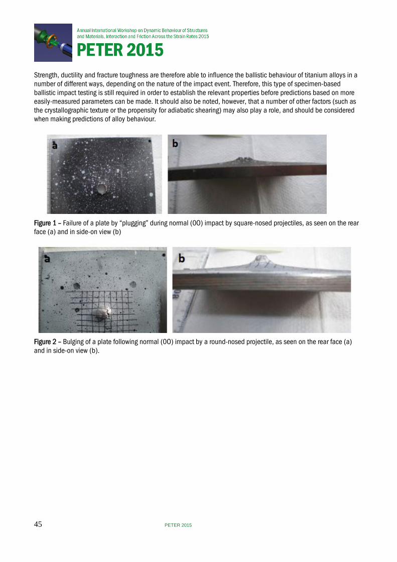
Strength, ductility and fracture toughness are therefore able to influence the ballistic behaviour of titanium alloys in a number of different ways, depending on the nature of the impact event. Therefore, this type of specimen-based ballistic impact testing is still required in order to establish the relevant properties before predictions based on more easily-measured parameters can be made. It should also be noted, however, that a number of other factors (such as the crystallographic texture or the propensity for adiabatic shearing) may also play a role, and should be considered when making predictions of alloy behaviour.
Figure 1 – Failure of a plate by “plugging” during normal (0O) impact by square-nosed projectiles, as seen on the rear face (a) and in side-on view (b)
Figure 2 – Bulging of a plate following normal (0O) impact by a round-nosed projectile, as seen on the rear face (a) and in side-on view (b).
45 PETER 2015
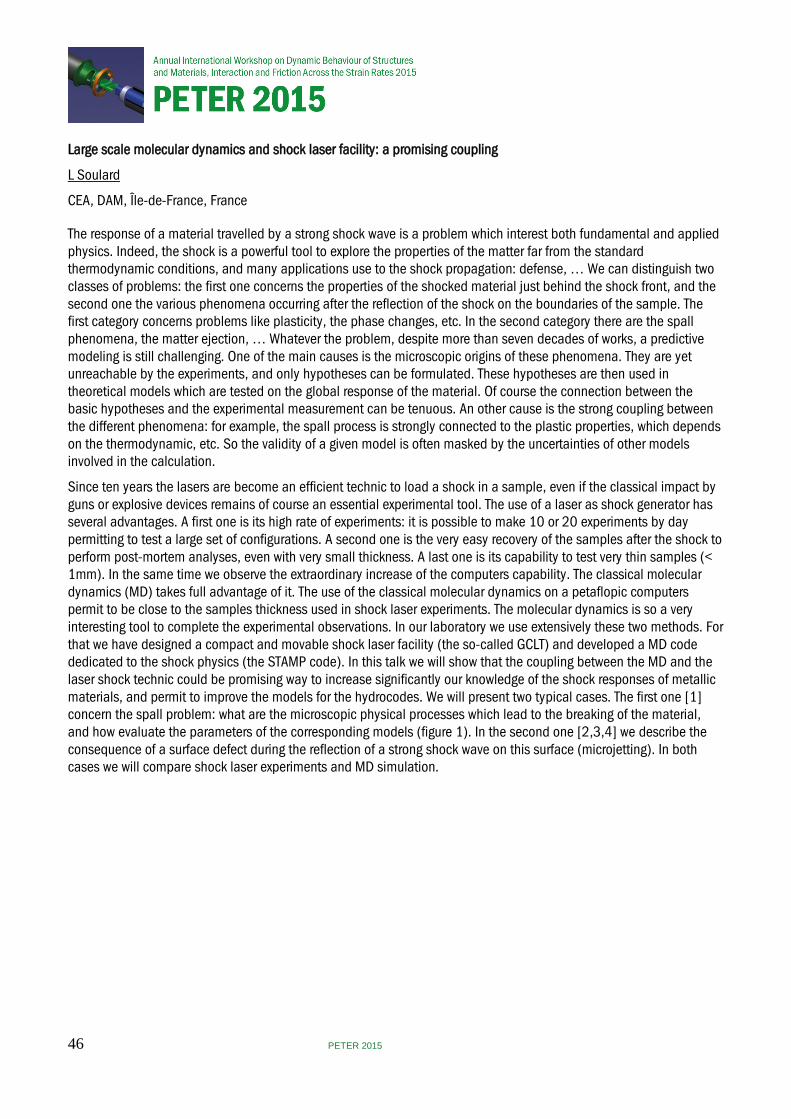
Large scale molecular dynamics and shock laser facility: a promising coupling
L Soulard
CEA, DAM, Île-de-France, France
The response of a material travelled by a strong shock wave is a problem which interest both fundamental and applied physics. Indeed, the shock is a powerful tool to explore the properties of the matter far from the standard thermodynamic conditions, and many applications use to the shock propagation: defense, … We can distinguish two classes of problems: the first one concerns the properties of the shocked material just behind the shock front, and the second one the various phenomena occurring after the reflection of the shock on the boundaries of the sample. The first category concerns problems like plasticity, the phase changes, etc. In the second category there are the spall phenomena, the matter ejection, … Whatever the problem, despite more than seven decades of works, a predictive modeling is still challenging. One of the main causes is the microscopic origins of these phenomena. They are yet unreachable by the experiments, and only hypotheses can be formulated. These hypotheses are then used in theoretical models which are tested on the global response of the material. Of course the connection between the basic hypotheses and the experimental measurement can be tenuous. An other cause is the strong coupling between the different phenomena: for example, the spall process is strongly connected to the plastic properties, which depends on the thermodynamic, etc. So the validity of a given model is often masked by the uncertainties of other models involved in the calculation.
Since ten years the lasers are become an efficient technic to load a shock in a sample, even if the classical impact by guns or explosive devices remains of course an essential experimental tool. The use of a laser as shock generator has several advantages. A first one is its high rate of experiments: it is possible to make 10 or 20 experiments by day permitting to test a large set of configurations. A second one is the very easy recovery of the samples after the shock to perform post-mortem analyses, even with very small thickness. A last one is its capability to test very thin samples (< 1mm). In the same time we observe the extraordinary increase of the computers capability. The classical molecular dynamics (MD) takes full advantage of it. The use of the classical molecular dynamics on a petaflopic computers permit to be close to the samples thickness used in shock laser experiments. The molecular dynamics is so a very interesting tool to complete the experimental observations. In our laboratory we use extensively these two methods. For that we have designed a compact and movable shock laser facility (the so-called GCLT) and developed a MD code dedicated to the shock physics (the STAMP code). In this talk we will show that the coupling between the MD and the laser shock technic could be promising way to increase significantly our knowledge of the shock responses of metallic materials, and permit to improve the models for the hydrocodes. We will present two typical cases. The first one [1] concern the spall problem: what are the microscopic physical processes which lead to the breaking of the material, and how evaluate the parameters of the corresponding models (figure 1). In the second one [2,3,4] we describe the consequence of a surface defect during the reflection of a strong shock wave on this surface (microjetting). In both cases we will compare shock laser experiments and MD simulation.
46 PETER 2015
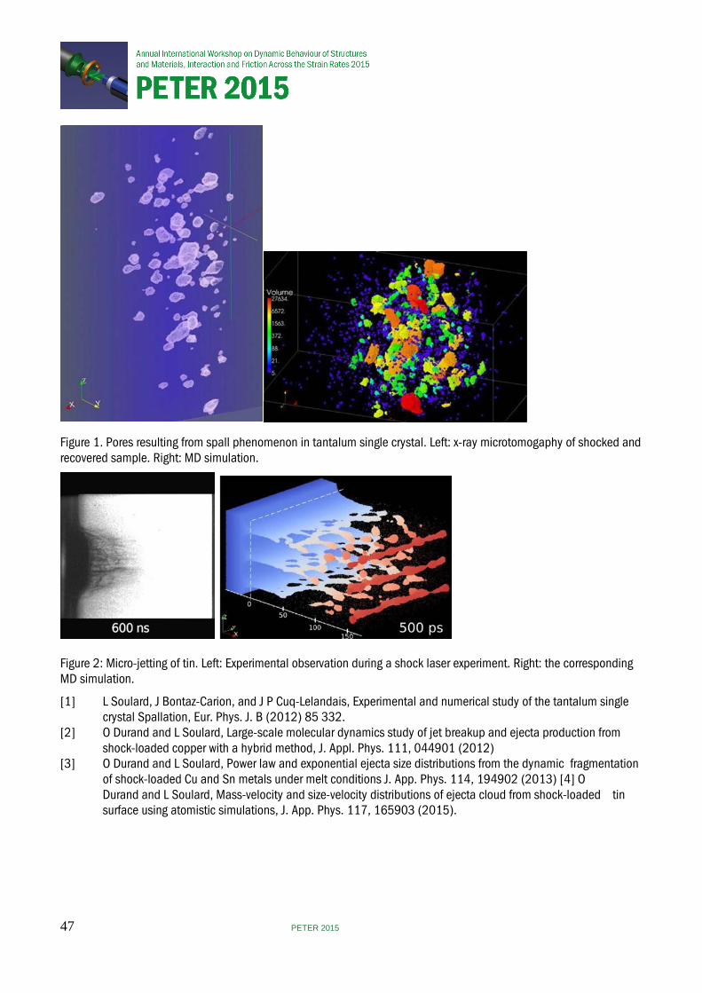
Figure 1. Pores resulting from spall phenomenon in tantalum single crystal. Left: x-ray microtomogaphy of shocked and recovered sample. Right: MD simulation.
Figure 2: Micro-jetting of tin. Left: Experimental observation during a shock laser experiment. Right: the corresponding MD simulation.
[1] L Soulard, J Bontaz-Carion, and J P Cuq-Lelandais, Experimental and numerical study of the tantalum single crystal Spallation, Eur. Phys. J. B (2012) 85 332. [2] O Durand and L Soulard, Large-scale molecular dynamics study of jet breakup and ejecta production from shock-loaded copper with a hybrid method, J. Appl. Phys. 111, 044901 (2012) [3] O Durand and L Soulard, Power law and exponential ejecta size distributions from the dynamic fragmentation of shock-loaded Cu and Sn metals under melt conditions J. App. Phys. 114, 194902 (2013) [4] O Durand and L Soulard, Mass-velocity and size-velocity distributions of ejecta cloud from shock-loaded tin surface using atomistic simulations, J. App. Phys. 117, 165903 (2015).
47 PETER 2015
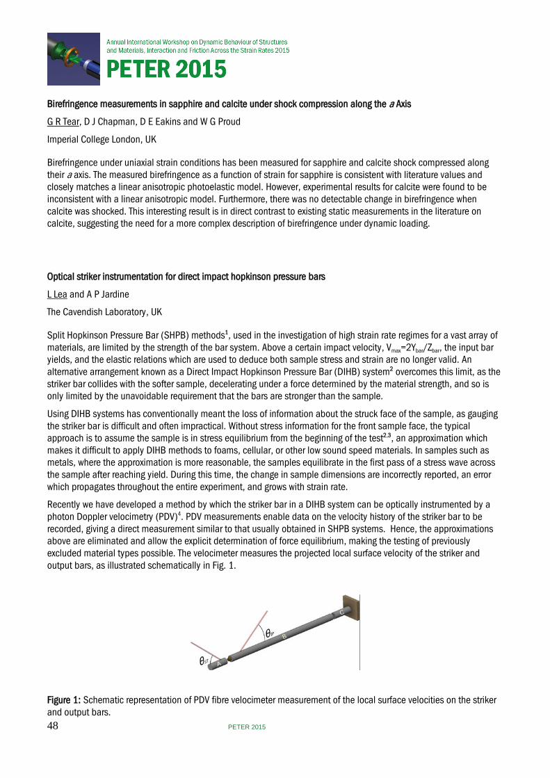
Birefringence measurements in sapphire and calcite under shock compression along the a Axis
G R Tear, D J Chapman, D E Eakins and W G Proud
Imperial College London, UK
Birefringence under uniaxial strain conditions has been measured for sapphire and calcite shock compressed along their a axis. The measured birefringence as a function of strain for sapphire is consistent with literature values and closely matches a linear anisotropic photoelastic model. However, experimental results for calcite were found to be inconsistent with a linear anisotropic model. Furthermore, there was no detectable change in birefringence when calcite was shocked. This interesting result is in direct contrast to existing static measurements in the literature on calcite, suggesting the need for a more complex description of birefringence under dynamic loading.
Optical striker instrumentation for direct impact hopkinson pressure bars
L Lea and A P Jardine
The Cavendish Laboratory, UK
Split Hopkinson Pressure Bar (SHPB) methods1, used in the investigation of high strain rate regimes for a vast array of materials, are limited by the strength of the bar system. Above a certain impact velocity, Vmax=2Ybar/Zbar, the input bar yields, and the elastic relations which are used to deduce both sample stress and strain are no longer valid. An alternative arrangement known as a Direct Impact Hopkinson Pressure Bar (DIHB) system2 overcomes this limit, as the striker bar collides with the softer sample, decelerating under a force determined by the material strength, and so is only limited by the unavoidable requirement that the bars are stronger than the sample.
Using DIHB systems has conventionally meant the loss of information about the struck face of the sample, as gauging the striker bar is difficult and often impractical. Without stress information for the front sample face, the typical approach is to assume the sample is in stress equilibrium from the beginning of the test2,3, an approximation which makes it difficult to apply DIHB methods to foams, cellular, or other low sound speed materials. In samples such as metals, where the approximation is more reasonable, the samples equilibrate in the first pass of a stress wave across the sample after reaching yield. During this time, the change in sample dimensions are incorrectly reported, an error which propagates throughout the entire experiment, and grows with strain rate.
Recently we have developed a method by which the striker bar in a DIHB system can be optically instrumented by a photon Doppler velocimetry (PDV)4. PDV measurements enable data on the velocity history of the striker bar to be recorded, giving a direct measurement similar to that usually obtained in SHPB systems. Hence, the approximations above are eliminated and allow the explicit determination of force equilibrium, making the testing of previously excluded material types possible. The velocimeter measures the projected local surface velocity of the striker and output bars, as illustrated schematically in Fig. 1.
Figure 1: Schematic representation of PDV fibre velocimeter measurement of the local surface velocities on the striker and output bars.
A
B
C
48 PETER 2015
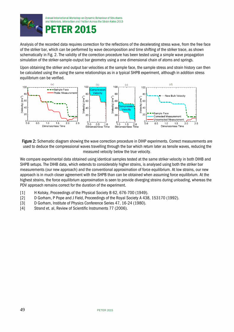
Analysis of the recorded data requires correction for the reflections of the decelerating stress wave, from the free face of the striker bar, which can be performed by wave decomposition and time shifting of the striker trace, as shown schematically in Fig. 2. The validity of the correction procedure has been tested using a simple wave propagation simulation of the striker-sample-output bar geometry using a one dimensional chain of atoms and springs.
Upon obtaining the striker and output bar velocities at the sample face, the sample stress and strain history can then be calculated using the using the same relationships as in a typical SHPB experiment, although in addition stress equilibrium can be verified.
Figure 2: Schematic diagram showing the wave correction procedure in DIHP experiments. Correct measurements are used to deduce the compressional waves travelling through the bar which return later as tensile waves, reducing the
measured velocity below the true velocity.
We compare experimental data obtained using identical samples tested at the same striker velocity in both DIHB and SHPB setups. The DIHB data, which extends to considerably higher strains, is analysed using both the striker bar measurements (our new approach) and the conventional approximation of force equilibrium. At low strains, our new approach is in much closer agreement with the SHPB than can be obtained when assuming force equilibrium. At the highest strains, the force equilibrium approximation is seen to provide diverging strains during unloading, whereas the PDV approach remains correct for the duration of the experiment.
[1] H Kolsky, Proceedings of the Physical Society B 62, 676-700 (1949). [2] D Gorham, P Pope and J Field, Proceedings of the Royal Society A 438, 153170 (1992). [3] D Gorham, Institute of Physics Conference Series 47, 16-24 (1980). [4] Strand et. al, Review of Scientific Instruments 77 (2006).
49 PETER 2015

On the development and validation of in vitro platform to investigate the response of cells over a wide range of pressure and strain-rates
D R Sory, H D Amin, S M Rankin and W G Proud
Imperial College London, UK
Increased interest in post-traumatic effects associated with blast wave exposure, such as traumatic brain injury and heterotopic ossification has led to more interest into how cells respond to dynamic mechanical loadings. It is well know that in a blast scenario, the high magnitudes of pressure and the rate of deformation experienced by the cells lead to acute damage that contribute to a wide range of deleterious effects on cellular functionalities and sometimes fatal outcomes on viability. Few researchers, however, have addressed the problem of how cells and their components respond to stress waves at pressure and strain rate approaching blast injury conditions. The objectives of this study are to introduce and validate a novel in vitro platform compatible with living cells to investigate the effects of high-pressure stress waves across a wide range of strain rates. Specifically, an hermetically sealed sample holder was designed to hold a 3D tissue construct during mechanical loading on three different mechanical loading devices. The sample holder was investigated as regards its abilities to fulfil both physical and biological requirements needed to ensure the transmission of the stress pulse through the entire system whilst keeping the biological material free of contamination. Multiaxial compression single pulse loading of periosteum stem cells embedded in hydrogel scaffold was performed at different magnitudes of stress under quasi-static, intermediate and high rate of loading. Post-pressurisation viability assay and sub-cellular components microscopy were performed in order to examine and correlate the cellular response after mechanical insult to the input mechanical loadings.
This work was conducted under the auspices of the Royal British Legion Centre for Blast Injury Studies at Imperial College London. The authors would like to acknowledge the financial support of the Royal British Legion.The Institute of Shock Physics acknowledges the support of AWE, Aldermaston, UK and Imperial College London.
50 PETER 2015

Investigations of blast mitigation structures using a shock tube system
T-T N Nguyen, T Davey, J M Wilgeroth and W G Proud
Imperial College London, UK
Blast injuries are very complex injuries that happen to both military personnel and civilians, especially in conflict zones. This study reports the use of an air-driven shock tube system to investigate the mitigations effects for primary blast injuries of various porous and granular structures. They are perforated sheets of different open area, reticulated foams with different thicknesses, granular beds of soda lime glass monospheres, and sandwich panels of perforated sheets with reticulated foams. The results are discussed in terms of pressure magnitudes, shock impulses and pulse shapes. Schlieren imaging was also used to aid the investigation. It was found that mitigation increased with decreasing open area of perforated sheets, decreased Carman-Kozeny permeability, increased bed length and increased particle diameter of the granular beds, as well as increasing foam thickness. The sandwich structure could achieve up to 95% in both pressure and impulse attenuations.
Use of pyrometry and optical emission spectroscopy to determine the temperature of explosive detonation products J Richley, T Ota and J Ferguson
AWE, UK
A combination of pyrometry and optical emission spectroscopy (OES) has been used to determine the temperature of the detonation products of a HMX based conventional high explosive. The temperature was measured at the end of a cylinder of explosive. The diagnostics observed the bare explosive through a lithium fluoride window. The temperature as a function of time was recorded using the pyrometer, while the OES produced a time integrated spectral measurement. The peak temperature was measured to be approximately 3700 K and fell to approximately 2400 K at the end of the measurement window. The OES measurement suggests that the emission from the detonation products could be approximated as a grey body with a corresponding temperature of between 3000 K and 3300 K.
51 PETER 2015
Fractional viscoplasticity for dynamic processes – non-normality and induced plastic anisotropy
W Sumelka1, M Nowak2, M Szymczyk1 and T Lodygowski1
1Poznañ University of Technology, Poland, 2Institute of Fundamental Technological Research of the Polish Academy of Sciences, Poland
In the presented discussion the application of the fractional viscoplasticity for description of dynamic processes is summarised. The considerations are focused on the non-normality of fractional viscoplastic flow and accompanying induced plastic anisotropy. The paper extends previous concepts [13, 14].
Reliable modelling of many metallic materials, in the framework of the theory of plasticity in- duces the necessary introduction of the non-associative flow rule concept [4, 1, 9, 15]. Concerning physical interpretation of the non-associativity in metallic materials one can mention about disloca- tion nucleation [16, 2, 11], nucleation of voids during plastic flow [8], or the breakup of grains into disoriented, blocky subgrains [6, 5, 12] (cf. review paper [9]). On the other hand another important fact from the experiment is an anisotropy induced by plastic deformation. Such an effect in metallic materials can occur together with phenomena governing the non-associativity [9].
For qualitative and quantitative modelling purposes the above mentioned experimental results should be taken into account in the model. It is clear that including both phenomena will necessarily increase the number of material parameters - but it always appears when making the phenomeno- logical model more precise [7, 3]. It is here where the concept of fractional viscoplasticity, being a generalisation of the classical one [10], shows its applicability and unusual flexibility. Finally, one should expect the approximation of experimental results to be easier with this new fractional flow rule concept - especially for materials which exhibit severe heterogeneity (e.g. multi-scale effects).
Dynamic tension of steel sheet will be presented as an illustrative example.
[1] F Barlat, D J Lege, and J C Brem. A six-component yield function for anisotropic materials.International Journal of Plasticity, 7:693–712, 1991. [2] M Dao and R J Asaro. Non-schmid effects and localized plastic flow in intermetallic alloys. Materials Science and Engineering: A, 170(1-2):143–160, 1993. [3] J Eftis, C. Carrasco, and R A Osegueda. A constitutive-microdamage model to simulate hyper- velocity
projectile-target impact, material damage and fracture. International Journal of Plastic- ity, 19:1321–1354, 2003.
[4] R Hill A theory of the yielding and plastic fow of anisotropic metals. Proceedings of the Royal Society A, 193:281–297, 1948.
[5] D A Hughes, Q Liu, D C Chrzan, and N Hansen. Scaling of microstructural parameters: Mis- orientations of deformation induced boundaries. Acta Materialia, 45(1):105–112, 199
52 PETER 2015
[6] T Leffers. Lattice rotations during plastic deformation with grain subdivision. Materials Science Forum, 157-
162:1815–1820, 1994. [7] T Lodygowski, A Rusinek, T Jankowiak, and W Sumelka. Selected topics of high speed ma- chining
analysis. Engineering Transactions, 60(1):69–96, 2012. [8] E B Marin and D L McDowell. Models for compressible elasto-plasticity based on internal state variables.
International Journal of Damage Mechanics, 7(1):47–83, 1998. [9] D L McDowell. Viscoplasticity of heterogeneous metallic materials. Materials Science and Engineering R,
62:67–123, 2008. [10] P Perzyna. The constitutive equations for rate sensitive plastic materials. Quarterly of Applied Mathematics,
20:321–332, 1963. [11] V Racherla and J L Bassani. Strain burst phenomena in the necking of a sheet that deforms by non-
associated plastic flow. Modelling and Simulation in Materials Science and Engineering, 15(1):S297– S311, 2007.
[12] P Steinmann, E Kuhl, and E Stein. Aspects of non-associated single crystal plasticity: Influence of non- schmid effects and localization analysis. International Journal of Solids and Structures, 35(33):4437– 4456, 1998.
[13] W Sumelka. Fractional viscoplasticity. Mechanics Research Communications, 56:31–36, 2014. [14] W Sumelka and M Nowak. Fractional calculus for plasticity - non-associativity and induced Plastic anisotropy. In 4th International Conference on Materials Modeling, Berkeley, California, May 27-29, 2015 2015. [15] A Taherizadeh, D E Green, and J W Yoon. Evaluation of advanced anisotropic models with mixed hardening
for general associated and non-associated flow metal plasticity. International Journal of Plasticity, 27(11):1781–1802, 2011.
[16] H Ziegler. An introduction to thermomechanics, volume 21 of North Holland Series in Applied Mathematics and Mechanics. North Holland, Amsterdam - New York, 1983.
Controllable high performance valves for improved crashworthiness of inflatable structures
P Pawłowski, C Graczykowski, M Ostrowski, K Sekuła and A Mróz
Polish Academy of Sciences, Poland
Energy absorbing pneumatic systems are mainly passive devices, which do not present ability of adaptation to various loading conditions. One of the most promising technology allowing for elimination of the abovementioned shortcomings are Adaptive Inflatable Structures (AIS cf. Refs. [1-2]), which form a new, special class of Adaptive Impact Absorption systems [3]. The proposed concept is based on application of compressed gas and controlling its pressure as an effective methodology allowing for adaptation of energy absorbing structures (airbags, fenders, barriers) to actual impact loading. Adaptive Inflatable Structures contain sealed chambers filled with compressed gas and equipped with controllable inflators and discharge valves. Pressure adjustment relies on appropriate initial inflation of particular chambers and control of the gas flow between the chambers and outside the structure during the process of deformation. Appropriate change of the actual value of pressure in different parts of the structure enables adaptation to dynamic loading of various energy, amplitude and location, however fast and efficient valves are required for optimal control. In many cases instead of a real-time control strategy it’s sufficient to apply a two stage sequence. At the beginning of the process valve remains closed providing fast rise of the pressure to the desired, optimal level. In the next step the valve opens, and subsequently the valve closes stabilizing the pressure level.
PETER 2015 53
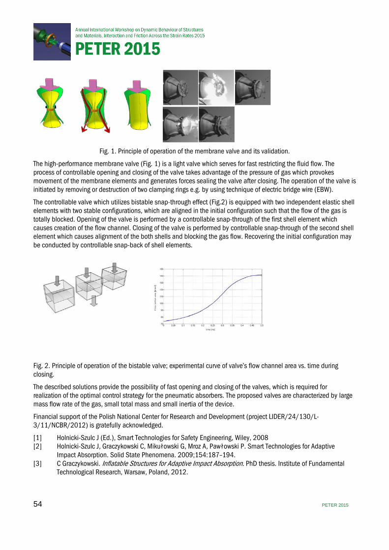
Fig. 1. Principle of operation of the membrane valve and its validation.
The high-performance membrane valve (Fig. 1) is a light valve which serves for fast restricting the fluid flow. The process of controllable opening and closing of the valve takes advantage of the pressure of gas which provokes movement of the membrane elements and generates forces sealing the valve after closing. The operation of the valve is initiated by removing or destruction of two clamping rings e.g. by using technique of electric bridge wire (EBW).
The controllable valve which utilizes bistable snap-through effect (Fig.2) is equipped with two independent elastic shell elements with two stable configurations, which are aligned in the initial configuration such that the flow of the gas is totally blocked. Opening of the valve is performed by a controllable snap-through of the first shell element which causes creation of the flow channel. Closing of the valve is performed by controllable snap-through of the second shell element which causes alignment of the both shells and blocking the gas flow. Recovering the initial configuration may be conducted by controllable snap-back of shell elements.
Fig. 2. Principle of operation of the bistable valve; experimental curve of valve’s flow channel area vs. time during closing.
The described solutions provide the possibility of fast opening and closing of the valves, which is required for realization of the optimal control strategy for the pneumatic absorbers. The proposed valves are characterized by large mass flow rate of the gas, small total mass and small inertia of the device.
Financial support of the Polish National Center for Research and Development (project LIDER/24/130/L-3/11/NCBR/2012) is gratefully acknowledged.
[1] Holnicki-Szulc J (Ed.), Smart Technologies for Safety Engineering, Wiley, 2008 [2] Holnicki-Szulc J, Graczykowski C, Mikułowski G, Mroz A, Pawłowski P. Smart Technologies for Adaptive Impact Absorption. Solid State Phenomena. 2009;154:187–194. [3] C Graczykowski. Inflatable Structures for Adaptive Impact Absorption. PhD thesis. Institute of Fundamental Technological Research, Warsaw, Poland, 2012.
54 PETER 2015
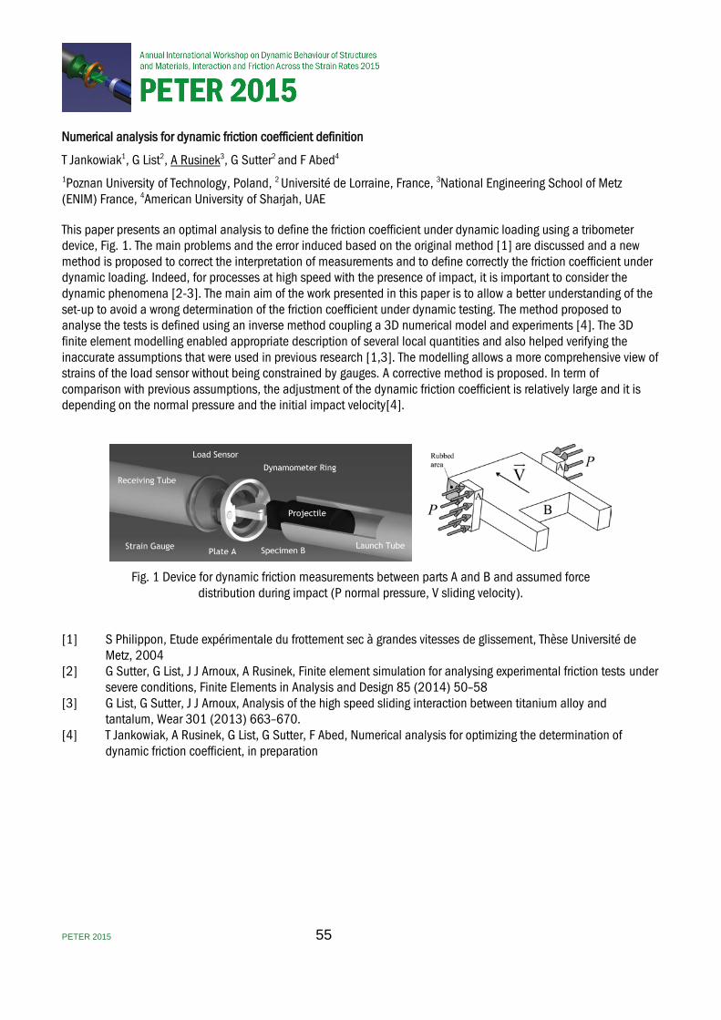
Numerical analysis for dynamic friction coefficient definition
T Jankowiak1, G List2, A Rusinek3, G Sutter2 and F Abed4
1Poznan University of Technology, Poland, 2 Université de Lorraine, France, 3National Engineering School of Metz (ENIM) France, 4American University of Sharjah, UAE
This paper presents an optimal analysis to define the friction coefficient under dynamic loading using a tribometer device, Fig. 1. The main problems and the error induced based on the original method [1] are discussed and a new method is proposed to correct the interpretation of measurements and to define correctly the friction coefficient under dynamic loading. Indeed, for processes at high speed with the presence of impact, it is important to consider the dynamic phenomena [2-3]. The main aim of the work presented in this paper is to allow a better understanding of the set-up to avoid a wrong determination of the friction coefficient under dynamic testing. The method proposed to analyse the tests is defined using an inverse method coupling a 3D numerical model and experiments [4]. The 3D finite element modelling enabled appropriate description of several local quantities and also helped verifying the inaccurate assumptions that were used in previous research [1,3]. The modelling allows a more comprehensive view of strains of the load sensor without being constrained by gauges. A corrective method is proposed. In term of comparison with previous assumptions, the adjustment of the dynamic friction coefficient is relatively large and it is depending on the normal pressure and the initial impact velocity[4].
Fig. 1 Device for dynamic friction measurements between parts A and B and assumed force distribution during impact (P normal pressure, V sliding velocity).
[1] S Philippon, Etude expérimentale du frottement sec à grandes vitesses de glissement, Thèse Université de Metz, 2004 [2] G Sutter, G List, J J Arnoux, A Rusinek, Finite element simulation for analysing experimental friction tests under severe conditions, Finite Elements in Analysis and Design 85 (2014) 50–58 [3] G List, G Sutter, J J Arnoux, Analysis of the high speed sliding interaction between titanium alloy and tantalum, Wear 301 (2013) 663–670. [4] T Jankowiak, A Rusinek, G List, G Sutter, F Abed, Numerical analysis for optimizing the determination of dynamic friction coefficient, in preparation
PETER 2015 55

Abstract Book
Institute of Physics76 Portland Place, London W1B 1NT, UK
Telephone: +44 (0)20 7470 4800Fax: +44 (0)20 7470 4848www.iop.org/conferences
Registered Charity Number: 293851