Embed Size (px)
Citation preview

L-Band and X-Band Antenna Design and Developmentfor NeXtRAD
S. T. Paine, P. Cheng, D. W. O’Hagan, M. R. Inggs, H. D. Griffiths*
Department of Electrical EngineeringRadar Remote Sensing GroupUniversity of Cape Town, SA
*Department of Electrical EngineeringUniversity College London, UK
Email: [email protected]
October 13, 2016
NeXtRAD Antenna University of Cape Town October 13, 2016 1 / 33

Outline
1 Project OutlineIntroductionNeXtRAD Node GeometryApplication Requirements
2 L-Band Antenna DesignL-Band Feed DesignL-Band Truncated Reflector DesignL-Band Prototype AntennaL-Band Antenna Results
3 X-Band Antenna DesignX-Band Feed DesignX-Band Horn DesignX-Band Prototype AntennaX-Band Antenna ResultsResults
4 Conclusions and Future Work
NeXtRAD Antenna University of Cape Town October 13, 2016 2 / 33

Introduction
NeXtRAD
In short, NeXtRAD is an evolution of NetRAD, a netted radar systemwhich operates in the S-Band.
NeXtRAD improves upon the RF capabilities of NetRAD by:
Fully Polaremetric (HH, HV, VV, VH)
Multiband (X- and L-Band)
Wireless networked nodes for large baseline separation
NeXtRAD Antenna University of Cape Town October 13, 2016 3 / 33

NeXtRAD
Figure: Basic NeXtRAD node geometry
NeXtRAD Antenna University of Cape Town October 13, 2016 4 / 33

Application Requirements
L- and X-Band Antenna Requirements
Dual polarised (Horizontal and Vertical)
L-Band centre frequency f0 = 1.3 GHz
X-Band centre frequency f0 = 8.5 GHz
Minimum 50 MHz bandwidth (X- and L-Band)
10° azimuth HPBW (X- and L-Band)
1.5 kW (L-Band) and 400 W (X-Band) peak power handlingcapabilities
Be able to be mounted on a standard tripod and withstand harshenvironmental conditions such as strong winds
NeXtRAD Antenna University of Cape Town October 13, 2016 5 / 33
L-Band Antenna Design
NeXtRAD Antenna University of Cape Town October 13, 2016 6 / 33

L-Band Coaxial to Waveguide Launcher Design
Freespace Wavelength:
λ0 = c/f =3 × 10⁸ m/s
1.3 × 10⁹Hz= 230.8 mm
Probe Length:
Lprobe =λ04
=C
4 × f0= 57.7 mm
Waveguide Wavelength:
λg =λ0√
1 − ( λ01.705×D )2
≈ 360 mm
Backshort Distance:
Lbackshort =λg4
≈ 90 mm
NeXtRAD Antenna University of Cape Town October 13, 2016 7 / 33

Coaxial to Waveguide Transition Design
Figure: Coaxial to waveguide transition.
NeXtRAD Antenna University of Cape Town October 13, 2016 8 / 33

L-Band Truncated Reflector Antenna
Required Specification Simulated ParameterDiameter 1440 mm
Height 744 mm
Depth 290.3 mm
Focal Point 446 mm
f/D ratio 0.31
Parabolic Equation y = (5.60 × 10−4)x2
H-Pol : 10.7°
HPBW (Azimuth)V-Pol : 10.0°
H-Pol : 16.4°
HPBW (Elevation)V-Pol : 16.6°
H-Pol : 20.3 dBSLL (Azimuth)
V-Pol : 16.9 dB
H-Pol : 15.1 dBSLL (Elevation)
V-Pol : 15.0 dB
H-Pol : 24.7 dBF/B ratio
V-Pol : 30.7 dB
NeXtRAD Antenna University of Cape Town October 13, 2016 9 / 33

Prototype L-Band Antenna Dimensions
NeXtRAD Antenna University of Cape Town October 13, 2016 10 / 33

Simulated Results of Modified Pre-fabricated Antenna
Parameter Simulated DesignDiameter 1350 mm
Height 600 mm
Depth 370 mm
Focal Point 307.85 mm
f /D ratio 0.23
Parabolic Equation y = (8.16 × 10−4)x2
HPBW (Az)H-Pol - 13.9°
V-Pol - 12.1°
HPBW (El)H-Pol - 19.7°
V-Pol - 20.5°
SLL (Az)H-Pol - 17.4 dBV-Pol - 17.4 dB
SLL (El)H-Pol - 16.3 dBV-Pol - 15.2 dB
F/B ratio 25 dB
NeXtRAD Antenna University of Cape Town October 13, 2016 11 / 33

L-Band Antenna Prototype
Figure: L-Band antenna prototype with dual polarised circular waveguide feed.
NeXtRAD Antenna University of Cape Town October 13, 2016 12 / 33

Optimised Feed Parameters
Due to feed blockage, physical adjustments were made to restorespecified performance.
The probe was moved forward inside the waveguide by 43.3 mm torestore required performance.
Parameter Standalone Feed Antenna with FeedProbe Length 57.7 mm 56.9 mm
Backshort Length 90.0 mm 133.3 mm
NeXtRAD Antenna University of Cape Town October 13, 2016 13 / 33

Dish with Feed S-Parameter Measurements
Figure: Simulated (blue) vs. Measured (red) S11 (top) S21 (middle) S22(bottom) parameters for optimised feed placed at the dish focal point.
NeXtRAD Antenna University of Cape Town October 13, 2016 14 / 33

L-Band Antenna Results
Figure: Testing setup on the roof of the Menzies and Snape buildings at UCT.
NeXtRAD Antenna University of Cape Town October 13, 2016 15 / 33

Beam Pattern Results for H-Pol
Figure: Horizontally polarised azimuth (Top) and elevation (Bottom) beampattern. (Left) Simulated (Right) Measured.
NeXtRAD Antenna University of Cape Town October 13, 2016 16 / 33

Beam Pattern Results for V-Pol
Figure: Vertically polarised azimuth (Top) and elevation (Bottom) beampattern. (Left) Simulated (Right) Measured.
NeXtRAD Antenna University of Cape Town October 13, 2016 17 / 33

Summary of L-Band Prototype Antenna Performance
Horizontal Polarisation Vertical PolarisationFEKO CST Measured FEKO CST Measured
Az HPBW 12.1° 12.2° 12.4° 13.9° 14.2° 13.9°
El HPBW 20.5° 20.4° 20.0° 19.7° 19.5° 19.6°
Az SLL -17.3 dB -17.0 dB -17.4 dB -17.4 dB -17.2 dB -16.4 dBEl SLL -15.2 dB -15.2 dB -15.7 dB -16.3 dB -16.9 dB -15.8 dB
NeXtRAD Antenna University of Cape Town October 13, 2016 18 / 33

L-Band Prototype Antenna Summary
It has been shown that:
The measured results of the built prototype match the simulatedresults as expected
A truncated parabolic dish antenna can meet all the applicationrequirements
Circular waveguides perform better than square waveguides when dualpolarising using orthogonal probes [1]
Feed blockage is of major concern with electrically small prime focusdish antennas (D ≤ 10λ0) [2]
NeXtRAD Antenna University of Cape Town October 13, 2016 19 / 33

X-Band Antenna Design
NeXtRAD Antenna University of Cape Town October 13, 2016 20 / 33

X-Band Coaxial to Waveguide Feed Design
X-Band Free-space wavelength for 8.5 GHz:
λ◦ =c
f◦=
3 × 10⁸ m/s
8.5 × 10⁹ Hz= 35.29 mm
Waveguide diameter (lg ) chosen from aluminium water pipe is 28 mm.Cutoff wavelength:
λc(TE11) = 1.706 × lg = 47.77 mm
Cutoff frequency is calculated to be 6.28 GHz. Length of the probe andbackshort:
Lprobe =λ◦4
= 8.82 mm
Lbackshort =λg4
= 13.09 mm
NeXtRAD Antenna University of Cape Town October 13, 2016 21 / 33

X-Band Horn Antenna
Figure: Side view of a horn antenna.
Diameter of the antenna aperture:
D =70λ◦θ
= 247.03 mm
Length of the horn from waveguide to aperture:
lh =D2
3λ◦
(1 − lg
D
)= 511.14 mm
NeXtRAD Antenna University of Cape Town October 13, 2016 22 / 33

X-Band Prototype Antenna
Figure: X-Band conical horn antenna prototype with the dual polarised waveguidefeed.
NeXtRAD Antenna University of Cape Town October 13, 2016 23 / 33

X-Band Antenna Results
Figure: Antenna configuration at Menzies Building rooftop.
NeXtRAD Antenna University of Cape Town October 13, 2016 24 / 33

Simulated X-Band Antenna S-Parameters
Figure: Simulated S-parameter results for X-Band horn antenna. S11 (blue), S12(red) and S22 (green) are shown.
NeXtRAD Antenna University of Cape Town October 13, 2016 25 / 33
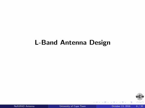
Measured X-Band Antenna S-Parameters
Figure: Measured S-parameter results for X-Band horn antenna. S11 (blue), S12(red) and S22 (green) are shown.
NeXtRAD Antenna University of Cape Town October 13, 2016 26 / 33

Simulated X-Band Antenna Radiation Patterns
Figure: Simulated X-Band antenna radiation patterns. Azimuth plane (green) andelevation plane(blue) for both V-pol (left) and H-pol (right).
NeXtRAD Antenna University of Cape Town October 13, 2016 27 / 33

Measured X-Band Antenna Radiation Patterns
Figure: Measured X-Band antenna radiation patterns. Azimuth plane (green) andelevation plane(blue) for both V-pol (left) and H-pol (right).
NeXtRAD Antenna University of Cape Town October 13, 2016 28 / 33

Summary of X-Band Antenna Prototype Performance
Horizontal Pol Vertical PolSimulated Measured Simulated Measured
Az HPBW 9.3° 9.1° 10.7° 10.4°
El HPBW 10.7° 10.0° 9.3° 9.2°
Az SLL -20.1 dB -23.8 dB -37.6 dB -35.9 dBEl SLL -37.7 dB -31.9 dB -20.1 dB -23.6 dB
NeXtRAD Antenna University of Cape Town October 13, 2016 29 / 33

X-Band Prototype Antenna Summary
It has been shown that:
Conical horn and circular waveguide met all the NeXtRAD’s antennaspecifications.
Manageable in size and portable.
Dual polarisation has been successfully implemented.
Approximately 10◦ azimuth HPBW achieved in both polarisations.
FEKO shows accuracy.
NeXtRAD Antenna University of Cape Town October 13, 2016 30 / 33

Conclusions and Future Work
The simulated results shown a close agreement to the measuredresults for both L- and X-Band prototypes.
The measured L-Band prototype has an azimuth HPBW of 12.4°and13.9°when horizontally and vertically polarised respectively.
The measured X-Band prototype has an azimuth HPBW of10.7°when both horizontally and vertically polarised.
With improved manufacturing, the optimal L-Band antenna can beproduced to provide almost exactly 10° azimuth HPBW as wassimulated.
It has been shown that both antennas meet the requirements and aresuitable for use in NeXtRAD.
NeXtRAD Antenna University of Cape Town October 13, 2016 31 / 33

References I
S. Paine, “Design and Implementation of Dual Polarised L-BandAntenna with 10 Degree Azimuth Beamwidth,” University of CapeTown, Cape Town, Tech. Rep., 2014.
P. Wade, “Parabolic Dish Feeds,” 1998, accessed: October 13, 2016.[Online]. Available: http://www.w1ghz.org/antbook/chap11.pdf
NeXtRAD Antenna University of Cape Town October 13, 2016 32 / 33

Thank you!
NeXtRAD Antenna University of Cape Town October 13, 2016 33 / 33