Embed Size (px)
Citation preview

LAB 2-4A EIGRP FRAME RELAY HUB AND SPOKE: ROUTER USED AS FRAME SWITCH
Sang-Gon LEEProf./Ph.DDivision of Computer and Information Engineering, Dongseo University,Director of Innovation Center for Engineering Education(ICEE).

OBJECTIVES Review basic configuration of EIGRP on a serial
interface Configure the bandwidth-percent command Configure EIGRP over Frame Relay hub and spoke Use EIGRP in non-broadcast mode Enable EIGRP manual summarization in topologies
with discontiguous major networks
TOPOLOGY
NOTE:-•Given the diversity of router models and the differing naming conventions for serial interfaces (S0, S0/0, S0/0/0),•The interface numbers on devices will probably differ from those in the topology diagram.
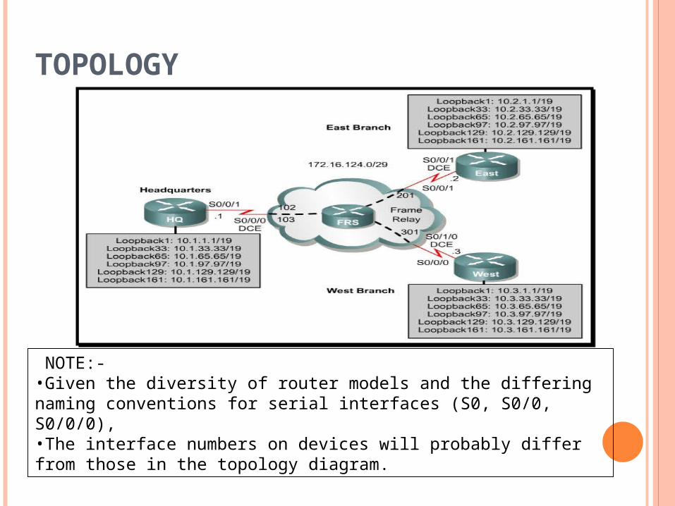
CONTD.. Always draw network diagram to reflect topology. If any uncertainty for DCE connection, then use the show
controllers serial interface_type interface_number command:
HQ# show controllers serial0/0/0
Interface Serial0/0/0
Hardware is GT96K
DCE V.35, clock rate 2000000
<output omitted>

SCENARIO
Suppose a company want to a new network between company Headquarter(HQ) , East, and west branches.
They are connected over hub and spoke Frame relay. company headquarter use as Hub.
Each network with multiple loopback interfaces on each router. EIGRP to allow full connectivity between all departments. To simulate the Frame Relay WAN connections. Use a router with three serial ports configured as a frame switch.

STEP 1: ADDRESSING
Apply IP addresses to the loopback interfaces on HQ, East, and West.
Paste the following configurations into routers to begin must be in configuration mode when do this.
HQ:!interface Loopback1ip address 10.1.1.1 255.255.224.0interface Loopback33ip address 10.1.33.1 255.255.224.0interface Loopback65ip address 10.1.65.1 255.255.224.0interface Loopback97ip address 10.1.97.1 255.255.224.0interface Loopback129ip address 10.1.129.1 255.255.224.0interface Loopback161ip address 10.1.161.1 255.255.224.0!end

CONTD..NOTE: all code is same just replace the only 1,
In each address. (HQ=1, East=2, West=3).
As Like: East:- ip address 10.2.1.1 255.255.224.0
West:- ip address 10.3.1.1 255.255.224.0 For now, the IP address is the only configuration on the serial
interfaces. Leave the serial interfaces with their default encapsulation (HDLC)

CONFIGURATIONS Recommendations are described in terms of configuring the
interface "bandwidth" parameter EIGRP being able to use 50 percent of that bandwidth by
default. Bandwidth configuration cannot be changed Bandwidth-percent command should be used to control
the EIGRP bandwidth On low-speed interfaces, raising the available bandwidth for
EIGRP above the default of 50 percent is advisable in order to improve convergence.

CONTD..
LAN Interfaces (Ethernet, Token Ring, FDDI) set by default to the actual media speed bandwidth is explicitly configured to a very low value.
Then need to configure. Point-to-Point Serial Interfaces (HDLC, PPP)
defaults to T1 speed (1.544 Mbps) on serial interfaces set to the actual link speed.
NBMA Interfaces (Frame Relay, X.25, ATM) particularly critical to configure nonbroadcast multi-
access (NBMA) interfaces correctly. otherwise many EIGRP packets may be lost in the
switched network.

CONTD.. Three basic rules
The traffic that EIGRP is allowed to send on a single virtual circuit (VC) cannot exceed the capacity of that VC.
The total EIGRP traffic for all virtual circuits cannot exceed the access line speed of the interface.
The bandwidth allowed for EIGRP on each virtual circuit must be the same in each direction
Three different scenarios for NBMA interfaces Pure Multipoint Configuration (no subinterfaces) Pure Point-to-Point Configuration (each VC on a separate
subinterface) Hybrid Configuration (point-to-point and multipoint
subinterfaces

PURE MULTIPOINT CONFIGURATION (NO SUBINTERFACES) EIGRP will divide the configured bandwidth evenly across
each virtual circuit. Must ensure that this will not overload each virtual circuit. For example:
if you have a T1 access line with four 56K VCs, you should configure the bandwidth to be 224Kbps (4 * 56Kbps) in order to avoid dropping packets. If the total bandwidth of the virtual circuits equals or exceeds the access line speed, configure the bandwidth to equal the access line speed. Note that if the virtual circuits are of different capacities, the bandwidth must be set to take into account the lowest capacity virtual circuit.
For instance, if a T1 access line has three 256Kbps VCs and one 56Kbps VC, the bandwidth should be set to 224Kbps (4 * 56Kbps). In such configurations, putting at least the slow virtual circuit onto a point-to-point subinterface is strongly recommended

PURE POINT-TO-POINT CONFIGURATION (EACH VC ON A SEPARATE SUBINTERFACE)
configuration allows maximum bandwidth control, since the bandwidth can be configured separately on each subinterface
virtual circuits have different capacities. It is best configuration.
total bandwidth for all subinterfaces cannot exceed the available access line bandwidth
If the interface is oversubscribed, the access line bandwidth must be divided across each of the subinterfaces
For Example:- if a T1 access line (1544 Kbps) has ten virtual circuits
with a capacity of 256Kbps, the bandwidth on each subinterface should be configured to be 154Kbps (1544/10) instead of 256Kbps each.

HYBRID CONFIGURATION (POINT-TO-POINT AND MULTIPOINT SUBINTERFACES)
combinations of the two individual strategies Examples :
Dotted Line :- corresponds to separate PVCColor: a separate IP subnet
• To set the interface bandwidth to reflect the PVC capacity, • Adjust the bandwidth prcentage for EIGRP.example, the desired bandwidth for EIGRP is (256K/10)*.9 = 23.04K; the bandwidth percentage would be 23.04K/56K = .41 (41%). So the same effect would be had by configuring: Interface Serial 0.1 point-to-point bandwidth 56 ip bandwidth-percent eigrp 123 41

CONFIGURATIONHub Router
interface Serial 0 encapsulation frame-relay !--- To enable Frame Relay encapsulation on the interface. interface Serial 0.1 point-to-point !--- The subinterface is configured to function as a point-to-point link using this command. bandwidth 25 !--- To set the bandwidth value for this interface. ip bandwidth-percent eigrp 123 90 !--- To configure the percentage of bandwidth that may be !--- used by EIGRP on this interface. interface Serial 0.2 point-to-point bandwidth 25 ip bandwidth-percent eigrp 123 90
Each of the ten spoke routers must be configured to limit EIGRP traffic to the same rate as that of the hub, in order to satisfy the third rule

CONTD..
Spoke Router
interface Serial 0
encapsulation frame-relay
!--- To enable Frame Relay encapsulation on this interface.
interface Serial 0.1 point-to-point
!--- The subinterface is configured to function as a point-to-point link
!--- using this command.
bandwidth 25
!--- To set the bandwidth value for this interface.
ip bandwidth-percent eigrp 123 90
!--- To configure the percentage of bandwidth that may be
!--- used by EIGRP on this interface.

FULL-MESH FRAME RELAY CONFIGURATION WITH DIFFERING ACCESS LINE SPEEDS
A fully-meshed Frame Relay network of four routers running IPX EIGRP process ID 456, configured as a multipoint network

CONTD..
Routers A-D
interface Serial 0
encapsulation frame-relay
!--- To enable Frame Relay encapsulation on this interface.
bandwidth 56
!--- To set the bandwidth value for this interface

A POINT-TO-POINT SUBINTERFACE

CONTD.. Configuration for A-C
Router A-Cinterface Serial 0
encapsulation frame-relay !--- To enable Frame Relay encapsulation on this interface.
interface Serial 0.1 multipoint !--- The subinterface is configured to function as a point-to-point link
using this command.bandwidth 238
!--- To set the bandwidth value for this interface. interface Serial 0.2 point-to-point bandwidth 18 description PVC to Router D
Router D's configurationRouter D
interface Serial 0 encapsulation frame-relay
!--- To enable Frame Relay encapsulation on this interface. interface Serial 0.1 point-to-point bandwidth 18
!--- To set the bandwidth value for this interface.

CONTD…
description PVC to Router A
interface Serial 0.2 point-to-point
!--- The subinterface is configured to function as a point-to-point link
!--- using this command.
bandwidth 18
description PVC to Router B
interface Serial 0.3 point-to-point
bandwidth 18
description PVC to Router C
Router A-C
interface Serial 0.1 multipoint
!--- The subinterface is treated as a multipoint link.
bandwidth 256
!--- To set the bandwidth value for this interface.

CONTD..
ipx bandwidth-percent eigrp 456 46
!--- To configure the percentage of bandwidth that may be used by
!--- EIGRP on this interface.
interface Serial 0.2 point-to-point
!--- The subinterface is configured to function as a point-to-point link
!--- using this command.
bandwidth 56
description PVC to Router D
ipx bandwidth-percent eigrp 456 16

STEP 2: CONFIGURING THE FRAME RELAY SWITCH
Use 4th Cisco router with 3 serial interfaces.(as a frame relay switch and cable the routers) .
Paste the following configuration into the router (depending on which equipment you have, the interface numbers may be different).
!
hostname FRS
!
frame-relay switching
!
interface Serial0/0/0
description FR to HQ
encapsulation frame-relay
clock rate 128000
frame-relay lmi-type cisco
frame-relay intf-type dce
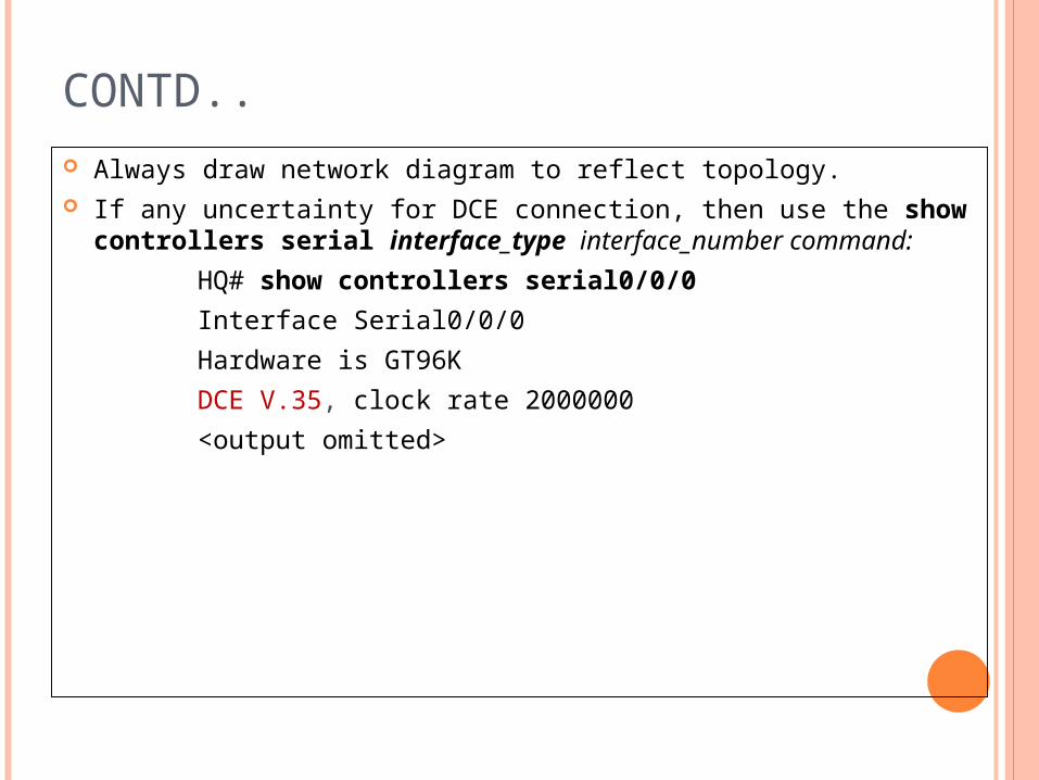
CONTD..
frame-relay route 102 interface Serial0/0/1 201
frame-relay route 103 interface Serial0/1/0 301 no shutdown!interface Serial0/0/1 description FR to East no ip address encapsulation frame-relay clock rate 64000 frame-relay lmi-type cisco frame-relay intf-type dce frame-relay route 201 interface Serial0/0/0 102 no shutdown!

CONTD…
interface Serial0/1/0
description FR to West
no ip address
encapsulation frame-relay
clock rate 64000
frame-relay lmi-type cisco
frame-relay intf-type dce
frame-relay route 301 interface Serial0/0/0 103
no shutdown
! End

STEP 3: CONFIGURING THE FRAME RELAY ENDPOINTS
Frame Relay(HQ), Spokes (East and West). Check the topology diagram for the data-link connection
identifiers (DLCIs). Off Turn Frame Relay Inverse Address Resolution Protocol
(InARP). Configure all Frame Relay interfaces as physical interfaces. Inverse ARP allows a Frame Relay network to discover the IP
address associated with the virtual circuit A desirable trait in a production network. Turn Inverse ARP off to limit the number of dynamic DLCIs
that are created.

CONTD…
Its work in these pahses;- For a global configuration mode enter the
configuration menu for that assign it an IP address with the help of ip address command.
fourth octet of the IP address is the router number (HQ=1, East=2, West=3
Assign the Frame Relay subnet to be 172.16.124.0 /29.
Enable Frame Relay encapsulation using the interface configuration command encapsulation frame-relay.
Disable Frame Relay Inverse ARP with the no frame-relay inverse-arp command.

CONTD….
Map the other IPs in the subnet to DLCIs, using the frame-relay map ip address dlci broadcast command
HQ# conf tHQ(config)# interface serial 0/0/1HQ(config-if)# ip address 172.16.124.1 255.255.255.248HQ(config-if)# encapsulation frame-relayHQ(config-if)# no frame-relay inverse-arpEast# conf tEast(config)# interface serial 0/0/1East(config-if)# ip address 172.16.124.2
255.255.255.248 East(config-if)# encapsulation frame-relayEast(config-if)# no frame-relay inverse-arp

CONTD..
East(config-if)# frame-relay map ip 172.16.124.1 201 broadcast
East(config-if)# frame-relay map ip 172.16.124.3 201 broadcast
East(config-if)# no shutdown
West# conft
West(config)# interface serial 0/0/0
West(config-if)# ip address 172.16.124.3 255.255.255.248
West(config-if)# no frame-relay inverse-arp
West(config-if)# encapsulation frame-relay
West(config-if)# frame-relay map ip 172.16.124.1 301 broadcast
West(config-if)# frame-relay map ip 172.16.124.2 301 broadcast
West(config-if)# clock rate 64000West(config-if)# no shutdown

CONTD.. Each frame relay end points check the
connectivity across the frame Relay network by the pinging the remote routers.
For more information about this behavior of Frame Relay, see the following FAQ page:
http://www.cisco.com/warp/public/116/fr_faq.pdf

STEP 4: SETTING INTERFACE-LEVEL BANDWIDTH
Set the Frame Relay serial interface bandwidth with the interface-level command bandwidth bandwidth, specifying the bandwidth in kilobits per second. For HQ, use 128 kbps. On East and West, use 64 kbps
by default, EIGRP limits its bandwidth usage to 50 percent of the value specified by the bandwidth parameter.
Each neighbor for which this is an outbound interface has a traffic limit of a fraction of that 50 percent, represented by 1/N, where N is the number of neighbors out that interface
HQ(config)# interface serial 0/0/1HQ(config-if)# bandwidth 128
East(config)# interface serial 0/0/1East(config-if)# bandwidth 64
West(config)# interface serial 0/0/0West(config-if)# bandwidth 64

CONTD…
How much bandwidth on Serial 0/0/1 on HQ is reserved for EIGRP traffic to East?
On HQ, up to 32 Kbps of bandwidth can be utilized for EIGRP traffic to East. This represents one fourth of the total bandwidth of that interface
Control both the bandwidth parameter and the EIGRP bandwidth percentage on a per-interface
On HQ, limit the bandwidth used by EIGRP to 40 percent without changing the bandwidth parameter on the interface.
The interface-level command ip bandwidth-percent eigrp as_number percent:
HQ(config-if)# ip bandwidth-percent eigrp 1 40
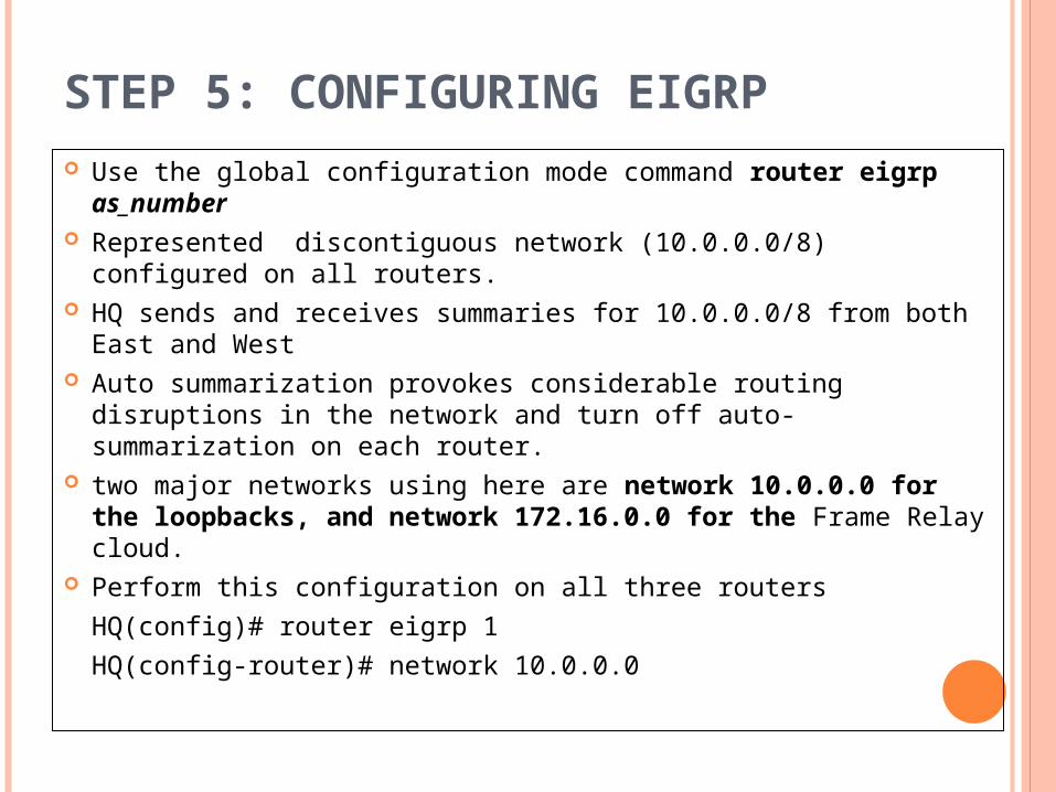
STEP 5: CONFIGURING EIGRP Use the global configuration mode command router eigrp
as_number Represented discontiguous network (10.0.0.0/8) configured on
all routers. HQ sends and receives summaries for 10.0.0.0/8 from both
East and West Auto summarization provokes considerable routing disruptions
in the network and turn off auto-summarization on each router. two major networks using here are network 10.0.0.0 for the
loopbacks, and network 172.16.0.0 for the Frame Relay cloud.
Perform this configuration on all three routers
HQ(config)# router eigrp 1
HQ(config-router)# network 10.0.0.0

CONTD..HQ(config-router)# network 172.16.0.0
HQ(config-router)# no auto-summary Same for East and West
Issue the show ip eigrp topology command on East:
East# show ip eigrp topology
IP-EIGRP Topology Table for AS(1)/ID(172.16.124.2)
Codes: P - Passive, A - Active, U - Update, Q - Query, R - Reply,
r - reply Status, s - sia Status
P 10.2.0.0/19, 1 successors, FD is 128256
via Connected, Loopback1
P 10.1.0.0/19, 1 successors, FD is 40640000
via 172.16.124.1 (40640000/128256), Serial0/0/1
P 10.2.32.0/19, 1 successors, FD is 128256
via Connected, Loopback33
P 10.1.32.0/19, 1 successors, FD is 40640000via 172.16.124.1 (40640000/128256), Serial0/0/1

CONTD…P 10.2.64.0/19, 1 successors, FD is 128256
via Connected, Loopback65P 10.1.64.0/19, 1 successors, FD is 40640000
via 172.16.124.1 (40640000/128256), Serial0/0/1P 10.2.96.0/19, 1 successors, FD is 128256
via Connected, Loopback97P 10.1.96.0/19, 1 successors, FD is 40640000
via 172.16.124.1 (40640000/128256), Serial0/0/1P 10.2.128.0/19, 1 successors, FD is 128256
via Connected, Loopback129P 10.1.128.0/19, 1 successors, FD is 40640000
via 172.16.124.1 (40640000/128256), Serial0/0/1P 10.2.160.0/19, 1 successors, FD is 128256
via Connected, Loopback161

CONTD..
P 10.1.160.0/19, 1 successors, FD is 40640000via 172.16.124.1 (40640000/128256),
Serial0/0/1P 172.16.124.0/29, 1 successors, FD is 40512000
via Connected, Serial0/0/1East#
Which networks are missing from the topology database?
All of the subnets in the 10.3.0.0/16 range are missing from East’s topology table. These are the remote loopback interfaces on the West router.
What do you suspect as being responsible for this problem?
This problem is caused by the split horizon functionality on R1. R1 will not send route updates from East to West because the incoming interface and outgoing interface are the same.
CONTD..
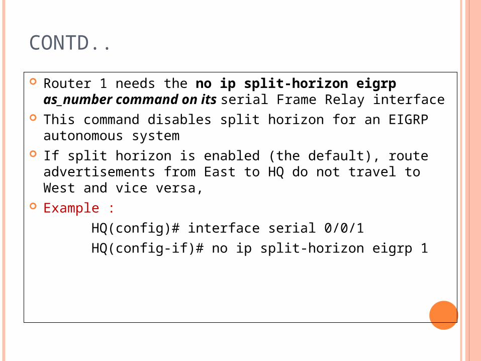
Router 1 needs the no ip split-horizon eigrp as_number command on its serial Frame Relay interface
This command disables split horizon for an EIGRP autonomous system
If split horizon is enabled (the default), route advertisements from East to HQ do not travel to West and vice versa,
Example :
HQ(config)# interface serial 0/0/1
HQ(config-if)# no ip split-horizon eigrp 1
CONTD..
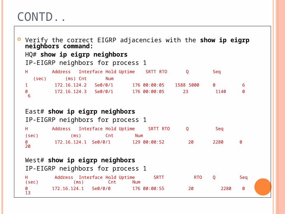
Verify the correct EIGRP adjacencies with the show ip eigrp neighbors command:
HQ# show ip eigrp neighborsIP-EIGRP neighbors for process 1
H Address Interface Hold Uptime SRTT RTO Q Seq
(sec) (ms) Cnt Num
1 172.16.124.2 Se0/0/1 176 00:00:05 1588 5000 0 6
0 172.16.124.3 Se0/0/1 176 00:00:05 23 1140 0 6
East# show ip eigrp neighborsIP-EIGRP neighbors for process 1
H Address Interface Hold Uptime SRTT RTO Q Seq
(sec) (ms) Cnt Num
0 172.16.124.1 Se0/0/1 129 00:00:52 20 2280 0 20
West# show ip eigrp neighborsIP-EIGRP neighbors for process 1
H Address Interface Hold Uptime SRTT RTO Q Seq (sec) (ms) Cnt Num
0 172.16.124.1 Se0/0/0 176 00:00:55 20 2280 0 13
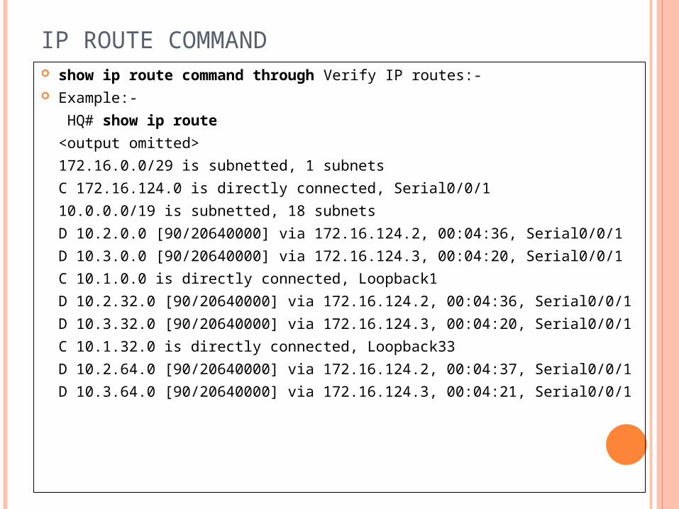
IP ROUTE COMMAND show ip route command through Verify IP routes:- Example:-
HQ# show ip route
<output omitted>
172.16.0.0/29 is subnetted, 1 subnets
C 172.16.124.0 is directly connected, Serial0/0/1
10.0.0.0/19 is subnetted, 18 subnets
D 10.2.0.0 [90/20640000] via 172.16.124.2, 00:04:36, Serial0/0/1
D 10.3.0.0 [90/20640000] via 172.16.124.3, 00:04:20, Serial0/0/1
C 10.1.0.0 is directly connected, Loopback1
D 10.2.32.0 [90/20640000] via 172.16.124.2, 00:04:36, Serial0/0/1
D 10.3.32.0 [90/20640000] via 172.16.124.3, 00:04:20, Serial0/0/1
C 10.1.32.0 is directly connected, Loopback33
D 10.2.64.0 [90/20640000] via 172.16.124.2, 00:04:37, Serial0/0/1
D 10.3.64.0 [90/20640000] via 172.16.124.3, 00:04:21, Serial0/0/1

CONTD..
C 10.1.64.0 is directly connected, Loopback65
D 10.2.96.0 [90/20640000] via 172.16.124.2, 00:04:37, Serial0/0/1
D 10.3.96.0 [90/20640000] via 172.16.124.3, 00:04:21, Serial0/0/1
C 10.1.96.0 is directly connected, Loopback97
D 10.2.128.0 [90/20640000] via 172.16.124.2, 00:04:37, Serial0/0/1
D 10.3.128.0 [90/20640000] via 172.16.124.3, 00:04:21, Serial0/0/1
C 10.1.128.0 is directly connected, Loopback129
D 10.2.160.0 [90/20640000] via 172.16.124.2, 00:04:37, Serial0/0/1
D 10.3.160.0 [90/20640000] via 172.16.124.3, 00:04:21, Serial0/0/1
C 10.1.160.0 is directly connected, Loopback161
Same as another Two (EAST and WEST) ip route.

TCL SCRIPTS
Run the following TCL script on all routers to verify full connectivity:
for each address {10.1.1.110.1.33.1 10.1.65.110.1.97.110.1.129.110.1.161.1172.16.124.110.2.1.110.2.33.110.2.65.110.2.97.110.2.129.110.2.161.1
(… continue)
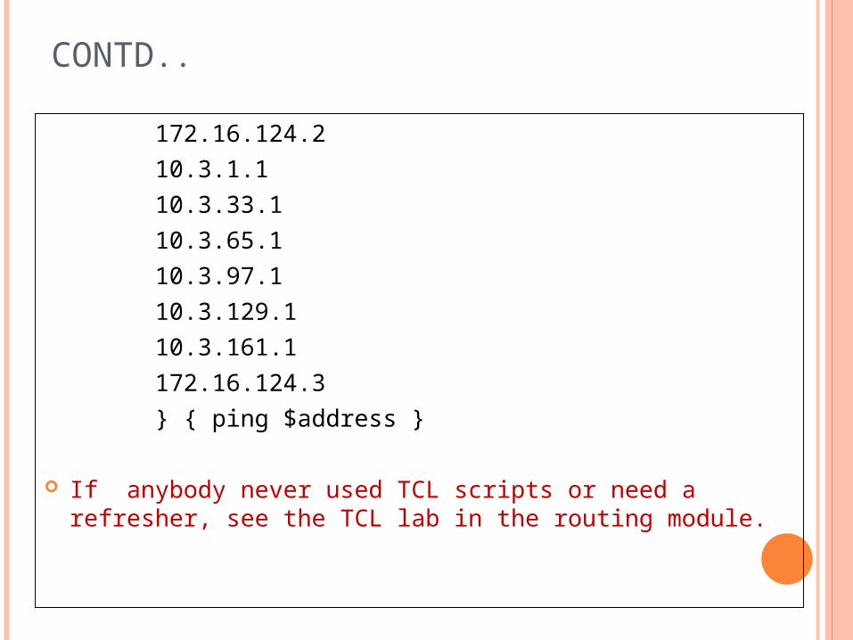
CONTD..
172.16.124.2
10.3.1.1
10.3.33.1
10.3.65.1
10.3.97.1
10.3.129.1
10.3.161.1
172.16.124.3
} { ping $address }
If anybody never used TCL scripts or need a refresher, see the TCL lab in the routing module.

STEP 6: USING NON-BROADCAST EIGRP MODE EIGRP use as default mode, which multicasts packets to the link-
local address 224.0.0.10 All Frame relay not support mulitcast. EIGRP supports unicasts to remote destinations using non
broadcast mode on a per-interface basis mode is analogous to configuring RIPv2 with a passive interface
and statically configuring neighbors out that interface To implement this functionality, do the following:
HQ(config)# router eigrp 1
HQ(config-router)# neighbor 172.16.124.2 serial 0/0/1
HQ(config-router)# neighbor 172.16.124.3 serial 0/0/1
East(config)# router eigrp 1
East(config-router)# neighbor 172.16.124.1 serial 0/0/1
West(config)# router eigrp 1
West(config-router)# neighbor 172.16.124.1 serial 0/0/0

CONTD…
HQ now has two neighbor statements, and the other two routers have one. Once you configure neighbor statements for a given interface, EIGRP automatically stops multicasting packets out that interface and starts unicasting packets instead. verify that all your changes have worked with the
show ip eigrp neighbors command:
HQ# show ip eigrp neighbors
IP-EIGRP neighbors for process 1
H Address Interface Hold Uptime SRTT RTO Q Seq
(sec) (ms) Cnt Num
1 172.16.124.2 Se0/0/1 153 00:00:28 65 390 0 9
0 172.16.124.3 Se0/0/1 158 00:00:28 1295 5000 0 9

IP EIGRP NEIGHBOURS
East# show ip eigrp neighbors
IP-EIGRP neighbors for process 1
H Address Interface Hold Uptime SRTT RTO Q Seq
(sec) (ms) Cnt Num
0 172.16.124.1 Se0/0/1 146 00:02:19 93 558 0 15
West# show ip eigrp neighbors IP-EIGRP neighbors for process 1
H Address Interface Hold Uptime SRTT RTO Q Seq
(sec) (ms) Cnt Num
0 172.16.124.1 Se0/0/0 160 00:03:00 59 354 0 15

STEP 7: IMPLEMENTING EIGRP MANUAL SUMMARIZATION
Implement EIGRP manual summarization on each of the routers. Each router should advertise only one network summarization.
What is the length of the network mask that is used to summarize all the loopbacks on each router?
Summarize all the loopbacks at the 24-bit boundary for each router. Simplified EIGRP topology table on each router using the show ip
eigrp topology command:
HQ# show ip eigrp topologyIP-EIGRP Topology Table for AS(1)/ID(10.1.12.1)Codes: P - Passive, A - Active, U - Update, Q - Query, R – Reply, r - reply Status, s - sia Status
P 10.2.0.0/16, 1 successors, FD is 2297856via 172.16.124.2 (2297856/128256), Serial0/0/1
P 10.3.0.0/16, 1 successors, FD is 2297856
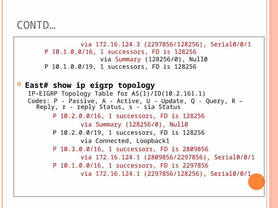
CONTD…
via 172.16.124.3 (2297856/128256), Serial0/0/1P 10.1.0.0/16, 1 successors, FD is 128256
via Summary (128256/0), Null0P 10.1.0.0/19, 1 successors, FD is 128256
East# show ip eigrp topologyIP-EIGRP Topology Table for AS(1)/ID(10.2.161.1)Codes: P - Passive, A - Active, U - Update, Q - Query, R – Reply, r - reply
Status, s - sia Status
P 10.2.0.0/16, 1 successors, FD is 128256via Summary (128256/0), Null0
P 10.2.0.0/19, 1 successors, FD is 128256via Connected, Loopback1
P 10.3.0.0/16, 1 successors, FD is 2809856via 172.16.124.1 (2809856/2297856), Serial0/0/1
P 10.1.0.0/16, 1 successors, FD is 2297856via 172.16.124.1 (2297856/128256), Serial0/0/1

WEST SHOW IP EIGRP TOPOLOGY
IP-EIGRP Topology Table for AS(1)/ID(172.16.124.3) Codes: P - Passive, A - Active, U - Update, Q - Query, R – Reply, r - reply
Status, s - sia Status
P 10.2.0.0/16, 1 successors, FD is 2809856
via 172.16.124.1 (2809856/2297856), Serial0/0/0
P 10.3.0.0/16, 1 successors, FD is 128256
via Summary (128256/0), Null0
P 10.3.0.0/19, 1 successors, FD is 128256
via Connected, Loopback1
P 10.1.0.0/16, 1 successors, FD is 2297856
via 172.16.124.1 (2297856/128256), Serial0/0/0
P 10.3.32.0/19, 1 successors, FD is 128256

APPENDIX A: TCL SCRIPT OUTPUT
HQ# tclshHQ(tcl)#foreach address {+>(tcl)#10.1.1.1+>(tcl)#10.1.33.1+>(tcl)#10.1.65.1+>(tcl)#10.1.97.1+>(tcl)#10.1.129.1+>(tcl)#10.1.161.1+>(tcl)#172.16.124.1+>(tcl)#10.2.1.1+>(tcl)#10.2.33.1+>(tcl)#10.2.65.1+>(tcl)#10.2.97.1+>(tcl)#10.2.129.1+>(tcl)#10.2.161.1+>(tcl)#172.16.124.2+>(tcl)#10.3.1.1+>(tcl)#10.3.33.1+>(tcl)#10.3.65.1

CONTD..+>(tcl)#10.3.97.1+>(tcl)#10.3.129.1+>(tcl)#10.3.161.1+>(tcl)#172.16.124.3+>(tcl)#} { ping $address }Type escape sequence to abort.
Sending 5, 100-byte ICMP Echos to 10.1.1.1, timeout is 2 seconds:!!!!!Success rate is 100 percent (5/5), round-trip min/avg/max = 1/1/1 msType escape sequence to abort. Sending 5, 100-byte ICMP Echos to 10.1.33.1, timeout is 2 seconds:!!!!!Success rate is 100 percent (5/5), round-trip min/avg/max = 1/1/4 msType escape sequence to abort.………………….………..….Success rate is 100 percent (5/5), round-trip min/avg/max = 40/42/44 ms
HQ(tcl)# tclquit

EAST TCL CODEEast# tclshEast(tcl)#foreach address {+>(tcl)#10.1.1.1+>(tcl)#10.1.33.1+>(tcl)#10.1.65.1+>(tcl)#10.1.97.1+>(tcl)#10.1.129.1+>(tcl)#10.1.161.1+>(tcl)#172.16.124.1+>(tcl)#10.2.1.1+>(tcl)#10.2.33.1+>(tcl)#10.2.65.1+>(tcl)#10.2.97.1+>(tcl)#10.2.129.1+>(tcl)#10.2.161.1+>(tcl)#172.16.124.2

CONTD..
+>(tcl)#10.3.1.1+>(tcl)#10.3.33.1+>(tcl)#10.3.65.1+>(tcl)#10.3.97.1+>(tcl)#10.3.129.1+>(tcl)#10.3.161.1+>(tcl)#172.16.124.3+>(tcl)#} { ping $address }
Type escape sequence to abort.Sending 5, 100-byte ICMP Echos to 10.1.1.1, timeout is 2 seconds:!!!!!Success rate is 100 percent (5/5), round-trip min/avg/max =
40/42/44 msType escape sequence to abort.Sending 5, 100-byte ICMP Echos to 10.1.33.1, timeout is 2 seconds:!!!!!................………………………….Success rate is 100 percent (5/5), round-trip min/avg/max =
84/84/88 msEast(tcl)# tclquit

CONTD…West# tclshWest(tcl)#foreach address {+>(tcl)#10.1.1.1+>(tcl)#10.1.33.1+>(tcl)#10.1.65.1+>(tcl)#10.1.97.1+>(tcl)#10.1.129.1+>(tcl)#10.1.161.1+>(tcl)#172.16.124.1+>(tcl)#10.2.1.1+>(tcl)#10.2.33.1+>(tcl)#10.2.65.1+>(tcl)#10.2.97.1+>(tcl)#10.2.129.1+>(tcl)#10.2.161.1+>(tcl)#172.16.124.2+>(tcl)#10.3.1.1

+>(tcl)#10.3.33.1+>(tcl)#10.3.65.1+>(tcl)#10.3.97.1+>(tcl)#10.3.129.1+>(tcl)#10.3.161.1+>(tcl)#172.16.124.3+>(tcl)#} { ping $address }Type escape sequence to abort.Sending 5, 100-byte ICMP Echos to 10.1.1.1, timeout is 2 seconds:!!!!!Success rate is 100 percent (5/5), round-trip min/avg/max =
40/42/44 msType escape sequence to abort.Sending 5, 100-byte ICMP Echos to 10.1.33.1, timeout is 2 seconds:!!!!!………………….………….Success rate is 100 percent (5/5), round-trip min/avg/max =
84/84/84 msWest(tcl)# tclquit
CONTD…

END OF LAB CONFIGS:HQ#show runBuilding configuration...!hostname HQ!interface Loopback1ip address 10.1.1.1 255.255.224.0!interface Loopback33ip address 10.1.33.1 255.255.224.0!interface Loopback65ip address 10.1.65.1 255.255.224.0!interface Loopback97ip address 10.1.97.1 255.255.224.0!interface Loopback129ip address 10.1.129.1 255.255.224.0!

CONTD..interface Loopback161ip address 10.1.161.1 255.255.224.0!interface Serial0/0/1ip address 172.16.124.1 255.255.255.248encapsulation frame-relayno ip split-horizon eigrp 1ip summary-address eigrp 1 10.1.0.0 255.255.0.0 5frame-relay map ip 172.16.124.1 102frame-relay map ip 172.16.124.2 102 broadcastframe-relay map ip 172.16.124.3 103 broadcastno frame-relay inverse-arpno shutdown!router eigrp 1network 10.0.0.0network 172.16.0.0no auto-summaryneighbor 172.16.124.3 Serial0/0/1neighbor 172.16.124.2 Serial0/0/1!end

EAST SHOW RUNEast#show runBuilding configuration...!hostname East!interface Loopback1ip address 10.2.1.1 255.255.224.0!interface Loopback33ip address 10.2.33.1 255.255.224.0!interface Loopback65ip address 10.2.65.1 255.255.224.0!interface Loopback97ip address 10.2.97.1 255.255.224.0!interface Loopback129ip address 10.2.129.1 255.255.224.0!interface Loopback161ip address 10.2.161.1 255.255.224.0!

CONTD..interface Serial0/0/1
ip address 172.16.124.2 255.255.255.248
encapsulation frame-relay
ip summary-address eigrp 1 10.2.0.0 255.255.0.0 5
frame-relay map ip 172.16.124.1 201 broadcast
frame-relay map ip 172.16.124.2 201
frame-relay map ip 172.16.124.3 201 broadcast
no frame-relay inverse-arp
no shutdown
!
router eigrp 1
network 10.0.0.0
network 172.16.0.0
no auto-summary
neighbor 172.16.124.1 Serial0/0/1
!
end

WEST SHOW RUNWest#show runBuilding configuration...!hostname West!interface Loopback1ip address 10.3.1.1 255.255.224.0!interface Loopback33ip address 10.3.33.1 255.255.224.0!interface Loopback65ip address 10.3.65.1 255.255.224.0!interface Loopback97ip address 10.3.97.1 255.255.224.0!interface Loopback129ip address 10.3.129.1 255.255.224.0!interface Loopback161ip address 10.3.161.1 255.255.224.0!

CONTD..interface Serial0/0/0
ip address 172.16.124.3 255.255.255.248
encapsulation frame-relay
ip summary-address eigrp 1 10.3.0.0 255.255.0.0 5
frame-relay map ip 172.16.124.1 301 broadcast
frame-relay map ip 172.16.124.2 301 broadcast
frame-relay map ip 172.16.124.3 301
no frame-relay inverse-arp
frame-relay lmi-type cisco
no shutdown
!
router eigrp 1
network 10.0.0.0
network 172.16.0.0
no auto-summary
neighbor 172.16.124.1 Serial0/0/0
!
end

Thank You