Embed Size (px)
Citation preview
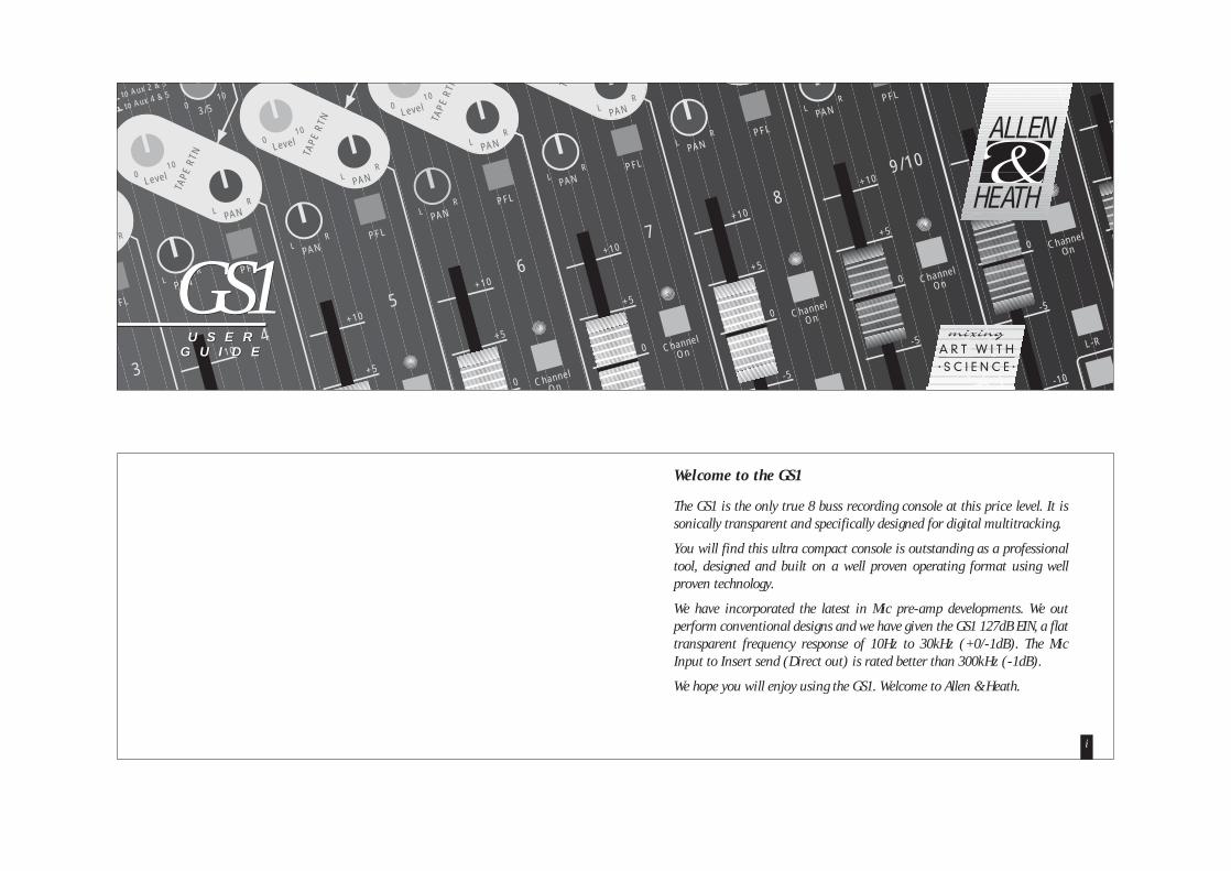
The GS1 is the only true 8 buss recording console at this price level. It issonically transparent and specifically designed for digital multitracking.
You will find this ultra compact console is outstanding as a professionaltool, designed and built on a well proven operating format using wellproven technology.
We have incorporated the latest in Mic pre-amp developments. We outperform conventional designs and we have given the GS1 127dB EIN, a flattransparent frequency response of 10Hz to 30kHz (+0/-1dB). The MicInput to Insert send (Direct out) is rated better than 300kHz (-1dB).
We hope you will enjoy using the GS1. Welcome to Allen & Heath.
Welcome to the GS1
i
3/5010to Aux 2 & 3
to Aux 4 & 5
Level010
Level010
Level010
L
TAPE
RTN TA
PE R
TN TAPE
RTN TA
R
PANLR
PANLR
PANLR
PANLR
PFL
PFL
PANLR
PFL
PANLR
PFL
PANLR
PFL
PANLR
PFL
PANLR
PFL
PANLR
A
3
4
5
6
7
Channel
On
8
Channel
On
9/10
Channel
On
11/12
+10
+5
+10
0
+5
+10
0
+5
+10
-5
0
+5
+10
-5
0
+5
+10
-10
-5
0
+5
+10
Channel
On
Channel
On
L-R
L-R
2
GS1U S E R
G U I D E
GS1U S E R
G U I D E
Section 1 GETTING STARTEDBlock DiagramConnectionsSection 2 SIGNAL PATHSMono Input and Stereo Input PathsEQAuxMonitor and Stereo ReturnsPFL, Pan, Channel On and RoutingMeters and the Master SectionSection 3 USING MUTE AUTOMATIONMute PatchesConnectionsUses for Automation
Section 4 MIDI APPLICATIONSMIDI Transport Control (MMC)MIDI CommandsSection 5 GETTING THE BEST FROM THE GS1Level MatchingEarthing Grouping and PatchbaysSection 6 SPECIFICATIONS AND OPTIONSGS1 and ExpanderMeterbridge and PSUConnector Diagrams - Jacks, Phono’s & XLR’sMIDI ImplementationAudio Specifications
CONTENTS GS1
iii
PAGE PAGE13
579
111315
171921
2325
272932
3334353738
This product has been manufactured in the UK by Allen &Heath Ltd and is warranted from defects in materials orworkmanship for a period of one year from the date ofpurchase by the original owner.To ensure the high level of performance and reliabilityfor which this equipment has been designed and man-ufactured, please read this User Guide before use.In the event of failure notify and return the defective unit toALLEN & HEATH or its authorised agent as soon as possiblefor repair under warranty subject to the following conditions:
1
2
3
4
5
The equipment has been installed and operated in accor-dance with this User Guide.The equipment has not been subject to misuse eitherintended or accidental, neglect, or alteration other thandescribed in this User Guide or the Service Manual, orapproved by ALLEN & HEATH.Any necessary adjustment, alteration, or repair has beenmade by ALLEN & HEATH or its authorised agent.The defective unit is to be returned, carriage prepaid, toALLEN & HEATH or its authorised agent and proof ofpurchase made available on request.Units to be returned should be packed to avoid transitdamage and be accompanied by the Power Supply Unit.These terms of warranty apply to UK sales. In other territo-ries the terms may vary according to legal requirements.
Copyright © 1995 Allen & Heath LimitedAll rights reserved
Publication AP2061 Issue 2
Information in this manual is subject to change without notice anddoes not represent a commitment on the part of the vendor.Allen & Heath Limited shall not be liable for any loss or damage what-soever arising from the use of information or error contained in thismanual.
No part of this manual may be reproduced in any form without priorpermission from Allen & Heath Limited.
Allen & Heath LimitedKernick Industrial Estate, Penryn, Cornwall, England TR10 9LU.Tel : (44) 01326 372 070. Fax : (44) 01326 377 097
CONDITIONS OF WARRANTYLIMITED ONE YEAR WARRANTY
ii
MICROPHONEPHANTOM POWER
MIC/LINE XLR2= +
LINE IN LINE/XL
MI
H
M
L
3 BAND EQUALISER
INSERT TIP -
RING - MIXDOWN
TAPE RTN IN
GAIN
LEVEL
2/4
3/5
1
PF
FADER
CHANNELON
MUTEPROCESSOR
1-2
3-4
5-6
7-8
L-R
AUX
1-GR
P 1-
LEF
RIGH
TPF
AUX 1 PRE
AUX 1 POST
AUX 2
AUX 4
AUX 5
AUX 3
MONO INPUT 1 OF 8
PAN
PAN
1-2
3-4
5-6
7-8
L-R
PAN
CHANNELON
MUTEPROCESSOR
2/4
3/5
1
AUX 1 PRE
AUX 1 POST
AUX 2
AUX 4
AUX 5
AUX 3
HF
2 BAND EQUALISER
LF
FADER
L
HIGAIN
L/MONO
R
STEREOINPUTS
PANLEVEL
L/MONO
R
STEREORETURNS
EXPANDER
STEREO INPUT 1 OF 4
PF AUX
1-GR
P 1-
LEF
RIGH
TPF
AUX
1-5
GR
P 1-
8
LEFT
RIG
HT
PFL
GROUP (1-8) MIX
EXPANDER METERBRIDGE
GROUP (1-8) OUT GROUP1 OF 8
LEVEL
TIP = +
AUX 2-51 OF 4
AUX (2-5) OUT
AUX 1AUX 1 PRE MIX
AUX 1 POST MIX TIP = +
AUX 1 OUT
AUX (POST)
LEVEL
AUX (2-5) MIX
L INSERTLEFT MIX
R INSERTRIGHT MIX
L
2 TRACK OUT(MAIN OUT)
R
FADER
2 TRACK INAUX1
L-R
2TRK
PFL MIX
PFL DCPFL
ACTIVE
MONITORLEVEL
CUE TOHEADPHONES
MONITOROUTPUT
MUTE
HEADPHONESL
R
L
R
MONITOR AMP& SPEAKERS
L
LEVELMATCH
LO
HI
R MONITOR METER
MONITOR
MASTER
CUE (PRE)
MUTE PROCESSOR
MIDIIN
DPTO-ISOLATOR
MIDITHRU
MIDIOUT
MODE
LEARN
SET LOC
FF >>
REW <<
PLAY >
LOCATE
F6
F5
F4
F3
F2
F1
MUTEPROCESSOR
STOP
MMCPATCHMIDILEARN
EXPANDER
CHANNEL ONSWITCHESMMC FUNCTION KEYS
CHANNEL ONMUTES AND LEDS
PSU
AC 36VPOWER INPUT
ONLY USE ADAPTOR PROVIDED
POWER
1
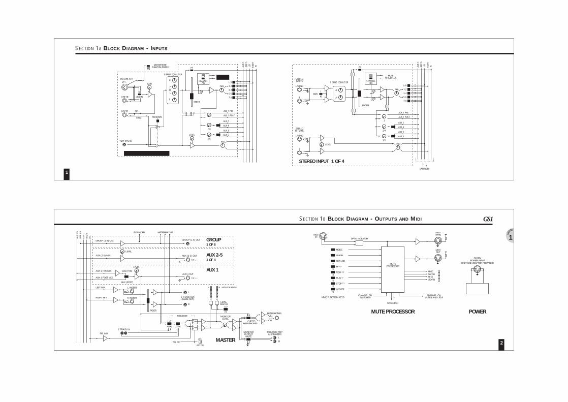
SECTION 1B BLOCK DIAGRAM - OUTPUTS AND MIDI
2
GS1
1
SECTION 1A BLOCK DIAGRAM - INPUTS
1123456789
10111213
NOTES Group outputs to Recorder.Tape returns from Recorder.Microphone inputs.Line inputs from line devices.Input stage inserts for gates, compressors and expanders etc.Stereo line inputs from line devices.Stereo Returns for FX devices.Aux sends 2 to 5 to FX devices.Aux 1 to cue amp and headphone mix.L R inserts for compressors or EQ etc.Engineer’s headphone monitor.L R monitor O/P to monitor speaker amp and speakers.L R mix to and from 2 track master recorder.
CONNECTIONS
4
GS1
3
SECTION 1 GETTING STARTED
'MIXdown'
Line Insert
1Mic
Microphone
XLR / Line
1 GROUPout
TAPE RTNin
1 GROUPout
Line Insert
2Mic
Microphone
2 GROUPout
TAPE RTNin
GROUPout
Microphone
3 GROUPout
TAPE RTNin
GROUPout
Line Insert
3Mic
Microphone
4 GROUPout
TAPE RTNin
GROUPout
Line Insert
4Mic
Microphone
5 GROUPout
TAPE RTNin
GROUPout
Line Insert
5Mic
Microphone
6 GROUPout
TAPE RTNin
GROUPout
Line Insert
6Mic
Microphone
7 GROUPout
TAPE RTNin
GROUPout
Line Insert
7Mic
Line Insert
8Mic
Microphone
8 GROUPout
TAPE RTNin
GROUPout
Mic
roph
one
Pha
ntom
Pow
er
1
9/10
L/Mono RStereo Inputs
11/12
L/Mono RStereo Inputs
13/14
L/Mono RStereo Inputs
15/16
L/Mono RStereo Inputs
L/Mono RStereo Returns
L/Mono RStereo Returns
L/Mono RStereo Returns
2AUXILIARY
out
27/28 29/30 31/3225/26
53 Headphones
4L/Mono RStereo Returns
LINSERT
R
SEND (tip)
RETURN (ring)
+6+6
MIDIout
MIDIthru'
MIDIin
AC 36VPower Input
Only use adaptor provided
Serial No.
Made in England by Allen & Heath Ltd
2 TRACKin
L R 2 TRACKout
(Main out)
L R Mon. Amp& Speakers
L R
L R
Mic - XLRXLR pad orLine Jack
XLR / Line
XLR / Line
XLR / Line
XLR / Line
XLR / Line
XLR / Line
XLR / Line
STEREO INPUT SECTION
31 2
31 2
31 2
31 2
31 2
31 2
31 2
31 2
CUE AMP
R
COMPRESSOR,GRAPHICS ETC.
L
SAMPLERKEYBOARD
8 TRACK RECORDER
8 8
DAT22
8
VOICE
GATES, COMPRESSORS, EXPANDERS
DRUMMACHINE
7
321
STUDIO FX2
STUDIO FX1
STUDIO DELAY
STUDIO DELAY8
6
12
9
STUDIO AMP
10
115
4
13
1
2
3
4
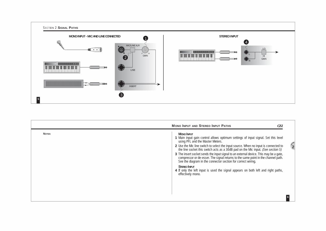
MONO INPUTMain input gain control allows optimum settings of input signal. Set this levelusing PFL and the Master Meters.Use the Mic line switch to select the input source. When no input is connected tothe line socket this switch acts as a 30dB pad on the Mic input. (See section 5)The insert socket sends the input signal to an external device. This may be a gate,compressor or de-esser. The signal returns to the same point in the channel path.See the diagram in the connector section for correct wiring.
STEREO INPUTIf only the left input is used the signal appears on both left and right paths,effectively mono.
MONO INPUT AND STEREO INPUT PATHS
6
2
GS1
NOTES
STEREO INPUT
L
R
MONO INPUT - MIC AND LINE CONNECTED
4
GAIN
1
MIC/LINE XLR
2
31 2
GAIN
LINE
INSERT
3
LO
HI0 10
5
SECTION 2 SIGNAL PATHS
1
2
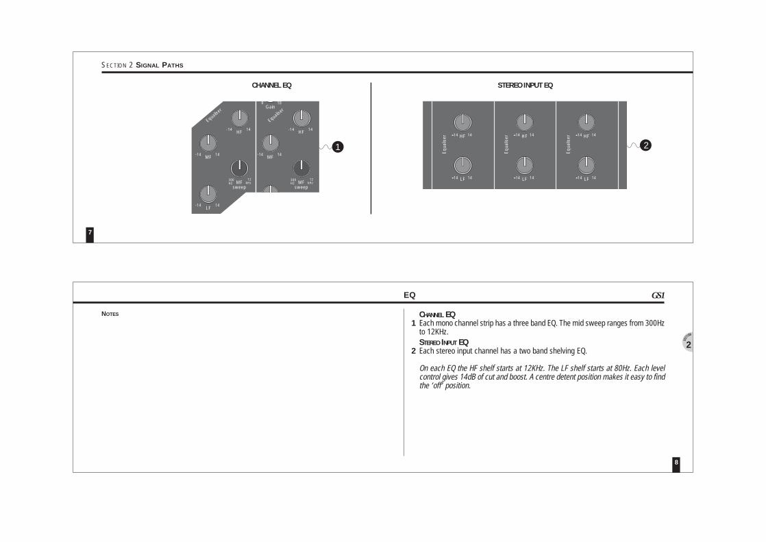
CHANNEL EQEach mono channel strip has a three band EQ. The mid sweep ranges from 300Hzto 12KHz.STEREO INPUT EQEach stereo input channel has a two band shelving EQ.
On each EQ the HF shelf starts at 12KHz. The LF shelf starts at 80Hz. Each levelcontrol gives 14dB of cut and boost. A centre detent position makes it easy to findthe ‘off’ position.
EQ
8
2
GS1
NOTES
HF 14
LF 14
Equ
alis
er HF 14
LF 14
Equ
alis
er HF 14
LF 14
Equ
alis
er-14
-14
-14
-14
-14
-14
21
Equalise
r
M Xdow
LF-14 14
MFsweep
300HZ
12kHz
MF
Gain
HF
-14 14
-14 14
0 10Gain
0 10
LF-14 14
MFsweep
300HZ
12kHz
MF-14 14
Equalise
r
M Xdow
HF-14 14
CHANNEL EQ STEREO INPUT EQ
7
SECTION 2 SIGNAL PATHS
1
2
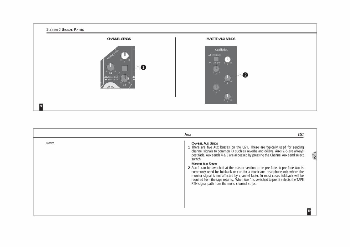
CHANNEL AUX SENDSThere are five Aux busses on the GS1. These are typically used for sendingchannel signals to common FX such as reverbs and delays. Auxs 2-5 are alwayspost fade. Aux sends 4 & 5 are accessed by pressing the Channel Aux send selectswitch.MASTER AUX SENDSAux 1 can be switched at the master section to be pre fade. A pre fade Aux iscommonly used for foldback or cue for a musicians headphone mix where themonitor signal is not affected by channel fader. In most cases foldback will berequired from the tape returns, When Aux 1 is switched to pre, it selects the TAPERTN signal path from the mono channel strips.
AUX
10
2
GS1
NOTES
CHANNEL SENDS MASTER AUX SENDS
AUX (post)
CUE (pre)1
2
3
4
5
Auxiliaries
0 10
0 10
0 10
0 10
0 10
0
01
LF-14 14
0 10
-14
Auxilia
ry Sen
ds
0 10 0
3/50 10
to Aux 2 & 3to Aux 4 & 5
2/4
1
2
9
SECTION 2 SIGNAL PATHS
21
2
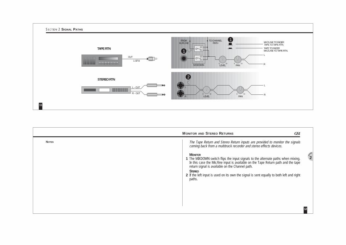
NOTES The Tape Return and Stereo Return inputs are provided to monitor the signalscoming back from a multitrack recorder and stereo effects devices.
MONITORThe MIXDOWN switch flips the input signals to the alternate paths when mixing.In this case the Mic/line input is available on the Tape Return path and the tapereturn signal is available on the Channel path.STEREOIf the left input is used on its own the signal is sent equally to both left and rightpaths.
MONITOR AND STEREO RETURNS
12
GS1
STEREO RTN
L
RLEVEL PANMIXDOWN
L
RPAN
L
R
2
FROMXLR/LINE
TO CHANNELPATH
0 10 0 10
LEVEL0 10 0 10
L - OUT
R - OUT
1
MIC/LINE TO FADERTAPE TO TAPE RTN.TAPE TO FADERMIC/LINE TO TAPE RTN.
1
1 OF 8
TAPE RTN
OUT
11
SECTION 2 SIGNAL PATHS
1
2
3
4
5
6
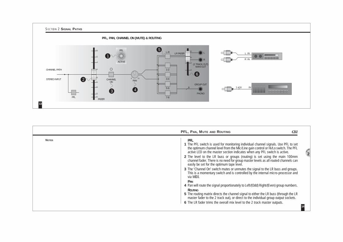
PFLThe PFL switch is used for monitoring individual channel signals. Use PFL to setthe optimum channel level from the Mic/Line gain control or Hi/Lo switch. The PFLactive LED on the master section indicates when any PFL switch is active.The level to the LR buss or groups (routing) is set using the main 100mmchannel fader. There is no need for group master levels as all routed channels caneasily be set for the optimum tape level.The ‘Channel On’ switch mutes or unmutes the signal to the LR buss and groups.This is a momentary switch and is controlled by the internal micro-processor andvia MIDI.PANPan will route the signal proportionately to Left/(Odd) Right/(Even) group numbers.ROUTINGThe routing matrix directs the channel signal to either the LR buss (through the LRmaster fader to the 2 track out), or direct to the individual group output sockets.The LR fader trims the overall mix level to the 2 track master outputs.
PFL, PAN, MUTE AND ROUTING
14
2
GS1
NOTES
PANCHANNELON
PFL
CHANNEL PATH
STEREO INPUT
(2 TRACK OUT)MAIN OUT
GROUP OUT
LR FADERPFL
ACTIVE
8
FADER
1-2
3-4
5-6
7-8
1
2
3
PFL, PAN, CHANNEL ON (MUTE) & ROUTING
0 10
¥
-30
-20
-15
-10
-5
0
+5
+10
-5
0
+5
+10
4
L-R5
6
PHONO
L IN
R IN
1 of 8
L
R
IN
13
SECTION 2 SIGNAL PATHS
1
2
3
4
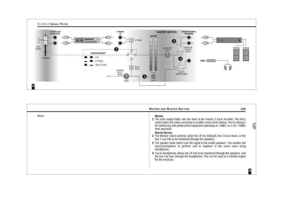
METERSThe main output fader sets the level to the master 2 track recorder. The Hi/Loswitch alters the meter sensitivity to enable correct level setting. The Hi setting isfor interfacing with professional equipment operating at +4dBu. Lo is for -10dBulevel operation.MASTER SECTIONThe Monitor Select switches allow the LR mix (Default), the 2 track return, or theAux 1 cue mix to be monitored through the speakers.The speaker mute switch cuts the signal to the studio speakers. This enables themusician/engineer to perform and to engineer in the same room usingHeadphones.Cue to headphones allows the LR mix to be monitored through the speakers, andthe Aux Cue buss through the headphones. This can be used as a monitor outputfor the musician.
METERS AND MASTER SECTION
16
2
GS1
NOTES
LR FADER
MONITORLEVEL
MONITOROUTPUTMUTU
CUE TOHEADPHONES
L
R
MIXBUSS
L
R
MONITOR AMP &SPEAKERS
3
4
-5
0
+5
+10
MASTER SECTION2 TRACK OUT(MAIN OUT)
MONITOR SELECT
AUX 1(CUE)
2 TRACK
LEVEL
MASTERAUX 1BUSS
2 TRACKIN
= LR
= 2 TRACK
= AUX 1 (CUE)
2
HI/LO
1
METERS
15
SECTION 2 SIGNAL PATHS
1234
5
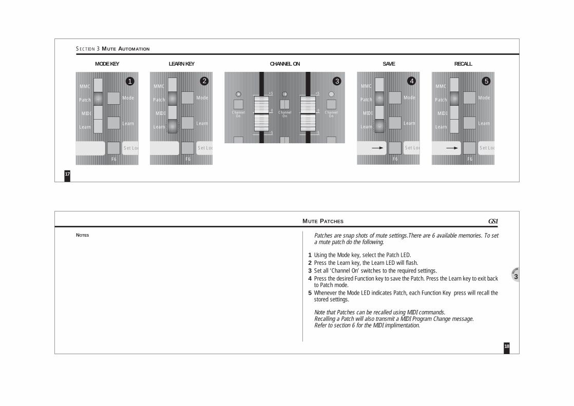
Patches are snap shots of mute settings.There are 6 available memories. To seta mute patch do the following.
Using the Mode key, select the Patch LED.Press the Learn key, the Learn LED will flash.Set all ‘Channel On’ switches to the required settings.Press the desired Function key to save the Patch. Press the Learn key to exit backto Patch mode.Whenever the Mode LED indicates Patch, each Function Key press will recall thestored settings.
Note that Patches can be recalled using MIDI commands.Recalling a Patch will also transmit a MIDI Program Change message.Refer to section 6 for the MIDI implimentation.
MUTE PATCHES
18
3
GS1
NOTES
ChannelOn
-5
0
+5
annelOn
-5
0
+5
ChannelOn
ChanO
3
MODE KEY
Mode
Learn
Set Loc
F6
MMC
Patch
MIDI
Learn
5
LEARN KEY CHANNEL ON SAVE RECALL
Mode
Learn
Set Loc
F6
MMC
Patch
MIDI
Learn
1
Mode
Learn
Set Loc
F6
MMC
Patch
MIDI
Learn
Mode
Learn
Set Loc
F6
MMC
Patch
MIDI
Learn
2 4
17
SECTION 3 MUTE AUTOMATION
12
3
123
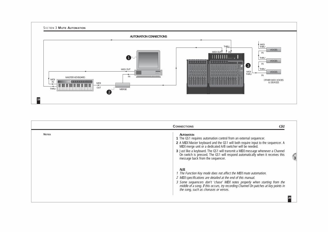
AUTOMATIONThe GS1 requires automation control from an external sequencer.A MIDI Master keyboard and the GS1 will both require input to the sequencer. AMIDI merge unit or a dedicated A/B switcher will be needed.Just like a keyboard. The GS1 will transmit a MIDI message whenever a ChannelOn switch is pressed. The GS1 will respond automatically when it receives thismessage back from the sequencer.
N.B.The Function Key mode does not affect the MIDI mute automation.MIDI specifications are detailed at the end of this manual.Some sequencers don’t ‘chase’ MIDI notes properly when starting from themiddle of a song. If this occurs, try recording Channel On patches at key points inthe song, such as choruses or verses.
CONNECTIONS
20
3
GS1
NOTES
THRU OUT
MASTER KEYBOARD
31 2
31 2
31 2
31 2
31 2
31 2
31 2
31 2
GS1
31 2
31 2
31 2
31 2
31 2
31 2
31 2
31 2
GS1Compact Studio Consolemeterbridge
VOICES
VOICES
VOICES
THRU
THRU
IN
THRU
IN
IN
OTHER MIDI VOICES& DEVICES
3
AUTOMATION CONNECTIONS
MIDI
MIDI
MIDITHRU
MIDIIN
MIDI OUT IN
THRU
1
2
OUTMIDI
IN
MERGE
19
SECTION 3 MUTE AUTOMATION
1
2
3
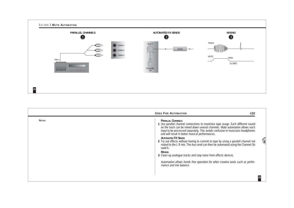
PARALLEL CHANNELSUse parallel channel connections to maximise tape usage. Each different soundon the track can be mixed down several channels. Mute automation allows eachinput to be processed separately. This avoids confusion in musicians headphonesand will result in better musical performances.AUTOMATED FX SENDSTry out effects without having to commit to tape by using a paralell channel notrouted to the L R mix. The Aux send can then be automated using the Channel Onswitch.MIXINGClean up analogue tracks and stop noise from effects devices.
Automation allows hands free operation for other creative tasks such as perfor-mance and mix balance.
USES FOR AUTOMATION
22
3
GS1
NOTES
CHAN 1
CHAN 2
CHAN 3
1 2
ECHO
AUX 2 TRACK
OPEN
CLOSED
3
0 10
PARALLEL CHANNELS AUTOMATED FX SENDS MIXING
CHANNELON
MUTETRK 4
21
SECTION 3 MUTE AUTOMATION
1
2
3
4
5
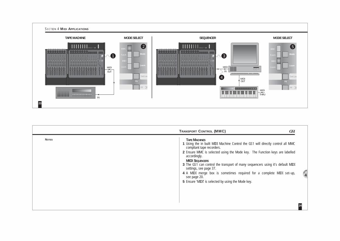
TAPE MACHINESUsing the in built MIDI Machine Control the GS1 will directly control all MMCcompliant tape recorders.Ensure MMC is selected using the Mode key. The Function keys are labelledaccordingly.MIDI SEQUENCERSThe GS1 can control the transport of many sequencers using it’s default MIDIsettings, see page 37.A MIDI merge box is sometimes required for a complete MIDI set-up,see page 20.Ensure ‘MIDI’ is selected by using the Mode key.
TRANSPORT CONTROL (MMC)
24
4
GS1
NOTES
Mode
Learn
Set Loc
FF
F6
2
Mode
Learn
MMC
Set Loc
FF
F6
F5
Patch
MIDI
Learn
IN
31 2
31 2
31 2
31 2
31 2
31 2
31 2
31 2
GS1
31 2
31 2
31 2
31 2
31 2
31 2
31 2
31 2
GS1Compact Studio Consolemeterbridge
1
MIDIOUT
31 2
31 2
31 2
31 2
31 2
31 2
31 2
31 2
GS1
31 2
31 2
31 2
31 2
31 2
31 2
31 2
31 2
GS1Compact Studio Consolemeterbridge
3
4
TAPE MACHINE MODE SELECT SEQUENCER MODE SELECT
IN
MIDI
OUT
MIDI
Mode
Learn
Set Loc
FF
F6
5
Mode
Learn
MMC
Set Loc
FF
F6
F5
Patch
MIDI
Learn
THRU
MIDI
23
SECTION 4 MIDI APPLICATIONS
1
2
3
45
6
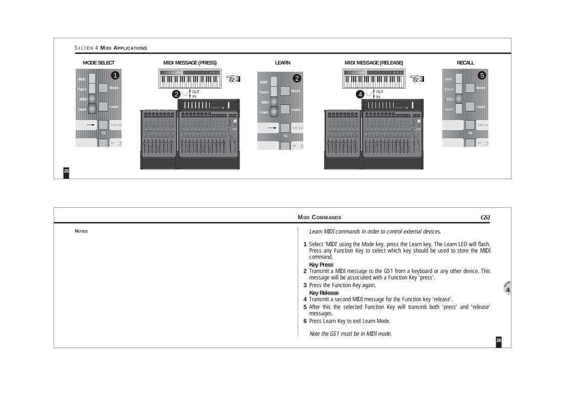
Learn MIDI commands in order to control external devices.
Select ‘MIDI’ using the Mode key, press the Learn key. The Learn LED will flash.Press any Function Key to select which key should be used to store the MIDIcommand.Key PressTransmit a MIDI message to the GS1 from a keyboard or any other device. Thismessage will be associated with a Function Key ‘press’.Press the Function Key again.Key ReleaseTransmit a second MIDI message for the Function key ‘release’.After this the selected Function Key will transmit both ‘press’ and ‘release’messages.Press Learn Key to exit Learn Mode.
Note the GS1 must be in MIDI mode.
MIDI COMMANDS
26
4
GS1
NOTES
OUTIN
31 2
31 2
31 2
31 2
31 2
31 2
31 2
31 2
GS1
31 2
31 2
31 2
31 2
31 2
31 2
31 2
31 2
GS1Compact Studio Consolemeterbridge
2 OUTIN
31 2
31 2
31 2
31 2
31 2
31 2
31 2
31 2
GS1
31 2
31 2
31 2
31 2
31 2
31 2
31 2
31 2
GS1Compact Studio Consolemeterbridge
4
MODE SELECT MIDI MESSAGE (PRESS) LEARN MIDI MESSAGE (RELEASE) RECALL
Mode
Learn
Set Loc
FF
F6
51
Mode
Learn
MMC
Set Loc
FF
F6
F5
Patch
MIDI
Learn
Mode
Learn
MMC
Set Loc
FF
F6
F5
Patch
MIDI
Learn
Mode
Learn
MMC
Set Loc
FF
F6
F5
Patch
MIDI
Learn
2
Mode
Learn
MMC
Set Loc
FF
F6
F5
Patch
MIDI
Learn
Mode
Learn
MMC
Set Loc
FF
F6
F5
Patch
MIDI
Learn
25
SECTION 4 MIDI APPLICATIONS
1
2
34567
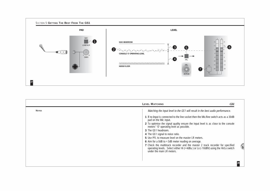
Matching the input level to the GS1 will result in the best audio performance.
If no Input is connected to the line socket then the Mic/line switch acts as a 30dBpad on the Mic input.To optimise the signal quality ensure the input level is as close to the consolemeters’ ‘O’ operating level as possible.The GS1 headroom.The GS1 signal to noise ratio.Use PFL to measure level on the master LR meters.Aim for a 0dB to +3dB meter reading on average.Check the multitrack recorder and the master 2 track recorder for specifiedoperating levels. Select either Hi (+4dBu ) or Lo (-10dBV) using the Hi/Lo switchunder the main LR meters.
LEVEL MATCHING
28
5
GS1
NOTES
3
GAIN
LINE/XLR
MIC
5
PFL
1
PAD
0 10
+6+6
+3+3
00
-3-3
-6-6
-10-10
-15-15
-20-20
L R
Hi
LoPFL
ACTIVE
LEVEL
MAX HEADROOM
NOISE FLOOR
6
4
2CONSOLE 'O' OPERATING LEVEL
7
27
SECTION 5 GETTING THE BEST FROM THE GS1
31 2
31 2
31 2
31 2
31 2
31 2
31 2
31 2
GS1
31 2
31 2
31 2
31 2
31 2
31 2
31 2
31 2
GS1Compact Studio Consolemeterbridge
STARPOINTEARTH
29
SECTION 5 GETTING THE BEST FROM THE GS1
1
2
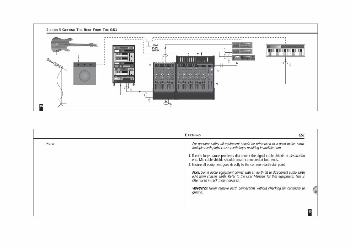
For operator safety all equipment should be referenced to a good mains earth.Multiple earth paths cause earth loops resulting in audible hum.
If earth loops cause problems disconnect the signal cable shields at destinationend. Mic cable shields should remain connected at both ends.Ensure all equipment goes directly to the common earth star point.
Note: Some audio equipment comes with an earth lift to disconnect audio earth(OV) from chassis earth. Refer to the User Manuals for that equipment. This isoften used in rack mount devices.
WARNING: Never remove earth connections without checking for continuity toground.
EARTHING
30
5
GS1
NOTES
7-8 7-8 7-8 7-8
PAN
GROUPOUT
ODD
EVEN
1
2
GROUPING
3 4 5 6 7
GROUP OUTPUTS (OUT OF GS1)
TAPE INPUTS (TAPE MACHINE INPUTS)
TAPE OUTPUTS (TAPE MACHINE OUTPUTS)
TAPE RETURNS (INPUTS TO GS1)
CHANNELS
PATCH BAY
}} NORMALED
NORMALED
PAN PANPAN
1
2
3
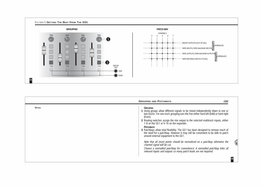
GROUPINGUsing groups allow different signals to be mixed independently down to one ortwo tracks. For one track grouping turn the Pan either hard left (0dd) or hard right(Even).Routing switches assign the mix output to the selected multitrack inputs, either1-8 on the GS1 or 9-16 on the expander.PATCHBAYSPatchbays allow total flexibility. The GS1 has been designed to remove much ofthe need for a patchbay. However it may still be convenient to be able to patcharound external equipment to the GS1.
Note that all insert points should be normalised on a patchbay otherwise thechannel signal will be cut.Choose a normalled patchbay for convenience: A normalled patchbay links allrelevant inputs and outputs so many patch leads are not required.
GROUPING AND PATCHBAYS
32
5
GS1
NOTES
31
SECTION 5 GETTING THE BEST FROM THE GS1
31 2
31 2
31 2
31 2
31 2
31 2
31 2
31 2
GS1
31 2
31 2
31 2
31 2
31 2
31 2
31 2
31 2
OPTIONAL EXPANDERWHDWEIGHT
315mm59mm496mm5kg/11lb
GS1WHDWEIGHT
520mm59mm496mm7.5kg/16.5lb
D
W W
D
H
GS1Compact Studio Consolemeterbridge
METERBRIDGEWHDWEIGHT
500mm175mm22mm1.5kg/3.3lb
PSUWHDWEIGHT
108mm60mm77mm1kg/2.2lb
OPTIONAL
W
H
D
D
W
GS1
34
6
33
SECTION 6 SPECIFICATIONS AND OPTIONS
MONO JACK
GRAPHIC
UNBALANCED JACK
TIPRINGSLEEVE
INSERT JACK
SLEEVE RINGTIP
TIPRINGSLEEVE
DIRECT OUTFROM INSERT
SLEEVE TIP
LINK RING TO GND
1/4" JACKS RCA PHONO
SIGNAL GND
BALANCED JACK
SENDLINK TO TIPGND
SHIELD
SIGNALGND -GND
SLEEVE
RING TIP
+ GNDGND +
RING
:::
SENDRETURNGND
:::
GS1 SOCKETS
3
2
1
UNBALANCED(SWITCH OFF PHANTOM POWER)
LINK PIN 3 TO PIN 1
THRU OUT
MIDI
POWER INPUT SOCKET
BALANCED PIN 2 = +PHASEPIN 3 = - PHASEPIN 1 = OV
3-PIN XLR PLUGS
18V AC18V AC
IN
1
3
2
FROM SOURCE
1
3
2
GS1 MIC INPUT
MALE PLUG WIRING VIEW
3
2
1
CENTRE TAP
GS1
36
6
35
SECTION 6 SPECIFICATIONS AND OPTIONS CONNECTOR DIAGRAMS
GS1AUDIO SPECIFICATIONS
38
6
37
SECTION 6 SPECIFICATIONS AND OPTIONS MIDI IMPLEMENTATIONS
G#A0
A#0B0C1C#1D1D#1E1F1
F#1G1
CH123456789101112
DEC323334353637383940414243
HEX202122232425262728292A2B
BA S I C GS1
HEX DEC CH2C 44 13 G#12D 45 14 A12E 46 15 A#12F 47 16 B130 48 17 C230 49 18 C#232 50 19 D233 51 20 D#2
G#1A1A#1B1C2
C#2D2D#2
CH1314151617181920
DEC4445464748495051
HEX2C2D2E2F30303233
TR A N S M I T T E D NO T E
9n kk v1 kk v2n - MIDI Channel (must be console’s channel)kk - Note number (see table 1 & 2)v1 => 40H Mute ON
<= 3FH Mute OFFv2 = 0RE C E I V E D NO T E
9n kk vvn - MIDI channel = 16kk - Note number (see table 1 & 2)vv => 40H Mute ON
<= 3FH Mute OFF= 0 IGNORED
PA T C H RE C A L L
Cn pwhere
n - MIDI channel = 16p - Program Change Number
GS1 EX P A N D E R
F0, 7F, 7F, 06, 44, 02, 00, 08, F7F0, 7F, 7F, 06, 01, F7F0, 7F, 7F, 06, 02, F7F0, 7F, 7F, 06, 05, F7
F0, 7F, 06, 04, F7F0, 7F, 7F, 06, 4C, 02, 08, 01, F7
LOCATESTOPPLAYREWFWD
SET LOCATE
123456
MMC ME S S A G ENA M EFKE Y
CF 00CF 01CF 02CF 03CF 04CF 05
123456
PR O G CH N GME S S A G E
FKE Y
NOTESOU T P U T S
2 Track out Unbal. RCA Phono 50ohmsGroup out Unbal. RCA Phono 50ohmsAux. out Unbal. 1/4” Jack 50ohmsInserts sends Unbal. 1/4” Jack - tip sends 50ohmsMonitor out Unbal. RCA Phono 50ohmsPhones out Unbal. tip left, ring right for 8-400ohms Headphones
PA R A M E T E R
Max O/p Level +21dBu into 2k ohmsMeters Peak responding, 0VU=+4dBu or -10dBV as selectedFrequency Response 10Hz to 30kHz +0/ -1dBDistortion - THD (Line to Mix out @ 1kHz) 0.006%Crosstalk >75dB @ 1kHzNoise - 22Hz to 22kHz MIC EIN -127dB into 150ohmsNoise - Pre-amp @ 0dB -88dBuNoise - Mix -82dBu
IN P U T S
Mic In Bal. pin 2 hot, 3 cold >2kohms var -60 to -20dBuLine In Bal. pin 2 hot, 3 cold >25kohms var -30 to +10dBuLine In Unbal. tip hot, ring gnd >25kohms var -30 to +10dBuStereo In Unbal. tip hot, ring gnd >10kohms +4dBu or -10dBVSereo Rtn Unbal. tip hot, ring gnd >5kohms +4dBu or -10dBV2 Track Rtn Unbal. >10kohms +4dBu or -10dBVTape Return Unbal. >5kohms +4dBu or -10dBVInsert Return Unbal. ring return >5kohms +4dBu or -10dBV
+4dBu, or -10dBVDepending upon operating levelset +21dBu max.
Patch ModeMMC Mode
9F 5D 209F 5F 209F 5E 209F 5B 209F 5C 209F 58 20
RECORDSTOPPLAYREWFWD
CYCLE
123456
MIDI MESS.(P R E S S )
NA M EFKE Y
9F 5D 009F 5F 009F 5E 009F 5B 009F 5C 009F 58 00
A5B5A#5G5G#5E5
MIDI MESS.(R E L E A S E )
NO T E
MIDI Mode

Allen & Heath, Kernick Industrial Estate, Penryn, Cornwall, TR10 9LU, England. Telephone : (44) 01326 372 070 Facsimile : (44) 01326 377 097
PUBLICATION AP2061 ISSUE 2 PRINTED IN ENGLAND ON PAPER FROM A SUBSTAINABLE WOODSTOCK. DESIGN BY INVOGRAPHIS