Embed Size (px)
Citation preview

LET, 686 04 KUNOVICE, CZECH REPUBLIC
SAILPLANE FLIGHT MANUALSerial Nos.eligible : 938101, and subsequend
Model : L 23 SUPER - BLANIK
Serial No. :
Registration :
948123
N392BA
Document No. : Do - L23 . 1012.5
Date of Issue : December 1, 1993
This sailplane Flight Manual is FAA Aproved for U.S. - registered sailplanesin accordance with provision of 14 CFR Part 21.29, and as reguired by FAAType Certificate Data Sheet No. G60EU.
Approved by The Civil Aviation Inspectorate of The Czech Republic in Prague.
Signature : ^^^^^^^^^^^^^^^^^^^^^^^^^^^^^^^^^^^^^^^^7
Authority : CAI, Prague
Stamp :
Original date of approval : December 6, 1993
I This Sailplane Flight Manual must be carried in the sailplane at all times.
This sailplane is to be operated in compliance with information andlimitations contained herein.
1F .f-e.
I - ‘ 9 I*C
L 23 SUPER - BLANIK686 04 KUNOVICECZECH REPUBLIC SAILPLANE FLIGHT MANUAL Do - L 23. 1012.5
0.1. RECORD OF REVISIONS
Any revision or amendment of the present Manual will be issued in the
Iform of Bulletins, approved by the Civil Aviation Authority of the CzechRepublic, supplement of which will contain new (revised) pages. User’sduty is to make a note about revisions in the Record of revisions and toreplace existing pages with revised and effective ones. Revised oramended parts of the text will be indicated by a vertical line in the lefthand margin and the revision No. and the date will be shown on thebottom left hand of the page.
Rev.N o .
1.
A f f e c t e dS e c t i o n
0, 2, 6, 7
4. N o ta f f e c t e d
A f f e c t e d p a g e s D a t e
0-l, 0-3, 2-5,2-10, 2-11, 6-5,
6-6, 6-7, 7-1, 7-4,7 - 5
Dec 20/95
0-1, 0-3, 1-1, 1-3,1-4, 1-5, 2-10,2-11, 3-1, 3-2,
3-3, 3-4, 3-5, 4-5,4-6, 4-7, 7-4, 7-5,
7 - 6
0-1, 0-3, 0-4, 9-1, Jan 13/999-2, 9-3
BulletinN o .
L23/026a
L23/029a
L23/030a
L23/035a
Date ofBulletin
a p p r o v a l
Date inserted andsignature
Dec 2/96
Jan 28/99
Jan 13/99 0 0-1
L 23 SUPER - BLANIK686 04 KUNOVICECZECH REPUBLIC SAILPLANE FLIGHT MANUAL Do - L 23. 1012.5
Rev. A f f e c t e d A f f e c t e d p a g e sN o . S e c t i o n
D a t e BulletinN o .
Date ofBulletin
a p p r o v a l
Date inserted ands i g n a t u r e
Dec 1/933 0-2
L 23 SUPER - BLANIK686 04 KUNOVICECZECH REPUBLIC SAILPLANE FLIGHT MANUAL Do - L 23. 1012.5
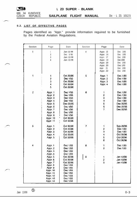
0.2. LIST OF EFFECTIVE PAGES
Pages identified as "Appr." provide information reguired to be furnishedby the Federal Aviation Regulations.
Section
0
P a g e D a t e
1 Jan 13/992 Dec 1/933 Jan 13/994 Jan 13/99
S e c t i o n
4
Page
Appr. 15Appr. 1 6A p p r . 17Appr. 1 8Appr. 19Appr. 20Appr. 21Appr. 22
D a t e
Dec 1/93Dec 1/93Dec 1/93Dec 1/93Dec 1/93Dec 1/93Dec 1/93Dec 1/93
Jan 13/99 0 0-3
L 23 SUPER - BLANIK686 04 KUNOVICECZECH REPUBLIC SAILPLANE FLIGHT MANUAL Do - L 23. 1012.5
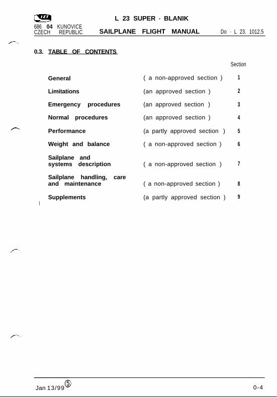
0.3. TABLE OF CONTENTS
General
Limitations
Emergency procedures
Normal procedures
Performance
Weight and balance
Sailplane andsystems description
Sailplane handling, careand maintenance
ISupplements
( a non-approved section )
(an approved section )
(an approved section )
(an approved section )
(a partly approved section )
( a non-approved section )
( a non-approved section )
( a non-approved section )
(a partly approved section )
Section
1
2
3
4
5
6
7
8
9
Jan 13/990 0-4
L 23 SUPER - BLANIK686 04 KUNOVICECZECH REPUBLIC SAILPLANE FLIGHT MANUAL Do - L 23. 1012.5
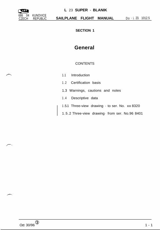
SECTION 1
General
CONTENTS
1.1 Introduction
1 . 2 Certification basis
1.3 Warnings, cautions and notes
1 . 4 Descriptive data
1 .5.1 Three-view drawing - to ser. No. xx 8320
1.5.2 Three-view drawing - from ser. No.96 8401
Oct 30/960 1 - 1
L 23 SUPER - BLANIK686 04 KUNOVICECZECH REPUBLIC SAILPLANE FLIGHT MANUAL Do - L 23. 1012.5
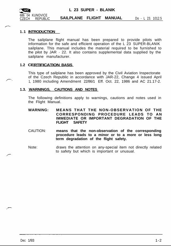
1.1 INTRODUCTION
The sailplane flight manual has been prepared to provide pilots withinformation for the safe and efficient operation of the L 23 SUPER-BLANIKsailplane. This manual includes the material required to be furnished tothe pilot by JAR - 22. It also contains supplemental data supplied by thesailplane manufacturer.
1.2 CERTIFICATION BASIS
This type of sailplane has been approved by the Civil Aviation Inspectorateof the Czech Republic in accordance with JAR-22, Change 4 issued April1, 1980 including Amendment 22/86/1 Eff. Oct. 22, 1986 and AC 21.17-2.
1.3. WARNINGS, CAUTIONS AND NOTES
The following definitions apply to warnings, cautions and notes used inthe Flight Manual.
WARNING: MEANS THAT THE NON-OBSERVATION OF THECORRESPONDING PROCEDURE LEADS TO ANIMMEDIATE OR IMPORTANT DEGRADATION OF THEFLIGHT SAFETY
CAUTION: means that the non-observation of the correspondingprocedure leads to a minor or to a more or less longterm degradation of the flight safety.
Note: draws the attention on any-special item not directly relatedto safety but which is important or unusual.
Dec 1/93 1-2
L 23 SUPER - BLANIK686 04 KUNOVICECZECH REPUBLIC SAILPLANE FLIGHT MANUAL Do - L 23. 1012.5
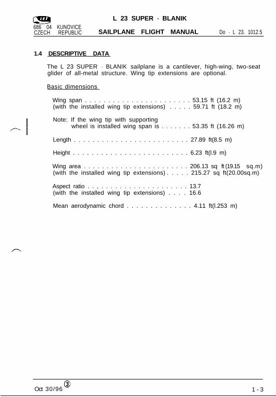
1.4 DESCRIPTIVE DATA
The L 23 SUPER - BLANIK sailplane is a cantilever, high-wing, two-seatglider of all-metal structure. Wing tip extensions are optional.
Basic dimensions
Wing span . . . . . . . . . . . . . . . . . . . . . . . 53.15 ft (16.2 m)(with the installed wing tip extensions) . . . . . 59.71 ft (18.2 m)
Note: If the wing tip with supportingwheel is installed wing span is . . . . . . . 53.35 ft (16.26 m)
Length . . . . . . . . . . . . . . . . . . . . . . . . . 27.89 ft(8.5 m)
Height . . . . . . . . . . . . . . . . . . . . . . . . . 6.23 ft(l.9 m)
Wing area . . . . . . . . . . . . . . . . . . . . . . . 206.13 sq ft (19.15 sq.m)(with the installed wing tip extensions) . . . . . 215.27 sq ft(20.00sq.m)
Aspect ratio . . , . . . . . . . . . . . . . . . . . . . 13.7(with the installed wing tip extensions) . . . . 16.6
Mean aerodynamic chord . . . . . . . . . . . . . . 4.11 ft(l.253 m)
Oct 30/960
1 - 3
L 23 SUPER - BLANIK686 04 KUNOVICECZECH REPUBLIC SAILPLANE FLIGHT MANUAL Do - L 23. 1012.5
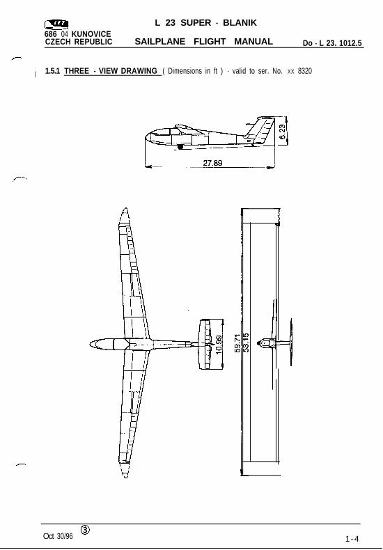
I 1.5.1 THREE - VIEW DRAWING ( Dimensions in ft ) - valid to ser. No. XX 8320
III
i
Oct 30/96 01-4
L 23 SUPER - BLANIK686 04 KUNOVICECZECH REPUBLIC SAILPLANE FLIGHT MANUAL Do - L 23. 1012.5
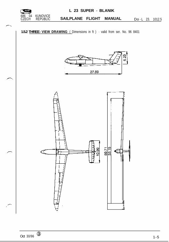
1.5.2 THREE - VIEW DRAWING ( Dimensions in ft ) - valid from ser. No. 96 8401
Oct 30/96 01-5

L 23 SUPER - BLANIK
686 04 KUNOVICECZECH REPUBLIC SAILPLANE FLIGHT MANUAL Do - L 23. 1012.5
SECTION 2
Limitations
C O N T E N T S
2.1 Introduction
2.2 Airspeed
2.3 Airspeed indicator markings
2.4 Weight
2.5 Centre of gravity
2.6 Approved manoeuvres
2.7 Manoeuvring load factors
2 . 8 Flight crew
2.9 Kinds of operation
2.10 Minimum equipment
2.11 Aerotow and winch-launching
2.12 Other limitations
2.13 Limitation placards
Appr.Dec 1/93 2 - 1

L 23 SUPER - BLANIK686 04 KUNOVICECZECH REPUBLIC SAILPLANE FLIGHT MANUAL Do - L 23. 1012.5
2 . 1 INTRODUCTION
Section 2 includes operating limitations and basic placards necessary forsafe operation of the sailplane, its standard systems and standardequipment. The limitations in this section are FAA approved by the CAI,Czech Republic. The values in parentheses are valid only when using wingtip extensions.
2.2 AIRSPEED
Speed (KIAS) Remarks
VNE Never exceed speed up 124 Do not exceed this speed in anyto a pressure altitude of operation and do not use more than13, 780 ft 1/3 of control deflection
VRA Rough air speed 8 6 Do not exceed this speed except insmooth air, and then only withcaution, Examples of rough air arelee-wave rotor thunderclouds etc.
VA Manoeuvring speed 81 Do not make full or abrupt controlmovement above th is speed,because under certain conditionsthe sailplane may be overstressedby full control movement
VW Maximum winch- 65 Do not exceed this speed duringlaunching speed winch- or autotow-launching
VT Maximum aerotowing 81 Do not exceed this speed duringspeed aerotowing
VLo Maximum landing gear 124 Do not extend or retract the landingoperating speed gear above this speed
Note: VNE airspeed limits above 13,780 ft Pressure Altitude are redu-ced as follows:
*
Pressure Altitude ft * 13,780 20,000 25,000 30,000 35,000
VNE KIAS 124 124 116 108 100(114) (105) (97) (89)
* : Altimeter Setting at 29.92 in.Hg.
A p p r .Dec 1/93 2-2

L 23 SUPER - BLANIK686 04 KUNOVICECZECH REPUBLIC SAILPLANE FLIGHT MANUAL
2 . 3 A I R P
Do - L 23. 1012.5
N o r m a l O p e r a t i n g Range .(Lower limit is maximum weight
oeuvres must be conductedcaution and only in smooth
Yellow triangle
operations
Approach speed a t m a x i m u mweight.
2 . 4 W E I G H T L I M I T S
Maximum take-off and landing weight:
- with two occupants . . . . . . . . . . 1124 lb
- with one pilot . . . . . . . . . . . . . . 925 lb
Empty weightwith standard equipment . . . . . . . . 683 lb 2 2 %(695 lb * 2%)
and the corresponding centreof gravity position . . . . . . . . . . . . 67.30 -c 1% MAC(68.30 t 2% MAC)
Maximum weight of all non lifting parts 778 lb (767 lb)
Note : Refer to weight and Balance ( Section 6.0 ) to determine actualempty weight / c.g. as established by the installed equipmentand manufacturing tolerances.
( Cont. )
Appr.Dec 1/93 2 - 3
L 23 SUPER - BLANIK686 04 KUNOVICECZECH REPUBLIC SAILPLANE FLIGHT MANUAL Do - L 23. 1012.5
Pilot’s weight (including parachute):
- minimum pilot’s weight (solo ) . . . . . . . 154 lb
It is necessary to use front seat removable ballast of 33 lb when flown soloby a pilot (including parachute) weighing less than 154 lb in the frontcockpit.
Note: Installation of the front seat ballast is described in Section7, paragraph 7.2 of this Flight Manual.
- maximum pilot’s weight ( solo ) . . . . . . 242 lb
Maximum useful load ( occupants,baggage, optional equipment ) . . . . . . . 440 lb (430 lb)
Maximum baggage compartment load . . . 22 lb
Appr.Dec 1/93 2-4

L 23 SUPER - BLANIK
686 04 KUNOVICECZECH REPUBLIC SAILPLANE FLIGHT MANUAL Do - L 23. 1012.5
2.5 CENTRE OF GRAVITY
Centre of gravity range
- front limit . , . . . . . . . . . . . . . . . . . . . . 23 % MAC i.e. 4.397 in(112 mm) aft ofreference datum
- rear limit . . . . . . . . . . . . . . . . . . . . . . 40 % MAC i.e. 12.783 in(325 mm) aft ofreference datum
Wing tip extensions installation moves the center of gravity of the emptysailplane 1% MAC (0.493 in = 12.53 mm) to the back.
The reference datum is located 93.6 in aft of the sailplane nose.
2.6 APPROVED MANOEUVRES ( UTILITY CATEGORY )
Sailplane is certified in the Utility Category.With the installed wing tip extensions all aerobatic manoeuvres areprohibited.
Manoeuvre Airspeeds - KIAS Procedures
SOLO DUAL ENTRY RECOVERY
Loop 8 6 9 7 x Sec t ion 4 . 4 . 6 item
Stall turn 9 2 9 7 x Sec t ion 4 . 4 . 6 item 2.
Lazy Eight 9 7 9 7 x Sec t ion 4 . 4 . 6 item
Spin 3 2 3 2 x Sec t ion 4 . 4 . 6 i t em8 6 8 6 x
Chandelle (climbing) 9 7 9 7 x Sec t ion 4 . 4 . 6 item 5.
Steep turn 9 2 9 7 x Sec t ion 4 . 4 . 6 item
Appr.Dec 20/95 (i)
.a
2-5

L 23 SUPER - BLANIK686 04 KUNOVICECZECH REPUBLIC SAILPLANE FLIGHT MANUAL Do - L 23. 1012.5
2.7. MANOEUVRING LOAD FACTORS
2
1
0
- 1
- 2
- 3
1fl -su./-
-WEIGHT 1124 LBI I I I
1 KIAS
LB
FIG. 2 - 1
2.0 FLIGHT CREW
Minimum - one pilot. Maximum number of occupants is two. If thesailplane is to be flown solo, the pilot must be sitting in the front seat andhis weight (including parachute) must be 154 lb at least. If the pilot’sweight is less than 154 lb, it is necessary to use the cushion with 33 lbballast.
WARNING: THE REAR SEAT MUST BE SECURED AGAINST FOLDINGAND SAFETY HARNESSES ON THE REAR SEAT MUST BECONNECTED, DRAWN TOGETHER AND SECURED.
2.9 KINDS OF OPERATION
The sailplane is approved for Day VFR operations. Cloud- flying ispermitted where operational regulations permit, and the minimum reguiredeguipment is installed and operable.
( Cont. )
Appr.Dec 1/933 2-6
L 23 SUPER - BLANIK686 04 KUNOVICECZECH REPUBLIC SAILPLANE FLIGHT MANUAL Do - L 23. 1012.5
WARNING: 1. OPERATIONS IN ICING CONDITIONS ARE PROHIBITED. OPERA-TIONS ARE LIMITED BY THE INSTALLED EQUIPMENT ASLISTED IN SECTION 6.
2. AEROBATIC FLIGHT TIME MUST BE RECORDED IN THESAILPLANE LOG BOOK TO COMPLY WITH CONTINUEDAIRWORTHINESS REQUIREMENTS.
3. ALL AEROBATIC MANOEUVRES ARE PROHIBITED WITHINSTALLED WING TIP EXTENSION.
4. WITH INSTALLED WING EXTENSIONS:ALL FLIGHT TIME WITH WING EXTENSIONS MUST BERECORDED IN THE SAILPLANE LOG BOOK TO COMPLY WITHCONTINUED AIRWORTHINESS REQUIREMENTS.
5. THE NUMBER OF WINCH AND AEROTOW LAUNCHES MUST BERECORDED IN THE SAILPLANE LOG BOOK TO COMPLY WITHCONTINUED AIRWORTHINESS REQUIREMENTS.
2 . 1 0 M I N I M U M EQUIPMENT
Instruments and minimum equipment must be approved types.
A. Instruments All Operations:
- Airspeed indicator
- Altimeter
- Lap and shoulder straps
B. Additional Instruments required for Cloud flying:
- Magnetic compass
- Turn and bank indicator
- Variometer (Vertical Speed Indicator)
Appr.Dec 1/933 2-7
L 23 SUPER - BLANIK
686 04 KUNOVICECZECH REPUBLIC SAILPLANE FLIGHT MANUAL Do - L 23. 1012.5
2.11 AEROTOW AND WINCH LAUNCHING
Aerotow
- the maximum cable strength or cable safety device (weak link) strengthis 1460 lb.
- maximum permissible speed VT = 81 KIAS
- the minimum cable length for aerotowing is 50 ft , recommended lengthis 100-130 ft .
Winch-launching
- the maximum cable strength or cable safety device ( weak link )is 1460 lb .
- maximum permissible speed Vw=65 KIAS
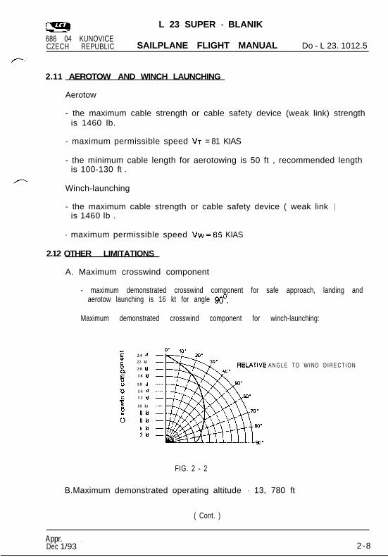
2.12 OTHER LIMITATIONS
A. Maximum crosswind component
- maximum demonstrated crosswind component for safe approach, landing andaerotow launching is 16 kt for angle 90’.
Maximum demonstrated crosswind component for winch-launching:
E 24 nQ)5
22 kl
20 n18 h
z 18 kt
a 14 nc 12 n.-sv)
10 kt
2 8kt0 6H
4h2kl
A N G L E T O W I N D D I R E C T I O N
FIG. 2 - 2
B.Maximum demonstrated operating altitude - 13, 780 ft
( Cont. )
Appr. ??
Dec 1/933 2-8
L 23 SUPER - BLANIK686 04 KUNOVICECZECH REPUBLIC SAILPLANE FLIGHT MANUAL Do - L 23. 1012.5
C. Maximum Tire Pressure 37 psi.
D. Continued Airworthiness Life Limits:
The initial sailplane service life is specified to 6000 flight hours and30000 landings under the following operating conditions:
- Max. 4.83 take-offs per 1 flight hour;
- The winch launching - aerotow take-off ratio is 5 : 1;
- Crew: 35% double, 65% single;
- Elementary training-to-advanced training and to performance soaringratio is 40% : 60%, whereby the aerobatics share is 2% of the totaloperation.
Sailplane life LB versus operation with wing tip extensions isLB = 6000 - 25.x (where x is operation with wing tip extensions inpercents of the total operation time)
Appr.Dec 1/93 2-9
L 23 SUPER - BLANIK686 04 KUNOVICECZECH REPUBLIC SAILPLANE FLIGHT MANUAL Do - L 23. 1012.5
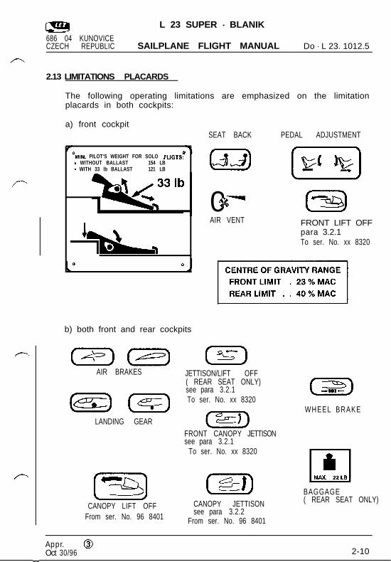
2.13 LIMITATIONS PLACARDS
The following operating limitations are emphasized on the limitationplacards in both cockpits:
a) front cockpitSEAT BACK PEDAL ADJUSTMENT
‘MIN. PILOT‘S WEIGHT FOR SOLO FLIGTS:- WITHOUT BALLAST 154 LB- WITH 33 lb BALLAST 121 LB
11%
b) both front and rear cockpits
AIR BRAKES
LANDING GEAR
E3CANOPY LIFT OFF
From ser. No. 96 8401
[Gx]05’3%. ‘8, 0-n4AIR VENT FRONT LIFT OFF
para 3.2.1To ser. No. xx 8320
JETTISON/LIFT OFF( REAR SEAT ONLY)see para 3.2.1To ser. No. xx 8320
FRONT CANOPY JETTISONsee para 3.2.1
To ser. No. xx 8320
paraCANOPY JETTISONsee para 3.2.2
From ser. No. 96 8401
(z5)WHEEL BRAKE
BAGGAGE( REAR SEAT ONLY)
Appr. @Oct 30/96 2-10
L 23 SUPER - BLANIK686 04 KUNOVICECZECH REPUBLIC SAILPLANE FLIGHT MANUAL Do - L 23. 1012.5
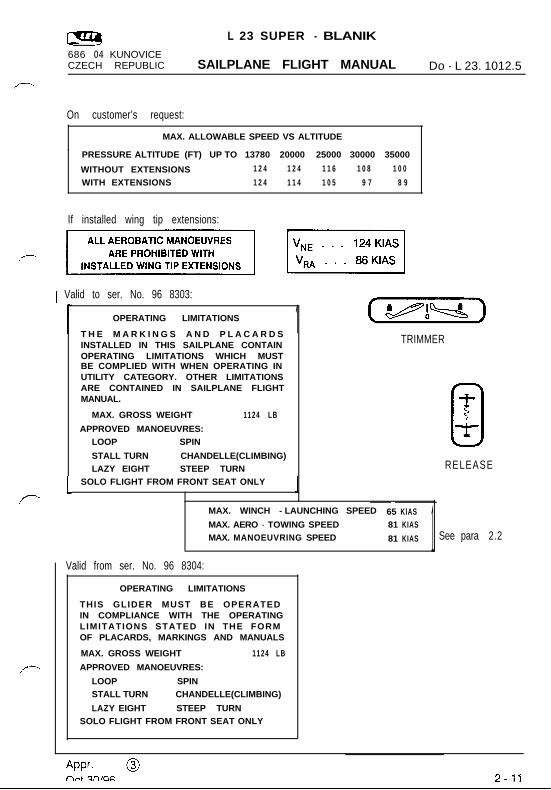
On customer’s request:.
MAX. ALLOWABLE SPEED VS ALTITUDE
PRESSURE ALTITUDE (FT) UP TO 13780 20000 25000 30000 35000
WITHOUT EXTENSIONS 1 2 4 1 2 4 1 1 6 1 0 8 1 0 0
WITH EXTENSIONS 1 2 4 1 1 4 1 0 5 9 7 8 9
If installed wing tip extensions:
1 Valid to ser. No. 96 8303:
1
OPERATING LIMITATIONS
T H E M A R K I N G S A N D P L A C A R D SINSTALLED IN THIS SAILPLANE CONTAINOPERATING LIMITATIONS WHICH MUSTBE COMPLIED WITH WHEN OPERATING INUTILITY CATEGORY. OTHER LIMITATIONSARE CONTAINED IN SAILPLANE FLIGHTMANUAL.
MAX. GROSS WEIGHT 1124 LB
APPROVED MANOEUVRES:LOOP SPIN
STALL TURN CHANDELLE(CLIMBING)LAZY EIGHT STEEP TURN
SOLO FLIGHT FROM FRONT SEAT ONLY
1 (U)TRIMMER
0TTRELEASE
IMAX. WINCH - LAUNCHING SPEED 65 KIASMAX. AERO - TOWING SPEED 81 KIASMAX. MANOEUVRING SPEED 81 KIAS
Valid from ser. No. 96 8304:
OPERATING LIMITATIONS
THIS GLIDER MUST BE OPERATEDIN COMPLIANCE WITH THE OPERATINGLIMITATIONS STATED IN THE FORMOF PLACARDS, MARKINGS AND MANUALS
MAX. GROSS WEIGHT 1124 LB
APPROVED MANOEUVRES:
LOOP SPINSTALL TURN CHANDELLE(CLIMBING)
LAZY EIGHT STEEP TURNSOLO FLIGHT FROM FRONT SEAT ONLY
1 See para 2.2
L 23 SUPER - BLANIK
686 04 KUNOVICECZECH REPUBLIC SAILPLANE FLIGHT MANUAL Do - L 23. 1012.5
SECTION 3
Emergency procedures
CONTENTS
3 . 1 Introduction
3 . 2 . 1 Canopy jettison - valid to ser. No. XX 8 3 2 0
3.2.2 Canopy jettison - valid from ser. No. 96 8401
3 . 3 Bailing Out
3 . 4 Stall recovery
3.5 Spin recovery
3.6 Spiral Dive Recovery
Appr. @Oct 30/96 3 - 1
L 23 SUPER - BLANIK
686 04 KUNOVICECZECH REPUBLIC SAILPLANE FLIGHT MANUAL Do - L 23. 1012.5
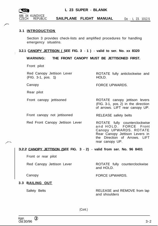
3.1 INTRODUCTION
Section 3 provides check-lists and amplified procedures for handlingemergency situatins.
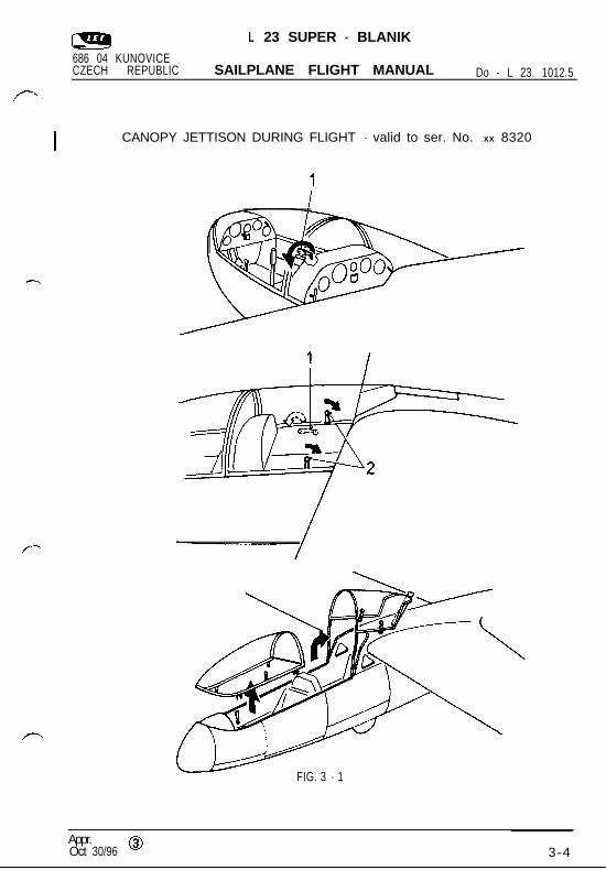
I3.2.1 CANOPY JETTISON ( SEE FIG. 3 - 1 ) - valid to ser. No. xx 8320
WARNING: THE FRONT CANOPY MUST BE JETTISONED FIRST.
Front pilot
Red Canopy Jettison Lever(FIG. 3-1, pos. 1)
Canopy
Rear pilot
Front canopy jettisoned
ROTATE fully anticlockwise andHOLD.
FORCE UPWARDS.
ROTATE canopy jettison levers(FIG. 3-1, pos. 2) in the directionof arrows. LIFT rear canopy UP.
Front canopy not jettisoned RELEASE safety belts
Red Front Canopy Jettison Lever ROTATE fully counterclockwisea n d H O L D . FORCE FrontCanopy UPWARDS. ROTATERear Canopy Jettison Levers inthe Direction of Arrows. LIFTrear canopy UP.
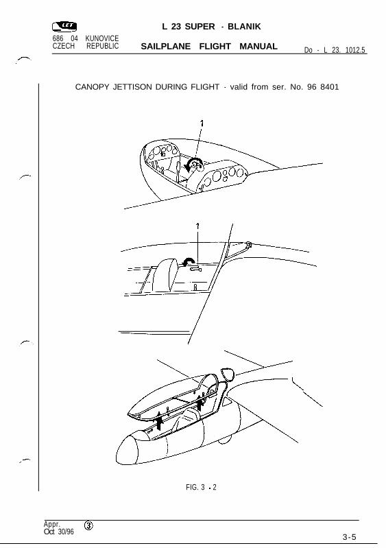
3.2.2 CANOPY JETTISON (SEE FIG. 3 - 2) - valid from ser. No. 96 8401
Front or rear pilot
Red Canopy Jettison Lever ROTATE fully counterclockwiseand HOLD.
Canopy FORCE UPWARDS.
3.3 BAILING OUT
Safety Belts RELEASE and REMOVE from lapand shoulders
(Cont.)
Appr. @Oct 30/966 3-2
L 23 SUPER - BLANIK686 04 KUNOVICECZECH REPUBLIC SAILPLANE FLIGHT MANUAL Do-L23. 1012.5
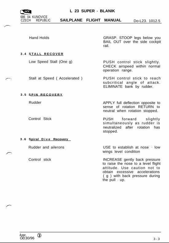
Hand Holds
3 . 4 S T A L L R E C O V E R
Low Speed Stall (One g)
Stall at Speed ( Accelerated )
3 . 5 S P I N R E C O V E R Y
Rudder
Control Stick
3 . 6 Spiral D i v e Recovery
Rudder and ailerons
Control stick
GRASP. STOOP legs below youBAIL OUT over the side cockpitrail.
PUSH control st ick sl ight ly.CHECK airspeed within normaloperation range.
PUSH control st ick to reachsubcri t ical angle of at tack.ELIMINATE bank by rudder.
APPLY full deflection opposite tosense of rotation RETURN toneutral when rotation stopped.
PUSH forward sl ight lys imul taneously as rudder isneutralized after rotation hasstopped.
USE to establish at nose - lowwings level condition
INCREASE gently back pressureto raise the nose to a level flightatt i tude. Use caution not toobtain excessive accelerations( g ) with back pressure duringthe pull - up.
Appr. @Oct 30/960/96 3 - 3
L 23 SUPER - BLANIK686 04 KUNOVICECZECH REPUBLIC SAILPLANE FLIGHT MANUAL Do - L 23. 1012.5
CANOPY JETTISON DURING FLIGHT - valid to ser. No. XX 8320
FIG. 3 - 1
Appr.Oct 30/96 0 3-4
L 23 SUPER - BLANIK686 04 KUNOVICECZECH REPUBLIC SAILPLANE FLIGHT MANUAL Do - L 23. 1012.5
CANOPY JETTISON DURING FLIGHT - valid from ser. No. 96 8401
FIG. 3 - 2
\
Appr. @Oct 30/96
3-5

L 23 SUPER - BLANIK
686 04 KUNOVICECZECH REPUBLIC SAILPLANE FLIGHT MANUAL Do - L 23. 1012.5
SECTION 4
Normal procedures
CONTENTS
4.1 Introduction
4.2 Rigging and de-rigging
4 . 3 Preflight Inspection
4 . 4 Normal operations and recommended speeds
4.4.1 Take-off and climb
4.4.2 Flight
4.4.3 Approach
4.4.4 Landing
4.4.5 Use of air brakes
4.4.6 Basic aerobatics
Appr.Dec 1/93 4 - 1
L 23 SUPER - BLANIK
686 04 KUNOVICECZECH REPUBLIC SAILPLANE FLIGHT MANUAL Do - L 23. 1012.5
4.1 INTRODUCTION
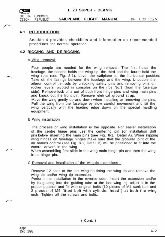
Sect ion 4 provides checkl is ts and informat ion on recommendedprocedures for normal operation.
4.2 RIGGING AND DE-RIGGING
A. Wing removal
Four people are needed for the wing removal. The first holds thefuselage, the second holds the wing tip, the third and the fourth hold thewing root (see Fig. 8-1). Level the sailplane to the horizontal position.Take off the fairings between the fuselage and the wing. Uncouple theaileron control tie rods by unlocking safety pins and removing pins onrocker levers, pivoted in consoles on the ribs No.1 (from the fuselageside). Remove lock pins out of both front hinge pins and wing main pinsand knock out the front pin. Remove eletrical ground strap.Move the wing gently up and down when installing or removing the pins.Pull the wing from the fuselage by slow careful movement and sit thewing vertically with the leading edge down on the special handlingequipment.
B Wing installation
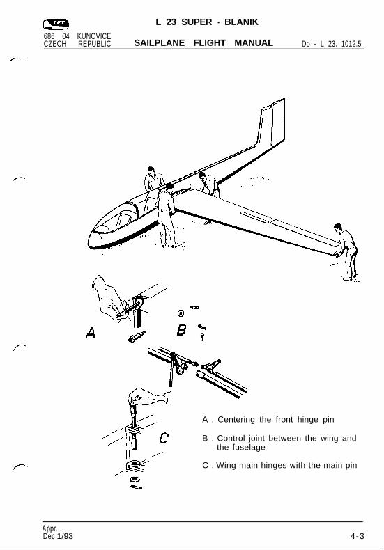
The process of wing installation is the opposite. For easier installationof the centre hinge pins use the centering pin (or installation driftpin) before inserting the main pins (see Fig. 8-1, Detail A). When slippingwing hinges on fuselage hinges make sure that the globular joint of theair brakes control (see Fig. 8-1, Detail B) will be positioned to fit into thecontrol drivers in the wing.When assembling first slide in the wing main hinge pin and then the wingfront hinge pin.
C Removal and installation of the wing tip extensions
Remove 12 bolts at the last wing rib fixing the wing tip and remove thewing tip and/or wing tip extension.Perform the installation in the reverse oder. Insert the extension and/orby its guiding into the guiding tube at the last wing rig, adjust it in theproper position and fix with original bolts (10 pieces of M4 sunk bolt and2 pieces of M5 f i t ted bolt with cyl inder head ) at both the wingends. Tighten all the screws and bolts.
( Cont. )
Appr.Dec 1/93 4-2
L 23 SUPER - BLANIK
686 04 KUNOVICECZECH REPUBLIC SAILPLANE FLIGHT MANUAL Do - L 23. 1012.5
A . Centering the front hinge pin
B . Control joint between the wing andthe fuselage
C . Wing main hinges with the main pin
Appr.Dec 1/93 4-3

L 23 SUPER - BLANIK
686 04 KUNOVICECZECH REPUBLIC SAILPLANE FLIGHT MANUAL Do - L 23. 1012.5
D. Horizontal stabilizer installation
The process of horizontal stabilizer installation is the opposite. It isrecommended that the hor izontal stabi l izer and the automat icconnection rocker levers of the elevator trim tab control on the verticalstabilizer, and on the horizontal stabilizer, are approximatelly parallel.
Remove the safety wire from the front pin of the horizontal stabilizers (infront of the leading edge of the vertical stabilizer on its top). Rotate thepin handle 180’ and pull out the pin. Elevate the horizontal stabilizerleading edge about 30 o up, slip out the horizontal stabilizers from pinsby pulling forward. It is recommended that the elevator to be in theneutral position during removal. Put the horizontal stabilizers on thespecial handling equipment support.
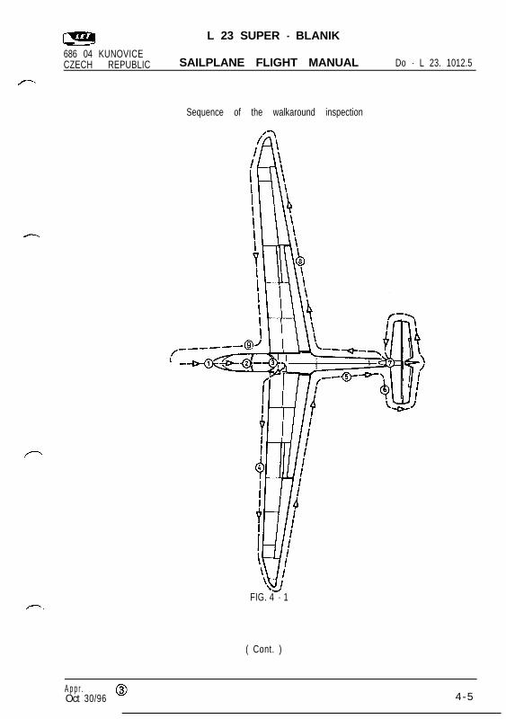
4.3 PREFLIGHT INSPECTION
The pilot must check the sailplane for proper condition in accordance withthe checklist walkaround inspection (before getting into the sailplane).It is recommended to perform the inspection as show in Fig. 4-1.
Appr.Dec 1/933 4-4
L 23 SUPER - BLANIK
686 04 KUNOVICECZECH REPUBLIC SAILPLANE FLIGHT MANUAL Do - L 23. 1012.5
Sequence of the walkaround inspection
FIG. 4 - 1
( Cont. )I
A p p r . @Oct 30/96 4-5

L 23 SUPER - BLANIK
686 04 KUNOVICECZECH REPUBLIC SAILPLANE FLIGHT MANUAL Do - L 23. 1012.5
4.3.1 WALKAROUND INSPECTION CHECKLIST
I
ItemNo.
Subject Check/activity
Front fuselage section1
Fuselage skin no damage
Left & right static probes ports clear
Cockpit canopy surface no damage or dirt
Nose pitot tube no damage or clogging
2Cockpi t
Instruments no damage
Altimeters correct setting QFE (QNH)
Radio station (if installed) proper operation
Front ventilation for season
Safety belts no damage
Landing gear3 .
Tire no damage, correct inflation
4 LLeft wing
Wing skin including leading no damageedge
Wing-tip fairing no damage or loose(wing tip extension)
Aileron skin no damage to fabr ic cover ortrailing edge
Ailerons free movement
Airbrake locking hinges locking no damage of hinges orcontrol tie rods
( Cont. )
Appr . @Oct 30/966 4-6
L 23 SUPER - BLANIK
686 04 KUNOVICECZECH REPUBLIC SAILPLANE FLIGHT MANUAL Do - L 23. 1012.5
ItemNo.
Subject Check/activity
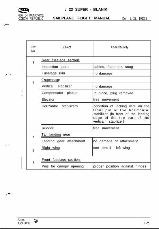
5Rear fuselage section
Inspection ports cables, fasteners snug
Fuselage skin no damage
6pennage
Vertical stabilizer no damage
Compensator pickup in place, plug removed
Elevator free movement
Horizontal stabilizers condition of locking wire on thef r o n t p i n o f t h e h o r i z o n t a lstabilizer (in front of the leadingedge of the top part of thevertical stabilizer)
Rudder free movement
7Tail landing gear
Landing gear attachment no damage of attachment
8Right wing see Item 4 - left wing
Front fuselage sec tion9
Pins for canopy opening proper position against hinges
Appr. @Oct 30/96 4 - 7
L 23 SUPER - BLANIK
686 04 KUNOVICECZECH REPUBLIC SAILPLANE FLIGHT MANUAL Do - L 23. 1012.5
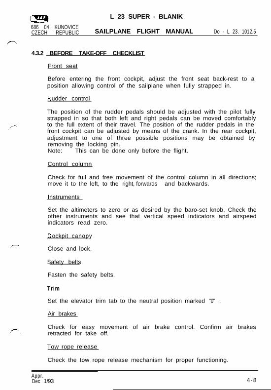
4.3.2 BEFORE TAKE-OFF CHECKLIST
Front seat
Before entering the front cockpit, adjust the front seat back-rest to aposition allowing control of the sailplane when fully strapped in.
udder control
The position of the rudder pedals should be adjusted with the pilot fullystrapped in so that both left and right pedals can be moved comfortablyto the full extent of their travel. The position of the rudder pedals in thefront cockpit can be adjusted by means of the crank. In the rear cockpit,adjustment to one of three possible positions may be obtained byremoving the locking pin.Note: This can be done only before the flight.
Control column
Check for full and free movement of the control column in all directions;move it to the left, to the right, forwards and backwards.
Instruments
Set the altimeters to zero or as desired by the baro-set knob. Check theother instruments and see that vertical speed indicators and airspeedindicators read zero.
ockpit canopy
Close and lock.
Safety belts
Fasten the safety belts.
Trim
Set the elevator trim tab to the neutral position marked "0" .
Air brakes
Check for easy movement of air brake control. Confirm air brakesretracted for take off.
Tow rope release
Check the tow rope release mechanism for proper functioning.
Appr.Dec 1/93 4-8
L 23 SUPER - BLANIK
686 04 KUNOVICECZECH REPUBLIC SAILPLANE FLIGHT MANUAL Do - L 23. 1012.5
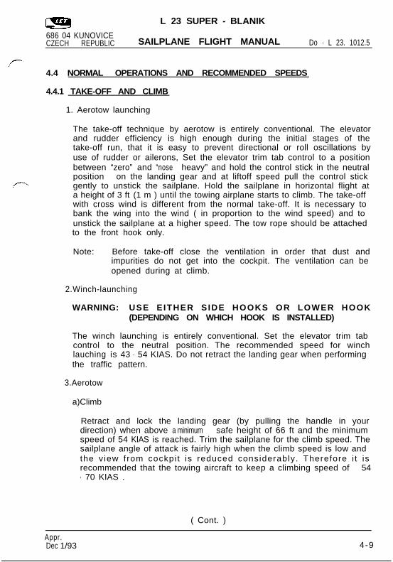
4.4 NORMAL OPERATIONS AND RECOMMENDED SPEEDS
4.4.1 TAKE-OFF AND CLIMB
1. Aerotow launching
The take-off technique by aerotow is entirely conventional. The elevatorand rudder efficiency is high enough during the initial stages of thetake-off run, that it is easy to prevent directional or roll oscillations byuse of rudder or ailerons, Set the elevator trim tab control to a positionbetween “zero” and “nose heavy” and hold the control stick in the neutralposition on the landing gear and at liftoff speed pull the control stickgently to unstick the sailplane. Hold the sailplane in horizontal flight ata height of 3 ft (1 m ) until the towing airplane starts to climb. The take-offwith cross wind is different from the normal take-off. It is necessary tobank the wing into the wind ( in proportion to the wind speed) and tounstick the sailplane at a higher speed. The tow rope should be attachedto the front hook only.
Note: Before take-off close the ventilation in order that dust andimpurities do not get into the cockpit. The ventilation can beopened during at climb.
2.Winch-launching
WARNING: USE EITHER SIDE HOOKS OR LOWER HOOK(DEPENDING ON WHICH HOOK IS INSTALLED)
The winch launching is entirely conventional. Set the elevator trim tabcontrol to the neutral position. The recommended speed for winchlauching is 43 - 54 KIAS. Do not retract the landing gear when performingthe traffic pattern.
3.Aerotow
a)Climb
Retract and lock the landing gear (by pulling the handle in yourdirection) when above a minimum safe height of 66 ft and the minimumspeed of 54 KIAS is reached. Trim the sailplane for the climb speed. Thesailplane angle of attack is fairly high when the climb speed is low andthe view from cockpit is reduced considerably. Therefore i t isrecommended that the towing aircraft to keep a climbing speed of 54- 70 KIAS .
( Cont. )
Appr.Dec 1/93 4-9

L 23 SUPER - BLANIK
686 04 KUNOVICECZECH REPUBLIC SAILPLANE FLIGHT MANUAL Do - L 23. 1012.5
The pilot should avoid overcontrolling.
Principles of aerotow are the same as for other sailplanes.
b) Level flight
The maximum speed for aerotow is 81 KIAS. It is necessary to trim thesailplane to reduce control forces and to decrease pilot fatigue duringlonger flights on tow. It is necessary to realize that control sensitivityincreases with flight speed.
Descending
A satisfactory rate of descent 390 - 590 ft/min can be obtained whenthe towing aircraft maintains an airspeed at least of 54 KIAS .
Appr.Dec 1/93 4-10
L 23 SUPER - BLANIK
686 04 KUNOVICECZECH REPUBLIC SAILPLANE FLIGHT MANUAL Do - L 23. 1012.5
4.4.2 FLIGHT
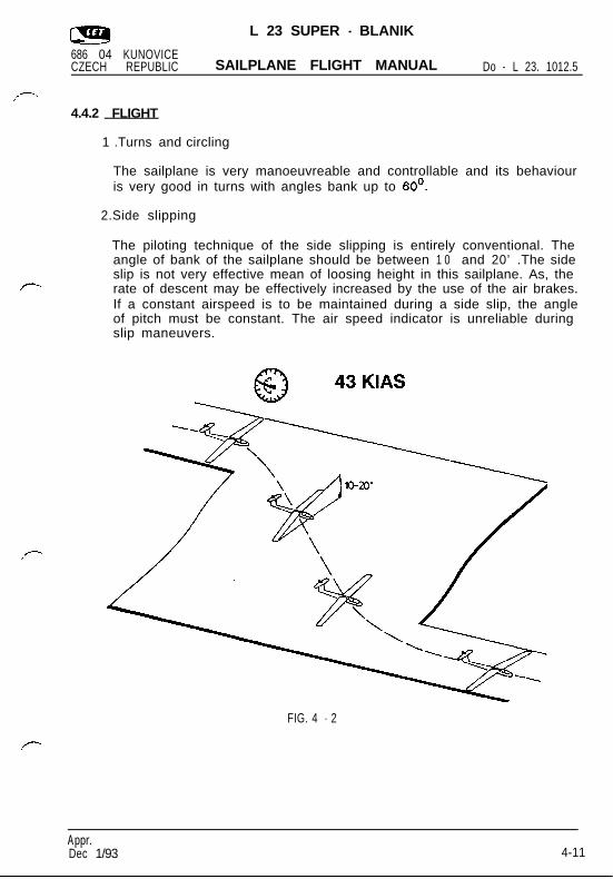
1 .Turns and circling
The sailplane is very manoeuvreable and controllable and its behaviouris very good in turns with angles bank up to 60’.
2.Side slipping
The piloting technique of the side slipping is entirely conventional. Theangle of bank of the sailplane should be between 1 0 and 20’ .The sideslip is not very effective mean of loosing height in this sailplane. As, therate of descent may be effectively increased by the use of the air brakes.If a constant airspeed is to be maintained during a side slip, the angleof pitch must be constant. The air speed indicator is unreliable duringslip maneuvers.
FIG. 4 - 2
Appr.Dec 1/93 4 - 4-11

L 23 SUPER - BLANIK
686 04 KUNOVICECZECH REPUBLIC SAILPLANE FLIGHT MANUAL Do - L 23. 1012.5
3.Stalls
Slow and continuous pulling aft on the control stick causes the sailplaneto stall. Ailerons and rudder should be used to control bank,if any.Pre-stall warning starts (at the speed of about 5% higher than the stallingspeed), in the form of buffeting of the rudder pedals and of all frontfuselage section. When stalled, the sailplane settles with a gentlepitching. Move the control stick forward and start the stall recovery.
CAUTION: Before stalling and spinning the following proceduresmust be done:
Trim: neutral
Air brakes: retracted and secured
Cockpit canopy locked and secured
Ventilation shut
Rudder pedals: properly adjusted to allow fulldeflections
Safety belts: fastened and tight
Loose objects: removed or secured
4.High Altitude Flight
Operation above 13,780 feet has not been demonstrated by themanufacturer. A sailplane placard provides calculated maximum ( WE )airspeeds above a pressure altitude of 13,780 feet for information only.High altitude flight should be conducted in accordance with anyapplicable operating rules.
Appr.D e c 1/93 4-12

L 23 SUPER - BLANIK .
686 04 KUNOVICECZECH REPUBLIC SAILPLANE FLIGHT MANUAL Do - L 23. 1012.5
4.4.3 APPROACH
The following approach speeds are recommended.
Descent Air brakes Approach speedsApproach speeds
Norma l retracted 41-46 KIAS41-46 KIAS
43-51 KIAS
51-60 KIAS51-60 KIAS
extended
Steeper ex tended
Anticipate mild sailplane ballooning when using higher approach speeds.
4.4.4 LANDING
Landing on the airport
The landing manoeuvre is entirely conventional. Use small elevator inputsat the flare. The sailplane should touch down with the landing gear firstand then with the tail wheel if landed correctly(to reduce shock to thetail wheel on ground contact). Do not flare prematurely in order to preventthe sailplane from droping from a higher height.
Off-field landing
It is recommended to land with the landing gear retracted if landing ona soft ground.
Note: In this case extend the wheel before the next flight.
Post flight
The following operations must be recorded in the sailplane log book asthey occur:
(1) Flight time with wing tip extensions installed.
(2) Number of winch and aerotow launches by type.
(3) Flight time during acrobatic maneuvers.
A p p r .Dec 1/93 4-13
L 23 SUPER - BLANIK
686 04 KUNOVICECZECH REPUBLIC SAILPLANE FLIGHT MANUAL Do - L 23. 1012.5
4.4.5 USE OF AIR BRAKES
It is recommended to use the air brakes in following cases :
1. To reduce landing especially roll on rough ground.
2. To increase accuracy of the landing manoeuvre.
Note: In case of using air brakes during landing, it is necessary tomaintain an approach speed of about 5 kts higher, because thestall speed with fully opened air brakes is about 3-4 kts higher.
3. To avoid exceeding the never exceed speed (vNE)during unusual atti-tude recoveries (for example during aerobatics).
It is recommended to use the air brakes in any case when the sailplanestarts to increase the speed and the pilot is uncertain of his orientationor how to manage the situation. Configuration with ‘I air brakesextended” will ensure that VNE is not exceeded.Use of air brakes willenhance the safety and makes handling easier because the extendedair brakes tend to stabilize the sailplane.The control lever should be held firmly when operating the air brakesto ensure smooth deployment and retraction.
A p p r .Dec 1/93 4-14

L 23 SUPER - BLANIK
686 04 KUNOVICECZECH REPUBLIC SAILPLANE FLIGHT MANUAL Do - L 23. 1012.5
4.4.6 BASIC AEROBATICS
The L 23 SUPER-BLANIK sailplane is able to perform the listed approvedaerobatic manoeuvres. The rate of acceleration of this sailplane is high,so great care must be taken not to exceed limitations given in Sections2.2, 2.6 and 2.7.Instruction guidelines for performing approved acrobatic manoeuvres are given on pages 13 to 19 of this Section.
WARNING: ONLY MANOEUVRES WITH POSITIVE G LOAD FACTORSARE APPROVED.
( Cont. )
Appr.Dec 1/93 4-15
L 23 SUPER - BLANIK
686 04 KUNOVICECZECH REPUBLIC SAILPLANE FLIGHT MANUAL Do - L 23. 1012.5
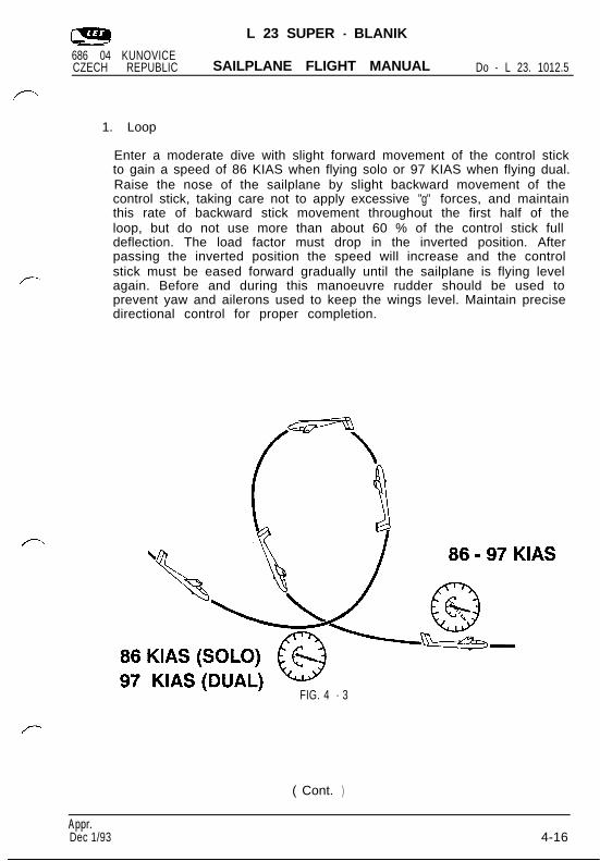
1. Loop
Enter a moderate dive with slight forward movement of the control stickto gain a speed of 86 KIAS when flying solo or 97 KIAS when flying dual.Raise the nose of the sailplane by slight backward movement of thecontrol stick, taking care not to apply excessive "g" forces, and maintainthis rate of backward stick movement throughout the first half of theloop, but do not use more than about 60 % of the control stick fulldeflection. The load factor must drop in the inverted position. Afterpassing the inverted position the speed will increase and the controlstick must be eased forward gradually until the sailplane is flying levelagain. Before and during this manoeuvre rudder should be used toprevent yaw and ailerons used to keep the wings level. Maintain precisedirectional control for proper completion.
FIG. 4 - 3
( Cont. )
Appr.Dec 1/93 3 4-16
L 23 SUPER - BLANIK
686 04 KUNOVICECZECH REPUBLIC SAILPLANE FLIGHT MANUAL Do - L 23. 1012.5
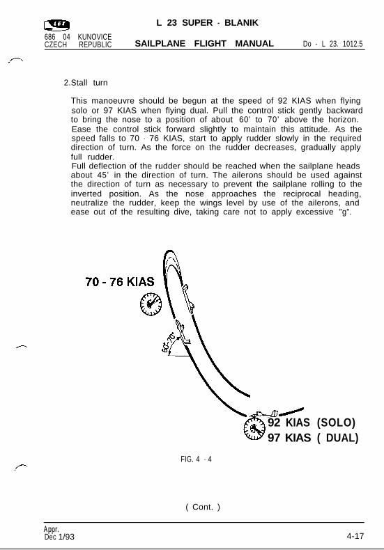
2.Stall turn
This manoeuvre should be begun at the speed of 92 KIAS when flyingsolo or 97 KIAS when flying dual. Pull the control stick gently backwardto bring the nose to a position of about 60’ to 70’ above the horizon.Ease the control stick forward slightly to maintain this attitude. As thespeed falls to 70 - 76 KIAS, start to apply rudder slowly in the requireddirection of turn. As the force on the rudder decreases, gradually applyfull rudder.Full deflection of the rudder should be reached when the sailplane headsabout 45’ in the direction of turn. The ailerons should be used againstthe direction of turn as necessary to prevent the sailplane rolling to theinverted position. As the nose approaches the reciprocal heading,neutralize the rudder, keep the wings level by use of the ailerons, andease out of the resulting dive, taking care not to apply excessive "g".
( Cont. )
92 KIAS (SOLO)97 KIAS ( DUAL)
FIG. 4 - 4
Appr.Dec 1/933 4-17
L 23 SUPER - BLANIK
686 04 KUNOVICECZECH REPUBLIC SAILPLANE FLIGHT MANUAL Do - L 23. 1012.5
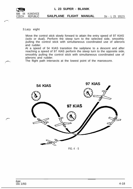
3.Lazy eight
Move the control stick slowly forward to attain the entry speed of 97 KIAS(solo or dual). Perform the steep turn to the selected side, smoothlypulling the control stick with simultaneous coordinated use of aileronsand rudder.At a speed of 54 KIAS transition the sailplane to a descent and afterreaching a speed of 97 KIAS perform the steep turn to the opposite side,smoothly pulling the control stick with simultaneous coordinated use ofailerons and rudder.The flight path intersects at the lowest point of the manoeuvre.
54 KIAS 97 KIAS
FIG. 4 - 5
Appr.Dec 1/933 4-18
L 23 SUPER - BLANIK
686 04 KUNOVICECZECH REPUBLIC SAILPLANE FLIGHT MANUAL Do - L 23. 1012.5
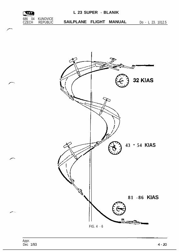
4.Spin
The sailplane performs the spin without any tendency to enter a flat spinat all operating centre of gravity positions. The sailplane has thetendency to recover from the spin by itself, when at the maximum flightweight and the forward centre of gravity. Entering the spin is entirelyconventional. Pull the control stick slowly back to approach the stall, usethe full deflection of the rudder at the stall speed of aproximately 32 KIAS(Fig. 4-3) and maintain full aft deflection of the control stick. Initiaterecovery from the spin by applying full opposite deflection of the rudder.When the sailplane stops the rotation, neutralize the rudder andsimultaneously ease the control stick forward. Recover the sailplanefrom the dive in the usual way. The attitude during the spin is 60’ to 70’nose down and the loss of height in one turn is aproximately 260 ft whenflying solo and 390 ft when flying dual. The time of one revolution of thespin is approximately 3.5 secs.
Caution: 1. Before spinning accomplish the procedures given inthe Flight Manual, Section 4, paragraph 3.
2. IAS error.The airspeed indications become erroneous at largeyaw angles, because the static vents on the sides of thefuselage are by-passed asymetrically.
3. When the spin is performed as an aerobatic manoeuvre,it is possible to maintain the spin by applying aileronin the direction of the rotation.Stop the spin rotation by applying full opposite rudderand neutralize the ailerons. When the sailplane stopsthe rotation, neutralize the rudder and ease the controlstick forward. Pull-out from the dive using standardprocedure.
Note: Airspeed indications well above the stall speed during a spinmay indicate a spiral dive rather than a spin.
( Cont. )
Appr.Dec 1/93 4-19
L 23 SUPER - BLANIK
686 04 KUNOVICECZECH REPUBLIC SAILPLANE FLIGHT MANUAL Do - L 23. 1012.5
43 - 54 KIAS
81 - 86 KIAS
FIG. 4 - 6
Appr.Dec 1/93
L 23 SUPER - BLANIK
686 04 KUNOVICECZECH REPUBLIC SAILPLANE FLIGHT MANUAL Do - L 23. 1012.5
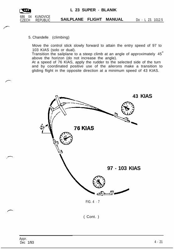
5. Chandelle (climbing)
Move the control stick slowly forward to attain the entry speed of 97 to103 KIAS (solo or dual).Transition the sailplane to a steep climb at an angle of approximately 45
o
above the horizon (do not increase the angle).At a speed of 76 KIAS, apply the rudder to the selected side of the turnand by coordinated positive use of the ailerons make a transition togliding flight in the opposite direction at a minimum speed of 43 KIAS.
43 KIAS
97 - 103 KIAS
FIG. 4 - 7
( Cont. )
Appr.Dec 1/93 4 - 21
L 23 SUPER - BLANIK
686 04 KUNOVICECZECH REPUBLIC SAILPLANE FLIGHT MANUAL Do - L 23. 1012.5
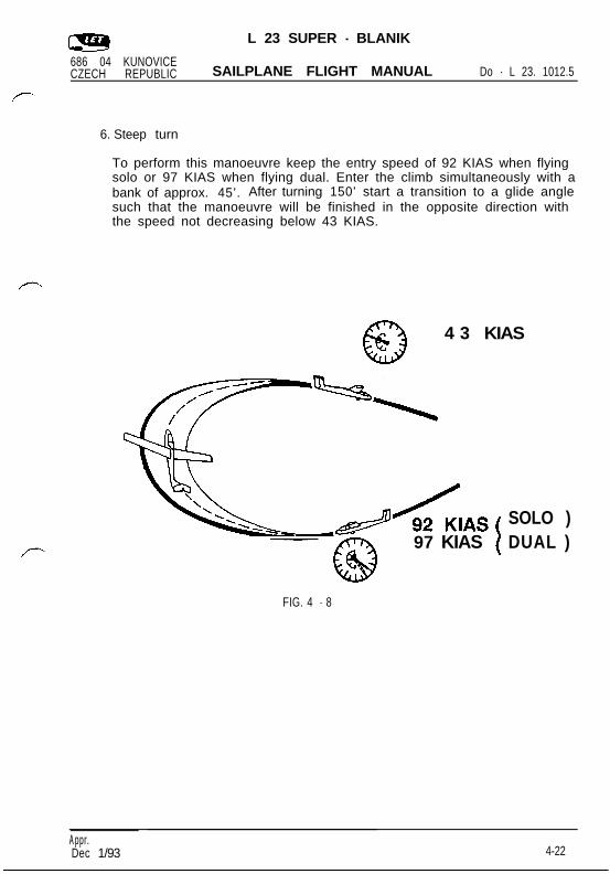
6. Steep turn
To perform this manoeuvre keep the entry speed of 92 KIAS when flyingsolo or 97 KIAS when flying dual. Enter the climb simultaneously with abank of approx. 45’. After turning 150’ start a transition to a glide anglesuch that the manoeuvre will be finished in the opposite direction withthe speed not decreasing below 43 KIAS.
@
4 3 KIAS
@
97 KIAS
FIG. 4 - 8
SOLO )DUAL )
Appr .Dec 1/93 4-22

L 23 SUPER - BLANIK686 04 K U N O V I C ECZECH REPUBLIC SAILPLANE FLIGHT MANUAL Do - L 23. 1012.5
SECTION 5
Performance
CONTENTS
5 . 1 Introduction
5 . 2 Approved data
5.2.1 Airspeed system calibration
5.2.2 Stall speeds
5 . 3 Additional information
5 . 3 . 1 Flight polar
A p p r .Dec 1/93 5 - 1

L 23 SUPER - BLANIK686 04 KUNOVICECZECH REPUBLIC SAILPLANE FLIGHT MANUAL Do - L 23. 1012.5
Section 5 provides approved data for airspeed calibration and stallspeeds. Other non-approved information is provided.
5 . 2 APPROVED DATA
5.2.1 AIRSPEED INDICATOR SYSTEM CALIBRATION,( Assumes zero instrument error )
The diagram is effective for maximum flight weight of 1124 lb.
8 0
6 0
f/
//
20 4 0 6 0 8 0 1 0 0 120 140Indicated Airspeed - KIAS
FIG. 5 - 1
Appr.Dec 1/93 5-2
L 23 SUPER - BLANIK686 04 KUNOVICECZECH REPUBLIC SAILPLANE FLIGHT MANUAL Do - L 23. 1012.5
.
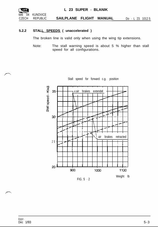
5.2.2 STALL SPEEDS ( unaccelerated )
The broken line is valid only when using the wing tip extensions.
Note: The stall warning speed is about 5 % higher than stallspeed for all configurations.
Stall speed for forward c.g. position
2 5
air brakes extendedJ--u--L
I A’/- air brakes retracted
FIG. 5 - 2Weight lb
A p p r .Dec 1/93 5-3
L 23 SUPER - BLANIK686 04 KUNOVICECZECH REPUBLIC SAILPLANE FLIGHT MANUAL Do - L 23. 1012.5
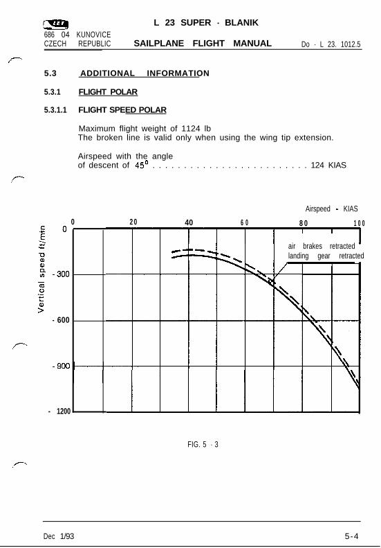
5.3 ADDITIONAL INFORMATION
5.3.1 FLIGHT POLAR
5.3.1.1 FLIGHT SPEED POLAR
Maximum flight weight of 1124 lbThe broken line is valid only when using the wing tip extension.
Airspeed with the angleof descent of 45’ . . . . . . . . . . . . . . . . . . . . . . . . . 124 KIAS
0 2 0 40 6 0 8 0 1 0 0
- 600
- 1200
Airspeed - KIAS
air brakes retractedlanding gear retracted
FIG. 5 - 3
Dec 1/93 5-4
686 04 KUNOVICECZECH REPUBLIC
L 23 SUPER - BLANIK
SAILPLANE FLIGHT MANUAL Do - L 23. 1012.5
SECTION 6
Weight and balance
C O N T E N T S
6.1 Introduction
6.2 Weight and balance record
6.3 Basic empty weight and moment
6.4 Balance chart
6.5 Balance record
6.6 Equipment list
Dec 1/93 6 - 1
L 23 SUPER - BLANIK686 04 KUNOVICECZECH REPUBLIC SAILPLANE FLIGHT MANUAL Do - L 23. 1012.5
6 . 1 INTRODUCTION
Section 6 includes basic empty weight and moment of the sailplane withstandard equipment and the equipment list (standard and optionalequipment). Procedures for determining the weight and centre of gravityposition are explained by an example calculation.
6.2 WEIGHT AND BALANCE RECORD
Weight and balance record providing information for calculating centre ofgravity position is given in the Maintenance Manual of the L 23 SUPER -BLANIK Sailplane, chapter 8.
6.3 BASIC EMPTY WEIGHT AND MOMENT
Basic empty weight . . . . . . . . . . . . . . . . . . . . . 683 lb t 2%(with the installed wing tip extensions) . . . . . . . . . 695 lb t 2%
Moment to the reference plane . . . . . . . . . . . . . . 17,923.1 in-lb
(see weight and balance record).
The reference datum is located 93.6 in aft of the sailplane nose.
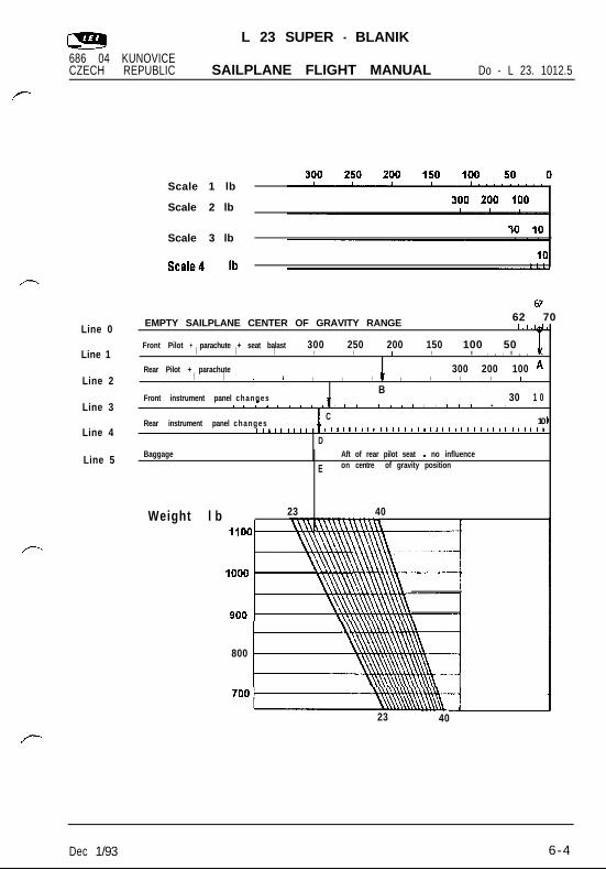
6.4 BALANCE CHART (FIG. 6-1)
1. Balance chart description
The varying load scales are in the upper part of the page. The separatescales are plotted in the middle part of the page. The chart of thecentre-of-gravity position vs. sailplane weight is given in the bottom partof the page. The region of the allowable centre of gravity range is theslanted shape in the chart and it refers to all flight conditions.
( Cont. )
Dec 1/93 6-2

L 23 SUPER - BLANIK686 04 KUNOVICECZECH REPUBLIC SAILPLANE FLIGHT MANUAL Do - L 23. 1012.5
2.Directions for the balance chart use
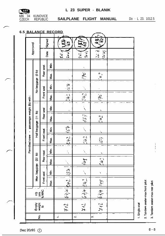
See FIG.6-1 on Page 6-4, Line 0..
. Make a dot on the Empty Sai lplane Center of Gravity Rangecorresponding with the value shown on the Balance Record on page6 - 5. When the wing tip extensions are used, move the center of gravityof the empty sailplane 1% MAC in aft direction. Draw a vertical downto Line 1. The intersection of the vertical and Line 1 is Point A.
- Next, use Scale 1 at the top of the chart. Measure the distance from 0on that scale to a number corresponding with the weight of the frontpilot + parachute + ballast seat (if used). Transfer this distance fromPoint A to the left, draw a vertical, and mark the intersection with Line2 as Point B.
- Next, use Scale 2. Measure the distance from 0 on that scale to anumber corresponding with the weight of the rear pilot + parachute.Transfer this distance from Point B to the left, draw a vertical, and markthe intersection with Line 3 as Point C.
- Next, use Scale 3 for any changes in the front instrument panel.Measure the distance from 0 on that scale to a number correspondingwith the weight of any instrument added or removed. Transfer thisdistance from Point C to the left (if an instrument is added), to the right(if removed). Draw a vertical, and mark the intersection with Line 4 asPoint D.
- Next, use Scale 4 for any changes in the rear instrument panel in thesame fashion as in the previous paragraph. That is how you arrive atpoint E. Draw a vertical on down to the lower part of the chart.
- Now, use the weight scale on the lower left part of the balance chart.Mark the sum of all weights: Empty sailplane + front pilot + parachute+ ballast seat + rear pilot + parachute + instrument changes +baggage.
- Draw a horizontal line from the mark to the right. The center of gravityposition is at the intersection of this horizontal line with the verticalfrom Point E.
- If this intersection is inside the slanted shape, the glider is loadedcorrectly. If the intersection is outside, the glider has to be reloaded.
Note: The baggage weight is to include any battery, oxygenbottle, water bottle etc.Items in the baggage compartmenthave no influence on the centre of gravity position, but theymust be included to the sum of all the weights.
Dec 1/93 6-3
L 23 SUPER - BLANIK686 04 KUNOVICECZECH REPUBLIC SAILPLANE FLIGHT MANUAL Do - L 23. 1012.5
Scale 1 lb
Scale 2 lb
Scale 3 lb
Line 0
Line 1
Line 2
Line 3
Line 4
Line 5
Front Pilot + parachute + seat balast 300 250 200 150I I I I I I I100 50 c
I I . , . I , , a ..
Rear Pilot + parachute 300 200 100 *I I I I I I I I I I I 1
BFront instrument panel changes 30 1 0. 1 1 1 I 1 1 I , . 1 I I 1 . . a I A
CRear instrument panel changes 10
11111111111111111111llllllllllllllllll
D
Weight l b 23 40I
800
Baggage c Aft of rear pilot seat - no influence
E on centre of gravity position
EMPTY SAILPLANE CENTER OF GRAVITY RANGE 62 701.1.
1
23 40
Dec 1/93 6-4
L 23 SUPER - BLANIK
686 04 KUNOVICECZECH REPUBLIC SAILPLANE FLIGHT MANUAL Do - L 23. 1012.5
6.5 BALANCE RECORD
L 23 SUPER - BLANIK
P
( Cont. )
686 04 KUNOVICECZECH REPUBLIC SAILPLANE FLIGHT MANUAL Do - L 23. 1012.5
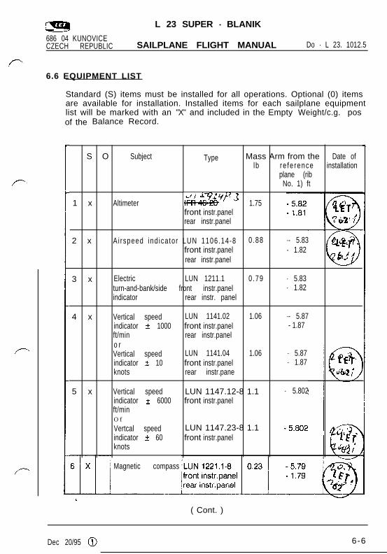
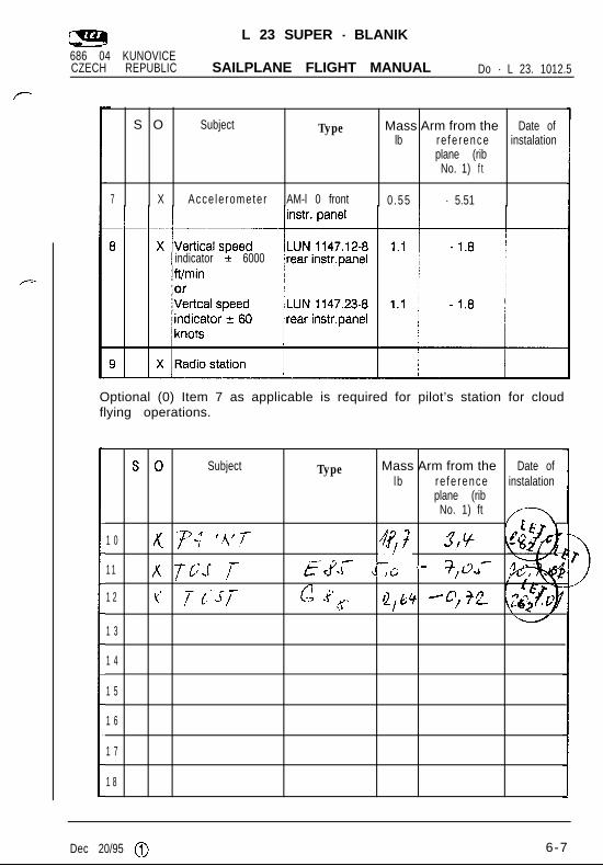
6.6 EQUIPMENT LIST
Standard (S) items must be installed for all operations. Optional (0) itemsare available for installation. Installed items for each sailplane equipmentlist will be marked with an "X" and included in the Empty Weight/c.g. posof the Balance Record.
S O Subject Type Mass Arm from the Date oflb re fe rence installation
plane (ribNo. 1) ft
1 x Altimetermyp-3
1.75front instr.panelrear instr.panel
2 x Ai rspeed ind ica tor LUN 1106.14-8 0 .88 -- 5.83front instr.panel - 1.82 *
Q
mhi’t -
rear instr.panel/ ib2,I
3 x Electric LUN 1211.1 0 .79 - 5.83turn-and-bank/side front instr.panel - 1.82indicator rear instr. panel
4 x Vertical speed LUN 1141.02 1.06 -- 5.87indicator t 1000 front instr.panel - 1.87ft/min rear instr.panelo rVertical speed LUN 1141.04 1.06 - 5.87indicator t 10 front instr.panel - 1.87knots rear instr.pane
5 x Vertical speed LUN 1147.12-8 1.1 - 5.802indicator t 6000 front instr.panelft/minO f
Vertcal speed LUN 1147.23-8 1.1indicator t 60 front instr.panelknots
Magnetic compass
Dec 20/95 @ 6-6
L 23 SUPER - BLANIK686 04 KUNOVICECZECH REPUBLIC SAILPLANE FLIGHT MANUAL Do - L 23. 1012.5
S O Subject Type Mass Arm from the Date oflb re fe rence instalation
plane (ribNo. 1) f t
7 X Acce le rometer AM-l 0 front 0 .55 - 5.51
indicator k 6000
Optional (0) Item 7 as applicable is required for pilot’s station for cloudflying operations.
s 0 Subject Type Mass Arm from the Date oflb re fe rence instalation
plane (ribNo. 1) ft y--y
P
1 0 x Fjl?N; ‘/(IT- 3,Y1 1 K 7C.f /- z;cj;;c J-G ‘- +y-1 2 Kf 7 (J-j- c -: .e -3.?g Qjb+ 4) jq
1 3
1 4
1 5
1 6
1 7
1 8
Dec 20/95 @ 6-7
L 23 SUPER - BLANIK
686 04 KUNOVICECZECH REPUBLIC SAILPLANE FLIGHT MANUAL Do - L23. 1012.5
SECTION 7
Sailplane and systems description
CONTENTS
7.1 Introduction
7.2 Sailplane description
7.3 Front seat ballast
7.4.1 Front cockpit - standard
7.4.2 Front cockpit - optional
7.5 Rear cockpit
Sep 20/96 0 7-l

L 23 SUPER - BLANIK
686 04 KUNOVICECZECH REPUBLIC SAILPLANE FLIGHT MANUAL Do - L23. 1012.5
7.1 INTRODUCTION
The description and operation of the sailplane and its systems are given in theMaintenance Manual of the L 23 SUPER - BLANIK Sailplane.
7.2 SAILPLANE DESCRIPTION
The L 23 SUPER BLANIK- sailplane is a cantilever, high-wing, two-seat gliderof all-metal structure. The rudder, elevator and ailerons are fabric covered. Inthe forward section part of the fuselage there are front and rear cockpits. Bothcockpits are covered with a two-part canopy which can be jettisoned in flight.Both cockpits are equipped with all sailplane flight control including flight andnavigation instrument panels. The sailplane is equipped with tow hooks eitherfor winch or aero-tow take-off.Wings including ailerons and air brakes, are attached to the fuselage at sixsuspension points (three on each side.There is a possibilityof using the wingtip extensions which enlarge the wing span from the 81st series. They may beconnected to the standard wing instead of the laminated wing tips. The verticalstabilizer is permanently fixed to the rear fuselage section. The horizontalstabilizer is fastened by hinges on the top of the vertical stabilizer.Elevator and aileron controls are actuated by control push rods and controlcables, the rudder control is pedal- operated also by control push rods andcontrol cables. Air brakes are controlled by control levers. The elevator trimtab is controlled by the control lever.The sailplane is equipped with the main landing gear and the tail landinggear. The main landing gear is mechanically semi-retractable with anoleo-pneumatic shock-absorber and a mechanical brake. The tail landing gearis equipped with a wheel and shock-absorber . Cockpits are ventilated by coldair tapped from the nose part of the fuselage. The baggage compartment isbehind the rear cockpit. Both cockpits are upholstered.
7.3 Front Seat Ballast
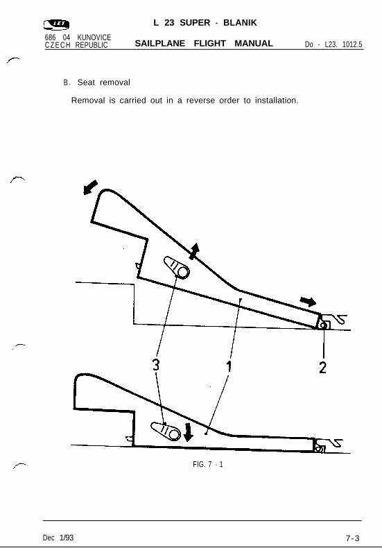
A.Seat installation, Fig. 7-1
Disassemble and remove the seat from the front cockpit.
Put the seat with ballast into the free space and insert stirrups (pos.2) in the rear part of the seat into the chamber on the rest suspender.
Move the levers on the seat sides upwards (pawls will shift in the seatface) and fold the seat (pos. 1) to the floor.
Move the levers downwards, the pawls will shift out and they mustshift in the hole on the floor frame (if the pawls do not shift in theholes, move the seat to both sides to enable shifting the pawls in theholes).
Dec 1/93 7-2
L 23 SUPER - BLANIK
686 04 KUNOVICEC Z E C H REPUBLIC SAILPLANE FLIGHT MANUAL Do - L23. 1012.5
B . Seat removal
Removal is carried out in a reverse order to installation.
FIG. 7 - 1
Dec 1/93 7-3
L 23 SUPER - BLANIK
686 04 KUNOVICECZECH REPUBLIC SAILPLANE FLIGHT MANUAL Do - L23. 1012.5
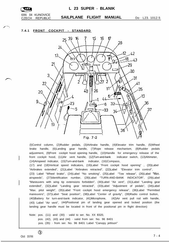
7.4.1 FRONT COCKPIT - STANDARD
I
I
(l)Control column, (2)Rudder pedals, (3)Airbrake handle, (4)Elevator trim handle, (5)Wheelbrake handle, (6)Landing gear handle, (7)Rope release mechanism, (8)Rudder pedals
adjustment, (9)Front cockpit hood opening handle, (10)Handle for emergency release of thefront cockpit hood, (11)Air vent handle, (12)Turn-and-bank indicator switch, (13)Altimeter,
(14)Airspeed indicator, (15)Turn-and-bank indicator, (16)Compass,(17) and (18)Vertical speed indicators, (19)Label “Front cockpit hood opening” , (20)Label
“Airbrakes extended”, (21)Label “Airbrakes retracted”, (22)Label “Elevator trim control”,
(23) Label “Wheel brake”, (24)Label “No smoking”, (25)Label “Tow release”, (26)Label “Max.airspeeds”, (27)ldentification number, (28)Label “TURN-AND-BANK INDICATOR”, (29)Label
“Maneuvers with wing tip extensions forbidden”, (30)Label “Air vent”, (31)Label “Landing gearextended”, (32)Label “Landing gear retracted”, (33)Label “Adjustment of pedals”, (34)Label
“Max. pilot weight”, (35)Label “Front cockpit hood emergency release”, (36)Label “Permittedmaneuvers”, (37)Label “Seat position”, (38)Label “Center of gravity”, (39)Radio control button,
(40)Battery for turn-and-bank indicator, (41)Microphone, (42)Air vent pull rod with handle,
(43) Label “Air vent”, (44)Positional pin of landing gear opened and locked position (the
landing gear handle must be located in front of the positional pin in flight direction)
Note: pos. (11) and (30) - valid to ser. No. XX 8320,
pos. (42), (43) and (44) - valid from ser. No. 96 8401pos. (35) - from ser. No. 96 8401 Label “Canopy jettison”
0Oct 30/96 7 - 4
L 23 SUPER - BLANIK
686 04 KUNOVICECZECH REPUBLIC SAILPLANE FLIGHT MANUAL Do - L23. 1012.5
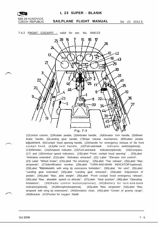
7.4.2 FRONT COCKPIT - valid for ser. No. 948123
(1)Control column, (2)Rudder pedals, (3)Airbrake handle, (4)Elevator trim handle, (5)Wheelbrake handle, (6)Landing gear handle, (7)Rope release mechanism, (8)Rudder pedalsadjustment, (9)Cockpit hood opening handle, (10)Handle for emergency release of the frontcockp i t hood , (11)Air ven t hand le , (12)Turn-and-bank ind ica to r switch(optional),(13)Altimeter, (14)Airspeed indicator, (15)Turn-and-bank indicator(optional), (16)Compass.(17) and (18)VerticaI speed indicators, (19)Label “Front cockpit hood opening” , (20)Label“Airbrakes extended”, (21)Label “Airbrakes retracted”, (22) Label “Elevator trim control”.(23) Label “Wheel brake”, (24)Label “No smoking”, (25)Label “Tow release”, (26)Label “Max.airspeeds”, (27)Identlfication number, (28)Label “TURN-AND-BANK INDICATOR”(optionaI),(29)Label "Manoeuvers with wing tip extensions forbidden”, (30)Label “Air vent”, (3l)Label“Landing gear extended”, (32)Label “Landing gear retracted”, (33)Label “Adjustment ofpedals”, (34)Label “Max. pilot weight”, (35)Label “Front cockpit hood emergency release”,(36)Label “Max. alowable speed vs altitude”, (37)Label “Seat position”, (38)Label “Operatinglimitations”, (39)Radio con t ro l bu t ton (op t iona I ) , (40 )Ba t te ry fo r tu rn -and-bankindicator(optional), (41)Microphone(optional), (42)Label "Max. airspeeds”, (43)Label “Max.airspeed with wing tip extensions”, (44)Deviation chart, (45)Label “Center of gravity range”,(46)Bracket. (47)Pocket for oxygen mask
Oct 30/966 7 - 5
L 23 SUPER - BLANIK
686 04 KUNOVICECZECH REPUBLIC SAILPLANE FLIGHT MANUAL Do - L23. 1 0 1 2 . 5
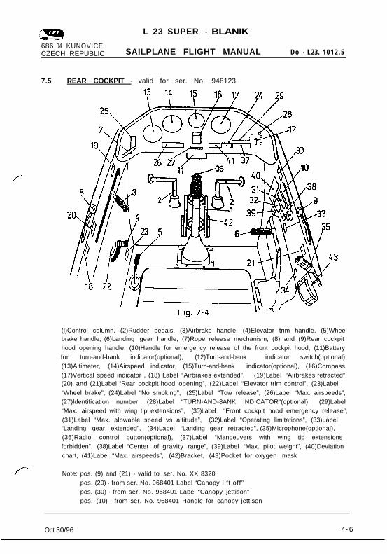
7.5 REAR COCKPIT - valid for ser. No. 948123
(l)Control column, (2)Rudder pedals, (3)Airbrake handle, (4)Elevator trim handle, (5)Wheelbrake handle, (6)Landing gear handle, (7)Rope release mechanism, (8) and (9)Rear cockpithood opening handle, (10)Handle for emergency release of the front cockpit hood, (11)Batteryfor turn-and-bank indicator(optional), (12)Turn-and-bank indicator switch(optional),(13)Altimeter, (14)Airspeed indicator, (15)Turn-and-bank indicator(optional), (16)Compass.(17)Vertical speed indicator , (18) Label “Airbrakes extended”, (19)Label “Airbrakes retracted”,(20) and (21)Label “Rear cockpit hood opening”, (22)Label “Elevator trim control”, (23)Label“Wheel brake”, (24)Label “No smoking”, (25)Label “Tow release”, (26)Label “Max. airspeeds”,(27)ldentification number, (28)Label “TURN-AND-8ANK INDICATOR”(optional), (29)Label“Max. airspeed with wing tip extensions”, (30)Label “Front cockpit hood emergency release”,(31)Label “Max. alowable speed vs altitude”, (32)Label “Operating limitations”, (33)Label“Landing gear extended”, (34)Label “Landing gear retracted”, (35)Microphone(optional), 1(36)Radio control button(optional), (37)Label “Manoeuvers with wing tip extensionsforbidden”, (38)Label “Center of gravity range”, (39)Label “Max. pilot weight”, (40)Deviationchart, (41)Label “Max. airspeeds”, (42)Bracket, (43)Pocket for oxygen mask
Note: pos. (9) and (21) - valid to ser. No. XX 8320pos. (20) - from ser. No. 968401 Label “Canopy l i f t off”pos. (30) - from ser. No. 968401 Label “Canopy jettison”pos. (10) - from ser. No. 968401 Handle for canopy jettison
Oct 30/966 7 - 6
L 23 SUPER BLANIK
686 04 KUNOVICECZECH REPUBLIC SAILPLANE FLIGHT MANUAL Do - L 23. 1012.5
SECTION 8
Sailplane handling, care and maintenance
CONTENTS
8.1 Introduction
8.2 Sailplane inspection period
Dec 1/93 8 - 1
L 23 SUPER BLANIK
686 04 KUNOVICECZECH REPUBLIC SAILPLANE FLIGHT MANUAL Do - L 23. 1012.5
8 . 1 INTRODUCTION
Procedures recommended by the manufacturer for proper groundhandling, servicing and maintenance, which must be followed if thesailplane is to retain new-plane performance and dependability,aregiven in the Maintenance Manual of the L 23 SUPER - BLANIK Sailplane.
8.2 SAILPLANE INSPECTION PERIOD
Maintenance and servicing of the sailplane are provided in the L 23SUPER-BLANIK sailplane Maintenance Manual Do - L 23 1031.3 ( seeSection 5 ).
Dec 1/93 8-2
L 23 SUPER - BLANIK
686 04 KUNOVICECZECH REPUBLIC SAILPLANE FLIGHT MANUAL Do - L 23. 1012.5
SECTION 9
Supplements
CONTENTS
9.1 Introduction
9.2 List of inserted Supplements
9.3 Supplements inserted
Jan 13/990
9-l
L 23 SUPER - BLANIK
686 04 KUNOVICECZECH REPUBLIC SAILPLANE FLIGHT MANUAL Do - L 23. 1012.5
9.1 INTRODUCTION
Section 9 of thisinformation for optionaland additionaly itsailplane operation
Sailplane Flight Manual provides supplemental equipment which is installed on the sailplane
may contain the supplementary information on
The information contained in this document supplements or supersedsthe basic Sailplane Flight Manual where covered in the sectionscontained herein. For limitations, procedures and performance notcontained in this supplement, consult the basic Sailplane Flight Manual.
92. LIST OF INSERTED SUPPLEMENTS ’
Title of inserted supplement
I Jan 13/99 0 9-2
L 23 SUPER - BLANIK
686 04 KUNOVICECZECH REPUBLIC SAILPLANE FLIGHT MANUAL Do - L 23. 1012.5
Date of Doc. No. Title of inserted supplementinsertion
I Jan 13/990
9-3