Embed Size (px)
Citation preview
The objective of this paper is to bring forth thebenefits that can be realized by using LSI micro-processors in test equipment and instrument appli-cations. We will attempt to do this by describingthe Qualifier* 901, which is a low-cost bench topdigital integrated circuit tester controlled by anLSI microprocessor. First, we identify the scope oflow-cost testers and describe the general principlesof operation of such testers using fixed logiccontrol. Then we describe the Qualifier 901, andfinally, we point out the advantages gained by theusage of the intelligence of the microprocessor inQualifier 901 versus fixed logic controlled testers.*Trademark, Fairchild Camera and Instrument Corporation.
T. A. Laliotis, T. D.' BrumettFairchild Camera and Instrument Corporation
Introduction
Low-cost digital integrated circuit testers have tradi-tionally been used primarily by digital IC users at theirincoming inspection facilities in order to screen outmalfunctioning devices before assembling them into theirsystem or subsystem. The cost of identifying and replacingbad devices at the subsystem or the system level is very highcompared to eliminating them at the incoming inspectionstage.
The terms "low-cost tester" or "bench top tester" hereimply a portable instrument that is physically small enoughto be located on a laboratory bench and costs in the rangeof $10,000. Such general-purpose testers are limited to DCparametric and functional tests. Dynamic (AC) parametrictests such as propagation delays and transient responses areleft to the more expensive large testers.
However, due to the way that integrated circuits arefabricated, their AC parameters are very similar amongdevices that have been fabricated using the same process,same environmental conditions, and the same supply of rawmaterials. Thus, it is not uncommon for devicemanufacturers to perform only sample testing of ACparameters at the wafer or die stage for each production lotrather than testing 100% of the lot. Therefore, dependingupon their accuracy and thoroughness of DC parametricand functional testing capabilities, low-cost testers could beused also by IC manufacturers at their final quality*Portions of this paper were first presented and published at the1975 International Microelectronics Conference.
60
assurance inspection facilities before shipping the devices totheir customers. The low cost of such testers would permitmultiple units to be employed on-site by both users andmanufacturers of devices in order to handle large volumesof device testing.
Fixed Logic Controlled Testers
Figure 1 shows the basic building blocks of a tester. Theinterconnection matrix is used to connect the pins of theDUT and FRD to the forcing functions and to thecomparators.
The FRD is a known good device of the same type as theDUT. It receives the same input pattern as the DUT, and itsfunction is to provide a reference for comparing theoutputs of the DUT to decide if the DUT meets itsfunctional specification.
The DUT and FRD are always mounted on the sameprinted circuit board that constitutes the programmingboard. A separate programming board is required for eachdevice type to be tested.
The matrix is implemented differently by differentmanufacturers. Some have the matrix hardwired on theprogramming board, while others do it by push-buttonswitch matrix on the console of the tester. Theprogrammable parametric limits are entered manuallythrough switches at the front console.
The voltage and current supplies that drive the input andoutput pins of the DUT and FRD are programmed eitherby manual entry switches or by a separate programming
COMPUTER
L-1
Figure 1. Functional diagram for a general purpose, fixed logiccontrolled digital IC tester
MANUAL ENTRY SWITCHESAND TEST RESULT DISPLAY
--1
-.
N. N~~~~~~~~~~~~~1
FAMIL BOARDS
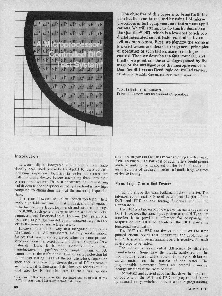
Figure 2. Physical configuration of a non-microprocessorcontrolled tester
board called the family board that contains high precisioncircuits for deriving those values, and it is used with alldevices in a particular family (TTL, DTL, ECL, etc).
The input pattern generator either consists of a fixedbinary pattern, such as a Gray code generator that generatesall possible binary combinations for the input pins, or it isselected through manual entry switches at the tester'sconsole. Patterns for combinatorial devices can be easily
October 1975
handled. However, sequential devices with clocked andenabling types of inputs require a lot more carefulconsideration in order to perform a thorough functionaltest because of the high comlexity of such necessary inputpatterns. This is one of the most important deficiencies ofthis type of tester that is not under microprocessor control.
Figure 2 shows a typical fixed logic controlled tester andthe necessary programming and family boards.
61
DIGITAL BUS(1 P.C. Motherboard)
ANALOG REFERENCE
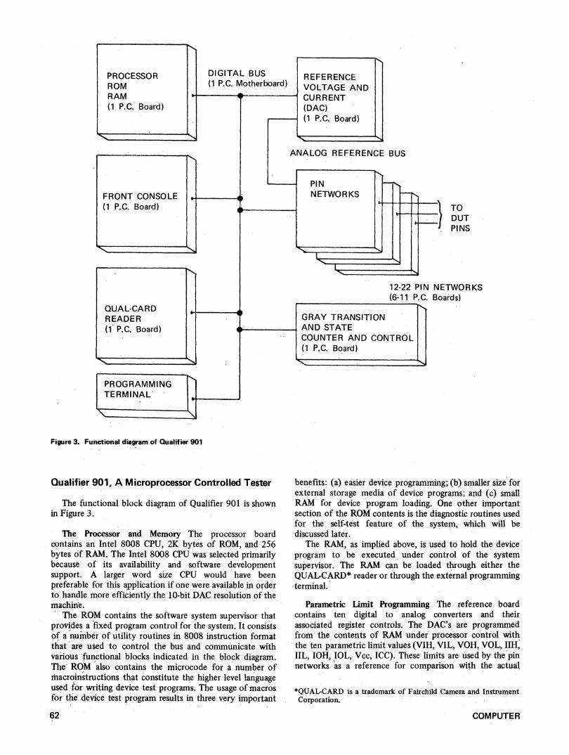
Figure 3. Functional diagram of Qualifier 901
Qualifier 901, A Microprocessor Controlled Tester
The functional block diagram of Qualifier 901 is shownin Figure 3.
The Processor and Memory The processor boardcontains an Intel 8008 CPU, 2K bytes of ROM, and 256bytes of. RAM. The Intel 8008 CPU was selected primarilybecause of its availability and 'software developmentsupport. A larger word size' CPU would 'have beenpreferable for this application if one were available in orderto handle more efficiently the 10-bit DAC resolution of themachine.
The ROM contains the software system supervisor thatprovides a fixed, program -control for the system. It consistsof a number of utility routines in 8008 instruction form'atthat are used to control the bus and communicate withvarious-functional blocks indicated in the block diagram.The' ROM also 'contains the microcode for a number ofmacroinstructions that constitute the higher level languageused for writing device test programs. The usage of macrosfor the device test program results -in three very important
62
benefits: (a) easier device programming; (b) smaller size forexternal storage media of device programs; and (c) smallRAM 'for device program loading. One other importantsection of the ROM contents is the diagnostic routines usedfor the self-test feature of the system, which will bediscussed later.
The RAM, as implied above, is used to hold the deviceprogram to be executed under control of the systemsupervisor. The RAM can be 'loaded through either theQUALCARD* reader or through the external programmingterminal.
Parametric Limit Programming The reference boardcontains ten digital to analog converters and theirassociated register controls. The DAC's' are programmedfrom- the contents of -RAM under' processor control withthe ten parametric limit values (VIH, VIL, VOH, VOL, IIH,IIL, IOH, IOL, Vcc, ICC). These limits are used by the pinnetworks as a reference for comparison with the actual
*QUAL-CARD is a trademark of Fairchild Camera and InstrumentCorporation.
COMPUTER
PROCESSORROMRAM(1 P.C. Board)
REFERENCEVOLTAGE ANDCURRENT(DAC)(1 P.C. Board)
FRONT CONSOLE(1 P.C. Board)
BUS
PINNETWOR KS
QUAL-CARDD .READER(1 P.C. Board)
I---
-4
TODUT-PINS
NETWORKSBoards)
GRAY TRANSITIONAND STATECOUNTER AND CONTROL(1 P.C. Board). -J-
PROGRAMMINGTERMINAL
x _ I~~~~~~~~~~~O.
_~~~~~~~I
12-22 PIN(6-11 P.C.
N
I-T
'11.
I
values obtained at the DUT pins. The great advantageoffered by the microprocessor control here is the fact thatthe total device program may consist of a number ofsubprograms, each of which uses its own set of limits. Thus,all conditional limits can be tested under the properconditions. This is a severe limitation of the fixed logiccontrolled testers, where the limits are manually entered orhardwired on the programming board and remainunchanged throughout the entire test. With the increasingdevice complexities and the profileration of the number ofsemiconductor device manufacturers, programmable limitflexibility is very important for achieving thorough tests.Furthermore, the automatic programmability eliminates thecumbersome and costly repetition that is inherent inprogramming boards or manual entries.
The Pin Networks The pin networks consist of thenecessary digital and analog electronics in order to providethe excitation and measurement circuits for each of theDUT signal pins. Note that the device Vcc pin and groundpin are not handled by pin networks. Ground is simply thevoltage reference, but Vcc is always a constant voltagesource power supply and requires higher current capabilitythan regular signal pins. Thus, the Vcc is treated separatelyon the reference board.
The analog section of the pin networks is controlled bythe contents of a digital register that, in turn, gets loadeddynamically during program execution from the contentsof RAM under processor control. Thus, each pin can beprogrammed dynamically during program execution to bean input, or an output, or an open. An analog signalcomparator is used to compare the DUT pin response withthe reference limits provided by the reference board. Theresults of the comparison are held in a register that isaccessible by the processor for analysis and display at theconsole.The dynamic programmability of pins is a very
important feature of the microprocessor controlled testerbecause it eliminates the costly and cumbersomeinterconnection matrix that is inherent in fixed logiccontrolled testers, and it provides great flexibility forthorough testing.
As an example of the gained flexibility, let us considerthe following:
During the functional test portion of a sequential deviceprogram, some of the input pins can be placed under Gray
count control to provide for all possible input states, andother pins can be placed under processor control. Graycounting takes place at a very rapid rate, whereas processorcontrol speed is limited by the cycle time of the processor.By placing clock pins and enable type of pins underprocessor control, it is possible, at any point in theprogram, to instruct a pin network to pulse positive orpulse negative for any number of predetermined times.Also, a pin network can be instructed to remain at the lowstate for a given number of Gray steps or to remain at thehigh state for a given number of steps. This type offlexibility is very important, especially in complex devices,in order to achieve thorough testing.
The Control Board This section of the tester containsthe basic clock generator for the whole system, the Graypattern generator that is dynamically loaded into the pinnetworks during test and the transition and state countersused for the functional part of the test. The function of thetransition and state counter is explained in a later sectionentitled "Functional Testing."
The Console The Qualifier 901 front console consistsof the QUAL-CARD reader that will be discussed in thenext section, the digital panel meter option, and theconsole board that contains all the indicators and switchesthat interface with the processor.
The QUAL-CARD Reader Device programs consist ofdevice statistics (such as the number of pins, identificationof power pins, etc.), tables of parametric values and limits,and a set of program steps in the form of macrocommandsto define the test sequence.
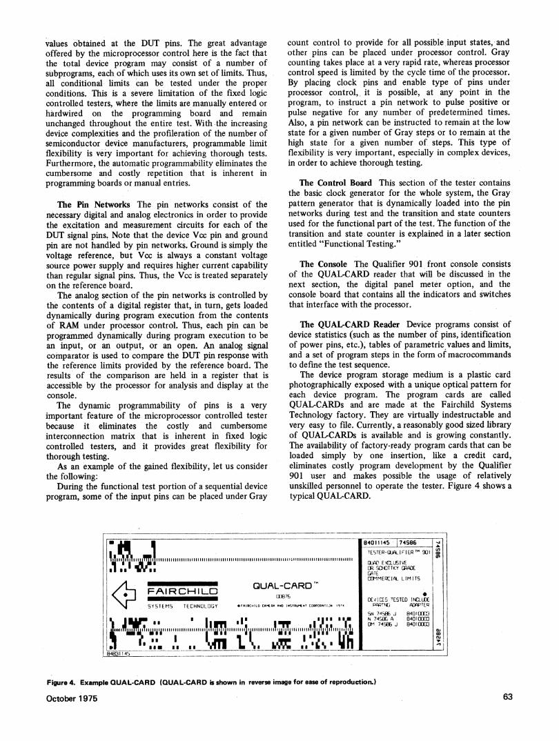
The device program storage medium is a plastic cardphotographically exposed with a unique optical pattem foreach device program. The program cards are calledQUAL-CARDs and are made at the Fairchild SystemsTechnology factory. They are virtually indestructable andvery easy to file. Currently, a reasonably good sized libraryof QUAL-CARDs is available and is growing constantly.The availability of factory-ready program cards that can beloaded simply by one insertion, like a credit card,eliminates costly program development by the Qualifier901 user and makes possible the usage of relativelyunskilled personnel to operate the tester. Figure 4 shows atypical QUAL-CARD.
684011145 174S86TESTEP-iqLALIERTF
Rt SDTTKY GRDPIEGATECEMMERCIAL LIMITS
FAIRCHILD QUAL-CARODEICE TESTED INCUDE(
SYSTEMS TECHNOLOGY OFAIRCHILD CAMEQA AND STAUMET COQPTQATIN 19A4 PAT~ ADAPTEP
SN 745a J 8401EXC3lI7 |~- "I IIjIllzl III .......lls liii*I,s,,,11g N 745-EPA 840100 3
lO 74S, B4010E003
631 1 5_
Figure 4. Example QUAL-CARD (QUAL-CARD is shown in reverse image for ease of reproduction.)
October 1975 63
The QUAL-CARD reader consists of an optical arraysensor that can read the 256 8-bit characters from theQUAL-CARD under processor control as the QUAL-CARDis manually slid through the sensor. The QUAL-CARDcontents are loaded into RAM. Additional codes on theQUAL-CARD provide redundancy check codes forvalidating a satisfactory program load.
User Programming Terminal
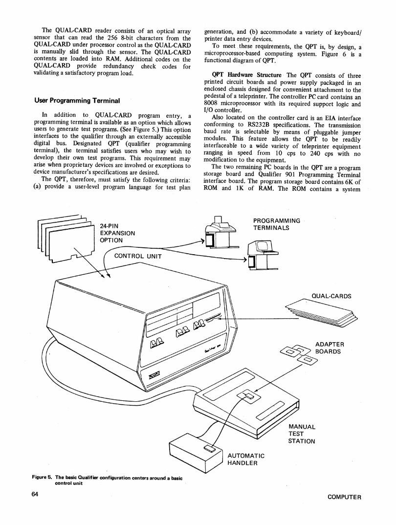
In addition to QUAL-CARD program entry, aprogramming terminal is available as an option which allowsusers to generate test programs. (See Figure 5.) This optioninterfaces to the qualifier through an externally accessibledigital bus. Designated QPT (qualifier programmingterminal), the terminal satisfies users who may wish todevelop their own test programs. This requirement mayarise when proprietary devices are involved or exceptions todevice manufacturer's specifications are desired.
The QPT, therefore, must satisfy the following criteria:(a) provide a user-level program language for test plan
24-PINEXPANSIONOPTION
generation, and (b) accommodate a variety of keyboard/printer data entry devices.
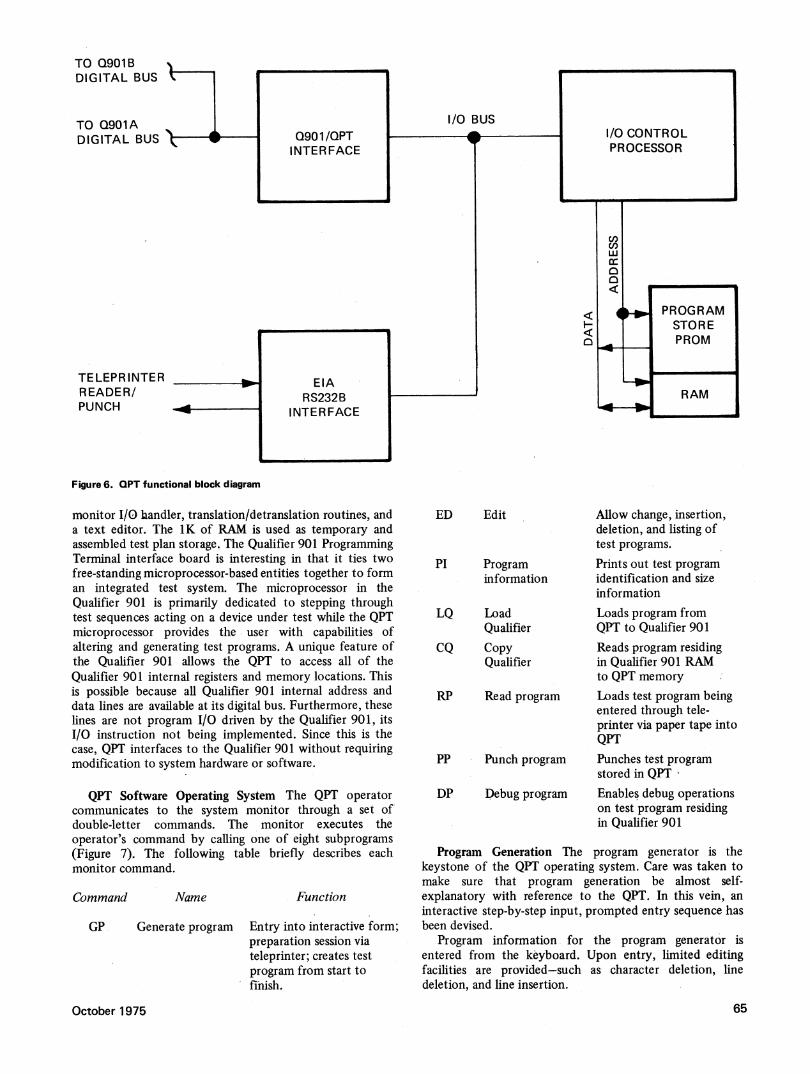
To meet these requirements, the QPT is, by design, amicroprocessor-based computing system. Figure 6 is afunctional diagram of QPT.
QPT Hardware Structure The QPT consists of threeprinted circuit boards and power supply packaged in anenclosed chassis designed for convenient attachment to thepedestal of a teleprinter. The controller PC card contains an8008 microprocessor with its required support logic andI/O controller.
Also located on the controller card is an EIA interfaceconforming to RS232B specifications. The transmissionbaud rate is selectable by means of pluggable jumpermodules. This feature allows the QPT to be readilyinterfaceable to a wide variety of teleprinter equipmentranging in speed from 10 cps to 240 cps with nomodification to the equipment.
The two remaining PC boards in the QPT are a programstorage board and Qualifier 901 Programming Terminalinterface board. The program storage board contains 6K ofROM and 1K of RAM. The ROM contains a system
PROGRAMMINGTERMI NALS
QUAL-CAR DS
MANUALTESTSTATION
AUTOMATICHANDLER
Figure 5. The basic Qualifier configuration centers around a basiccontrol unit
64 COMPUTER
TO Q901B sDIGITAL BUS
TO Q901ADIGITAL BUS
TELEPR INTERREADER/PUNCH
Figure 6. OPT functional block diagram
monitor I/O handler, translation/detranslation routines, anda text editor. The 1K of RAM is used as temporary andassembled test plan storage. The Qualifier 901 ProgrammingTerminal interface board is interesting in that it ties twofree-standing microprocessor-based entities together to forman integrated test system. The microprocessor in theQualifier 901 is primarily dedicated to stepping throughtest sequences acting on a device under test while the QPTmicroprocessor provides the user with capabilities ofaltering and generating test programs. A unique feature ofthe Qualifier 901 allows the QPT to access all of theQualifier 901 internal registers and memory locations. Thisis possible because all Qualifier 901 internal address anddata lines are available at its digital bus. Furthermore, theselines are not program I/O driven by the Qualifier 901, itsI/O instruction not being implemented. Since this is thecase, QPT interfaces to the Qualifier 901 without requiringmodification to system hardware or software.
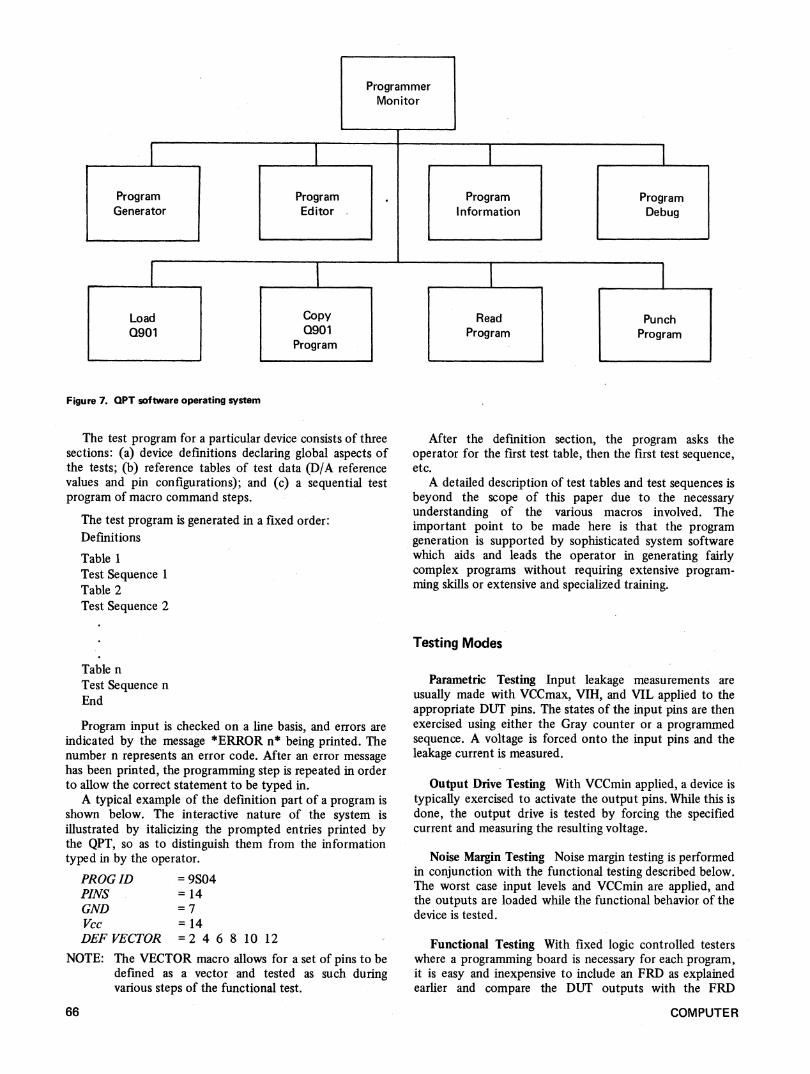
QPT Software Operating System The QPT operatorcommunicates to the system monitor through a set ofdouble-letter commands. The monitor executes theoperator's command by calling one of eight subprograms(Figure 7). The following table briefly describes eachmonitor command.
Command Name Function
GP Generate program Entry into interactive form;preparation session viateleprinter; creates testprogram from start tofinish.
October 1975
ED Edit
PI Programinformation
LQ LoadQualifier
CQ CopyQualifier
RP Read program
PP Punch program
DP Debug program
Allow change, insertion,deletion, and listing oftest programs.Prints out test programidentification and sizeinformationLoads program fromQPT to Qualifier 901Reads program residingin Qualifier 901 RAMto QPT memoryLoads test program beingentered through tele-printer via paper tape intoQPTPunches test programstored in QPT'Enables debug operationson test program residingin Qualifier 901
Program Generation The program generator is thekeystone of the QPT operating system. Care was taken tomake sure that program generation be almost self-explanatory with reference to the QPT. In this vein, aninteractive step-by-step input, prompted entry sequence hasbeen devised.
Program information for the program generator isentered from the keyboard. Upon entry, limited editingfacilities are provided-such as character deletion, linedeletion, and line insertion.
65
ProgrammerMonitor
Figure 7. QPT software operating system
The test program for a particular device consists of threesections: (a) device definitions declaring global aspects ofthe tests; (b) reference tables of test data (D/A referencevalues and pin configurations); and (c) a sequential testprogram of macro command steps.
The test program is generated in a fixed order:Definitions
Table 1Test Sequence 1Table 2Test Sequence 2
Table n
Test Sequence n
End
Program input is checked on a line basis, and errors areindicated by the message *ERROR n* being printed. Thenumber n represents an error code. After an error messagehas been printed, the programming step is repeated in orderto allow the correct statement to be typed in.A typical example of the definition part of a program is
shown below. The interactive nature of the system isillustrated by italicizing the prompted entries printed bythe QPT, so as to distinguish them from the informationtyped in by the operator.
PROG ID = 9S04PINS =14GND =7Vcc 14DEFVECTOR =2 4 6 8 10 12
NOTE: The VECTOR macro allows for a set of pins to bedefined as a vector and tested as such duringvarious steps of the functional test.
66
After the defimition section, the program asks theoperator for the first test table, then the first test sequence,etc.A detailed description of test tables and test sequences is
beyond the scope of this paper due to the necessaryunderstanding of the various macros involved. Theimportant point to be made here is that the programgeneration is supported by sophisticated system softwarewhich aids and leads the operator in generating fairlycomplex programs without requiring extensive program-ming skills or extensive and specialized training.
Testing Modes
Parametric Testing Input leakage measurements areusually made with VCCmax, VIH, and VIL applied to theappropriate DUTT pins. The states of the input pins are thenexercised using either the Gray counter or a programmedsequence. A voltage is forced onto the input pins and theleakage current is measured.
Output Drive Testing With VCCmin applied, a device istypically exercised to activate the output pins. While this isdone, the output drive is tested by forcing the specifiedcurrent and measuring the resulting voltage.
Noise Margin Testing Noise margin testing is performedin conjunction with the functional testing described below.The worst case input levels and VCCmin are applied, andthe outputs are loaded while the functional behavior of thedevice is tested.
Functional Testing With fixed logic controlled testerswhere a programming board is necessary for each program,it is easy and inexpensive to include an FRD as explainedearlier and compare the DUT outputs with the FRD
COMPUTER
ProgramGenerator
I ,-
ProgramEditor
ProgramI nformation
LoadQ901
ProgramDebug
CopyQ901
Program
ReadProgram
PunchProgram
1 I
I I
outputs for a complete functional test. With programmingboards eliminated in microcontrolled systems, anothermethod for functional testing must be found. One methodused by a few low-cost testers is to count the output signaltransitions while the inputs are being exercised. In mostcases, this method can be adequate; however, it can beproven that it is not 100% complete in certain cases. Amore reliable count can be obtained by counting not onlythe state transitions but also the time periods during whicha signal was in the high state. Even with this improvement,however, situations could be found where functional faultswere not detected by the count method.
Qualifier 901 uses a combination of state sensing andtransition counting; however, additional program state testscan be included by the programmer as he sees fit, in orderto achieve 100o functional testing.
Summary of Features Attributableto the Microprocessor
Tester Programming The fact that a microprocessor isavailable for loading a program in RAM is perhaps the mostsignificant benefit realized in the microprocessor-controlledtester. It eliminates the cumbersome and expensiveprogramming boards. Typically, programming boards cost$150-300. Thus, a user that buys a $5000 tester may endup spending another $15,000 if he has need for a library of50-100 programs, which is typical. Moreover, programmingboards are difficult to store because they are bulky andrequire maintenance. QUALCARDs cost only $55; theyare very easy to file and require no maintenance.
Also, the microprocessor-based controller makes theprogramming terminal adaptable to a wide class ofteleprinters, thus providing Qualifier 901 users with aninexpensive programming terminal. The interactive natureof the program generator and editor provides the user withthe capabilities of test program creation and modificationwithout encumbering him with the rigors of machine- orassembly-level programming.
Completeness of Testing The dynamic programmabilityof limits and parameters during the parametric tests and thecomplete flexibility under processor control for lOO10ofunctional testing make the microprocessor-controlledtester a much more accurate and useful instrument. This isextremely important, considering the ever-increasingcomplexity of devices.
System Maintenance The existence of the micro-processor in the Qualifier 901 has made it possible toperform a 95% self-test of the system. Each time the LOADswitch is pressed, the software system supervisor exercisesevery part of the system to ensure that it is functioningproperly before it puts the system in the load mode. If asection of the system is found to be malfunctioning, acommunications code (four hex digits) is displayed to theoperator identifying the general area of the fault. This,coupled with the modular design of Qualifier 901 (plug-inboards used only), makes the system maintenance very easyand quick. If a set of spare boards (only six different typesare used) is maintained, the system can be made operational
October 1975
again within minutes after a failure occurs, rather thanhaving to wait for maintenance personnel to arrive on siteand then depend upon their competence to isolate thefault.
Extended diagnostic programs are available for checkingthe calibration of the analog section of the pin networks,the accuracy of the DAC's, and other detailed functionswithin individual boards.
Low Operating Cost The automatic program loadingfeatures offered by microcontrolled testers do not requirehighly skilled operators for manual program entries, andthey eliminate human error in the process of entering theprogram.
Conclusion
The application of the microprocessor to the low-costdigital IC tester has resulted in a very drastic improvementof the tester's capabilities, which is very important with thegrowing complexity of devices, while at the same time thecost of the basic tester has been kept to the same level thatit has been for a number of years, and the cost of deviceprograms as well as the operating costs have been reducedremarkably. -
Theodore A. Laliotis has recently (September22 1975) been appointed vice president foradvanced technology at Atmospheric Sciences,Inc. in Sunnyvale, California. ASI manufacturesprocess control equipment for saw millautomation.
Before that he was with Fairchild for eightyears in various project development positions.Most recently he was manager of hardwaredevelopment for microcomputer systems. Prior
to Fairchild he was with IBM, San Jose. He is also a member of thepart-time faculty staff of the Electrical Engineering and ComputerScience Department at the University of Santa Clara.
Laliotis holds BSEE and MSEE degrees from San Jose State andthe University of California at Berkeley. He is a senior member ofIEEE and very active in the Computer Society: past chairman of thelocal Computer Society chapter, member of the COMPCON SteeringCommittee, and member of the Western Area Committee. He hasorganized and chaired a number of conferences and tutorials, andhas a number of publications to his credit.
Tom Brumett is an engineering section managerat Fairchild. Brumett joined Fairchild in 1972and has been involved in various microproces-sot-based development programs. He receivedhis BSEE in 1969 from Purdue University.
67