Embed Size (px)
Citation preview

Printed in USA
Safety Information ....................................................... 2Product Information .................................................... 3
Introduction ................................................................. 3ANSI Standards .......................................................... 3Quality Standards ....................................................... 3Acceptance and Initial Inspection ............................... 3Handling and Storage ................................................. 3Control Power ............................................................. 3Initializing the Control .................................................. 4
Form 5 Control Description ........................................ 5Recloser Interface (RIF) Module ................................. 6Computer Processing Unit (CPU) Module .................. 6Communication Interface (CIF) Module ...................... 6Discrete Interface (DIF) Module .................................. 6Control Features ......................................................... 7Form 5 Control Front Panel ........................................ 8Battery Test Procedure ............................................. 16
Recloser Interface (RIF) Module Configuration ...... 17Form 5 Universal Device Protection (UDP) Control... 18Form 5 DC NOVA Control .......................................... 19Discrete Interface (DIF) Accessory........................... 20
Customer Connection Information ............................. 20Standard and UDP DIF Module 1 Inputs ................... 23Standard and UDP DIF Module 1 Outputs................. 25Standard and DIF Module 2 Inputs ............................ 26Standard and UDP DIF Module 2 Outputs................. 27
Input Accuracy ........................................................... 28Installation Procedure .............................................. 29
Initial Programming Prior to Installation .................... 29Control / Recloser Compatibility ................................ 29Mounting the Control ................................................. 30Control Cable ............................................................ 31Grounding the Control ............................................... 31Customer Connections for AC Power ....................... 33Before Placing Control and Recloser Into Service .... 35
Testing and Troubleshooting ................................... 36Testing an Installed Control ...................................... 36Testing with Type MET Tester .................................. 36Closing the Recloser During Testing ........................ 37Remove the Control from Service ............................... 39Return the Control to Service .................................... 40
Additional Information .............................................. 41
1
Service Information
ReclosersKyle® Form 5 Microprocessor-Based Recloser ControlInstallation and Operation Instructions S280-79-1
December 2002 • Supersedes 4/01
Figure 1.Kyle® Form 5 microprocessor-based recloser controls.
970021KM
Contents

Kyle Form 5 Microprocessor-Based Recloser Control Installation and Operation Instructions
2
The instructions in this manual are not intended as a sub-stitute for proper training or adequate experience in thesafe operation of the equipment described. Only compe-tent technicians who are familiar with this equipmentshould install, operate, and service it.
A competent technician has these qualifications:
• Is thoroughly familiar with these instructions.
• Is trained in industry-accepted high- and low-voltagesafe operating practices and procedures.
• Is trained and authorized to energize, de-energize,clear, and ground power distribution equipment.
• Is trained in the care and use of protective equipmentsuch as flash clothing, safety glasses, face shield,hard hat, rubber gloves, hotstick, etc.
Following is important safety information. For safe instal-lation and operation of this equipment, be sure to readand understand all cautions and warnings.
Safety InstructionsFollowing are general caution and warning statementsthat apply to this equipment. Additional statements,related to specific tasks and procedures, are locatedthroughout the manual.
SAFETY INFORMATION
WARNING: This equipment is not intended toprotect human life. Follow all locally approved pro-
cedures and safety practices when installing or operat-ing this equipment. Failure to comply can result in death,severe personal injury, and equipment damage.
G102.1
!
DANGER: Hazardous voltage. Contact with haz-ardous voltage will cause death or severe per-
sonal injury. Follow all locally approved safetyprocedures when working around high and low voltagelines and equipment. G103.3
!
WARNING: Before installing, operating, main-taining, or testing this equipment, carefully read
and understand the contents of this manual. Improperoperation, handling or maintenance can result in death,severe personal injury, and equipment damage. G101.0
!
WARNING: Power distribution equipment mustbe properly selected for the intended application. It
must be installed and serviced by competent personnelwho have been trained and understand proper safetyprocedures. These instructions are written for such per-sonnel and are not a substitute for adequate trainingand experience in safety procedures. Failure to properlyselect, install, or maintain power distribution equipmentcan result in death, severe personal injury, and equip-ment damage. G122.2
!
SAFETY FOR LIFECooper Power Systems products meet or exceed all applicable industry standards relating to product safety. We activelypromote safe practices in the use and maintenance of our products through our service literature, instructional trainingprograms, and the continuous efforts of all Cooper Power Systems employees involved in product design, manufacture,marketing, and service.
We strongly urge that you always follow all locally approved safety procedures and safety instructions when workingaround high voltage lines and equipment and support our “Safety For Life” mission.
!SAFETYFOR LIFE
!SAFETYFOR LIFE
This manual may contain four types of hazardstatements:
DANGER: Indicates an imminently haz-ardous situation which, if not avoided, will
result in death or serious injury.
WARNING: Indicates a potentially hazardoussituation which, if not avoided, could result in
death or serious injury.
CAUTION: Indicates a potentially hazardoussituation which, if not avoided, may result in
minor or moderate injury.
CAUTION: Indicates a potentially hazardous situ-ation which, if not avoided, may result in equip-ment damage only.
!
!
Hazard Statement Definitions
!
IntroductionService Information S280-79-1 provides installation andoperating instructions for the Kyle Form 5 microprocessor-based electronic recloser control.
Read This Manual FirstRead and understand the contents of this manual and fol-low all locally approved procedures and safety practicesbefore installing or operating this equipment.
Additional InformationThese instructions cannot cover all details or variations inthe equipment, procedures, or process described nor pro-vide directions for meeting every possible contingency dur-ing installation, operation, or maintenance. Whenadditional information is desired to satisfy a problem notcovered sufficiently for the user's purpose, please contactyour Cooper Power Systems sales representative.
ANSI StandardsKyle reclosers are designed and tested in accordance withthe following ANSI standards: C37.60 and C37.85 andANSI Guide C37.61.
Quality StandardsThe Quality System at the Cooper Power Systems,Kyle Distribution Switchgear plant is certified to theISO 9001 standard.
Acceptance andInitial InspectionEach Form 5 control is completely assembled, tested, andinspected at the factory. It is carefully calibrated, adjusted,and in good condition when accepted by the carrier forshipment.
Upon receipt, inspect the carton for signs of damage.Unpack the control and inspect it thoroughly for damageincurred during shipment. If damage is discovered, file aclaim with the carrier immediately.
Handling and StorageBe careful during handling and storage of the control to min-imize the possibility of damage. If the control is to be storedfor any length of time prior to installation, provide a clean, drystorage area. If storage is in a humid atmosphere, make pro-visions to keep the control circuitry energized.
Note: To energize the control, apply ac power to the ac supplyinput connector block TB1 located left of the Recloser Inter-face (RIF) module within the control. Refer to the Cus-tomer Connection for AC Power section in this manual.
Control Battery Storage and ChargingThe batteries are fully charged prior to shipment and readyfor use. The batteries must be fully charged before beingremoved from the control for long term storage.
Temperature has an effect on battery life. Sealed lead acidbatteries should be stored, fully-charged, at room temper-ature. Never store lead acid batteries at temperatureexceeding 47°C (117°F), as damage can result in approx-imately one month.
The batteries can be kept charged by energizing the con-trol’s built-in charger with ac power applied to the user acsupply input connector block TB1, located left of the RIFmodule within the control cabinet.
Note: When shipped from the factory, the battery source is dis-connected and its output plugs are taped to the cabinet.Connect the battery plugs into the mating connectors tocomplete the battery circuit.
Control PowerThe primary source of power is factory configured for120 Vac or 240 Vac. The 240 Vac version is available asan option at time of order entry. Primary power is rectifiedto charge the power capacitor and to power the dc-to-dcconverter that provides power to the control. A minimumof 500 mA of ac current is required for heater operation,battery-charging current, and to keep all modules energized.
AC ReclosersPower to operate the tripping and closing solenoids in therecloser is provided by the power capacitor located nearthe lower right corner at the rear of the control. A sealed,24 V lead-acid battery, consisting of two 12 Vdc, 13 Ahbatteries wired in series, is located in the lower portion ofthe control cabinet and is utilized to provide operating andtripping energy when ac power is temporarily lost. Thecontrol is equipped with an ac-powered, temperature-compensated battery charger.
S280-79-1
3
!SAFETYFOR LIFE
PRODUCT INFORMATION
IMPORTANT: Connect the control battery when acpower is connected to the control’s ac supply Input Termi-nal Block. The battery must be disconnected prior to ship-ping or storing the control.
IMPORTANT: To maintain sufficient charge to oper-ate the control and prevent battery cell damage, thesealed lead-acid batteries should be charged after nomore than three months of storage.
Operation Upon Loss Of AC PowerUpon loss of ac power two 12 Vdc rechargeable batteries,connected in series, will power the control until the batteryvoltage drops below 20.5 V, at which point the power sup-ply disconnects the battery from the load to prevent bat-tery damage.
The standard control, without external loads and LCDsand LEDs turned off, will maintain full operation fromthe battery for a minimum of 43 hours at 20°C, or 9hours at -40°C.
Control programming settings and parameters—includingevent recorder, duty monitor, and all demand meteringparameters—are stored in non-volatile memory andretained upon loss of control power. Collected data fromhistograms and demand metering are stored in volatilememory and erased upon loss of control power.
The ac-powered LED indicator on the front panel of thecontrol will not illuminate upon loss of ac power.
Initializing the ControlTwo methods are available to initialize the Form 5 control.
Method 1: Connect ac power to the input connector ter-minal TB-1. (See the Customer Connectionsfor ac power section of this manual.)
Method 2: Connect the battery terminal on the controland press the MANUAL BATTERY RECON-NECT button located on the Form 5 powersupply. See Figure 4.
Note: Method 2 powers the control off the batteryand is not intended for long term operation.
In both methods, after initialization, set the control clockvia the interface software.
Kyle Form 5 Microprocessor-Based Recloser Control Installation and Operation Instructions
4
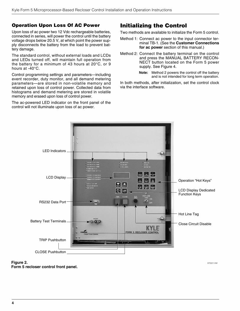
Figure 2. 970021.KM
Form 5 recloser control front panel.
LED Indicators
RS232 Data Port
LCD Display
Battery Test Terminals
Hot Line Tag
Close Circuit Disable
Operation “Hot Keys”
TRIP Pushbutton
CLOSE Pushbutton
LCD Display DedicatedFunction Keys

Current sensing is provided by three current transformerslocated in the recloser housing and interfaced to the Form 5control via the control cable. This cable also supplies Trip,Close, and Recloser status and connects to the RIF moduleto provide isolation for reliable operation. Voltages for meter-ing and control power are also connected to the RIF modulevia the connector terminal block, TB-1 (Figure 3).
A functional block diagram of the Form 5 control is shown inFigure 3. Line current flowing through the recloser is con-verted by the CPU module to a digital signal suitable formetering and fault current calculations. Data samplingoccurs at a rate 32 times per cycle. The CPU contains adata acquisition section that uses the acquired samples tocompute the fundamental currents and voltage for use inovercurrent, under/over voltage, and under/over frequencyprotection, as well as currents and voltages for metering func-tions. The current for overcurrent protection is calculated on asub-cycle basis; it includes only the fundamental and dc com-ponent. For metering, the fundamental and harmonic currentand voltages are determined.
When the phase or ground current exceeds its programmedminimum-trip value and associated time–current curve(TCC) timing, the control initiates the programmed sequenceof recloser tripping and reclosing operations via the CPU andRIF modules. If the fault is temporary, the control ceases tocommand recloser operations after a successful reclosure,and the control resets to the start of its operating sequenceafter a preset time delay. If the fault is permanent, the controlperforms its complete programmed sequence of reclosercommands and locks out with the recloser open. Once
locked out, the control must be closed via the front panel orSCADA communications. This resets the control to the startof the operating sequence.
The following chain of events occurs for an operatingsequence of two trips to lockout:
1. The overcurrent signal is integrated with time on theselected curve for the first trip operation (TCC1) to pro-duce the signal which energizes the trip circuit.
2. Energizing the trip circuit connects the battery and capac-itor to the trip solenoid to open the recloser.
3. Upon opening, the control starts timing on the firstreclosing interval-delay time.
4. Upon expiration of this reclosing interval-delay, a closingsignal is issued from the control, closing the recloser andselecting the time–current characteristics for the secondtrip operation (TCC2).
5. If current remains above the minimum-trip level, the trip-ping and reclosing sequence is repeated.
6. The control begins the reset-delay timer if the overcur-rent is cleared before the operating sequence reacheslockout indicated by a closed recloser and currentbelow minimum trip.
7. When the reset-delay times out, the control is reset tothe home state and is ready for another programmedoperating sequence. If current rises above minimum tripprior to the reset-delay timing out, the timer is haltedand the control resumes the operating sequence whilethe accumulated reset-delay timing is reset.
S280-79-1
5
!SAFETYFOR LIFE
Figure 3.Form 5 control operational flow diagram.
FORM 5 CONTROL DESCRIPTION
BATTERY
TRIP SOLENOID
CLOSE SOLENOID
A Ø CT
B Ø CT
C Ø CT
OPEN / CLOSESWITCHES
CT COMMON
RECLOSER RIF
OPTICALISOLATION
OPTICALISOLATIONOPTICAL
ISOLATION
OPTICALISOLATION
MATCHINGTRANSFORMERS
AND SIGNALCONDITIONING
TB1 TERMINAL BLOCK
CUSTOMER P.T. INPUTS
POWER SUPPLY
CPU CIF
RS232ORF.O.
PORT
RS232ORF.O.
PORT
OPTIONS
OPERATOR'SPANEL
KEYBOARDLED'sLCD
RS232 PORT
DIF#1(OPTIONAL)
DIF#2(OPTIONAL)
USER CONNECTIONS
1212
USER CONNECTIONS

The Form 5 control is constructed in a modular fashion tosimplify servicing and to allow adding accessories with rela-tive ease (see Figure 4). The standard configuration incorpo-rates a Computer Processing Unit (CPU) module, powersupply module, Recloser Interface (RIF) module, Communi-cation Interface module (CIF), and an operator’s panel.
Discrete Interface (DIF) module(s) and fiber-optic/RS232communication interface cards may be ordered as acces-sories. Mounting provisions can be provided to add cus-tomer-supplied radio and modem modules.
Recloser Interface (RIF) ModuleThe Recloser Interface (RIF) Module provides the interfacebetween the recloser and the CPU module, as well as theinterface between the voltage sensors and the CPU module.The RIF is designed to interface with the following reclosers:WE/WVE group, VSA/VSO group, KFME/KFVME (50 Hz)group and NOVA.
The recloser connector includes three current-transformerinputs, Open and Closed status sensing, and Trip and Closecontrols. The voltage sensor connector accepts six voltageinputs; three for source-side, and three for load-side voltage.Six slide-type switches (one for each phase) are mounted onthe module to facilitate loss of voltage testing.
The RIF board accepts either 12, 120, or 240 Vac voltageinputs for metering. The factory configuration is outlined on thefront panel matrix and can be customized to user specification.See RECLOSER INTERFACE (RIF) MODULE CONFIGU-RATION section of this manual.
Computer Processing Unit (CPU)ModuleThe CPU module is the center of the Form 5 control. TheCPU contains a 32-bit micro-controller, a Digital Signal Pro-cessor, RAM and EEPROM memory, and a 16-bit analog-to-digital converter. The CPU module accepts 16 analoginputs which it routes through the digital signal processor,which samples 32 times per cycle, to compute harmonicanalysis to the 15th harmonic.
Communication Interface (CIF)ModuleThe Communications Interface (CIF) module provides thelink between the CPU module and the front operator’s panel.The standard CIF module can also provide the link betweenthe CPU module and all external communications such aspersonal computers, modems, and radios. The CIF canhouse up to two communication interface cards (optional), inaddition to the required Local User Interface (LUIF), plus pro-vide communication to the front operating panel. Direct serialcommunication is achieved via fiber optic or RS232.
Discrete Interface (DIF) ModuleThe Discrete Interface (DIF) module allows users withexisting RTUs the ability to interface with the Form 5 con-trol. The DIF module contains 12 inputs and 12 outputs thatare customized for a remote or supervisory function. EachForm 5 control can accommodate two DIF modules. SeeDISCRETE INTERFACE (DIF) ACCESSORY section ofthis manual.
Kyle Form 5 Microprocessor-Based Recloser Control Installation and Operation Instructions
6
Figure 4.Form 5 control back panel.
98048KM
Control Cable Receptacleand Control Grounding Lug
(located beneath cabinet) Control Batteries
Computer ProcessorModule
Recloser Interface(RIF) Module
TB1 ConnectorBlock
PowerSupplyModule
CommunicationsInterface Module
Discrete Interface ModuleAccessory
Customer-specifiedRadio/Modem AccessoryMounting Provisions
Power Capacitor
Convenience OutletAccessory
RIF Module GroundingStrap
Manual BatteryReconnect Button
Control FeaturesThe Form 5 recloser control offers numerous standardfeatures and accessories that allow the user the utmostflexibility in designing a control suitable for their applica-tion requirements.
Under/Over Frequency LoadsheddingThe Form 5 control includes provisions for frequencyloadshedding that trips the recloser for conditions of underor over system frequency. Access to this feature isthrough frequency threshold, trip time, and allowable volt-age threshold.
With the auto-restoration feature, the Form 5 can be set toclose the recloser after the system frequency and voltagehave recovered. Parameters available for setting includefrequency and voltage thresholds and time delay.
A frequency alarm is available and can be configured fornotification.
Voltage Protection (120 Vac-based)Voltage protection functionality is included as standard onall Form 5 controls. A recloser trip will be issued for underand /over voltage conditions when the monitored voltagefalls outside user specified limits for a selectable time.Response mode include any single phase, all threephases and also single phase with three-phase inhibit.This mode facilitates protecting against a single phasecondition common when a high side fuse operates on adistribution transformer. Parameters are also available toprovide auto restoration after a trip. A voltage alarm isavailable and can be configured for notification.
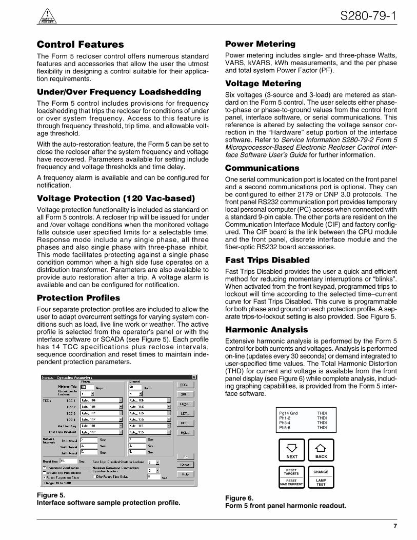
Protection ProfilesFour separate protection profiles are included to allow theuser to adapt overcurrent settings for varying system con-ditions such as load, live line work or weather. The activeprofile is selected from the operator’s panel or with theinterface software or SCADA (see Figure 5). Each profilehas 14 TCC specifications plus reclose intervals,sequence coordination and reset times to maintain inde-pendent protection parameters.
Power MeteringPower metering includes single- and three-phase Watts,VARS, kVARS, kWh measurements, and the per phaseand total system Power Factor (PF).
Voltage MeteringSix voltages (3-source and 3-load) are metered as stan-dard on the Form 5 control. The user selects either phase-to-phase or phase-to-ground values from the control frontpanel, interface software, or serial communications. Thisreference is altered by selecting the voltage sensor cor-rection in the “Hardware” setup portion of the interfacesoftware. Refer to Service Information S280-79-2 Form 5Microprocessor-Based Electronic Recloser Control Inter-face Software User’s Guide for further information.
CommunicationsOne serial communication port is located on the front paneland a second communications port is optional. They canbe configured to either 2179 or DNP 3.0 protocols. Thefront panel RS232 communication port provides temporarylocal personal computer (PC) access when connected witha standard 9-pin cable. The other ports are resident on theCommunication Interface Module (CIF) and factory config-ured. The CIF board is the link between the CPU moduleand the front panel, discrete interface module and thefiber-optic RS232 board accessories.
Fast Trips DisabledFast Trips Disabled provides the user a quick and efficientmethod for reducing momentary interruptions or “blinks”.When activated from the front keypad, programmed trips tolockout will time according to the selected time–currentcurve for Fast Trips Disabled. This curve is programmablefor both phase and ground on each protection profile. A sep-arate trips-to-lockout setting is also provided. See Figure 5.
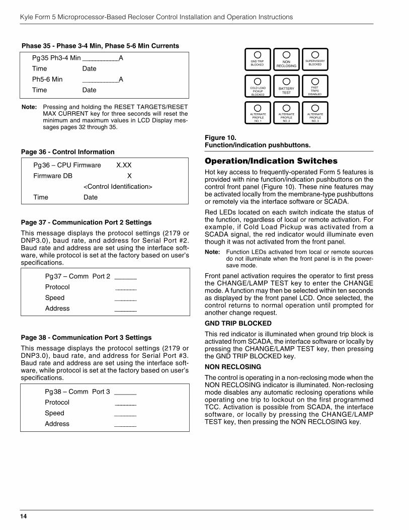
Harmonic AnalysisExtensive harmonic analysis is performed by the Form 5control for both currents and voltages. Analysis is performedon-line (updates every 30 seconds) or demand integrated touser-specified time values. The Total Harmonic Distortion(THD) for current and voltage is available from the frontpanel display (see Figure 6) while complete analysis, includ-ing graphing capabilities, is provided from the Form 5 inter-face software.
S280-79-1
7
!SAFETYFOR LIFE
Figure 5.Interface software sample protection profile.
Figure 6.Form 5 front panel harmonic readout.
NEXT BACK
RESETTARGETS CHANGE
Pg14 Gnd THDIPh1-2 THDIPh3-4 THDIPh5-6 THDI
RESETMAX CURRENT
LAMPTEST

Reverse Power FlowFeeder load monitoring is enhanced with the inclusion of thepower flow monitoring feature. When power flow from theload to the source side of the recloser is detected, the con-trol issues an alarm and illuminates a front-panel indicator.Response time to a reverse power condition is one second.An alarm is also available for remote interrogation.
Hot Line Tag
The Hot Line Tag feature is provided for live-line work application.
Note: All closing operations are disabled when the Hot LineTag feature is activated.
While active, the control utilizes an independent, user-selectable time-current curve for trip operations. Activa-tion is indicated by a three-segment LED located on thefront panel. Also, a close circuit disconnect is included asa removable link in the closing circuit.
Event RecorderThe Event Recorder maintains a rotating log of operatingevents for later readout and analysis by the user. Approx-imately 500 events can be stored in non-volatile memory.For each event type, time of occurrence and other rele-vant information is stored.
HistogramsHistograms in the form 5 are bar graph representations ofthe Form 5’s demand metering. A histogram is availablefor each of the demand metering parameters. The bargraphs display the percentage of time since the last resetthat the metered demand values have been within therange of a bin.
Data ProfilerA fully-configurable data profiler is available which allowsthe user to collect valuable information by sampling dataat selectable intervals. These time-stamped values canthen be plotted to determine weekly load profiles, dailyharmonic disturbances, or hourly voltage fluctuations. Thedata profiler can provide more than 200 days of informa-tion, depending upon configuration parameters.
Cold Load PickupCold Load Pickup (CLPU) is activated from both the oper-ator’s panel and remotely to provide the user with the abil-ity to alter protection for abnormal system conditions. It isactive for a programmable time interval which begins witheach close signal or an automatic reclose signal after aCold Load Pickup trip. Once this time elapses, protectionreverts back to the programmed sequence. The setting’sparameters are made through the Form 5 interface soft-ware (see Figure 7).
Note: When CLPU is active, the control utilizes the Cold LoadPickup TCC, reclose interval, operations to lockout andminimum trip settings in lieu of the normal first operationprotection settings.
AlarmsAlarms are fully programmable to provide the user thecapability to customize the parameters for individualinstallations. The alarms can also be configured to triggera data profile and event record upon initiation. Alarms donot affect the operation of the control.
Form 5 Control Front PanelThe Form 5 control front panel (Figure 8) allows localoperation and status interrogation through built-in opera-tor controls and status displays. The swing-out panel con-tains LED indicators, operational pushbuttons,membrane-type functional/indication switches, backlitLCD display, Hot Line Tag switch with indication, CloseCircuit Disable and battery test terminals. An RS232 portis also provided to permit the temporary connection of aPC for programming the parameters in the control.
All indicators with the exception of Hot Line Tag andrecloser status are automatically turned off after 10 min-utes of front panel inactivity.
Reactivating is accomplished by pressing any operationswitch. The LCD messages will remain while in thispower-saving mode, although the illuminating backlightwill shut off.
Note: The control will not enter into this power-saving modewhen Hot Line Tag is active.
Kyle Form 5 Microprocessor-Based Recloser Control Installation and Operation Instructions
8
Figure 7.Interface software Cold Load Pickup settings.
WARNING: Hazardous voltage. Do not use HotLine Tag as a substitute for a visible disconnect.
Always establish a visible disconnect prior to performingany work requiring a de-energized line. Failure to complymay cause death, severe personal injury, or equipmentdamage. T276.0
!
IMPORTANT: Hot Line Tag activation does not causethe recloser to trip open. It only prevents the recloserfrom reclosing.
IMPORTANT: Hot Line Tag is intended solely for liveline work applications, such as maintenance, repairs, orimprovements to a distribution system that occur whilethe line remains energized.

LED IndicatorsThe front panel LED indicators (Figure 8) give instantinformation on the control and recloser status. They arearranged across the front and down the left side of thefront panel.
LED indicators include:
BUSHINGS 1-2 FAULT TARGET
BUSHINGS 3-4 FAULT TARGET
BUSHINGS 5-6 FAULT TARGET
GROUND FAULT TARGET
SENSITIVE GROUND FAULT TARGET
These red LED indicators illuminate when the controlissues an overcurrent trip signal while the respectivephase current or ground current exceeds the minimumpickup value. Reset is accomplished automatically whenAuto Reset is activated and a successful close operationis performed; manual reset is accomplished by pressingthe RESET TARGETS button on the control front panel.
BUSHINGS 1-2 VOLTAGE
BUSHINGS 3-4 VOLTAGE
BUSHINGS 5-6 VOLTAGE
These red LED indicators illuminate when the control detectsthe presence of voltage on the respective bushings as con-nected to TB1. Refer to the Customer Connections for ACPower section in these instructions to determine the appro-priate power connections.
REVERSE POWER FLOW
This red indicator illuminates when the control detects powerflow from the load side to the source side of the recloser.
RECLOSER MALFUNCTION
This red indicator is illuminated when the control detects afailure in a trip or close operation. It turns off automatically ifthe recloser returns to the proper state.
CHECK BATTERY
This red indicator illuminates for two conditions:
1. When the battery charging or discharging current dropsbelow 10 mA. The LED will automatically shut off whencurrent returns above the threshold.
2. When the control fails a manual battery test, the LED willremain on until a successful battery test is completed.
Refer to the Battery Test Procedure in this manual for moreinformation.
RECLOSER CLOSED
This red indicator is illuminated when the control senses thatthe recloser mechanism is in the closed position.
RECLOSER OPEN
This green indicator is illuminated when the control sensesthat the recloser mechanism is in the open position.
CONTROL LOCKOUT
This green indicator is illuminated when the recloser is openand a reclosing sequence is not in progress or when the lock-out handle on the recloser mechanism is in the down posi-tion; i.e., trip and close circuits are open.
CONTROL OK
This green indicator is illuminated when the continuous self-diagnostics of the control have detected no CPU or memorymalfunctions and indicate that the control is capable of nor-mal operation.
AC POWER
This green indicator is illuminated when the presence of acinput power to the control is sensed.
ABOVE MIN TRIP
This red indicator is illuminated when the control detects thatcurrent is above the programmed minimum trip value forBushings 1-2, Bushings 3-4, Bushings 5-6, Ground, or Sen-sitive Ground.
S280-79-1
9
!SAFETYFOR LIFE
Figure 8.Form 5 control front panel.
BUSHING 1-2 FAULT TARGET
BUSHING 3-4 FAULT TARGET
BUSHING 5-6 FAULT TARGET
GROUND FAULT TARGET
SENSITIVE GROUND FAULT TARGET
BUSHING 1-2 VOLTAGE
BUSHING 3-4 VOLTAGE
BUSHING 5-6 VOLTAGE
REVERSE POWER FLOW
RECLOSER MALFUNCTION
CHECK BATTERY
RECLOSER CLOSED
RECLOSER OPEN
CONTROL LOCKOUT
CONTROL OK
AC POWER
ABOVE MIN TRIP
GND TRIPBLOCKED
NONRECLOSING
SUPERVISORYBLOCKED
COLD LOADPICKUP
BLOCKED
BATTERYTEST
FASTTRIPS
DISABLED
ALTERNATEPROFILE
NO. 1
ALTERNATEPROFILE
NO. 2
ALTERNATEPROFILE
NO. 3NEXT BACK
RESETTARGETS
CHANGE
LAMPTEST
TRIP(LOCKOUT) CLOSE
HOT LINETAG
ON
OFF
CLOSECIRCUITDISABLE
RS232PORT
LED Indicators
LCD Display
TRIP (LOCKOUT)Pushbutton
CLOSEPushbutton
RESETMAX CURRENT

Kyle Form 5 Microprocessor-Based Recloser Control Installation and Operation Instructions
10
TRIP (Lockout) PushbuttonThe TRIP pushbutton (Figure 8) provides front-panelaccess to trip (lockout) the recloser. When pressed, theTRIP push-button opens the recloser and locks out thecontrol. This operation supersedes commands made in theSupervisory function; i.e., the TRIP (LOCKOUT) pushbut-ton will override SUPERVISORY commands in all cases.
CLOSE PushbuttonWhen pressed, the CLOSE pushbutton (Figure 8) returnsthe control to the initial or home position and closes therecloser.
Note: Cold-Load Pickup is programmed using the interfacesoftware and activated through front panel hot keys.Pressing the CLOSE pushbutton will initiate Cold-LoadPickup protection if the feature is active as indicated bythe front-panel LED. Holding the CLOSE pushbutton indoes not activate and has no effect on the feature. Referto the interface software program to determine the acti-vation time and time–current characteristic applicablefor Cold-Load Pickup.
LCD DisplayThe control front panel has a large, backlit LCD display(Figure 9) used for viewing control parameters and moni-toring system conditions. Data is organized onto 38 mes-sages or “pages” of information, with each pagecontaining four lines of information, with up to 20 charac-ters per line. Access to the messages is obtained throughnavigational keys which permit the user to scroll throughthe menu in a timely and efficient manner.
When an overcurrent trip occurs, the control automaticallydisplays the fault current values as shown on the LCD dis-play as Page 1 (see LCD Display Messages section ofthis manual).
NEXT KeyPressing the NEXT key causes the LCD display to scrollto the next message or “page” of available information onthe 4-line by 20-characters per page LCD display. Press-ing and holding the NEXT key causes the control to scrollto subsequent pages at the rate of about two pages persecond.
BACK KeyPressing the BACK key causes the LCD display to scroll tothe previous message or “page” of available information onthe 4-line by 20-characters per page LCD display. Press-ing and holding the BACK key causes the control to scrollto previous pages at the rate of two pages per second.
RESET TARGETS/RESET MAXCURRENT KeyPressing the RESET TARGETS/RESET MAX CURRENTkey will reset the fault target indicators on the control frontpanel. The fault current values shown on Page 1 of theLCD display will reset to values of zero.
Pressing and holding the RESET TARGETS/RESETMAX CURRENT key for three seconds will reset the min-imum and maximum values in LCD Display messages(pages 32 through 35).
CHANGE/LAMP TEST KeyPressing this key for less than three seconds places thecontrol into a CHANGE mode for 10 seconds as indicatedby the LCD display. CHANGE mode permits the user tochange the state of the nine function/indicator switches onthe front panel. Security is ensured by permitting a singleselection for each CHANGE mode period.
Pressing and holding the CHANGE/LAMP TEST key forthree seconds will cause the control to perform a front-panel lamp test. In the Lamp Test Mode, the status indi-cators flash three times (one second on, one second off).All status indicators then return to their previous on/offstate. While in the Lamp Test Mode, the controlresponses to front panel keys are disabled, except forresponses to the TRIP (LOCKOUT), CLOSE, and HOTLINE TAG switches.
Figure 9.LCD display and dedicated function keys.
NEXT BACK
RESETTARGETS
CHANGE
LAMPTEST
TRIP(LOCKOUT) CLOSE
RESETMAX CURRENT

LCD Display MessagesEvery message or “page” contains a parameter name,parameter value, and parameter units. If the controldetects that a parameter value is invalid, the LCD displayshows five dash characters (- - - - -) in the value field of themessage. Demand metered values are indicated by (D)and instantaneous values by (I).
S280-79-1
11
!SAFETYFOR LIFE
1 Gnd ____________ A
Ph1-2 ____________ A
Ph3-4 ____________ A
Ph5-6 ____________ A
Pg 2 Gnd Fault A
Ph1-2 Fault ____________ A
Ph3-4 Fault ____________ A
Ph5-6 Fault ____________ A
Pg3 Freq Trip____________ Hz
Time Date
Present Freq ____________ Hz
Pg4 Ph1-2 Trip ____________ V
Ph3-4 Trip ____________ V
Ph5-6 Trip ____________ V
Time Date
Pg5 Tot ____________ kWh
Ph1-2 ____________ kWh
Ph3-4 ____________ kWh
Ph5-6 ____________ kWh
Pg6 S1 Ph-N Instant
Ph1-N ____________ V
Ph3-N ____________ V
Ph5-N ____________ V
Pg7 S1 Ph-Ph Instant
Ph1-3 ____________ V
Ph3-5 ____________ V
Ph5-1 ____________ V
Pg8 S2 Ph-N Instant
Ph2-N ____________ V
Ph4-N ____________ V
Ph6-N ____________ V
Pg9 S2 Ph-Ph Instant
Ph2-4 ____________ V
Ph4-6 ____________ V
Ph6-2 ____________ V
Pg10 Tot ____________ kW
Ph1-2 ____________ kW
Ph3-4 ____________ kW
Ph5-6 ____________ kW
Pg11 Tot ____________ kVA
Ph1-2 ____________ kVA
Ph3-4 ____________ kVA
Ph5-6 ____________ kVA
Page 1 - Instantaneous Current
Page 1 displays line current values present for the lastovercurrent trip operation. Values are reset to zero whenthe fault targets are reset.
Page 2 - Fault Targets
Page 3 - Frequency Trip
Page 4 - Voltage Trip
Page 5 - Power kWh
Page 6 - S1 Phase-to-Neutral, Instantaneous Voltage
Page 7 - S1 Phase-to-Phase, Instantaneous Voltage
Page 8 - S2 Phase-to-Neutral, Instantaneous Voltage
Page 9 - S2 Phase-to-Phase, Instantaneous Voltage
Page 10 - Real Power
Page 11 - Instantaneous kVA

Kyle Form 5 Microprocessor-Based Recloser Control Installation and Operation Instructions
12
Pg17 S1 Ph-Ph Demand
Ph1-3 (d) ____________ V
Ph3-5(d) ____________ V
Ph5-1(d) ____________ V
Pg18 S2 Ph-N Demand
Ph2-N(d) ____________ V
Ph4-N(d) ____________ V
Ph6-N(d) ____________ V
Pg12 Tot ____________ kVAR
Ph1-2 ____________ kVAR
Ph3-4 ____________ kVAR
Ph5-6 ____________ kVAR
Pg13 Tot ____________ PF
Ph1-2 ____________ PF
Ph3-4 ____________ PF
Ph5-6 ____________ PF
Pg14 Gnd ____________ %THDI
Ph1-2 ____________ %THDI
Ph3-4 ____________ %THDI
Ph5-6 ____________ %THDI
Pg15 Gnd ____________ %THDV
Ph1-2 ____________ %THDV
Ph3-4 ____________ %THDV
Ph5-6 ____________ %THDV
Pg16 S1 PH-N Instant
Ph1-N(d) ____________ V
Ph3-N(d) ____________ V
Ph5-N(d) ____________ V
P19 S2 Ph-Ph Demand
Ph2-4(d) ____________ V
Ph4-6(d) ____________ V
Ph6-2(d) ____________ V
P20 Gnd(d) ____________ A
Ph1-2(d) ____________ A
Ph3-4(d) ____________ A
Ph5-6(d) ____________ A
P21 Tot(d) ____________ kW
Ph1-2(d) ____________ kW
Ph3-4(d) ____________ kW
Ph5-6(d) ____________ kW
P22 Tot(d) ____________ kVA
Ph1-2(d) ____________ kVA
Ph3-4(d) ____________ kVA
Ph5-6(d) ____________ kVA
P23 Tot(d) ____________ kVAR
Ph1-2(d) ____________ kVAR
Ph3-4(d) ____________ kVAR
Ph5-6(d) ____________ kVAR
Page 12 - Instantaneous kVAR
Page 17 - S1 Ph-Ph Demand Voltage
Page 16 - S1 Ph-N Demand Voltage
Page 15 - Instantaneous THD Voltage
Page 14 - Instantaneous THD Current
Page 13 - Instantaneous Power Factor
Page 18 - S2 Ph-N Demand Voltage
Page 23 - Demand kVAR
Page 22 - Demand kVA
Page 21 - Demand kW
Page 20 - Demand Current
Page 19 - S2 Ph-Ph Demand Voltage

S280-79-1
13
!SAFETYFOR LIFE
Pg28 SGF trips ______
Operations ______
Pg29 Battery Monitor
Normal Volts _______ V
Normal Current _____ mA
Test Volts _______ V
Pg30 – Phase MT ______ A
ALT1 MT ______ A
ALT2 MT ______ A
ALT3 MT ______ A
Pg31 – Gnd MT ______ A
ALT1 MT _______ A
ALT2 MT ______ A
ALT3 MT _______ A
Pg24 Tot(d) ____________ PF
Ph1-2(d) ____________ PF
Ph3-4(d) ____________ PF
Ph5-6(d) ____________ PF
Pg25 Gnd(d)____________ %THDI
Ph1-2(d) ____________ %THDI
Ph3-4(d) ____________ %THDI
Ph5-6(d) ____________ %THDI
Pg26 Gnd (d) ____________ %THDV
Ph1-N(d) ____________ %THDV
Ph3-N(d) ____________ %THDV
Ph5-N(d) ____________ %THDV
Pg27 Gnd Trips
Ph1-2 Trips ____________
Ph1-3 Trips ____________
Ph5-6 Trips ____________
Pg32 Gnd Max ____________A
Time Date
Ph1-2 Max ____________A
Time Date
Pg33 Ph 3-4 Max ____________A
Time Date
Ph5-6 Max ____________A
Time Date
Pg34 Gnd Min ____________A
Time Date
Ph1-2 Min ____________A
Time Date
Page 24 - Demand Power Factor
Page 25 - Demand THD Current
Page 26 - Demand THD Voltage
Page 27 - Number of Trips for Ground and Phase
Page 28 - SGF Target and Operations Counter, Timeand Date
Page 29 - Battery Monitor
The Battery Monitor displays the battery voltage, current,and voltage during a battery test. The Battery Monitor isused with the Battery Test pushbutton. Refer to the Bat-tery Test Procedure section of these instructions for moreinformation.
Page 30 - Phase Minimum Trip Settings
Phase minimum trip settings are listed for the four pro-tection profiles. Line 1 is the normal setting, ALT1 is pro-file No. 1, ALT2 is profile No. 2, and ALT3 is profile No. 3.Phase Minimum Trip Settings allow verification of trip set-tings before selection of an alternate profile.
Page 31 - Ground Minimum Trip Settings
Ground minimum trip settings are listed for the four pro-tection profiles. Line 1 is the normal setting, ALT1 is pro-file No. 1, ALT2 is profile No. 2, and ALT3 is profile No. 3.Ground Minimum Trip Settings allow verification of tripsettings before selection of an alternate profile.
Page 32 - Ground Max, Phase 1-2 Max Currents
Page 33 - Phase 3-4 Max, Phase 5-6 Max Currents
Page 34 - Ground Min, Phase 1-2 Min Currents
Operation/Indication SwitchesHot key access to frequently-operated Form 5 features isprovided with nine function/indication pushbuttons on thecontrol front panel (Figure 10). These nine features maybe activated locally from the membrane-type pushbuttonsor remotely via the interface software or SCADA.
Red LEDs located on each switch indicate the status ofthe function, regardless of local or remote activation. Forexample, if Cold Load Pickup was activated from aSCADA signal, the red indicator would illuminate eventhough it was not activated from the front panel.
Note: Function LEDs activated from local or remote sourcesdo not illuminate when the front panel is in the power-save mode.
Front panel activation requires the operator to first pressthe CHANGE/LAMP TEST key to enter the CHANGEmode. A function may then be selected within ten secondsas displayed by the front panel LCD. Once selected, thecontrol returns to normal operation until prompted foranother change request.
GND TRIP BLOCKED
This red indicator is illuminated when ground trip block isactivated from SCADA, the interface software or locally bypressing the CHANGE/LAMP TEST key, then pressingthe GND TRIP BLOCKED key.
NON RECLOSING
The control is operating in a non-reclosing mode when theNON RECLOSING indicator is illuminated. Non-reclosingmode disables any automatic reclosing operations whileoperating one trip to lockout on the first programmedTCC. Activation is possible from SCADA, the interfacesoftware, or locally by pressing the CHANGE/LAMPTEST key, then pressing the NON RECLOSING key.
Kyle Form 5 Microprocessor-Based Recloser Control Installation and Operation Instructions
14
GND TRIPBLOCKED
NONRECLOSING
SUPERVISORYBLOCKED
COLD LOADPICKUP
BLOCKED
BATTERYTEST
FASTTRIPS
DISABLED
ALTERNATEPROFILE
NO. 1
ALTERNATEPROFILE
NO. 2
ALTERNATEPROFILE
NO. 3
Figure 10.Function/indication pushbuttons.
Pg35 Ph3-4 Min ____________A
Time Date
Ph5-6 Min ____________A
Time Date
Pg38 – Comm Port 3 ______
Protocol _______
Speed _______
Address _______
Pg37 – Comm Port 2 ______
Protocol _______
Speed _______
Address _______
Pg36 – CPU Firmware X.XX
Firmware DB X
<Control Identification>
Time Date
Phase 35 - Phase 3-4 Min, Phase 5-6 Min Currents
Page 38 - Communication Port 3 Settings
This message displays the protocol settings (2179 orDNP3.0), baud rate, and address for Serial Port #3.Baud rate and address are set using the interface soft-ware, while protocol is set at the factory based on user’sspecifications.
Page 37 - Communication Port 2 Settings
This message displays the protocol settings (2179 orDNP3.0), baud rate, and address for Serial Port #2.Baud rate and address are set using the interface soft-ware, while protocol is set at the factory based on user’sspecifications.
Page 36 - Control Information
Note: Pressing and holding the RESET TARGETS/RESETMAX CURRENT key for three seconds will reset theminimum and maximum values in LCD Display mes-sages pages 32 through 35.

SUPERVISORY BLOCKED
When the SUPERVISORY BLOCKED indicator is illumi-nated, supervisory SCADA and interface software are dis-abled; remote SCADA remains active. Activation of theswitch is restricted to the front panel and is accomplishedby pressing the CHANGE/LAMP TEST key, then pressingthe SUPERVISORY BLOCKED key. Operational data andmetering information are available while the control is in theSUPERVISORY BLOCKED position. The TRIP andCLOSE pushbuttons are active independently of theSUPERVISORY BLOCKED function.
COLD LOAD PICKUP BLOCKED
The Cold Load Pickup feature is blocked while the COLDLOAD PICKUP BLOCKED indicator is illuminated. WhenCLPU is not blocked, the control utilizes the Cold LoadPickup TCC, reclose interval, operations to lockout andminimum trip settings in lieu of the normal first operationprotection settings. This function may be toggled fromSCADA, the interface software, or locally by pressing theCHANGE/LAMP TEST key, then pressing the COLDLOAD PICKUP BLOCKED key.
BATTERY TEST
The BATTERY TEST indicator illuminates when the con-trol is performing a battery test. It turns off automaticallywhen the control has finished performing the test. Testingis initiated remotely via SCADA or from the interface soft-ware, or locally by pressing the CHANGE/LAMP TESTkey, then pressing the BATTERY TEST key. Refer to theBattery Test section of these instructions for furtherdetails on testing the control battery.
FAST TRIPS DISABLED
Fast Trips Disabled commands the control to use the pro-grammed Fast Trips Disabled time–current curve for alltripping operations. When in the Fast Trips Disabledmode, the indicator will be illuminated. The function isactivated from SCADA, the interface software, or locallyby pressing the CHANGE/LAMP TEST key, then pressingthe FAST TRIPS DISABLED key.
ALTERNATE PROFILE Indicator/Key
The control has four separate protection profiles; a normalprofile, and Alternate Profiles 1, 2, and 3. Each profilechanges all protection parameters for the control. Exceptfor the normal profile, each has an indication and selec-tion key. When the front panel display lights are active andnone of the three indicators are on, the normal profile isactive. To select an alternate profi le, press theCHANGE/LAMP TEST key, then press the desired alter-nate profile. To return to the normal profile, simply turn offthe active alternate profile. These functions can also beoperated remotely via available communications inter-faces.
Note: The minimum trip values for each protection profile areshown on Pages 30 and 31 of the LCD display. Checkthese minimum trip values prior to changing an alternateprofile to avoid misoperation of the control under loadconditions.
HOT LINE TAG Switch
Hot Line Tag is provided for live-line work applications.All closing operations are disabled when the Hot LineTag feature is activated. While active, the control utilizesan independent, user-selectable, time current curve fortrip operations.
The Hot Line Tag feature (Figure 11) consists of a tog-gle switch and a three-segment LED indicator which illu-minates when the function is active. When active, HotLine Tag prevents all closing attempts and shifts protec-tion to one trip to lockout on the programmed time-cur-rent curve. The Hot Line Tag function takes precedenceover Cold Load Pickup, Non Reclosing and Fast TripsDisabled. Activation is accomplished by placing the frontpanel toggle switch to the “up” position, or via SCADAcommand. The Hot Line Tag feature may only be resetby the source that initiates the function. For example, ifHot Line Tag is activated at the front panel, the resetfunction is only possible at the front panel, and not viaSCADA command.
Hot Line Tag includes a CLOSE CIRCUIT DISABLE fea-ture that provides visible disconnect in the close circuit.The CLOSE CIRCUIT DISABLE feature (Figure 11) con-sists of a removable, solid-bus cartridge connected inseries with the close circuit of the recloser. Removing thecartridge from the control disables all electrical closing ofthe recloser and provides a physical disconnect to therecloser closing circuit.
S280-79-1
15
!SAFETYFOR LIFE
Figure 11.Hot Line Tag and Close Circuit Disable.
970021KM
WARNING: Hazardous voltage. Do not use HotLine Tag as a substitute for a visible disconnect.
Always establish a visible disconnect prior to performingany work requiring a de-energized line. Failure to complymay cause death, severe personal injury, or equipmentdamage. T276.0
!
IMPORTANT: Hot Line Tag activation does not causethe recloser to trip open. It only prevents the recloserfrom reclosing.
IMPORTANT: Hot Line Tag is intended solely for liveline work applications, such as maintenance, repairs, orimprovements to a distribution system that occur whilethe line remains energized.

RS232 Communication PortThe standard Form 5 control is equipped with a front panelRS232 port for interface with a personal computer runningthe Form 5 interface software program. This nine-pin com-munication port permits the uploading of all programminginformation stored in the control, including protection pro-files, event recorder, data profiles, alarms, counters, andmetering information. The communication port also pro-vides a simple means to download operating parametersfrom a personal computer to the control.
Note: The front panel RS232 port is designed only for temporaryconnection of a personal computer. For surge immunityreasons, all permanent serial communications must bemade via the Communications Interface Module (CIF).
Battery Test TerminalsThe control monitors the state of the 24 Vdc battery on acontinual basis as part of the self-check features. Moni-tored values include voltage and load/charging current.In addition to the self-checking features, battery test ter-minals are provided on the front panel for verification ofbattery condition (Figure 12). Voltage test terminals pro-vide battery voltages for both normal and battery-testconditions.
Battery Test ProcedureThe BATTERY TEST hot key on the front panel providesa quick and easy method for testing the condition of thecontrol battery. This key, combined with the LCD readout,eliminates the need for an external current/voltage meterwhen testing the battery.
When a battery test is initiated, the spurious charge is firstdrained to allow the battery voltage to equalize. A 10 Ω,55 W resistor is then placed across the battery terminalsand a voltage drop is calculated. If the drop from theequalized voltage to the test voltage exceeds 2 V, thenthe CHECK BATTERY LED is illuminated.
To perform a battery test:
1. Using the Next and BACK keys, scroll through theLCD display to Page 29, the Battery Monitor page.
2. Record the NORMAL VOLTS and NORMAL CUR-RENT readings from the screen. Voltage should bebetween 31 and 25 V with higher readings at coldertemperatures. Under normal conditions with ac con-nected and the battery trickle charging, the currentshould read between 12 mA and 20 mA. With ac con-nected and in bulk charging mode, current will rangefrom 12 to 600 mA. With ac disconnected and the bat-tery supplying the load, current will read -20 mA to -3A depending on accessories connected. Service thebattery if the readings exceed these limits.
3. Momentarily, press the CHANGE/LAMP TEST key,then BATTERY TEST key.
Note: AC power can be either connected or disconnectedfor Step 3.
4. Record the TEST VOLTS reading from the LCD andthe status of the CHECK BATTERY LED. Service thebattery if the CHECK BATTERY LED is illuminated.
Battery Replacemnet andDisposalThe control batteries have a life expectancy of three tofive years. It is recommended that the batteries bereplaces after four years.
Dispose of expired batteries in an environmentallyresponsible manner. Consult local regulations for properbattery disposal.
Check BatteryThe red indicator illuminates when the control fails a bat-tery test. A failed test can indicate any of these conditions.
• The measured battery voltage is less than 22 V.
• The battery voltage drops more than 2 V during thebattery test.
• A battery is not in the unit or the battery is open.
The other LED will remain on until a new battery isinstalled or other corrective action occurs and a success-ful battery test is completed. Refer to Battery Testingand Charging Procedures in the Testing section of thismanual for more information.
Kyle Form 5 Microprocessor-Based Recloser Control Installation and Operation Instructions
16
VOM
Figure 12.Form 5 control battery test terminals.

RECLOSER INTERFACE (RIF)MODULE CONFIGURATION
The Recloser Interface (RIF) Module is factory-configuredat 120 Vac. For operating voltages other than 120 Vac,the RIF module must be removed from the control cabinetfor configuration.
The Form 5 control must be completely de-energized priorto removing and configuring the RIF board. To remove theRIF board:
1. Remove the control battery located under the RIFmodule.
2. Release the clips securing the three wiring harnessconnectors.
3. Remove the nut and disconnect the RIF modulegrounding strap to the front panel. See Figure 4.
4. Disconnect the three wiring harnesses from the frontof the RIF panel.
5. Disconnect the P8 Voltage Sensor connector.
6. Remove the four 11 mm (.437 in.) screws securing theboard to the mounting bracket.
7. Pull the module out of the cabinet.
The DIP switches are located on the side of the module.
8. Configure the RIF board as shown in Figure 13.
9. After configuration, place the module back into posi-tion in the control cabinet and secure to the mountingbracket with screws previously removed.
10. Replace nut securing the RIF module grounding strap.
S280-79-1
17
!SAFETYFOR LIFE
CAUTION: Equipment damage. Always wear a ground-ing wrist strap to control static electricity before handlingcircuit boards. Failure to use this strap may result in cir-cuit board damage. T253.1
INPUT VOLTAGESELECTION
INPUT VOLTAGESELECTION
POLE 2POLE 1POLE 2
POLE 1
S7
S8
POLE 1
POLE 2
POLE 2POLE 1POLE 2
POLE 1
POLE 1
POLE 2
S7
BUSHING 2 (XØ)
BUSHING 4 (YØ)
BUSHING 6 (ZØ)
BUSHING 1 (AØ)
BUSHING 3 (BØ)
BUSHING 5 (CØ)
OFF ON
OFF ON
SENSOR VOLTAGE POLE1 POLE2
12 Vac OFF OFF 120 Vac* OFF ON 240 Vac ON ON
Example shown for 120 Vac operation:
*120Vac is factory-set configuration
Figure 13.Recloser Interface (RIF) Module configuration.

The UDP function allows the Form 5 control to become aswitch control to provide indication of overcurrent trip con-ditions without issuing an overcurrent trip signal. The con-trol is in the recloser mode when the feature is in the OFFposition, and in the switch mode when the feature isACTIVE. This non-tripping fault indication state is initiatedvia a front panel pushbutton (labeled SWITCH MODE),digital SCADA, or discrete SCADA. The UDP feature haslocal indication at the front panel (LED), digital indication,and remote indication via status contacts on the DiscreteInterface (DIF) module 1. Refer to Figures 14 and 15.
Kyle Form 5 Microprocessor-Based Recloser Control Installation and Operation Instructions
18
Figure 15.Interface software Switch Mode settings
GND TRIPBLOCKED
NONRECLOSING
SUPERVISORYBLOCKED
COLD LOADPICKUP
BLOCKED
BATTERYTEST
FASTTRIPS
DISABLED
ALTERNATEPROFILE
NO. 1
ALTERNATEPROFILE
NO. 2
SWITCHMODE
Figure 14.Function/Indication pushbuttons for the Form 5equipped with the UDP accessory.
FORM 5 UNIVERSAL DEVICE PROTECTION (UDP) CONTROL

The Kyle Form 5 recloser control can be equipped with adc-to-dc converter, interface circuit, and a fully shielded19-pin cable for use with a Type NOVA recloser with adc interface only. See Figure 16.
The dc-to-dc converter board (Figure 23) converts thecontrol’s 24 Vdc battery supply voltage to 53 Vdc to drivethe trip/close capacitors in the NOVA mechanism. Theoutput of the board is separately fused for operator indi-cation. See Figures 17–19.
The dc-to-dc converter houses voltage monitoring andconditioning circuits which protect the battery from failureand provides trip/close operations without ac power. The19-pin control cable interfaces the NOVA dc recloser tothe Form 5 control through the interface circuit. The cablealso provides ac power from the control to the reclosermechanism heater.
S280-79-1
19
!SAFETYFOR LIFE
FORM 5 DC NOVA CONTROL
Figure 17. 98042KM
Dc-to-dc converter located in the bottom of controlcabinet. (Control batteries and battery bracketremoved.)
Figure 19. 98043KM
Dc-to-dc converter board.
Figure 18. 98041KM
Dc interface circuit board.
Form 5Control
PotentialTransformer (120/240Vac)
120Vac/240VacPower Cable
19 Pin Control Cable
OP
EN
NOVA dc
Figure 16.Connections of a Form 5 control with dc NOVAaccessory to a NOVA dc recloser.

DISCRETE INTERFACE (DIF)ACCESSORY
The Discrete Interface (DIF) module accessory (Figure 20)permits connection of contact-type input devices(switches, relays) and discrete indicating devices (relays,LEDs, lamps) to the Form 5 control to affect local discreteinput/output (I/O). The DIF module accessory is used forsupplementing normal local controls and status indicatorsfor discrete SCADA functions. All DIF inputs and outputscan be factory-set to customer specifications.
The DIF module contains 12 inputs and 12 outputs thatare customized for a remote or SCADA function. EachForm 5 control can accommodate two DIF modules.
Whetting voltage for the DIF inputs can be supplied by theDIF module or by the customer as shown in Figure 21.
Note: The DIF module provides 28 Vdc (nominal) via connec-tor P5 for use as whetting voltage for inputs to P4. As analternative, the user can supply whetting voltage froman auxiliary source, such as an RTU.
The input voltage range is 12 to 120 Vac or Vdc. The 12outputs are Form C relay contacts. Six of the module out-puts are latching and the other six are non-latching.
Note: Latching is defined as an output that retains its statuswhen power is removed from that output.
Non-latching is defined as an output that changes itsstatus when power is removed from that output.
Note: A remote function is not controlled by the SUPERVI-SORY BLOCKED switch.
Customer ConnectionInformation
Figure 21 shows the customer-supplied wiring of whettingvoltage for DIF module inputs. Connection is made fromterminal P5 on the DIF module to the respective connec-tions on P4 inputs 1 through 12.
Figure 22 shows customer connections to the DIF outputsat P2 and P3. Connections are customized per customerapplication.
Standard and UDP ControlsStandard and UDP Form 5 control DIF inputs and outputsare described in the following pages.
Kyle Form 5 Microprocessor-Based Recloser Control Installation and Operation Instructions
20
4
3
2
1
4321
8765
1211109
6
5
4
3
2
1
4321
8765
1211109
12
11
10
9
8
7
4321
8765
1211109
INPUT COMMON
28V (-)28V (+)
OUTPUT COMMON
DISCRETE INTERFACEMODULE ACCESSORY
P5WHETTINGVOLTS
P3UNLATCHEDOUTPUTS
P2LATCHEDOUTPUTS
P4INPUTS(12 TO 120VAC OR VDC)WHETTINGVOLTAGE
4321
8765
1211109
Figure 20.Discrete Interface (DIF) Module.
4
3
2
1
INPUT COMMON
28V (-)28V (+)
OUTPUT COMMON
To P4Inputs 1 thru 12
P5
Customer-SuppliedWiring for Whetting Voltage
REMOTECONTACTS
Figure 21.Customer connections for supplying whetting voltageto DIF inputs.
IMPORTANT: The DIF should not be used for over-current protection. The control gives priority to TCC tim-ing and issuing a trip signal rather than changing thestatus of a DIF input.
CAUTION: Equipment damage. Do not drill con-nection holes into the top of the cabinet. Connec-
tion holes in the top of the cabinet will allow moisture toseep into the control and damage the components orcause control misoperation. Failure to comply will voidthe control’s factory warranty. T249.0
!
CAUTION: Equipment damage; misoperation.External leads must be shielded and the shield
must be grounded at both ends. Terminate each leadwith a 320 Vac, 160 Joules metal oxide varistor (MOV),or equivalent, at the remote end. Attach MOV’s betweenthe leads and ground. Failure to properly shield and pro-tect leads can result in equipment damage and/or unin-tentional operation. G117.3
!

S280-79-1
21
!SAFETYFOR LIFE
R
FORM 5 CONTROL
Remote Terminal Unit (RTU)
NORMAL PROFILE
NON-RECLOSING
INPUT CONTROL COMMON
SUPV. CLOSE
SUPV. TRIP & L.O.
Not All RemoteConnections
Shown
67
85
12
43
910
1112
Discrete InterfaceModule (DIF)
REMOTE HOT LINE TAG
SUPERVISORY GROUND TRIP BLOCKED
SUPERVISORY ALTERNATE PROFILE 1
SUPERVISORY ALTERNATE PROFILE 2
SUPERVISORY ALTERNATE PROFILE 3(SWITCH MODE ON FORM 5 UDP)
SUPERVISORY NORMAL PROFILE
SUPERVISORY NON-RECLOSING
SUPERVISORY COLD LOAD PICKUP BLOCKED
REMOTE TRIP AND RECLOSE
REMOTE TRIP AND LOCKOUT
SUPERVISORY BLOCKED
AC POWER
CONTROL OK
RECLOSER OPEN
HOT LINE TAG
GROUND TRIP BLOCKED
ALTERNATE PROFILE 1
ALTERNATE PROFILE 2
ALTERNATE PROFILE 3
P5
P3
P4
P2
28V (-)
28V (+)
OUTPUT STATUS COMMON
67
85
12
43
910
1112
67
85
12
43
910
1112
INPUTVOLTAGE
OUTPUTSTATUSCOMMON
COLD LOAD PICKUP BLOCKED
CONTROLPOINTS
STATUSPOINTS
STATUSPOINTS
28VDC (NOMINAL) SUPPLIED BYDIF MODULE FOR WHETTING
VOLTAGE
Figure 22.Customer connections to DIF module outputs with shielding and surge protection.

Kyle Form 5 Microprocessor-Based Recloser Control Installation and Operation Instructions
22
Maximum Switching Voltage: . . . . . 135 Vac 110 Vdc
Maximum Switching Loading: . . . . . 600 mA
Maximum Pickup-Release Time: . . 3 msec (Does not count control response time.)
Output Protection: . . . . . . . . . . . . . . Shunting type using MOV’s and capacitors
Minimum Detection Level: . . . . . . . . . . . . . . . . . . . . 8 Vac (50 or 60 Hz) 10 Vdc
Maximum Operating Voltage: . . . . . . . . . . . . . . . . . . 135 Vac (50 or 60 Hz) 175 Vdc
Input Impedance: . . . . . . . . . . . . . . . . . . . . . . . . . . . 10 K minimum (Inputs are current limited.)
Maximum Input Loading: . . . . . . . . . . . . . . . . . . . . . 2 mA per input
Maximum Leakage Rejection: . . . . . . . . . . . . . . . . . 1 mA
Maximum Pickup Time: . . . . . . . . . . . . . . . . . . . . . . 10 msec (Does not count control response time.)
Minimum Input Pulse Time . . . . . . . . . . . . . . . . . . . . 100 msec
Minimum Transition Time Between Pulse Inputs . . . 200 msec
Input Protection . . . . . . . . . . . . . . . . . . . . . . . . . . . . Shunting type using MOV’s and capacitors.Opto Isolation from input to system
Voltage Level: . . . . . 28 Vdc (nominal)
Output Current: . . . . 30 mA maximum
TABLE 1DIF Input Ratings
TABLE 2Whetting Voltage of DIF Inputs
TABLE 3DIF Status Output Ratings
IMPORTANT: Each DIF contains a small, isolated cur-rent source for use with external dry contacts. This sup-ply is intended for use with the DIF inputs only and maybe used for powering external circuits. This is consid-ered a dry contact input for customer connection.
S280-79-1
23
!SAFETYFOR LIFE
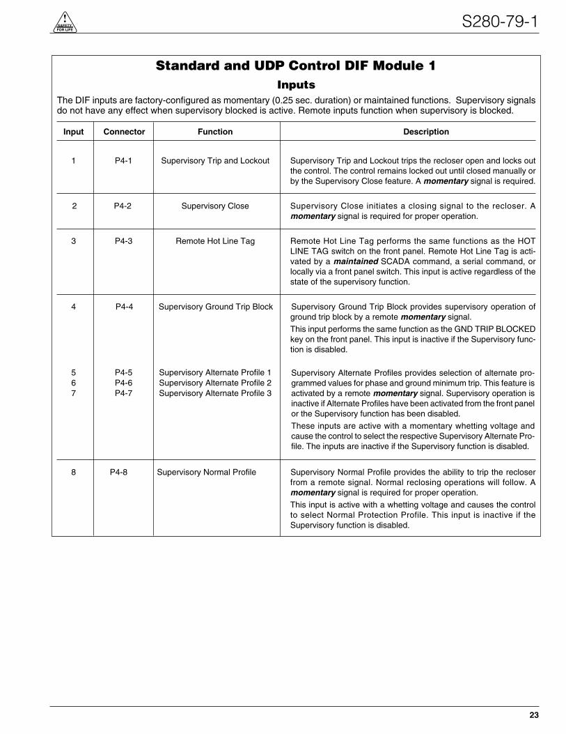
Standard and UDP Control DIF Module 1Inputs
The DIF inputs are factory-configured as momentary (0.25 sec. duration) or maintained functions. Supervisory signalsdo not have any effect when supervisory blocked is active. Remote inputs function when supervisory is blocked.
Input Connector Function Description
1 P4-1 Supervisory Trip and Lockout Supervisory Trip and Lockout trips the recloser open and locks outthe control. The control remains locked out until closed manually orby the Supervisory Close feature. A momentary signal is required.
2 P4-2 Supervisory Close Supervisory Close initiates a closing signal to the recloser. Amomentary signal is required for proper operation.
3 P4-3 Remote Hot Line Tag Remote Hot Line Tag performs the same functions as the HOTLINE TAG switch on the front panel. Remote Hot Line Tag is acti-vated by a maintained SCADA command, a serial command, orlocally via a front panel switch. This input is active regardless of thestate of the supervisory function.
4 P4-4 Supervisory Ground Trip Block Supervisory Ground Trip Block provides supervisory operation ofground trip block by a remote momentary signal.
This input performs the same function as the GND TRIP BLOCKEDkey on the front panel. This input is inactive if the Supervisory func-tion is disabled.
5 P4-5 Supervisory Alternate Profile 16 P4-6 Supervisory Alternate Profile 27 P4-7 Supervisory Alternate Profile 3
8 P4-8 Supervisory Normal Profile Supervisory Normal Profile provides the ability to trip the recloserfrom a remote signal. Normal reclosing operations will follow. Amomentary signal is required for proper operation.
This input is active with a whetting voltage and causes the controlto select Normal Protection Profile. This input is inactive if theSupervisory function is disabled.
Supervisory Alternate Profiles provides selection of alternate pro-grammed values for phase and ground minimum trip. This feature isactivated by a remote momentary signal. Supervisory operation isinactive if Alternate Profiles have been activated from the front panelor the Supervisory function has been disabled.
These inputs are active with a momentary whetting voltage andcause the control to select the respective Supervisory Alternate Pro-file. The inputs are inactive if the Supervisory function is disabled.

Kyle Form 5 Microprocessor-Based Recloser Control Installation and Operation Instructions
24
Standard and UDP Control DIF Module 1 Inputs (cont’d)
Input Connector Function Description
9 P4-9 Supervisory Non-Reclosing Supervisory Non-Reclosing provides supervisory non-reclosinginput by a remote momentary signal.
This input performs the same function as the NON-RECLOSINGkey on the front panel. This input is inactive if the Supervisoryfunction is disabled.
10 P4-10 Superv Cold-Load Pickup Blocked This input performs the same function as the COLD LOADPICKUP BLOCKED key on the front panel. This input is inactive ifthe Supervisory function is disabled. A momentary signal isrequired for proper operation.
11 P4-11 Remote Trip and Reclose Remote Trip and Reclose initiates a trip operation followed by areclose operation. A momentary signal is required for properoperation.
This input is active with a whetting voltage and causes the controlto perform a trip operation followed by a reclose operation. Thisinput is active regardless of the state of the Supervisory function.
12 P4-12 Remote Trip and Lockout Remote Trip and Lockout trips the recloser open and locks out thecontrol. It can be used for tripping from external relays and alarms.
A momentary signal is required for the event recorder to record asupervisory trip command.
This input performs the same function as the TRIP (LOCKOUT)switch on the front panel and is active regardless of the state of theSupervisory function.

S280-79-1
25
!SAFETYFOR LIFE
Standard and UDP Control DIF Module 1Outputs
The 12 outputs of the DIF Module are Form C relay contacts. Six of the outputs are latching and six are non-latching.
Output Connector Function Type Description
1 P3-1 NC Normal Profile Non-LatchedP3-2 NO
2 P3-3 NC Non-Reclosing Non-LatchedP3-4 NO
3 P3-5 NC Cold-Load Pickup Blocked Non-LatchedP3-6 NO
4 P3-7 NC Supervisory Blocked Non-LatchedP3-8 NO
5 P3-9 NC AC power Non-LatchedP3-10 NO
6 P3-11 NC Control OK Non-LatchedP3-12 NO
7 P2-1 NO Recloser Open LatchedP2-2 NC
8 P2-3 NO Hot Line Tag LatchedP2-4 NC
9 P2-5 NO Ground Trip Blocked LatchedP2-6 NC
10 P2-7 NO Alternate Profile 1 LatchedP2-8 NC
11 P2-9 NO Alternate Profile 2 LatchedP2-10 NC
12 P2-11 NO Alternate Profile 3 LatchedP2-12 NC
Normal Profile is active only when Alternate Profiles areinactive. Normal reclosing operations will follow.
This output is active when the NON-RECLOSING indicatorin the front panel is illuminated.
This output is active when the COLD LOAD PICKUPBLOCKED indicator on the front panel is illuminated.
Supervisory Blocked prevents operation from supervisorycontrol. Programming is accessible from the front panel.This output is active when the SUPERVISORY BLOCKEDindicator on the front panel is illuminated.
Ac power indicator is active when the control detects the pres-ence of ac power. This output is active when the ac powerindicator on the front panel is illuminated.
Control OK indicator is active when the control is able to per-form protection operations. This output is active when theCONTROL OK indicator on the front panel is illuminated.
Recloser Open indicator is active when the recloser signalsthe control that the recloser contacts are open. This output isactive when the RECLOSER OPEN indicator is illuminated.
These outputs are active when the respective ALTERNATEPROFILE indicators on the front panel is illuminated.
With Hot Line Tag active, close circuit is disabled and theHOT LINE TAG indicator is illuminated. With Hot Line Taginactive, the control switches back to the previous time currentcurve for the active profile, close circuit is enabled, and theHOT LINE TAG indicator is off. This output is active when thefront panel indicator is illuminated.
Ground Trip Blocked causes the control to block ground trip-ping operations. This output is active when the GND TRIPBLOCKED INDICATOR on the front panel are illuminated.

Kyle Form 5 Microprocessor-Based Recloser Control Installation and Operation Instructions
26
Standard and UDP Control DIF Module 2Inputs
The DIF inputs are factory-configured as momentary or maintained functions. Whetting voltage for the DIF inputs issupplied by the DIF module or by the user. The input voltage range is 12 to 120 Vac or Vdc.
Input Connector Function Description
1 P4-1 Supervisory Fast Trips Disabled This input performs the same function as the FAST TRIPS DISABLEDkey on the front panel and is inactive if the Supervisory function is dis-abled. This is a momentary function.
2 P4-2 Supervisory Reset Targets This input performs the same function as the RESETTARGETS/RESET MAX CURRENT key on the front panel. This inputis inactive if the Supervisory function is disabled. This is a momentaryfunction.
3 P4-3 Supervisory Operation Counter OFF The operation counter is disabled when this input is active with amaintained whetting voltage. This input is inactive if the Supervi-sory function is disabled.
4 P4-4 Supervisory Battery Test This input performs the same function as the BATTERY TEST keyon the front panel. This input is inactive if the Supervisory functionis disabled. This is a momentary function.
5 P4-5 Supervisory SGF Blocked This input is active with a momentary whetting voltage andcauses the control to block or unblock sensitive ground fault oper-ations. The input is inactive if the Supervisory function is disabled.

S280-79-1
27
!SAFETYFOR LIFE
Standard and UDP Control DIF Module 2Outputs
Output Connector Function Type Description
1 P3-1 Control Lockout Non-LatchedP3-2
2 P3-3 Check Battery Non-LatchedP3-4
3 P3-5 Reverse Power Flow Non-LatchedP3-6
4 P3-7 Fast Trips Disabled Non-LatchedP3-8
5 P3-9 Operation Counter Non-Latched
P3-10
6 P3-11 Recloser Malfunction Non-Latched
P3-12
7 P2-1 Bushings 1-2 Fault Target LatchedP2-2
8 P2-3 Bushings 3-4 Fault Target LatchedP2-4
9 P2-5 Bushings 5-6 Fault Target Latched
P2-6
10 P2-7 (ON) Ground Fault Target Latched
P2-8 (OFF)
11 P2-9 (ON) Sensitive Ground Fault Target Latched
P2-10 (OFF)
12 P2-11 Sensitive Ground Fault Blocked LatchedP2-12
This output is active when the CONTROL LOCKOUTindicator is illuminated.
This output is active when the CHECK BATTERY indi-cator is illuminated.
This output is active when the REVERSE POWERFLOW indicator is illuminated.
This output is active when the FAST TRIPS DIS-ABLED indicator is illuminated.
If the Supervisory function is enabled, this output isactive when the OPERATION COUNTER OFF inputsfrom Comm Port 1-DIF2, Comm Port 2 and Comm Port 3are not active.
This output is active when the RECLOSER MAL-FUNCTION indicator is illuminated.
This output is active when the BUSHINGS 1-2 FAULTTARGET indicator is illuminated.
This output is active when the BUSHINGS 3-4 FAULTTARGET indicator is illuminated.
This output is active when the BUSHINGS 5-6 FAULTTARGET indicator is illuminated.
Output is active when the GROUND FAULT TARGETindicator is illuminated.
Output is active when the SENSITIVE GROUNDFAULT TARGET indicator is illuminated.
Output is active regardless of the state of the SensitiveGround Fault function.

Sensed CurrentsPhase Current—Individual Phase Currents:
Range: 1 to 10,000 A for 500:1 CTs
2 to 20,000 A for 1000:1 CTs
4 to 40,000 A for 2000:1 CTs
Accuracy:± 1mA from 10 to 125 mA
0.8% from 125 to 1600 mA
(Control only, does not include sensortolerance.)
Ground Current—Vector Sum of Three-Phase Currents:
Range: 1 to 5,000 A for 500:1 CTs
2 to 10,000 A for 1000:1 CTs
4 to 20,000 A for 2000:1 CTs
Accuracy: ± 3mA from 10 to 125 mA
2.4% from 125 to 1600 mA
(Control only, does not include sensor tol-erance, but does include the phase currentsumming process.)
Sensed Source VoltagesThree-phase voltages used in voltage, power, and power-factor related calculations:
Voltage measurement accuracy:
± 0.4 V from 5 to 80 V
0.5% from 80 to 135 V
Kyle Form 5 Microprocessor-Based Recloser Control Installation and Operation Instructions
28
INPUT ACCURACY

Initial ProgrammingPrior to InstallationThe control must be programmed with all necessary oper-ating settings and parameters prior to operation with anenergized recloser.
Initial programming of the control is the responsibility of aqualified technician or engineer familiar with control func-tions and programming parameters required for the spe-cific recloser installation.
The control must be programmed with the Form 5 inter-face software. Refer to Service Information S280-79-2Form 5 Microprocessor-Based Electronic Recloser Con-trol Interface Software User’s Guide for detailed program-ming instructions.
Control / Recloser CompatibilityReclosers manufactured prior to June 1989 are equippedwith Type A bushing current transformers. Thesereclosers were designed for use with Form 2, Form 3, andForm 3A controls. Because the Form 5 control is designedfor use with reclosers equipped with Type B current-sensingTransformers, reclosers retrofitted with Form 5 controlsshould be retrofitted with Type B current transformers. Allreclosers manufactured since 1989 are equipped withType B (1000:1, 1000/500:1, or 2000:1) sensing CTs.
Reclosers equipped with Type B sensing CTs are com-patible with all Kyle recloser controls (Form 2, Form 3,Form 3A, Form 4A, Form 4C, FXA, FXB and Form 5,Form 5 LS/UDP controls), and are identified with the fol-lowing label prominently displayed on the recloser sleethood or the front of the operator cabinet:
The Form 5 control can be used with the old-style Type ACTs; however, the event recorder, data profiler, and dutycycle monitor will have limited accuracy for currentsabove 5000 A.
Retrofit kits with the new Type B sensing CTs are avail-able to upgrade existing families of reclosers for operationwith Form 5 controls. For additional information, contactyour Cooper Power Systems representative.
For identification, Table 4 lists the serial number breaksbetween old-style Type A and the new-style Type B sens-ing CTs. Below this serial number, the recloser isequipped with the Type A CTs.
Note: For reclosers shipped prior to June 1989 and not listedbelow, please contact your Cooper Power Systems rep-resentative with the recloser type and serial number forverification of Type A or B bushing current transformers.
S280-79-1
29
!SAFETYFOR LIFE
NOTICERECLOSER IS EQUIPPED WITHTYPE B SENSING CTS.RECLOSER DOES NOT HAVE ABATTERY CHARGER.
INSTALLATION PROCEDURE
TABLE 4Serial Number Break for Reclosers with Type ASensing CTs
Recloser Below Serial Number
RXE 5831
RVE 5894
WE 11199
WVE 3695
VWE 7199
VWVE27 7208
VWVE38 1204

Mounting the ControlMount the Form 5 recloser control in a convenient,accessible location. Mounting dimensions are providedin Figure 23.
• For pole-mounted installation, a hole and keyway inthe control mounting bracket accommodates a 5/8”bolt.
• For substation installation, brackets are available asan accessory for mounting the control to a substationframe.
Limits on control cable length are determined by the max-imum distance between the control and recloser:
• Up to 125* feet for solenoid-operated reclosers (VWE,VWVE27, VWVE38X, WE, WVE27, WVE38X, andNOVA).
• Up to 35* feet for motor-operated reclosers (VSA12,VSA12B, VSA16, VSA20, VSA20A, VSO12, VSO16).Up to 135* feet for NOVA DC.
* These lengths are based on standard control cables.Consult your Cooper Power Systems representative iflonger cable lengths are required.
Kyle Form 5 Microprocessor-Based Recloser Control Installation and Operation Instructions
30
CONTROL WEIGHT 52 kg (115 lbs)
350(13-13/16)
410(16-15/64)
30 (1-1/8)
MALE RECEPTACLEFOR CONTROL
CABLE
685 (27)
GROUNDING TERMINALONE INTERNAL ANDONE EXTERNALUSE NO. 14 TO NO. 4STRANDED WIRE
110 (4-3/8)
165 (6-1/2)
585
(23)
640
(25-
1/4)
40 (1-1/2)
380(15)30 (1-1/8) HOLE
IN LIFTING LUG 240 (9-1/2)75 (3)
485 (19)
MTG HOLEFOR 16 (5/8) MAX.BOLT DIA.*
16 (5/8) DIA. HOLEFOR USER-PROVIDED LOCK
130(5-1/8)
90 (3-1/2)
190(7-3/8)
120 (4-3/4)
45 (1-13/16) DIA. HOLES(CAP-PLUGS INSTALLED)OR MALE RECEPTACLESFOR DISCRETE INTERFACECONNECTIONS
35 (1-7/16) DIA. HOLESFOR ACCESSORYOR USER INPUT(CAP-PLUG INSTALLED)
VENT
FEMALE RECEPTACLEFOR CONTROL
CABLE
20 (3/4) DIA. HOLEFOR LOCKING
HANDLE
* USER-PROVIDED HARDWARE
CL
CL
VENT
50 (2)108 (4-1/4)
40 (1-1/2)10 (3/8)
35 (1-7/16) DIA. HOLEFOR USER 120Vac
INPUT CONNECTION(CAP-PLUG INSTALLED)
160(6-3/8)
190(7-3/8)
200(7-7/8)
DIMENSIONS mm (inches)
Figure 23.Control cabinet mounting dimensions.
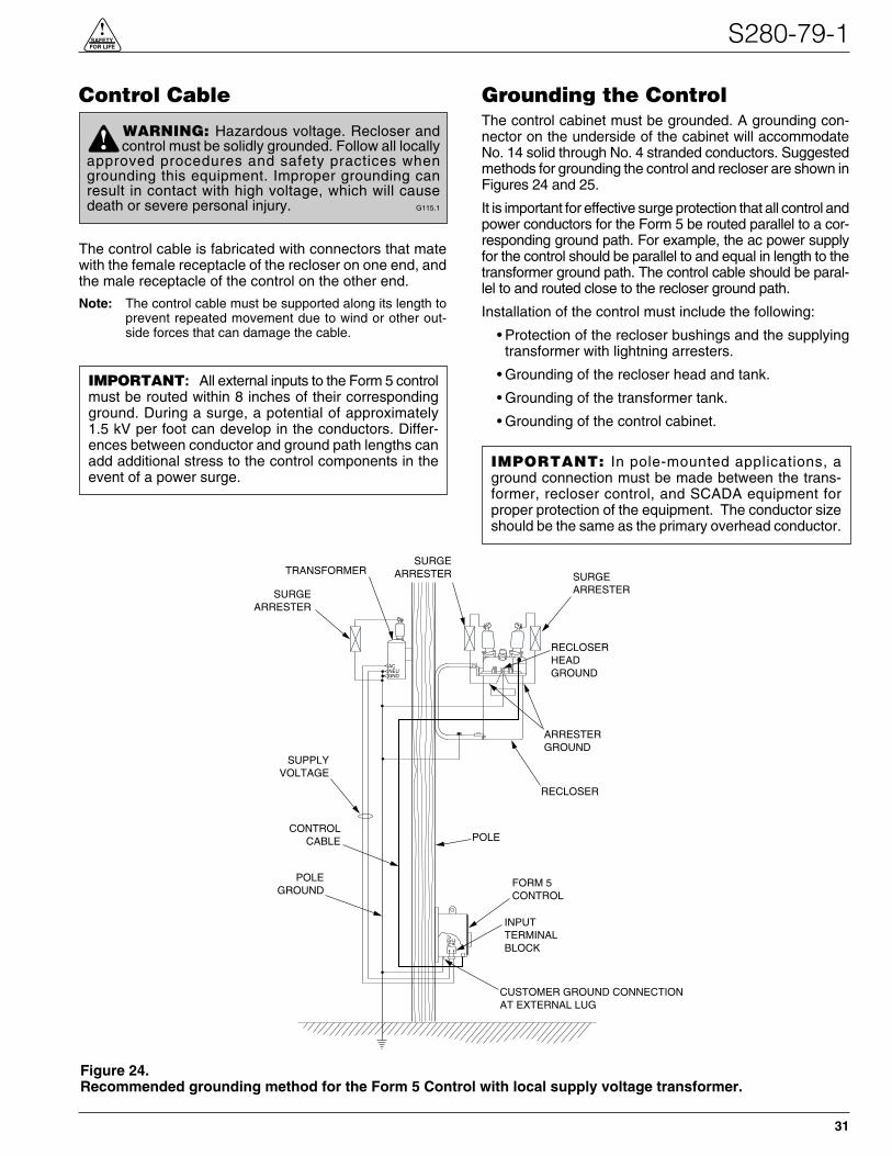
Control Cable
The control cable is fabricated with connectors that matewith the female receptacle of the recloser on one end, andthe male receptacle of the control on the other end.
Note: The control cable must be supported along its length toprevent repeated movement due to wind or other out-side forces that can damage the cable.
Grounding the ControlThe control cabinet must be grounded. A grounding con-nector on the underside of the cabinet will accommodateNo. 14 solid through No. 4 stranded conductors. Suggestedmethods for grounding the control and recloser are shown inFigures 24 and 25.
It is important for effective surge protection that all control andpower conductors for the Form 5 be routed parallel to a cor-responding ground path. For example, the ac power supplyfor the control should be parallel to and equal in length to thetransformer ground path. The control cable should be paral-lel to and routed close to the recloser ground path.
Installation of the control must include the following:
• Protection of the recloser bushings and the supplyingtransformer with lightning arresters.
• Grounding of the recloser head and tank.
• Grounding of the transformer tank.
• Grounding of the control cabinet.
S280-79-1
31
!SAFETYFOR LIFE
WARNING: Hazardous voltage. Recloser andcontrol must be solidly grounded. Follow all locally
approved procedures and safety practices whengrounding this equipment. Improper grounding canresult in contact with high voltage, which will causedeath or severe personal injury. G115.1
!
IMPORTANT: All external inputs to the Form 5 controlmust be routed within 8 inches of their correspondingground. During a surge, a potential of approximately1.5 kV per foot can develop in the conductors. Differ-ences between conductor and ground path lengths canadd additional stress to the control components in theevent of a power surge.
SURGEARRESTER
RECLOSERHEADGROUND
SURGEARRESTERTRANSFORMER
SURGEARRESTER
ARRESTERGROUND
RECLOSER
POLE
SUPPLYVOLTAGE
POLEGROUND
FORM 5CONTROL
CUSTOMER GROUND CONNECTIONAT EXTERNAL LUG
NE
UA
C
GNDNEUAC
INPUTTERMINALBLOCK
CONTROLCABLE
Figure 24.Recommended grounding method for the Form 5 Control with local supply voltage transformer.
IMPORTANT: In pole-mounted applications, aground connection must be made between the trans-former, recloser control, and SCADA equipment forproper protection of the equipment. The conductor sizeshould be the same as the primary overhead conductor.

Installation of the control must include the following:
• Protection of the recloser bushings and the supplyingtransformer with lightning arresters.
• Grounding of the recloser head and tank.
• Grounding of the transformer tank.
• Grounding of the control cabinet.
Kyle Form 5 Microprocessor-Based Recloser Control Installation and Operation Instructions
32
SURGEARRESTER
RECLOSERHEAD
GROUND
*3 WIRE UNGROUNDED SYSTEM** 4 WIRE SYSTEM
* GROUND TIE(#4 CONDUCTOROR LARGER)** NEUTRAL WIRE
SUPPLYVOLTAGE
POLEGROUND
POLE
RECLOSER
POLE
SURGEARRESTER
TRANSFORMER
ARRESTERGROUND
FORM 5CONTROL
ACNEUGRD
NE
UA
C
INPUT TERMINALBLOCK
CONTROL CABLE
SURGEARRESTER
ARRESTERGROUND
CUSTOMER GROUND CONNECTIONAT EXTERNAL LUG
Figure 25.Recommended grounding method for the Form 5 Control with remote supply voltage transformer.
IMPORTANT: All external inputs to the Form 5 controlmust be routed within 8 inches of their correspondingground. During a surge, a potential of approximately1.5 kV per foot can develop in the conductors. Differ-ences between conductor and ground path lengths canadd additional stress to the control components in theevent of a power surge.
IMPORTANT: In pole-mounted applications, aground connection must be made between the trans-former, recloser control, and SCADA equipment forproper protection of the equipment. The conductor sizeshould be the same as the primary overhead conductor.
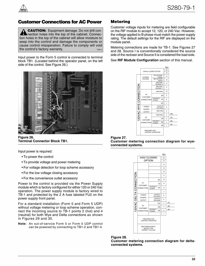
Customer Connections for AC Power
Input power to the Form 5 control is connected to terminalblock TB1. (Located behind the operator panel, on the leftside of the control. See Figure 26.)
Input power is required:
• To power the control
• To provide voltage and power metering
• For voltage detection for loop scheme accessory
• For the low voltage closing accessory
• For the convenience outlet accessory
Power to the control is provided via the Power Supplymodule which is factory configured for either 120 or 240 Vacoperation. The power supply module is factory wired toTB-1 and protected by the 2 A fuse labeled FU2 on thepower supply front panel.
For a standard installation (Form 5 and Form 5 UDP)without voltage metering or loop scheme operation, con-nect the incoming source to TB-1 points 2 (hot) and 4(neutral) for both Wye and Delta connections as shownin Figures 29 and 30.
Note: An out-of-service Form 5 or Form 5 UDP controlcan be powered by connecting to TB1-2 and TB1-4.
MeteringCustomer voltage inputs for metering are field configurableon the RIF module to accept 12, 120, or 240 Vac. However,the voltage applied to B-phase must match the power supplyrating. The default settings for the RIF are displayed on themodule panel.
Metering connections are made for TB-1. See Figures 27and 28. Source I is conventionally considered the sourceside of the recloser and Source II is considered the load side.
See RIF Module Configuration section of this manual.
S280-79-1
33
!SAFETYFOR LIFE
120V
AC
DE
LTA
CO
NN
EC
TIO
N
AC
CUSTOMER
CONNECTIONS
ZØ
YØ
XØSOURCE 2POWER
OUTPUTVOLTAGE
OUTPUTVOLTAGE
*CØ
POWER
SOURCE
OUTPUT
BØ
*AØ
AC
CUSTOMER
CONNECTIONSSOURCE 1POWER
*REQUIRED FOR CONTROL OPERATION
SEE POWER SUPPLYMODULE FOR
CORRECT VOLTAGE
TB1
1
2
3
4
5
6
7
8
9
10
11
12
13
14
CØ
BØ
AØ
240V CLOSINGOPTION 15
16
Figure 28.Customer metering connection diagram for delta-connected systems.
CAUTION: Equipment damage. Do not drill con-nection holes into the top of the cabinet. Connec-
tion holes in the top of the cabinet will allow moisture toseep into the control and damage the components orcause control misoperation. Failure to comply will voidthe control’s factory warranty. T249.0
!
120V
AC
WY
E C
ON
NE
CT
ION
TB1
YØ VOLTAGE120Vac
BØ VOLTAGE120Vac
CLOSINGVOLTAGE
NEUTRALSOURCE 2
NEUTRALSOURCE 1
AC
CUSTOMER
CONNECTIONS
NEUTRAL
ZØ
YØSOURCE 2POWER
XØ
OUTPUTVOLTAGE
NEUTRAL
*NEUTRAL
POWER
SOURCE
OUTPUT
CØ
*BØ
AØ
AC
CUSTOMER
CONNECTIONSSOURCE 1POWER
*REQUIRED FOR CONTROL OPERATION
1
2
3
4
5
6
7
8
9
10
11
12
13
14
240Vac CLOSING OPTION
NEU
CØ
BØ
AØ
15
16
Figure 27.Customer metering connection diagram for wye-connected systems.
Figure 26.Terminal Connector Block TB1.

Kyle Form 5 Microprocessor-Based Recloser Control Installation and Operation Instructions
34
TEST
POSITION
Recloser InterfaceModule
P3
CPU
DISABLED
VOLTAGE
SENSORS
P4
CPU
NORMAL
POSITION
6 (Z)
4 (Y)
2 (X)
5 (C)
3 (B)
1 (A)
BUSHINGNUMBER
PHASE
6 (Z)•
4 (Y)•
2 (X)•
5 (C)•
3 (B)•
1 (A)•
BUSHINGNUMBER
PHASE
CONFIGURED FOR12
VAC120VAC
240VAC
POLARITYDOT
TB1
16
SOURCE AC Power HOT
SOURCE AC Power NEUTRAL
151413121110987654321
P8
Low Voltage Closing AC Power HOT
Low Voltage Closing AC Power NEUTRAL
CustomerConnections
SOURCE AC Power GND
Figure 29.Form 5 and Form 5 UDP Power and Low Voltage Closing customer connections to terminal block TB1 (WyeConnection).
TEST
POSITION
Recloser InterfaceModule
P3
CPU
DISABLED
VOLTAGE
SENSORS
P4
CPU
NORMAL
POSITION
6 (Z)
4 (Y)
2 (X)
5 (C)
3 (B)
1 (A)
BUSHINGNUMBER
PHASE
6 (Z)•
4 (Y)•
2 (X)•
5 (C)•
3 (B)•
1 (A)•
BUSHINGNUMBER
PHASE
CONFIGURED FOR12
VAC120VAC
240VAC
POLARITYDOT
TB1
16
AØ SOURCE AC Power HOT
CØ SOURCE AC Power HOT
151413121110987654321
P8
Low Voltage Closing AC Power HOT
Low Voltage Closing AC Power HOT
CustomerConnections
SOURCE AC Power GND
Figure 30.Form 5 and Form 5 UDP Power and Low Voltage Closing customer connections to terminal block TB1 (DeltaConnection).

Before Placing the Control andthe Recloser into Service
Prior to placing the control and recloser into service, thefollowing installation procedures must be properly com-pleted and verified:
1. Control properly mounted for the installation.
2. Recloser installed according to all locally approvedstandards and practices.
3. Control and recloser properly grounded in accordancewith guidelines in this manual.
4. Control cable properly connected and supported.
5. Control battery connected.
6. Ac power connected to the control (ac power LED indi-cator is ON).
7. All control programming entered and verified byappropriate personnel.
8. Control clock set to the correct time. (Refer to the Set-ting the Control Clock section in Service InformationS280-79-2, Form 5 Recloser Control ProgrammingGuide.)
9. Customer connections for remote and supervisoryoperation checked and completed in accordance withproper shielding and surge protection.
S280-79-1
35
!SAFETYFOR LIFE
CAUTION: Equipment misoperation. Do notconnect this control to an energized recloser
until all control settings have been properly pro-grammed and verified. Refer to the programminginformation for this control. Failure to comply canresult in control and recloser misoperation, equip-ment damage, and personal injury. G110.3
!
WARNING: Hazardous voltage. Recloser andcontrol must be solidly grounded. Follow all
locally approved procedures and safety practiceswhen grounding this equipment. Improper groundingcan result in contact with high voltage, which willcause death or severe personal injury. G115.1
!

Testing an Installed ControlThe following tests to determine initial operation of theForm 5 control can be performed while connected to anoperating recloser. These are the only tests performed onan installed, operating control. All other tests described inthis TESTING AND TROUBLESHOOTING sectionrequire the Form 5 control to be removed from service,connected to a bypassed recloser, or tested at a locationwhere the proper testing equipment is available.
1. Turn on the front panel display press theCHANGE/LAMP TEST button on the control frontpanel.
2. Scroll through the LCD display messages asdescribed in the LCD Display Messages section ofthese instructions. (See Form 5 Control Front Panelsection of this manual.)
Check the operational values for currents, voltages,and other metering information.
3. Check that the LED for ac power is illuminated on thecontrol front panel. This indicates the presence of acpower.
4. Test battery operation using the procedures describedin the Battery Test Procedure section of theseinstructions.
Check CPU StatusCheck the operating status CPU module. Open the cabi-net door and locate the LED indicator (see Figure 31).
The LED indicator on the CPU module should flash at arate of one flash per second for normal operation.
Testing With Type MET Tester
The Kyle Type MET Electronic Recloser Control Tester isused for testing the Form 5 control. See Figure 32.
The MET Tester is completely self-contained, includes allnecessary metering and interconnecting cables, and iscapable of performing all required checks and tests froma simple verification of operation to a complete verificationof all operating parameters. Refer to Service InformationS280-76-1 Type MET Electronic Recloser Control TesterInstructions for proper setup and use of the MET tester.
Kyle Form 5 Microprocessor-Based Recloser Control Installation and Operation Instructions
36
IMPORTANT: The Form 5 recloser control can betaken out of service for testing and placed back into ser-vice without de-energizing its recloser and interruptingthe system. However, during the time the control is outof service, the recloser is inoperative.
TESTING AND TROUBLESHOOTING
CAUTION: Equipment misoperation. Do notconnect this control to an energized recloser
until all control settings have been properly pro-grammed and verified. Refer to the programminginformation for this control. Failure to comply canresult in control and recloser misoperation, equip-ment damage and personal injury. G110.3
!
Figure 31.Form 5 control CPU module.
970022KM
CPU Module(Computer Processing Unit)
CPU Module LED Indicator
Figure 32.Kyle Type MET electronic recloser control tester.
010028KM
IMPORTANT: The Form 5 DC NOVA control cannotbe tested with the standard Kyle MET Tester. A junc-tion box accessory for the MET tester is available fortesting the Form 5 DC NOVA control.
IMPORTANT: When the control is open and currentis present, the Trip Fail detection circuit in the Form 5Control will activate when the Kyle Type MET TesterCALIBRATE switch is ON. Depress and hold theRESET TARGET keypad on the control for three sec-onds to reset the condition.
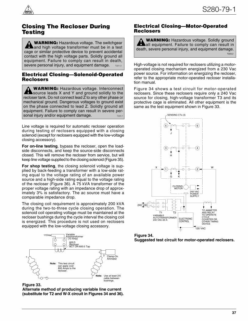
Closing The Recloser DuringTesting
Electrical Closing—Solenoid-OperatedReclosers
Line voltage is required for automatic recloser operationduring testing of reclosers equipped with a closingsolenoid (except for reclosers equipped with the low-voltageclosing accessory).
For on-line testing, bypass the recloser, open the load-side disconnects, and keep the source-side disconnectsclosed. This will remove the recloser from service, but willkeep line voltage supplied to the closing solenoid (Figure 35).
For shop testing, the closing solenoid voltage is sup-plied by back-feeding a transformer with a low-side rat-ing equal to the voltage rating of an available powersource and a high-side rating equal to the voltage ratingof the recloser (Figure 36). A 75 kVA transformer of theproper voltage rating with an impedance drop of approx-imately 3% is satisfactory. The ac source must have acomparable impedance drop.
The closing coil requirement is approximately 200 kVAduring the two-to-three cycle closing operation. Thesolenoid coil operating voltage must be maintained at therecloser bushings during the cycle interval the closing coilis energized. This procedure is not used on reclosersequipped with the low-voltage closing accessory.
Electrical Closing—Motor-OperatedReclosers
High-voltage is not required for reclosers utilizing a motor-operated closing mechanism energized from a 230 Vacpower source. For information on energizing the recloser,refer to the appropriate motor-operated recloser installa-tion manual.
Figure 34 shows a test circuit for motor-operatedreclosers. Since these reclosers require only a 240 Vacsource for closing, high-voltage transformer T3 and itsprotective cage is eliminated. All other equipment is thesame as the test equipment shown in Figure 33.
S280-79-1
37
!SAFETYFOR LIFE
WARNING: Hazardous voltage. Solidly groundall equipment. Failure to comply can result in
death, severe personal injury, and equipment damage.T223.2
!
Figure 34.Suggested test circuit for motor-operated reclosers.
65
43
21
ELECTRONICCONTROL
J
G K
H
X W
240 VACPOWERSUPPLY
CLOSINGMOTOR
T1 T2
240 VAC
VARIABLEAUTOTRANSFORMER240 VAC-20 A
120 VAC
TO AMMETERAND RELAYTO OPERATECYCLECOUNTER OROTHER TIMINGDEVICE
SENSING CTs (3)
WARNING: Hazardous voltage. Interconnectsource leads X and Y and ground solidly to the
recloser tank. Do not connect lead Z to any other phase ormechanical ground. Dangerous voltages to ground existon the phase connected to lead Z. Solidly ground allequipment. Failure to comply can result in severe per-sonal injury and/or equipment damage. T224.1
!
Figure 33.Alternate method of producing variable line current(substitute for T2 and W-X circuit in Figures 34 and 36).
600:5RecloserBCT ON 600:5 Tap
Note: This test circuit can apply over 800 Amps to the recloser.
Note: Use at least 2/0 cable between bushings.
21
115Vac VariableAutotransformer (10 Amp)
Clamp-OnAmmeter
WARNING: Hazardous voltage. The switchgearand high voltage transformer must be in a test
cage or similar protective device to prevent accidentalcontact with the high voltage parts. Solidly ground allequipment. Failure to comply can result in death,severe personal injury, and equipment damage. T221.3
!

Kyle Form 5 Microprocessor-Based Recloser Control Installation and Operation Instructions
38
3
6
4
T3Y
H
X
Z
VOLTAGE RATING OFRECLOSER CLOSINGSOLENOID COIL
SENSING C-T's (3) CLOSINGSOLENOIDCONTACTOR
ROTARYSOLENOID
MAINCONTACTS (S)
G K
A B
E F
TO240 OR480 VACSOURCE
TO240 VACSOURCE
CLOSINGSOLENOIDCOIL
TRIPSOLENOID
CONTROLCABLE RECEPTACLE
W
ELECTRONICCONTROL
TOAMMETER AND RELAY TOOPERATE CYCLE COUNTEROR OTHER TIMING DEVICE
120 VACVARIABLEAUTOTRANSFORMER240 VAC20 AMPS
T2
1 2
5
J
Figure 36.Suggested test circuit for solenoid-closing reclosers.
5 6
3 4
1 2
C
B
A
BYPASS SWITCHES(CLOSED)
SOURCE SIDEDISCONNECT SWITCHES(CLOSED)
LOAD SIDEDISCONNECT SWITCHES(OPEN)
CLO
SIN
GC
OIL
LOA
D
SO
UR
CES
OU
RC
E
LOA
D
Figure 35.Closing source-side switches of a bypassed “on-line” recloser provides closing solenoid power for automaticoperation during testing.

Manual Closing—Solenoid-OperatedReclosers
If high voltage for operating the closing solenoid is notavailable, manual closing can be substituted for electricalclosing. However, not all control settings can be checkedsince manual closing is not synchronized with the closingcoil control circuit in the control.
To manually close the recloser:
1. Remove the closing tool port cover and gasket fromthe side of the recloser head casting.
2. Insert the tee-handled tool (available as an accessory)into the port, engaging the pin on the closing shaft(Figure 37).
3. Close the recloser by placing the yellow operatinghandle (located under the sleethood) into the up orCLOSED position and turning the closing tool one-quarter turn clockwise.
4. After each trip operation, about 1/2 second elapseswhile the closing solenoid plunger is moving upward toreset the main toggle latch.
5. After the main toggle latch resets, the recloser can beclosed again by operating the manual closing tool.
6. Replace the gasket and port cover on the recloserhead after testing has been completed.
Remove the Form 5 Control fromService
1. Enable GND TRIP BLOCKED to allow for ground tripto be disabled when re-energized.
A. Press the CHANGE/LAMP TEST key on the Oper-ator Panel to enter the CHANGE mode.
Note: The LCD Display Screen will indicate the amountof time available in CHANGE mode to make achange.
B. Depress the GND TRIP BLOCKED key.
Note: After the GND TRIP BLOCKED key isdepressed, the red LED indicator will illuminateto indicate GROUND TRIP BLOCKED is active.
2. Unplug the control battery.
3. Remove control ac sensing and power connectionsfrom the control using a separate disconnect switch.
5. Disconnect control cable from the control.
Note: If the control is connected to a control-poweredNOVA recloser, wait approximately 10 minutes forthe 53 Vdc to dissipate from the control cable beforetouching the pins in the male end.
6. Disconnect the ground from the control.
S280-79-1
39
!SAFETYFOR LIFE
WARNING: Explosion Hazard. Excessive Con-tact Arcing. Do not use the manual closing tool to
close an oil-insulated energized recloser. Closing anenergized oil-insulated recloser with a manual closingtool can cause excessive contact arcing, rapid build-upof gas within the equipment, and possible explosionthat can cause death, severe personal injury, andequipment damage. T203.2
!
CAUTION: Equipment damage. Do not turn the man-ual closing tool more than one-quarter turn clockwise.Forcing the tool beyond the mechanism stop may shearthe pin on the closing shaft of the recloser. T222.0
Figure 37.Using a manual closing tool to operate the recloser.
82284KMA-F
IMPORTANT: Disconnect switches for ac sensingand power connections are necessary to isolate theForm 5 Recloser Control for testing and servicing.
CAUTION: Personal Injury. Allow approxi-mately 10 minutes for the 53 Vdc to dissipate from
the 19-pin control cable connected to a control-pow-ered NOVA recloser after the power to the recloser hasbeen disconnected. Touching any of the 19 pins in themale end of the control cable plug prior to the dissipa-tion of the 53 Vdc can result in personal injury or equip-ment damage. T302.0
!
WARNING: Hazardous voltage. If the recloseris energized while the control cable is discon-
nected, the CT secondaries can generate high volt-ages. Contact with high voltage can cause severepersonal injury or death. T204.2
!

Kyle Form 5 Microprocessor-Based Recloser Control Installation and Operation Instructions
40
Return the Form 5 Control to Service
After the required work is completed, disconnect the con-trol from the test set and follow this procedure to return thecontrol to service:
1. While still in the service shop, appropriate personnelmust verify that all control settings are correct.
2. Reconnect the control cable to the control.
3. Control cable properly connected and supported.
4. Plug in the control battery.
5. Apply ac power to the control.
6. Disable GND TRIP BLOCKED.
A. Press the CHANGE/LAMP TEST key on the Oper-ator Panel to enter the CHANGE mode.Note: The LCD Display Screen will indicate the amount
of time available in CHANGE mode to make achange.
B. Depress the illuminated GND TRIP BLOCKED key.Note: After the GND TRIP BLOCKED key is
depressed, the red LED indicator will no longerbe i l luminated indicating GROUND TRIPBLOCKED is not active.
7. Reset the control clock after ac power has been re-applied. Refer to Setting the Control Clock section inService Information S280-79-2, Form 5 RecloserControl Programming Guide.
Replacement Kits
Replacement kits for the Kyle Form 5 Control are avail-able through the factory Service Department. To orderthese kits, refer to the Replacement Parts price list for cat-alog numbers and pricing. Contact your Cooper PowerSystems representative for additional information andordering procedures.
Factory-Authorized ServiceCentersFactory-authorized service centers are located through-out the continental United States to provide maintenance,repair, and testing services for Kyle controls andreclosers. For further information, contact your CooperPower Systems representative.
Factory Maintenance ClassesThe factory service department offers a basic testing andtroubleshooting course for the Form 5 Microprocessor-Based Electronic Recloser Control and Reclosers. Thiscourse, taught by experienced service technicians, is heldat the factory‘s in-house training facility. For additionalinformation, contact your Cooper Power Systems repre-sentative.
Type MET Recloser Control TesterA 30-minute video cassette program, KSPV7 Kyle® TypeMET Electronic Recloser Control Tester Operation andTesting Procedures is available as a supplemental train-ing aid for service personnel.
CAUTION: This equipment requires routineinspection and maintenance to ensure proper
operation. If it is not maintained, it can fail to operateproperly. Improper operation can cause equipmentdamage and possible personal injury. G105.1
!
ADDITIONAL INFORMATION
CAUTION: Equipment misoperation. Do notconnect this control to an energized recloser
until all control settings have been properly pro-grammed and verified. Refer to the programminginformation for this control. Failure to comply canresult in control and recloser misoperation, equip-ment damage, and personal injury. G110.3
!
KA2048-415 Rev. 01
KMG12/02
P.O. Box 1640Waukesha, WI 53187www.cooperpower.com
© 2002 Cooper Power Systems, Inc.Kyle® is a registered trademark of Cooper Industries, Inc.
!SAFETYFOR LIFE


![Finale 2006 - [S280 Glory to God Brass BEV]cuthbertpraise.com/files/S280_SCORE.pdfGlory to God (Brass Ensemble Version) S280 Canticle 20 ©2006 CuthbertPraise! #S280 Episcopal Hymnal](https://img.pdfslide.us/doc/110x75/60056d6ed54e1c4229237c69/finale-2006-s280-glory-to-god-brass-bev-glory-to-god-brass-ensemble-version.jpg)