Embed Size (px)
Citation preview

KY DIVISION OF
ABANDONED MINE
LANDS
TECHNICAL SPECIFICATIONS
Updated Through July 2017
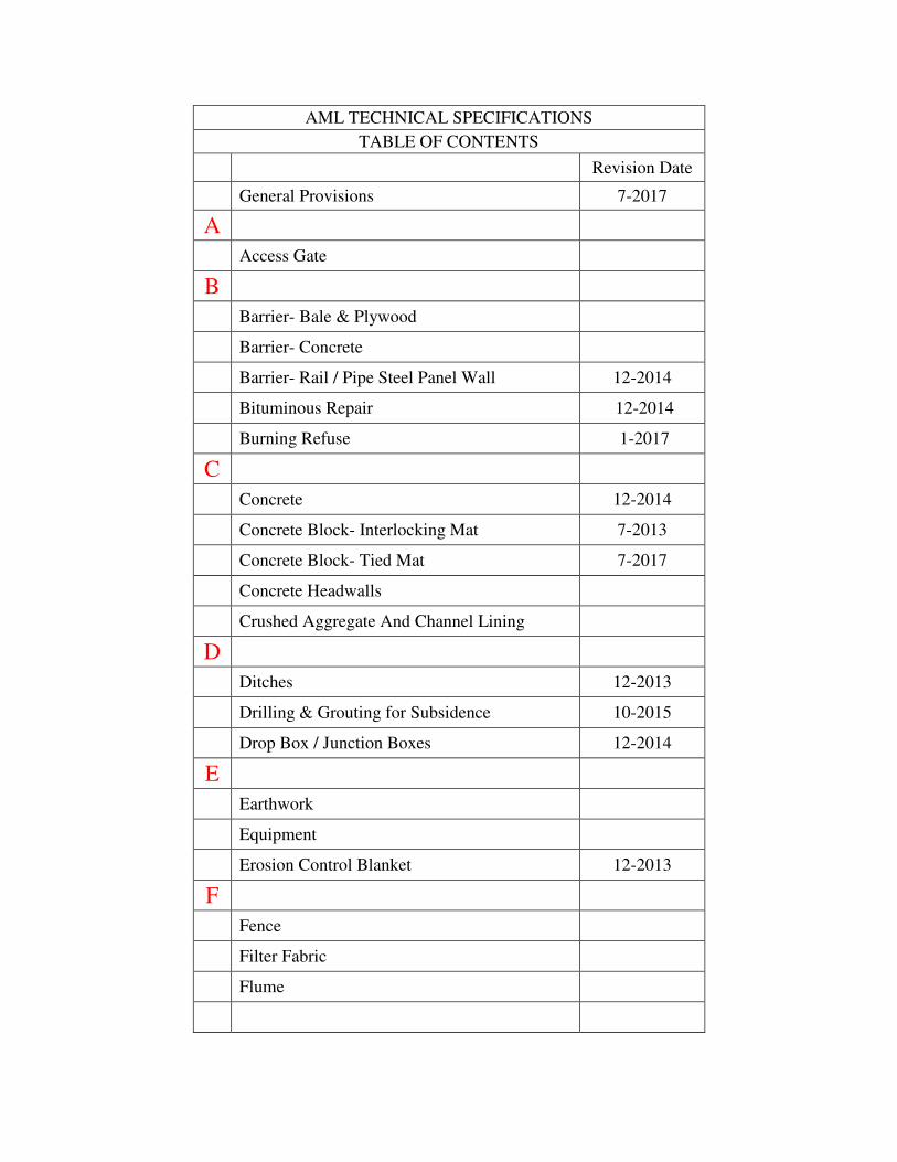
AML TECHNICAL SPECIFICATIONS
TABLE OF CONTENTS
Revision Date
General Provisions 7-2017
A
Access Gate
B
Barrier- Bale & Plywood
Barrier- Concrete
Barrier- Rail / Pipe Steel Panel Wall 12-2014
Bituminous Repair 12-2014
Burning Refuse 1-2017
C
Concrete 12-2014
Concrete Block- Interlocking Mat 7-2013
Concrete Block- Tied Mat 7-2017
Concrete Headwalls
Crushed Aggregate And Channel Lining
D
Ditches 12-2013
Drilling & Grouting for Subsidence 10-2015
Drop Box / Junction Boxes 12-2014
E
Earthwork
Equipment
Erosion Control Blanket 12-2013
F
Fence
Filter Fabric
Flume
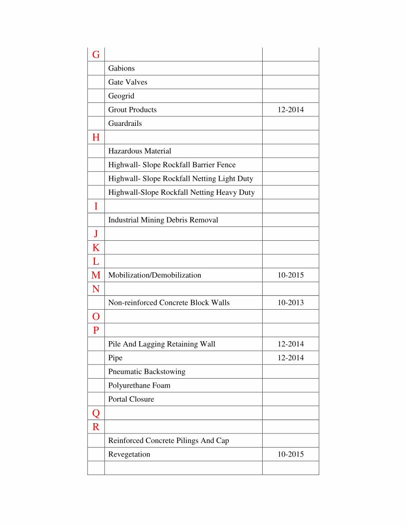
G
Gabions
Gate Valves
Geogrid
Grout Products 12-2014
Guardrails
H
Hazardous Material
Highwall- Slope Rockfall Barrier Fence
Highwall- Slope Rockfall Netting Light Duty
Highwall-Slope Rockfall Netting Heavy Duty
I
Industrial Mining Debris Removal
J
K
L
M Mobilization/Demobilization 10-2015
N
Non-reinforced Concrete Block Walls 10-2013
O
P
Pile And Lagging Retaining Wall 12-2014
Pipe 12-2014
Pneumatic Backstowing
Polyurethane Foam
Portal Closure
Q
R
Reinforced Concrete Pilings And Cap
Revegetation 10-2015
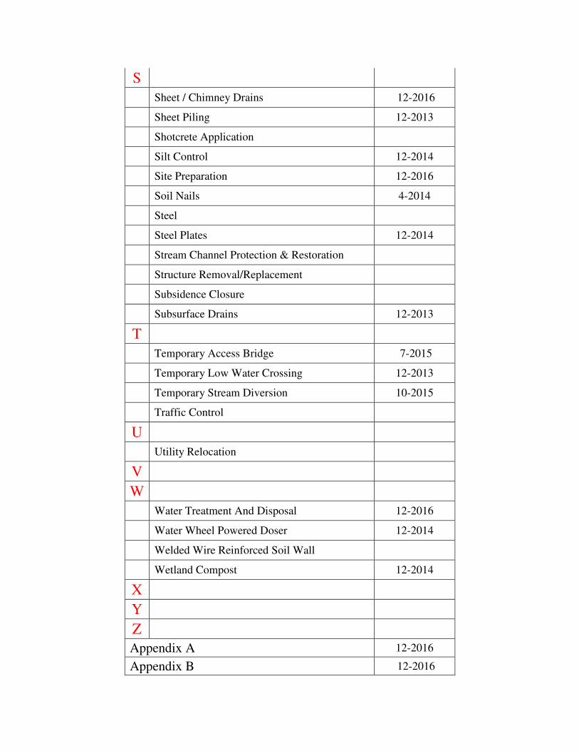
S
Sheet / Chimney Drains 12-2016
Sheet Piling 12-2013
Shotcrete Application
Silt Control 12-2014
Site Preparation 12-2016
Soil Nails 4-2014
Steel
Steel Plates 12-2014
Stream Channel Protection & Restoration
Structure Removal/Replacement
Subsidence Closure
Subsurface Drains 12-2013
T
Temporary Access Bridge 7-2015
Temporary Low Water Crossing 12-2013
Temporary Stream Diversion 10-2015
Traffic Control
U
Utility Relocation
V
W
Water Treatment And Disposal 12-2016
Water Wheel Powered Doser 12-2014
Welded Wire Reinforced Soil Wall
Wetland Compost 12-2014
X
Y
Z
Appendix A 12-2016
Appendix B 12-2016
Ver. 7-2017 General Provisions- 1
GENERAL PROVISIONS
1. SCOPE
These specifications are written to the CONTRACTOR. The sentences which direct the CONTRACTOR to perform work are written in the active voice-imperative mood. These directions to the CONTRACTOR are written as commands. In the imperative mood, the subject “the CONTRACTOR” is understood. All other requirements to be performed by others have been written in the active voice. Sentences written in the active voice identify the party responsible for performing the action. Certain requirements of the CONTRACTOR may also be written in active voice, rather than active voice-imperative mood. Sentences that define terms, describe a product or desired result, or describe a condition that may exist are not written in either the active voice or the imperative mood. These types of sentences that describe a condition use verbs requiring no action. Each Technical Specification defines scope of work
and certain aspects of that work. Any work discussed in a Technical Specification but not
listed as a bid item shall be considered incidental to the Technical Specifications unless
otherwise directed by the ENGINEER.
When any Technical Specifications refers to a specification outside of these documents it
shall mean the current edition unless stated otherwise in the Contract Documents.
2. GENERAL DEFINITIONS
The following definitions clarify, supplement and/or amend those provided in APPENDIX C- “FINANCE and ADMINISTRATION CABINET GENERAL CONDITIONS.” 2.1. Kentucky Division of Abandoned Mine Lands: may also be referred to in these Technical Specifications as “DAML” or “AML” and all refer to the same entity.
2.2. Design Drawings, Drawings, Standard Details and Plans: Are synonymous and all refer to the set of design drawings or standard details as published by AML.
2.3. ENGINEER: Shall mean a DAML representative who is a Professional Engineer licensed in the Commonwealth of Kentucky and has administrative and engineering oversight authority for the project. This individual shall be identified at the Pre-Construction Conference. If the ENGINEER delegates authority to other personnel this will be stated in writing and provided to the Technician, Supervisor, Resident Inspector and Contractor.
2.4. TECHNICIAN: Shall mean the DAML representative who gives technical advice for the project to which they are assigned. 2.5. SUPERVISOR or FIELD OFFICE SUPERVISOR: Shall mean the DAML representative who is the direct supervisor of the Resident Inspector.
Ver. 7-2017 General Provisions- 2
2.6 RESIDENT INSPECTOR or INSPECTOR: Shall mean the DAML representative who is assigned to monitor the daily construction activities for the project to which they are assigned.
2.7 CONTRACTOR: Shall refer to the prime contractor who has obtained the contract and is responsible for the execution of the contract.
2.8. SUBCONTRACTOR: Shall refer to a subcontractor reporting to the CONTRACTOR. 2.9. CONTRACT PERIOD: Shall be defined as that time required for completion of this reclamation project in accordance with the existing Drawings and Specifications including any extensions approved by official change orders. This definition augments but does NOT amend the General Conditions in Appendix C.
2.10. BMP: Shall refer to the Division of Abandoned Mine Lands Erosion and Sediment Control Best Management Practices (BMP) Plan in Appendix B. 3. QUANTITY UNIT DEFINITIONS
3.1. Lump Sum (LS): When this term is used as an item of payment, it shall be inferred that the complete structure, structural unit, or element of work is specified as the unit measurement. As such, it will be construed to include all necessary fittings and accessories, labor, equipment, and other incidentals required for installation. No final measurement will be made.
3.2. Each: The definition shall be the same as for Lump Sum with the exception that more than one of the referenced item may be used and that final measurement will be the actual number of the item that is installed and accepted by the ENGINEER. 3.3. Plan (or Design) Quantity (PQ): When the "Plan Quantity" for a specific portion of the Project is designated as the method of payment in the Contract Documents, it shall be the quantity for which payment will be made. An exception will be made in the event of significant computational error or if dimensions shown in the Drawings are revised by the ENGINEER.
3.4. Unit Price (UP): When "Unit Price" quantities for a specific portion of the Project are designated in the Contract Documents as the pay quantity, actual quantities for such specified portion will serve as the basis for payment. Actual quantities shall be determined by the differences between measurements taken before and after construction.
3.5 Actual Cost Units (ACU): When “Actual Cost Units” are designated as the method of payment, it shall be only for those documented costs directly associated with the completion of the specific work item that has been designated for this type of payment method. The CONTRACTOR shall supply the ENGINEER with all of the necessary documents supporting costs incurred by the CONTRACTOR in order to qualify for payment. Actual Cost will be paid for and measured in “Actual Cost Units (ACU)” and each unit shall equal the sum of $1.00.
Ver. 7-2017 General Provisions- 3
4. MEASUREMENT DEFINITIONS
All work completed under this Contract will be and/or has been measured by the ENGINEER according to United States standard measure. The following terms apply: 4.1. Linear Feet (LF): All items measured by the linear foot, such as pipe, guardrail, drains, etc., will be measured along or parallel to the baseline and/or centerline upon which such items are placed or constructed, unless specified otherwise on the Drawings or in subsequent sections of the Technical Specifications. No allowances will be made on installed items for fittings or laps at connections. (When used, the term "station" will be 100 linear feet measured horizontally.)
4.2. Areas and Volumes: Determination of Areas and Volumes shall utilize standard surveying techniques. The planimeter shall be considered an instrument of sufficient precision adapted to the measurement of areas. Areas may also be determined by using aerial photography and computer programs such as AutoCAD or ARC GIS. Field measurements may also be used if stated in the Bid Item Description. In computing volumes of excavation and embankments, the average-end-area method will be used.
4.3 Surface Area: Surface area, when used in these specifications, shall mean the actual area of expanded surface taking into account the configuration and slope of the item of work being measured, i.e., slope distances.
4.4. Horizontal Plane Area: Horizontal plane area, when used in these specifications, shall mean the area of projection of the surface area on a horizontal plane.
4.5. Weight: When weight is used as the measurement standard, certified tickets, invoices, or tags for such items must be furnished to the ENGINEER. (When used, the term "ton" will mean 2,000 pounds avoirdupois.) 5. CONTRACT DOCUMENTS ORDER OF PRIORITY
In the event of conflicts between the various elements of these Contract Documents, the order of precedence shall be as follows:
1. Addendum 2. AML Contractual Obligations & Requirements (includes Bid Item Description) 3. AML Special Conditions/Notes 4. AML Design Drawings/Plans 5. AML Technical Specifications 6. AML Standard Details 7. Bid Schedule
Ver. 7-2017 General Provisions- 4
6. SUBCONTRACTING
The division of the Technical Specifications is done for convenience of reference and is not intended to control the CONTRACTOR in dividing work among SUBCONTRACTORs or to limit the scope or type of work performed by any trade. If the CONTRACTOR intends to subcontract portions of the work, this intent shall be indicated and the areas identified in the space provided in the Form of Proposal. After the Award of Contract, do not modify and/or add additional subcontracting without prior written approval of the ENGINEER. Subcontracting of the work or assignment of the contract shall not release the CONTRACTOR of his liability under the contract and bond. Provide and maintain the proper facilities, clerical personnel and field superintendents for proper management and coordination of SUBCONTRACTORS and the CONTRACTOR’S own forces, as well as for providing and maintaining direct lines of communication between the CONTRACTOR and the ENGINEER. The ENGINEER shall not be required to deal directly with SUBCONTRACTORS. Failure to provide adequate qualified field management services will be cause for termination of the contract. 7. FUND AUTHORIZATION
Funds for this Project have been authorized by the U.S. Department for Interior, Office of Surface Mining, under the provisions of Title IV of Public Law 95-87. Funds are secured by a U.S. Treasury Letter of Credit. On the basis of an approved invoice amount, the DAML will coordinate the release of federal funds and the payment to the CONTRACTOR by the COMMONWEALTH. All payments shall be issued by the Kentucky State Treasurer. 8. SUBSURFACE INFORMATION
Site-specific geotechnical information is generally limited. Without regard to the materials encountered, all excavation shall be unclassified. It shall be strictly understood that any reference to rock, soil, or any other material in the Drawings or in the Technical Specifications, whether in numbers, words, letters, or lines, is solely the COMMONWEALTH'S information and is not to be taken as an indication of classified excavation or the quantity of rock, soil, or any other material involved. 9. EXISTING CONDITIONS & REPAIR OF DAMAGE
DAML will document pre-project condition of the property(s) within the project area using video and photography, however, the CONTRACTOR should document any existing damage themselves. Any damage that is not documented prior to the work may be considered as caused by the CONTRACTOR and may require correction. Any damage done to structures, fills, roadways, or other property(s) not directed as part of the project by the ENGINEER or caused by neglect on the CONTRACTOR’S part shall be repaired at the CONTRACTOR'S expense before final payment is made. In the event such damage
Ver. 7-2017 General Provisions- 5
occurs at the direction of the ENGINEER, payment will be made at the bid unit price for such item or in a lump sum as agreed to by both parties. 10. PROPERTY OWNER CONSIDERATION (Revised 7-2013)
Authority to enter and reclaim private property is obtained by written consent of the owner and is pursuant to Title IV of the Surface Mining Control and Reclamation Act of 1977, 30 U.S.C. 1231, and KRS 350.150. The COMMONWEALTH, in complying with these provisions, does not obtain title or rights to any property within the project area. All rights to property and existing materials within the project area will therefore remain the property of the owner. Materials having a salvage value (coal, oil, gas, precious metals, timber, topsoil, etc.) shall remain the property of the owner. Salvageable material (excluding coal, refuse, & other mineral resources) rejected by the owner shall become the responsibility of the CONTRACTOR to dispose of in a proper manner subject to the approval of the ENGINEER. During the construction process it may happen that property monuments or property fence may be disturbed. Prior to disturbance, the CONTRACTOR shall give DAML at least 2-week notice to allow DAML to reference said monument(s). If the CONTRACTOR disturbs the monument(s) without providing a 2-week notice to DAML, then the CONTRACTOR shall be responsible for having the monuments reestablished by a Professional Land Surveyor licensed/registered in the Commonwealth of Kentucky at the CONTRACTOR’s expense. DAML referenced monuments will be reestablished after construction; however, DAML will not certify the monuments as an official property corner. 11. ALTERNATIVE / EQUIVALENT PRODUCTS & MATERIALS
The use of alternative/equivalent products, materials, and systems shall be approved in writing by the DAML design engineer in conjunction with the DAML construction oversight engineer prior to ordering or using the product/materials. The CONTRACTOR must submit a written request to use alternative/equivalent products, materials, and systems along with all certifications, testing results, specifications, and any other information required by DAML. The ENGINEER may require additional testing. Such testing shall be paid for by the CONTRACTOR. In certain instances the ENGINEER may require the CONTRACTOR to guarantee the product for a period of time to be stated in writing and incorporated into the contract. DAML will provide written approval or disapproval. The use of alternative products, materials, systems may require alterations to the design plans by a professional engineer (licensed & registered in Kentucky) employed by the product supplier or CONTRACTOR. These revised plans shall be reviewed and approved by the ENGINEER.
12. BLASTING RESTRICTIONS
No blasting shall be permitted without prior approval. In the event blasting is proposed the CONTRACTOR shall prepare documentation outlining the blasting plan and requesting approval. The request must be made and approved prior to any blasting.
Ver. 7-2017 General Provisions- 6
13. COAL REMOVAL
No coal, refuse, or other mineral resources shall be removed from either the project area or from the construction & waste areas in conjunction with this contract. 14. PRE-BID CONFERENCE A Pre-Bid Conference will be held as specified by the bid documents. The Pre-Bid Conference should be attended by representatives of the COMMONWEALTH (i.e. representatives of AML) and Contractors interested in bidding on the Project. No individual site visits by the
Contractor(s) or representatives of the COMMONWEALTH shall be held.
15. METHOD OF BIDDING
The Bidder must use the bidding documents furnished by the COMMONWEALTH. All data and other information requested must be supplied. The bidder must submit unit price bids on all items contained on the Bid Schedule, regardless of whether the individual items of work are to be let by "Unit Price", "Lump Sum", “Actual Cost”, or "Plan Quantities”. The submission of a bid will be construed as evidence that a site visit and examination have been made, that the bidder is thoroughly familiar with, understands, and agrees to all terms and intents of the Contract Documents, and that any conflicts within the documents or between the documents and other written instructions or verbal statements have been resolved to the satisfaction of the bidder. Claims for labor, equipment, materials, or other costs required due to difficulties which could have been foreseen had an adequate examination of the site been made, the Contract Documents read thoroughly and clarification sought will not be recognized. 16. AWARD OF CONTRACT
Award of Contract will be made as determined by the Finance and Administration Cabinet. The unit prices will control the extensions and totals. Any obvious case of unbalanced bidding will be considered sufficient grounds for rejection of the entire bid. The COMMONWEALTH reserves the right to reject any and all bids if it is deemed to be in the best interest of the COMMONWEALTH. 17. PRE-CONSTRUCTION CONFERENCE (Revised 7-2017)
Following the signing of the Contract Documents and prior to the actual beginning of the construction, a pre-construction conference will be held. Representatives of the DAML, the CONTRACTOR, including any SUBCONTRACTOR(s), the Finance and Administration Cabinet, as well as other interested agencies and parties may be present to discuss the time and sequence for construction, methods and plans of operations, payment and other relevant questions. The time and locations of this meeting will be the responsibility of the DAML in consultation with the other parties.
Ver. 7-2017 General Provisions- 7
The CONTRACTOR shall be prepared to present to the ENGINEER a schedule of construction for approval. Progress schedules shall indicate the estimated periods during which the CONTRACTOR will be actively working on various portions of the project to assure completion on schedule. The schedule may be adjusted by the ENGINEER if deemed necessary to insure individual project completion. 18. WORKING HOURS & EXCUSED WORK DAYS
Critical working hours on this project shall be from 8:00 a.m. to 4:30 p.m., Monday through Friday, for the duration of the construction project. Critical work items, as determined in writing by the ENGINEER, will be scheduled for work during these times. The ENGINEER may approve Critical Work, at his sole discretion, at other times when the performance of such work is in the best interest of the COMMONWEALTH. If the CONTRACTOR performs Critical Work outside working hours or without prior approval of the ENGINEER, the ENGINEER is under no obligation to accept or pay for such work. Emergency work, such as necessary pumping, fire quenching, smoke/fume control, or utility repair shall be completed as required, but the CONTRACTOR shall provide the ENGINEER as much notice as is practicable. Non-critical work, as determined by the ENGINEER may be completed between the hours of 7:00 a.m. - 7:00 p.m., Monday through Saturday, if requested by the CONTRACTOR and approved by the ENGINEER. The ENGINEER will provide a Resident Inspector during critical working hours. The Resident Inspector will keep a record and determine working or not working days. These will be recorded as excused/non-excused work days. Holiday’s recognized by the COMMONWEALTH, weekends, and official temporary shutdowns are not included in the excused/non-excused critical work day totals. At the end of the project the net excused days will be calculated by subtracting the non-excused days from the excused days that may be added to the contract by the ENGINEER. The ENGINEER is under no obligation to extend the contract due to weather related/excused days. 19. TEMPORARY SHUTDOWNS
The CONTRACTOR may request, in writing, for an extended construction "shutdown" due to circumstances beyond the CONTRACTOR'S control. Prior to the ENGINEER approving the
request the CONTRACTOR shall be required to dress all disturbed areas to a reasonable
smooth configuration, protect disturbed areas with temporary mulch and cover crop,
install temporary diversion ditches, and additional erosion and sediment control measures. During an approved shutdown the CONTRACTOR shall still maintain sediment control structures. The COMMONWEALTH shall incur no additional costs for such work, or for the expense of demobilization or remobilization.
Ver. 7-2017 General Provisions- 8
20. PROJECT INSPECTION/CONTROL OF WORK (Revised 7-2017)
Inspection of all construction features (i.e. quality control) shall be performed by; Division of Abandoned Mine Lands
300 Sower Blvd.
Frankfort, Kentucky 40601
The ENGINEER and his representatives shall at all times have ready access to the project area. The control of work shall be as follows: 20.1. Authority of the ENGINEER: The ENGINEER will decide all questions regarding the quality and acceptability of materials furnished, work performed, and the rate of progress of the work; all interpretation of the Plans and Specifications; the acceptable fulfillment of the Contract and all changes to the documents including approval of all change orders in accordance with acceptable policies now in place. The ENGINEER will, in writing, suspend the work, wholly or in part when the CONTRACTOR fails to correct conditions unsafe for the workmen or the general public; for failure to carry out Contract provisions; for failure to carry out orders; for periods of unsuitable weather; for conditions unsuitable for the prosecution of the work; or for any other condition or reason determined to be in the public interest. To prevent misunderstanding, the ENGINEER, within a reasonable time, will decide any and all questions concerning the quality and acceptability of materials furnished, work performed, and as to the manner of performance and rate of progress of the work. The ENGINEER will decide all questions concerning the interpretation of the Contract relating to the work, and all questions concerning the acceptable fulfillment of the work performed by the CONTRACTOR. The ENGINEER will determine the quantity and quality of the several kinds of work performed and materials furnished that the COMMONWEALTH will pay for under the Contract, and such decision and estimate will be final and conclusive. In case any question arises, the Engineer’s estimate will be a condition precedent to the right of the CONTRACTOR to receive any money due under the Contract. The ENGINEER will answer any questions as to the meaning of the Contract, or any obscurity as to the wording of the Contract and give all directions and explanations necessary to make definite any of the provisions of the Contract, or necessary to complete or give them due effect. The CONTRACTOR may request and the ENGINEER will provide written instructions concerning any significant item. At any time within the project the ENGINEER may require the CONTRACTOR to present a written updated schedule of construction and to meet onsite or at an DAML Office to discuss the project status and make adjustments to the construction schedule as needed to complete the project. 20.2. Authority of Supervisor: Supervisors shall make sure that the contract documents are being enforced. However, supervisors may not make any changes to the contract documents
without written approval from the ENGINEER but can recommend changes to the
Ver. 7-2017 General Provisions- 9
ENGINEER. The supervisor will be responsible for the inspector’s work and conduct. The supervisor shall check all work/documentation generated by the inspector and certify the work/documentation. Supervisors shall certify but not approve pay vouchers submitted by the CONTRACTOR. 20.3. Authority of the Technicians: Technicians are responsible to check jobs to insure contract documents are being enforced. However, Technicians cannot make changes to the
contract documents without written approval of the ENGINEER, but can recommend changes to the ENGINEER. Technician’s will not be responsible for the inspector’s conduct but may notify the ENGINEER and Supervisor of any actions by the Resident Inspector that may not be in accordance with the contract, outside the scope of work, or detrimental to the COMMONWEALTH. The Technician will provide technical assistance to the inspector to clarify the contract documents when appropriate. 20.4. Authority of Resident Inspectors: Resident Inspectors employed by the COMMONWEALTH are authorized to inspect all work performed and materials furnished. Such inspection may extend to all or any part of the work and to the preparation, fabrication, or manufacture of the materials furnished. The resident inspector shall advise the ENGINEER, Supervisor, or Technician if any part of the work does not meet the contract documents and shall document any deficiencies. The Resident Inspector is not authorized to alter or waive provisions of the Contract. The Resident Inspector is not authorized to issue instructions contrary to the Contract, or to act as foreman for the CONTRACTOR. However, the Resident Inspector has the authority to reject work or materials until any questions are referred to and decided by the ENGINEER. Resident inspectors are required to document each day’s work (inspection forms, pictures etc.) as approved by or directed by the ENGINEER to ensure the contract documents have been met. Resident inspectors shall certify but not approve pay vouchers submitted by the CONTRACTOR.
21. PROJECT EXTENT (Revised 7-2015)
The CONTRACTOR shall be responsible for satisfying himself as to the construction limits for the Project. The CONTRACTOR shall not establish work, storage, or staging areas outside the project limits, unless otherwise directed or approved by the ENGINEER. 22. STAKING AND MARKING
22.1. General: Prior to the beginning of construction, the ENGINEER will stake the plan baselines and provide the CONTRACTOR with information regarding reference points for reestablishment of lines and bench marks as necessary; and will mark the construction limits. Maintain all lines, points, and bench marks in an undisturbed state. Use the baselines and cross-sections set by ENGINEER or his representative and as shown on the Drawings for all volume estimates. No consideration will be given to any quantities derived from other baselines or cross-section configuration. Truck counts shall not be used as a method to measure volumes but may be used for estimating purposes.
Ver. 7-2017 General Provisions- 10
22.2. Grade Staking: Grade staking shall be the responsibility of the CONTRACTOR. Grade staking includes staking of all earthwork areas prior to and during performance of the required work. Staking is to be performed as necessary to assure the lines and grades specified on the Drawings are achieved. As a minimum, staking is to be updated monthly as the work progresses. The ENGINEER may direct more frequent updating as may be necessary to keep lines, grades, cut and fill designations current throughout construction. The CONTRACTOR shall be required to stake design grade lines a maximum of 100 feet apart. Construction staking as specified is required to adequately delineate earthwork areas (both excavation and embankment); to provide horizontal and vertical control necessary to monitor the progress of the work, and to accurately define the alignment of appurtenances; to maintain plan baselines; to permit field adjustments where necessary; and to facilitate timely verification of progress estimates. 22.3. Pre-Excavation and Backfilling Requirements: Prior to any excavation or the placement of fill, the CONTRACTOR IS REQUIRED to contact “Kentucky 811” or 1-800-752-6007 two (2) business days prior to any excavation / excavation activities and file a utility location request. If there are utilities in the work areas that are not members of “Kentucky 811,” each utility has to be contacted directly to have their facilities marked. It shall be the CONTRACTOR’S responsibility to locate all utilities, make appropriate arrangements regarding relocation, either temporary or permanent, maintain the utility service throughout the construction period, and make final relocation at the completion of the work. Such work is to be performed under the direction of the ENGINEER and to the satisfaction of the owner(s) of any utility encountered. The CONTRACTOR shall be solely responsible for protecting all utilities on the project site and for making necessary relocations. All such relocations shall be presented to and approved by the Engineer prior to undertaking such work. The CONTRACTOR is advised to exercise EXTREME CAUTION in operations where gas lines, electrical facilities, or other lines carrying hazardous materials exist. Depiction of the utilities on the plans is approximate and may not include all existing utilities. No excavation or backfilling work of
any type shall begin until the ENGINEER has given approval. 22.4. Cross-Sectioning: The ENGINEER shall be responsible for cross-sectioning earthwork areas to determine "Actual Quantities", if required. Volumes shall be determined by before and after cross-sections conducted by DAML or its representative. Initial sections will be taken following site preparation and before earthwork is started.
Ver. 7-2017 General Provisions- 11
23. PROTECTION AND SECURITY
Exercise care in all phases of construction to prevent damage and/or injury to the life and property of others. In addition to other provisions of these Contract Documents, the CONTRACTOR shall be responsible for providing adequate security for his work areas, storage areas, office, equipment, and any other items or areas that he is using. Neither the COMMONWEALTH nor the property owners will be responsible for any damages attributable to insufficient site security, carelessness, or failure to comply with the provisions and intent of these Contract Documents. Ensure that site access is controlled through appropriate safety devises including plastic safety fences. Installation of temporary safety fences is required around any open trench or pit during construction and is incidental to the overall project work. 24. CONTRACTOR'S FACILITIES
Temporary facilities for the proper completion of the work, as necessary and as specified shall be provided by the CONTRACTOR. 24.1. Sanitary Facilities: Provide and maintain a portable toilet and all other necessary sanitary facilities at the site, in accordance with all applicable regulations, and properly remove same at completion of the Project. 24.2. Utilities: The obtaining of all utilities which may be required for the construction shall be the responsibility of the CONTRACTOR. 25. PROGRESS MEETINGS AND ESTIMATES
At the ENGINEER’S request, the CONTRACTOR will make available a representative who shall have authority to make binding decisions on behalf of the CONTRACTOR for progress meetings. These meetings may cover pay estimates for work performed, any construction problems which may have developed, review the scope of work proposed, and evaluate current progress versus the CONTRACTOR'S schedule of construction. The CONTRACTOR shall be allowed to submit one (1) invoice for completed work every thirty (30) calendar days. The contractor must submit at least one (1) invoice every 60 calendar days during the contract period for the work performed or completed since the previous invoice.
26. SCOPE OF PAYMENT The contract prices (whether based on Each, Lump Sum, Plan Quantity, Actual Cost, or Unit Price) for the various bid items of the Contract Documents, shall be considered full compensation for all labor, material, equipment, and incidentals required for the complete incorporation of the item into the Project.
Ver. 7-2017 General Provisions- 12
27. COMPENSATION FOR CHANGED QUANTITIES
The ENGINEER reserves the right to increase or decrease the actual quantities as site conditions warrant. When revised dimensions result in an increase or decrease in the quantities of such work, the final quantities for payment will be the amount represented by the authorized changes multiplied by the unit prices bid for such items and covered by an approved change order. The quantities shown on the Bid Schedule and elsewhere in the Contract Documents represent the ENGINEER'S estimate of the amount required to accomplish the design intent. Reasonable care in computing and verifying such numbers has been used, particularly in the case of payment items for which Plan Quantities or Lump Sum is stated as the method of payment. In the event errors beyond those normally expected for the computational base are discovered, fair and reasonable adjustments may be made by the COMMONWEALTH based on the unit prices bid and the revised quantities. In such instances, tolerances provided in the Technical Specifications for particular work items may also require adjustment. The use of Plan Quantities and Lump Sum methods of payment for selected work elements is intended to be in the best interest of the COMMONWEALTH, the ENGINEER, and the CONTRACTOR. The practice is not intended to be a mechanism by which risks associated with engineering computations is transferred to the CONTRACTOR. 28. EXTRA WORK The CONTRACTOR shall perform extra work for which there is no quantity or price in the Bid Schedule only when directed to do so in writing by the COMMONWEALTH. Such work will be paid for at a lump sum price or at unit prices stipulated in a Change Order. No work shall commence until the CONTRACTOR is notified that the change order has been approved. 29. INVOICING
Contact the appropriate AML Field Office to notify the Administrative Specialist of the intention to invoice and schedule an appointment. The AML Administrative Specialist will generate the electronic invoice for review by the residential inspector and supervisor before the contractor arrives. During the appointment, the CONTRACTOR will be given a workstation to review the invoice. If any questions are raised about quantities or monies, then AML personnel will use the Resident Inspector’s daily inspection reports and any other applicable AML reports and/or databases for verification of this information. If any information appears incorrect, the invoice will be reviewed again by the Resident Inspector and Supervisor. Once the CONTRACTOR, Residential Inspector, and Supervisor are in complete agreement, then the CONTRACTOR will electronically sign the invoice and save the file. The Administrative Specialist will verify the saved file and make certain that it is signed and readable, and then initiate the invoice through the approval process.
Ver. 7-2017 General Provisions- 13
30. CLEAN UP
After all construction work is complete and prior to final inspection, all exposed areas shall be cleaned and left in good condition. All unused materials, including but not limited to, channel lining larger than 6" and tree limbs and roots larger than 2" in diameter shall be removed and disposed of properly. Any disturbed areas shall be seeded in accordance with the applicable specification. The cleanup shall also include the removal of any trash and debris currently deposited within the project work limits or deposited during the contract period. The trash and debris shall be transported to an approved landfill in accordance with the Technical Specifications. Clean out behind all silt structures, i.e. silt checks, silt fence, silt basins, rock checks or any other place where sediment has been allowed to accumulate. 31. FINAL INSPECTION
Once the project is considered complete a Final Inspection will be held on site for all interested parties to review the Project and make sure that the intent of the Project has been met and that the Project has complied with the Contract Documents. Any deficiencies shall be noted at this time and a time table set to correct those deficiencies. Another site visit will not be required once the deficiencies are corrected but all interested parties will be notified that the deficiencies have been corrected and the Project deemed complete. The Final Invoice for the project will not be processed until the Final Inspection is
complete and all deficiencies are corrected. 32. ACTUAL DAMAGES
Actual Damages, not a penalty, shall be levied for each work day beyond the Contract Period required to complete the project. The damages shall be the exact administrative cost incurred by the DAML, calculated using labor and travel expenses of the Engineer, Resident Inspector, Field Office Supervisor, and Technician for every day worked that exceeds the Contract Period. 33. GUARANTEE
The CONTRACTOR shall assume responsibility for all workmanship and materials for a period of one year from final payment. Any work found to be defective due to failure to comply with the provisions and intent of the Contract Documents shall be replaced at the CONTRACTOR'S expense. 34. PROOF OF COMPLIANCE
Whenever the Contract Documents require that a product be in accordance with Federal Specifications, ASTM designations, ANSI specifications, or other association standards, the CONTRACTOR shall present a certification from the manufacturer that the product complies therewith. When specified, submit supporting test data to substantiate compliance.
Ver. 7-2017 General Provisions- 14
Provide a copy of certifications to the Resident Inspector and maintain the documents on the job site. Once the job is complete all certifications shall be placed in the project file. Materials required to have proper certification(s) shall not be paid for until the proper certifications are produced. 35. TESTING
During the construction process there are certain sections of these Technical Specifications that require testing to insure that the Technical specifications are being adhered to. The Resident Inspector, CONTRACTOR and ENGINEER shall be familiar with those tests as required and insure they are performed in accordance with these Technical Specifications. The ENGINEER at any time may require that additional tests be done to insure that the Technical Specifications are adhered to. 35.1. Codes and Standards: Testing, when required, will be in accordance with all pertinent codes and regulations and with selected standards of the American Society for Testing and Materials (ASTM) and the Kentucky Transportation Cabinet’s Kentucky Methods. All testing shall be done by certified personnel. 35.2. Payment for Testing Services
35.2.1. Initial Services: The COMMONWEALTH will either pay or provide for all initial testing services which are required by the ENGINEER. 35.2.2. Retesting Services: When initial tests indicate non-compliance with the required specifications, all subsequent retesting made necessary by the non-compliance shall be paid by the CONTRACTOR. 35.2.3. Contractor's Convenience Testing: Inspection of testing performed exclusively for the CONTRACTOR'S convenience shall be the sole responsibility of the CONTRACTOR. 35.2.4. Cooperation with the Testing Laboratory: Representatives of the testing laboratory shall have ready access to the work at all times. The CONTRACTOR shall provide facilities for such access in order that the laboratory may properly perform its functions. 36. ROADS
36.1. General: The contractor will be responsible for keeping all roads clear of debris, mud, and loose gravel at all times during the project. For work within a public road right-of-way (Federal, State, and Municipal) all materials must be from approved sources on the KY Transportation Cabinet’s Approved Materials list. 36.2. State/Federally Maintained Roadways: Damage to state and/or federally maintained roadways caused by accessing the job site shall be repaired at the CONTRACTOR’s expense unless work (i.e., culvert installation, roadway ditch, etc.) has been designated on the Drawings.
Ver. 7-2017 General Provisions- 15
All repairs must meet KY Transportation Cabinet requirements. The CONTRACTOR shall be responsible for adhering to all state and federal regulations that govern the roadway(s) he travels to access the job site. 36.3. Public and/or Private Roadways: Damage to public and/or private roadways caused by the CONTRACTOR (within the project limits) during the contract period in order to mobilize equipment and supply materials to the site, shall be paid for under the Contract Documents. Use of a public and/or private route and/or roadway shall be submitted to the ENGINEER for approval. 36.4. Haul Roads: The CONTRACTOR, when required to use existing haul roads, shall upgrade the road to allow for proper surface drainage and a suitable roadway base as necessary to accommodate the required construction during all weather conditions. Upgrading of the haul road shall be paid for under the Contract Documents. A plan to upgrade haul roads, unless already provided for in the plans, shall be submitted to the ENGINEER for approval. 36.5. On-Site Construction Roads: Roads constructed between work areas and/or waste areas for the convenience of the CONTRACTOR as shown on the Drawings, shall be reclaimed following use to a stable, free draining configuration and vegetated in accordance with these Technical Specifications. Appropriate barricades shall be placed across said road to prevent ingress to the areas at no expense to the COMMONWEALTH. 37. MAINTAINING STREAM FLOW
The ENGINEER shall pre-approve in writing any temporary blockage streams within the project limits unless shown on the Drawings. Consideration of downstream property owners must be made prior to blocking or releasing flow of the stream. Should any existing culverts become inoperable or damaged because of work required under this Contract, the CONTRACTOR will immediately restore it to an operable condition. Existing culverts designated for cleaned with the approval of the ENGINEER without any additional interference to flow. Maintenance of stream flow shall be considered incidental to the overall accomplishment of the project. When in-stream work is unavoidable, perform it in a manner and duration to minimize re-suspension of sediments and disturbance to substrates and bank or riparian vegetation. To the maximum extent practical, perform all work during low flow conditions. Take appropriate measures to maintain normal downstream flows and minimize flooding to the maximum extent practicable. Investigate for water in-takes or other activities immediately downstream affected by increased turbidity resulting from the work. Before beginning any work in the stream, give sufficient notice to allow the downstream water users to prepare for any temporary change in water quality. Place all permanent structures in the stream to allow fish movement through the site. When
Ver. 7-2017 General Provisions- 16
specified in the Plans, construct artificial riffle structures, flow deflectors, boulders, or other types of structures to replace in stream aquatic habitat. 38. DUST CONTROL
Minimize the generation of dust outside of the project limits. Maintain all excavations, embankments, stockpiles, haul roads, permanent access roads, plant sites, waste areas, and all other work areas within or without the project boundaries free from dust which would cause a hazard or nuisance to others. Approved temporary methods of stabilization consisting of sprinkling, chemical treatment, light bituminous treatment or similar methods will be permitted to control dust. Perform dust control as the work proceeds and whenever a dust nuisance or hazard occurs. 39. SEDIMENT CONTROL
Minimize the deposition of materials in downstream areas and to contain sediment to within the project limits. Minimize the amount of exposed erodible ground by revegetating each area as soon as practical. In addition, all silt control measures, as shown on the Drawings or as added by the ENGINEER, shall be installed prior to construction activities in accordance with these Technical Specifications. 40. PERMITS
The CONTRACTOR shall obtain all applicable permits from local, state and federal agencies not provided by the ENGINEER. All permits or copies of permits obtained for the specified
project shall be maintained at the site by both the RESIDENT INSPECTOR and
CONTRACTOR and shall be available upon request.
41. CONTROL MEASURES
41.1. Solid Materials: No solid materials shall be discharged to waters of the U.S., except as authorized by a Section 404 permit and directed by the plans or ENGINEER. This includes rock and/or soil materials. 41.2 Waste Materials: All waste materials that may leach pollutants (paint and paint containers, caulk tubes, oil/grease containers, liquids of any kind, soluble materials, etc.) will be collected and stored in appropriate covered waste containers. Waste containers shall be removed from the project site and disposed of in accordance with appropriate regulations on a sufficiently frequent basis as to not allow wastes to become a source of pollution. All personnel will be instructed regarding the correct procedure for waste disposal. 41.3 Hazardous Waste: All hazardous waste materials will be managed and disposed of in the manner specified by local or state regulation. Notify the Resident Inspector if there are any hazardous wastes being generated, and provide a plan for the management and disposal of such materials. Instruct site personnel with regard to proper storage and handling of hazardous wastes when required. These practices will be used to reduce the risks associated with all hazardous
Ver. 7-2017 General Provisions- 17
materials. Keep products will be kept in original containers unless they are not re-sealable with the original labels and material safety data sheets (MSDS) will be reviewed and retained. 41.4 Spill Prevention: Use good housekeeping and material management practices will be used to reduce the risk of spills or other exposure of materials and substances to the weather and/or runoff. Manufacturers' recommended methods for spill cleanup will be maintained on site and readily available upon request. All personnel will be made aware of procedures and the location of the information and cleanup supplies. Equipment and materials will include as appropriate, brooms, dust pans, mops, rags, gloves, oil absorbents, sand, sawdust, and plastic and metal trash containers. Clean up all spills immediately after discovery. The spill area will be kept well ventilated and personnel will wear appropriate protective clothing to prevent injury from contract with a hazardous substance. Spills of toxic or hazardous material will be reported to the appropriate state/local agency as required by KRS 224 and applicable federal law. Wastes from spill clean-up will be disposed of in accordance with appropriate regulations. The spill prevention plan will be adjusted, as needed, to prevent spills from reoccurring and improve spill response and cleanup. 41.5 Petroleum Products: Vehicles and equipment that are fueled and maintained on site will be monitored for leaks, and receive regular preventative maintenance to reduce the chance of leakage. Petroleum products onsite will be stored in tightly sealed containers, which are clearly labeled and will be protected from exposure to weather. The CONTRACTOR shall not have a total of over 1,300 gallons of petroleum products on site at any given time.
41.6 Fertilizers: Store fertilizers in a covered area away from water. Transfer the contents of any partially used bag of fertilizer to a sealable plastic bin to avoid spills. Once applied, work into the soil and apply mulch to limit exposure to storm water. 41.7 Concrete Truck Washout: Concrete truck mixers and chutes will not be washed on pavement, near storm drain inlets, or within 75 feet of any ditch, stream, wetland, lake, or sinkhole. Where possible, excess concrete and wash water will be discharged to areas prepared for pouring new concrete, flat areas to be paved that are away from ditches or drainage system features, or other locations that will not drain off site. Where this approach is not possible, a shallow earthen washbasin will be excavated away from ditches to receive the wash water.
Ver. 1-2013 Access Gate- 1
ACCESS GATE
1. SCOPE
The work shall consist of furnishing all materials, equipment, and labor necessary to construct the access gate (or barriers) at the locations and in accordance with the details shown on the Drawings and as directed by the ENGINEER. 2. MATERIALS
2.1. Pipe Gates: Shall be made of schedule 40 steel pipes 2-1/2 inches diameter with a swing sleeve of 3 inch diameter pipe. 2.2. Farm Gates: Shall be made of 6 one and 1-3/4 inch diameter welded tubular steel bars or 5 5/8 inch galvanized panels. 2.3. Cable Gates: Shall be made of 1 inch diameter steel cable with appropriate clamps. 2.4. Plate Steel: Top plates, stop plates, and lock plates shall be fabricated of 3/16 inch steel plate. 2.5. Concrete: Shall be Class A concrete conforming to the “Concrete” technical specification. 2.6. Posts: Posts shall be either 6 inch diameter pipe, 12 inch diameter treated post or 8 x 8 inch treated posts, each set in concrete with the appropriate hinges and lock plates. 2.7. Hinges: Hinges shall be appropriate to the type of gates and posts used to construct the barrier and as approved by the ENGINEER. 2.8. Locks: Locks shall consist of an appropriate commercial lock and either chain or lock plate(s). Locks shall have four keys (two to the property owner and two to the ENGINEER). 2.9. Signs: When required, signs attached to the gates shall be installed as shown on the Drawings or as directed by the ENGINEER. 2.10. Fence: Shall conform to the “Fence” technical specification. 3. CONSTRUCTION Install the gate(s) in accordance with the AML Standard Detail and/or as shown on the Drawings. Field clean and paint all steel materials. Upon completion of the access gate the ENGINEER will determine the need and exact locations for the fencing.
Ver. 1-2013 Barrier- Bale & Plywood- 1
BARRIER- BALE & PLYWOOD
1. SCOPE
This work will consist of constructing a TEMPORARY wooden frame and stack of hay bales as indicated on the Drawings or as directed by the ENGINEER. It also includes the complete removal of the wall when directed by the ENGINEER. This structure shall be installed prior to any surface disturbance on the slope or in the lower reaches of the drain channel.
2. MATERIALS
2.1. Bales: Either straw or hay bales may be used; typical of those described in the silt control section of these specifications under silt control. All bales are to be firmly bound by twine and securely fastened to the wood frame. For project over two months cover the bales with black or white plastic. 2.2. Wooden Post: All wooden post must consist of a single piece of treated wood and must be at least 4 x 4 inches in cross section (nominal dimension) and 10 feet in height, available at most lumberyards. 2.3. Plywood: All sections of plywood used in construction must be solid wooden sections at least 4 feet in width by 8 feet in height and at least 3/4 inch in width. Plywood shall be marine
plywood and typical of plywood pieces which are available at most lumberyards. Materials
such as particleboard, chipboard etc. may not be substituted.
2.4. Concrete: Shall be Class A concrete conforming to the “Concrete” technical specification. 3. CONSTRUCTION
3.1. Installation & Removal: Install as depicted in the drawings and as directed by the ENGINEER. Some hand labor may be required to ensure adequate footing and strength of the wall. When the ENGINEER deems the wall is no longer needed it shall be completely dismantled and all wooden materials and fasteners removed from the job site and disposed of properly.
3.2. Maintenance: Maintain the barriers throughout the course of the project. As directed by the ENGINEER, repair or replace any feature (i.e. wood members, fasteners, haybales, etc.) of this item that found to be compromised as soon as practical. Remove accumulated materials
(i.e. soil, silt, rock, etc.) greater than 2 feet deep from behind the wall immediately. Transport excavated material to the waste area.
Ver. 1-2013 Barrier- Concrete- 1
BARRIER- CONCRETE 1. SCOPE This work shall consist of furnishing all materials, equipment, and labor necessary for placing concrete barriers as shown on the Drawings or as directed by the ENGINEER. 2. MATERIALS
2.1. Jersey Barriers: Shall be made of Class A concrete and 40 KSI (min.) reinforcing steel. The shape and size of the barriers shall be approximately as described in the AML Standard Details unless noted otherwise on the Drawings or Special Conditions. The CONTRACTOR must supply certification from the manufacturer certifying compliance. 2.2. Curb Barriers: Shall be made of Class A concrete and 40 KSI (min.) reinforcing steel. The shape and size of the barriers shall be approximately as described in the AML Standard Details unless noted otherwise on the Drawings or Special Conditions. The CONTRACTOR must supply certification from the manufacturer certifying compliance.
3. CONSTRUCTION Place the units as stated on the Drawings and as directed by the ENGINEER.
Ver. 12-2014 Barrier- Rail/Pipe Steel Panel Wall- 2
BARRIER- RAIL / PIPE STEEL PANEL WALL
1. SCOPE
This work shall consist of furnishing all materials, equipment, and labor necessary for constructing the rail steel/steel panel retaining wall as shown on the Drawings or as directed by the ENGINEER. This effort includes drilling holes of required diameter, installation of rail steel piles, grouting piles in place, backfilling wall with aggregate and attaching steel panels. 2. MATERIALS
2.1. Rail Steel: Rail steel pile sections shall be 130 pound per yard and in accordance with the standard size designation shown on the Drawings. Rail steel shall be kept free from dirt, grease, and other foreign matter, and shall be protected from corrosion. Steel piles must be straight. Splicing of steel piles will not be permitted without permission of the ENGINEER. When authorized, all splicing shall be done in accordance with requirements specified in the AWS structural welding code and AWS D1.1 current edition with revisions. 2.2. Grout: Shall conform to the “Grout Products” technical specification. 2.2. Concrete: Shall be Class A concrete and conform to the “Concrete” technical specification. 2.4. Steel Panels: Shall conform to the “Steel” technical specification. The panels shall receive two coats of flat black rust preventative polymer paint. 2.5. Pipe: Shall be Schedule 80 pipe with a diameter of 6 inch and shall conform to the “Steel” technical specification. The steel pipe shall be kept free from dirt, grease, and other foreign matter and shall be protected from corrosion by coating the pipe with a rust preventive polymer pain prior to installation. The steel pipe must be straight. 2.6. Backfill: Shall conform to the “Crushed Aggregate and Channel Lining” technical specification. 2.7. Guardrail Lagging: Shall conform to the “Guardrail” technical specification. 3. CONSTRUCTION
3.1. Excavation: Transport excavated material to the waste area. Stockpiling of excavated material on the slope above the wall will not be permitted. 3.2. Drill Holes: Drill a pilot hole prior to installation of the piles at wall locations shown on the Drawings or as directed by the ENGINEER. Use temporary casing of holes if needed to maintain an open, clean hole through the soil overburden (incidental). If the test boring shows
Ver. 12-2014 Barrier- Rail/Pipe Steel Panel Wall- 3
rock at a different depth then assumed in the Drawings, the design shall be adjusted by the ENGINEER. Drill holes will extend sufficiently deep to set the steel or pipe a minimum of 10’ into competent rock unless otherwise directed in writing by the ENGINEER. 3.3. Rail Steel Piles: Drill holes and pump free of water prior to injection of grout. Grout the piles completely from the bottom of the hole to within 2 feet of the existing ground line, or as directed by the ENGINEER. Pump the grout through a hollow pipe beginning at the bottom of the drilled hole raising the tube with care to ensure that its tip remains approximately 2 feet below the surface of the grout until the grout reaches a point 3-5 feet below the surface. Complete all grouting operations for each hole drilled during the same work day.
3.4. Pipe: Drill holes and pump free of water prior to injection of grout. Cut slots in the portion of the pipe to be placed below grade as shown on the drawings or as directed by the ENGINEER for the grout to flow into the pipe center before the pipe is placed in the hole. Caps may be required to be placed on the top of the pipe if directed by the ENGINEER. 3.5. Steel Panels: The steel panels shall be welded, bolted, or strapped to the rail steel. All welding shall be performed by a licensed or certified welder. The steel panels shall be welded at the top, middle, and bottom and shall be overlapped 3 inches vertically and 6 inches horizontally. The ENGINEER may change the overlaps if deemed necessary. 3.6. Guardrail Lagging: Tack weld, bolt, or strap to the pile or pipe. Overlap the lagging 3 inches minimum horizontally and only at the post. Overlaps are not allowed between post. 3.7. Backfill: Backfill behind the steel wall as shown on the AML Standard Details, Drawings, or as directed by the ENGINEER. 3.8. Tolerances: Locate piles as shown on the Drawings or as directed by the ENGINEER. Install pile centers within ± 2 inches of the plan locations. Should the elevation of the bottom of the pre-drilled hole vary from the plan elevation more than ± 1 foot, the ENGINEER must approve the installation of the pile and injection of grout prior to placement. Utilize a plumb bob, carpenter level, or other acceptable methods to verify acceptable alignment for the ENGINEER. The maximum permissible deviation for the exposed section of piles from vertical alignment shall be based on aesthetical and structural aspects. Record and maintain a log showing the depth pile is placed, the deviation from vertical plumb, the amount of materials used, and any unusual conditions encountered during the installation. Provide the Resident Inspector and ENGINEER a copy of this log.
Ver. 12-2014 Bituminous Repair- 1
BITUMINOUS REPAIR 1. SCOPE
The work shall consist of the resurfacing of paved, non-state maintained public roads and private driveways disturbed or damaged as a direct consequence of achieving the requirements of these Contract Documents such as culvert installation or the transporting of construction materials
to the job site. However, any damage to state-maintained and non-state-maintained roads caused by negligence of the CONTRACTOR shall be the sole responsibility of the CONTRACTOR. Repair such damages to the satisfaction of the ENGINEER and the COMMONWEALTH shall incur no additional expense therefore. Roads, bridges, and/or crossings on which the COMMONWEALTH will be reimbursing the CONTRACTOR for possible repairs and corrections associated therewith will be, insofar as possible, designated on the Design Drawings, and discussed at the "Pre-bid" showing of Project. Nonetheless, it shall be the CONTRACTOR'S responsibility to solicit clarifications and/or instructions from the ENGINEER on a site-specific basis prior to mobilizing to the individual sites. All materials and work methods must comply with the Kentucky Transportation Cabinet's (KYTC) "Standard Specifications for Road and Bridge Construction,” current edition. 2. MATERIALS
2.1. General: All materials used shall come from a current KYTC approved source. At least
10 days prior to the resurfacing operation, supply the ENGINEER in writing with information concerning the surface mix and source for approval. 2.2. Leveling, Patching, and Resurfacing Material: Shall consist of a Class 2, asphalt surface with maximum aggregate size 0.38” diameter (CL2 ASPH SURF 0.38D). 2.3. Dense Graded Aggregate: Shall conform to the “Crushed Aggregate and Channel Lining” technical specification. 2.4. Flowable Fill: Shall conform to the “Grout Products” technical specification. 2.5. Concrete: Shall conform to the “Concrete” technical specification. 3. CONSTRUCTION
3.1. General: Perform paving in a manner that maintains the flow of traffic on public roadways. The tack coat must be not create a hazard to traffic and must be covered with the bituminous mat during the same working day. Provide necessary barricades, warning signs, and flagmen to ensure against traffic traveling over freshly applied prime or tack coat.
Ver. 12-2014 Bituminous Repair- 2
3.2. Temporary Repairs: Use DGA to repair holes in the road during construction to keep the roads in a suitable condition until the final repaving can take place, level low spots before repaving, and to construct shoulders on roadways where the repaving operation leaves too much drop from the edge of the road to the original ground. 3.3. Permanent Repair: Make permanent repairs to rutted pavement by excavating pavement areas to a minimum depth of 10 inches from the existing pavement surface elevation. The excavation shall be backfilled with a minimum 6 inch layer of dense graded aggregate compacted to no less than 8% of the solid volume throughout the layer or flowable fill or concrete. Top dense graded aggregate with a minimum of 4 inches of bituminous asphalt surface mix placed and compacted. 3.4. Spreading: Maintain the bituminous asphalt surface mix at a minimum temperature of
230º F during placement (or higher if current KYTC specs state otherwise). Apply the resurfacing mix to obtain a compacted minimum thickness of 1 inch over the existing pavement surface. The ENGINEER may increase the thickness if the one-inch compacted minimum placement does not adequately repair the surface to the original “in kind” state. The paver shall spread the mixture without tearing the surface and shall strike a finish true in density and texture and free of irregularities. The use of small hand tools shall be held to a minimum except where patching and leveling are necessary. 3.5. Compaction: Compact the asphalt to a minimum density of 95% of the optimum density as determined by the Marshall Method using self-propelled rollers. The ENGINEER may conduct field density tests during the resurfacing operation to verify the proper density. Adjustments in the compactive effort shall be made based on these field density tests. 3.6. Weather Limitations: Do not place any bituminous asphalt on any wet surface, when the ambient air temperature is below 45ºF, when weather conditions otherwise prevent the proper handling or finishing of the bituminous mixture, or any other condition prohibited by the KYTC specifications.
Ver. 1-2017 Burning Refuse- 1
BURNING REFUSE
1. SCOPE
This work shall consist of furnishing all equipment and labor necessary to excavate and extinguish burning refuse as shown on the Drawings and as directed by the ENGINEER. 2. MATERIALS
2.1. Water: Have a minimum of 10,000 gallons of water available on site with a delivery system capable of an application pressure of 100 psi (min.) at the fog or adjustable nozzle and a minimum flow rate of 200 gallons per minute. Maintain a water reserve on site 24-hrs a day during all phases of the extinguishing process. 2.2. Wetting Agent Concentrate: Wetting agent concentrate shall be Cold Fire or an approved equivalent. The ENGINEER must pre-approve in advanced the utilization of wetting agent. Create a 10% solution (10 parts water to 1 part wetting agent concentrate) and provide equipment and labor to maintain a minimum of 2,500 gallons of wetting agent solution and provide a delivery system capable of application pressure of 100 psi minimum and a minimum flow rate of 250 gpm. Pre-mix the solution in tanks. Induction method will not be acceptable. The ENGINEER may approve other solution percentages. 3. SAFETY
All materials extinguished shall be unclassified. Use extreme caution when working in the burning refuse area. Anticipate that the majority of material will be burning. The burning material may be in large pocket masses and/or veins of burning refuse which may extend into otherwise non-burning areas. In addition, large unstable voids may exist within this area, which may have low bearing capacity. Expect open flames, smoke, dust, and, gas during the extinguishing process. Burning refuse produces gases such as methane, carbon monoxide, hydrogen sulfide, and hydrogen. Monitor these as well as the possibility of explosions due to gas, steam, and dust. The Contractor shall take all measures necessary to minimize smoke and dust production that could affect the occupants of the nearby residences or disrupt traffic along local roads. The Contractor shall obey all Occupational Safety and Health Administration (OSHA) requirements and Mine Safety and Health Administration (MSHA) requirements pertaining to the excavation of coal refuse material. Adhere to all appropriate State and Federal water quality requirements in the performance of the work. At the end of the workday/workweek, minimize the risk of open flames and/or heavy smoke/dust/gases occurring during non-working hours. Prepare to return to the site during non-working hours if such safety issues arise as directed by the ENGINEER. At no time shall the CONTRACTOR leave the work area with open flames and/or heavy smoke/dust/gases occurring.
Ver. 1-2017 Burning Refuse- 2
Any material found to be in excess of 100 degrees Fahrenheit shall be considered burning material and shall be handled accordingly. Equipment Operation: Use extreme caution when heavy equipment is operating near or on the burning refuse embankment. Thoroughly examine the work areas prior to moving equipment into the area. Voids may exist in the burning refuse area and should proceed with caution due to potentially low bearing capacity Safety Monitoring Equipment: Operators and laborers shall be equipped with a self-contained breathing apparatus or oxygen tanks when exposed to direct contact with smoke or noxious fumes. Suspend work whenever encountering harmful amounts of gases or smoke. The Contractor shall have available on site at all times a minimum of two carbon monoxide (CO) detectors and a methane detector and shall check for the gases on a regular basis in areas where equipment operators and other workers might be exposed. The supervisor shall use a MSHA-approved CO detector for these purposes. The equipment operators shall at all times have a CO detector in the cab of the machinery being operated and shall monitor for CO on a constant basis. Safety Advising: Prior to beginning work each day, the Contractor’s onsite supervisor will advise the workers to exercise extreme caution whenever (a) smoke and other emissions change colors, (b) emission rate rapidly increases, (c) unexpected emissions of black clouds, and (d) ground movements are sensed. Immediately correct any hazardous development. Water Delivery Capability: The Contractor shall be capable of providing a minimum of 200 gallons of water per minute to all work areas during excavation operations unless approved by the ENGINEER. The Contractor shall submit a plan for approval by the ENGINEER for supplying water to the site. The plan shall discuss the method of delivery (i.e., use of fire department), pumping system, and equipment to be used. Submit the plan prior to any construction. Utilize a fog nozzle and/or an adjustable nozzle to deliver the maximum amount of water to the refuse area at any time during excavation. Do not excavate burning refuse until the water storage system is in place and tested to be in proper working order.
4. EXTINGUISHING METHODS
The general limits of excavation shown on the Drawings may be adjusted by the ENGINEER within the larger project limits based upon the field-delineated extent of the burning material. Depth of excavation will be native soil or rock. Apply water with or without wetting agent to the burning refuse material, excavate, and
spread out the material and continue to apply water until extinguished or rendered safe by
the ENGINEER. Do not remove any material with visible flames. Any material greater than
100°F is burning, extinguished is when material is 100°F or less. No material shall be placed in fill areas with a temperature higher than 100°F and until approval from the ENGINEER has been given. The Resident Inspector will take temperature reading on a regular basis; however, the CONTRACTOR shall ensure no burning material is placed in fill areas. The ENGINEER reserves the right to spot check any composite material placed in the fill areas to ensure no re-

Ver. 1-2017 Burning Refuse- 3
ignition has taken place; this may include requiring the CONTRACTOR to excavate areas for examination and temperature readings. If re-ignition occurs, the CONTRACTOR shall be required extinguish it as soon as practical. Mix or isolate any unburned coal removed during excavation in the backfill material to prevent future ignition. Stockpile burned material on site after extinguishing until it is ready to place in the waste area in 1-foot lifts. Place a minimum 1-foot (2’ is preferred) clean soil cover. Do not place extinguished burned material in contact a coal seam or mine openings.
Concrete- 1
CONCRETE
1. SCOPE
This work covers the furnishing of all materials and equipment, and performing all operations specified herein, including the manufacturing, transporting, placing, finishing, and curing of the reinforced concrete. 2. MATERIALS
Concrete shall be Portland cement, water, fine aggregate, coarse aggregate, and when specified or approved in writing by the ENGINEER, admixtures for entraining air or retarding agents. The design of the concrete mixture shall be based on the water-cement ratio necessary to secure a plastic workable mixture suitable for the specific conditions of placement, and when properly cured, a product having durability, impermeability and strength in accordance with all the requirements of the structures covered by these specifications. The consistency of any concrete shall be such that it can be worked readily into the corners and angles of the forms and around reinforcement with the method of placing employed, but without permitting the materials to segregate or excess free water to collect on the surface. The slump range shown in Table 1 represents the extreme limits of allowable slump when tested, in accordance with ASTM Designation C-143. All concrete shall be from sources currently certified by the Kentucky Transportation
Cabinet (KYTC). All materials are from KYTC Department of Highways “List of
Approved Materials” sources.
2.1. Workmanship: All concrete work which does not conform to the specified requirements, including strength tolerances and finishing, shall be corrected as directed by the ENGINEER at the CONTRACTOR'S expense and without extension of time therefore. 2.2. Codes and Standards: Comply with the provisions of the following codes, specifications and standards, latest editions, except as otherwise modified herein:
(1) Kentucky Transportation Cabinet's "Standard Specifications for Road and Bridge Construction", current edition.
(2) American Society for Testing and Materials, ASTM.
(3) American Concrete Institute, ACI 311 "Recommended Practice for Concrete Inspection".
(4) American Concrete Institute, ACI 347 "Recommended Practice for Concrete Formwork".
(5) American Concrete Institute, ACI 315 "Manual of Standard Practice for Detailing Reinforced Concrete Structures".
Concrete- 2
(6) Concrete Reinforcing Steel Institute, "Manual of Standard Practice".
(7) American Welding Society, AWS DR.1 "Recommended Practices for Welding Reinforcing Steel, Metal Inserts and Connectors in Reinforced Concrete Construction".
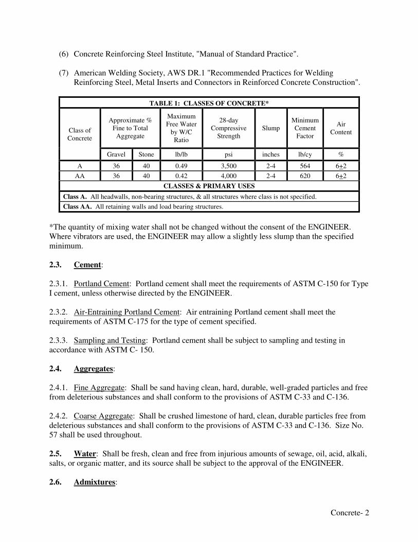
TABLE 1: CLASSES OF CONCRETE*
Class of Concrete
Approximate % Fine to Total
Aggregate
Maximum Free Water
by W/C Ratio
28-day Compressive
Strength Slump
Minimum Cement Factor
Air Content
Gravel Stone lb/lb psi inches lb/cy %
A 36 40 0.49 3,500 2-4 564 6+2
AA 36 40 0.42 4,000 2-4 620 6+2
CLASSES & PRIMARY USES
Class A. All headwalls, non-bearing structures, & all structures where class is not specified.
Class AA. All retaining walls and load bearing structures.
*The quantity of mixing water shall not be changed without the consent of the ENGINEER. Where vibrators are used, the ENGINEER may allow a slightly less slump than the specified minimum. 2.3. Cement: 2.3.1. Portland Cement: Portland cement shall meet the requirements of ASTM C-150 for Type I cement, unless otherwise directed by the ENGINEER. 2.3.2. Air-Entraining Portland Cement: Air entraining Portland cement shall meet the requirements of ASTM C-175 for the type of cement specified. 2.3.3. Sampling and Testing: Portland cement shall be subject to sampling and testing in accordance with ASTM C- 150. 2.4. Aggregates: 2.4.1. Fine Aggregate: Shall be sand having clean, hard, durable, well-graded particles and free from deleterious substances and shall conform to the provisions of ASTM C-33 and C-136. 2.4.2. Coarse Aggregate: Shall be crushed limestone of hard, clean, durable particles free from deleterious substances and shall conform to the provisions of ASTM C-33 and C-136. Size No. 57 shall be used throughout. 2.5. Water: Shall be fresh, clean and free from injurious amounts of sewage, oil, acid, alkali, salts, or organic matter, and its source shall be subject to the approval of the ENGINEER. 2.6. Admixtures:
Concrete- 3
2.6.1. Air-Entrainment: Shall fully meet the requirements of ASTM Designation C-260 and shall be subject to tests in accordance with ASTM C- 233. 2.6.2. Retarding Agents: Shall be included in the concrete mix only when specified on the Drawings or authorized by the ENGINEER. 2.6.3. Other Compounds: The use of calcium chloride or other accelerators or anti-freeze compounds will not be allowed. 2.7. Steel Reinforcement: 2.7.1. Reinforcing Bars: Shall conform to the “Steel” technical specification. 2.7.2. Accessories: All chairs and bolsters for use in exposed concrete shall have plastic covered tips or galvanized steel legs. 2.7.3. Shop Fabrication: Reinforcing steel shall be fabricated to shapes and dimensions indicated on the Drawings and in compliance with applicable provisions of ACI 315 and ACI 310. Bars shall be bent cold. Bars shall be prefabricated to detail and delivered to the job plainly tagged and ready to set. 2.8. Fiber: Shall be added at the rate of 3 pounds per cubic yard to all concrete unless otherwise specified the Drawing or Special Conditions. The fiber can be added at any time following the initial mixing of aggregate, cement and water. An extra 3-4 minutes shall be added to ensure that the fiber has been thoroughly distributed. The fiber is not a substitute for steel reinforcement where structures are concerned. 3. AIR-ENTRAINED CONCRETE
3.1. General: Unless otherwise noted, all concrete shall be air-entrained. Accomplish air-entrainment by using an air-entrained Portland cement or by using an air-entraining admixture with normal Portland cement. If the entrained air content falls below the specified limit when using air-entrained cement, an air-entraining admixture shall be used in sufficient quantity to bring the entrained air content within the specified limits. If the entrained air content is found to be greater than the maximum specified when using an air-entrained cement, the use of air-entraining cement shall be prohibited; and air-entrainment shall be accomplished by using an air-entraining admixture with normal Portland cement. Air-entraining admixtures shall be added in solutions to a portion of the mixing water by means of a mechanical batcher in a manner that will ensure uniform distribution of the agent throughout the batch. Air entraining agents shall comply with ASTM C-260. The air content of freshly mixed air-entrained concrete shall not be less than 4% or more than 6% of the volume of the concrete when determined by the methods specified in ASTM C-138,
Concrete- 4
C-173, or C-231. The air content shall be checked during the period of time that the required test cylinders are being cast. 3.2. Adjustment of Mix Proportions: When air-entrained concrete is specified, the amount of water and fine aggregate prescribed for normal concrete shall be reduced to compensate for the increased volume of air contained in the air-entrained concrete. 4. PROPORTIONING AND DESIGN OF MIXES
The CONTRACTOR shall be responsible for design mixes for each type of concrete shown and/or specified. Use an independent testing facility accepted by the ENGINEER for preparing and reporting proposed mix designs. Proportion design mixes by weight for each class of concrete required, complying with ACI 613 "Recommended Practice for Selecting Proportions for Concrete” and the following data reported:
a) Complete identification of aggregate source of supply.
b) Tests of aggregates for compliance with specified requirements.
c) Scale weight of each aggregate.
d) Absorbed water in each aggregate.
e) Brand, type, and composition of cement.
f) Brand, type, and amount of each component.
g) Amounts of water used in trial mixes.
h) Proportions of each material per cubic yard.
i) Gross weight and yield per cubic yard of trial mixtures.
j) Measured slump.
k) Measured air content.
l) Compressive strength developed at 7 days and 28 days, from not less than 3 test cylinders cast for each 7 day and 28 day test, and for each design mix.
Submit written reports of each design mix for each type and class of concrete to the ENGINEER, at least 7 calendar days prior to the start of the specified work. Include in each report the project identification name and number, date of report, name of contractor, name of concrete testing service, concrete class, source of concrete aggregates, manufacturer and brand name of manufactured materials, the precise proportions of the concrete mix, the properties specified
Concrete- 5
herein for the type and class of concrete, and the test results for each property specified for the design mix. The concrete mixes shall be designed so that the compressive strength of laboratory-cured cylinders, for each required strength, will be at least 15% greater than the minimum specified compressive strength; and so that not more than one test, of any 10 consecutive tests for strength, will have a value less than 90% of the required strength. The criteria specified herein are maximums or minimums, and shall not be construed to predetermine fixed quantities of materials in the mix design, or to preclude change of an accepted mix design at any time. Mix design adjustments may be requested by the CONTRACTOR when characteristics of materials, job conditions, weather, test results, or the circumstances warrant; at no additional cost to the COMMONWEALTH and as accepted by the ENGINEER. Laboratory test data for revised mix designs and strength results must be submitted to and accepted by the ENGINEER before being used in the work. 5. CONCRETE SAMPLING AND TESTING Standard tests of the materials and concrete may be made by the ENGINEER at any time he elects to do so. The testing service shall be selected by the COMMONWEALTH and paid by the COMMONWEALTH. Materials and installed work may require testing and retesting as directed by the ENGINEER at any time during the progress of the work. The ENGINEER shall be allowed free access to material stockpiles and facilities at all times. Tests, not specifically indicated to be done at the COMMONWEALTH'S expense, including the retesting of rejected materials and installed work, shall be done at the CONTRACTOR'S expense. Concrete shall be sampled and tested for quality control during the placement of concrete as follows:
a) Sampling Fresh Concrete: ASTM C-172, except modified for slump to comply with ASTM C-94.
b) Slump: ASTM C-143; one test for each set of compressive strength test specimens.
c) Air Content: ASTM C-231, pressure method; one for each set of compressive strength
test specimens.
d) Compression Test Specimens: ASTM C-31; one set of four standard cylinders for each compressive strength test.
e) Concrete Temperature: Test hourly when air temperature is 40oF and below, or when
80oF and above; and each time a set of compression test specimens are made.
Concrete- 6
f) Compressive Strength Tests: ASTM C-39; one set for each 50 cubic yards or fraction thereof, of each concrete class placed in any one day or in each separate feature of the project. One specimen will be tested at 7 days, one specimen will be tested at 28 days, and two specimens will be retained in reserve for later testing if required.
Test of a portion of a batch may be made on samples representative of that portion for any of the following purposes:
a) Determining uniformity of the batch.
b) Checking compliance with requirements for slump and air content when the batch is discharged over an extended period of time.
c) Checking compliance of the concrete with the specifications when the whole amount is
placed in a small structure, or a distinct portion of a large structure, is less than a full batch.
Test results shall be reported in writing to the ENGINEER and CONTRACTOR on the same day that tests are made. Reports of compressive strength tests shall contain the project identification name and number, date of concrete placement, name of contractor, name of concrete supplier and truck number, name of concrete testing service, concrete type and class, location of concrete batch in the structure, design compressive strength at 28 days; compressive breaking strength for both 7 day tests and 28 day tests. The testing service shall take core samples of in-place concrete when test results are such that there is reasonable doubt that the specified concrete strengths and other characteristics have not been attained in the structure. The testing service shall conduct tests to determine the strength and other characteristics of the in-place concrete by compression tests on cored cylinders complying with ASTM C-42, or by load as outlined in ACI 318, or by other methods as directed. The CONTRACTOR shall provide stable, insulated storage boxes, equipped with thermostatically controlled heat or an approved alternate facility for the storage of compression test cylinders in the first 24 hours after molding. 6. FAILURE TO MEET STRENGTH REQUIREMENTS
Concrete should break at 75% of targeted strength at 7 days. If it does not, do not begin
backfill operation until the 28 day test has been done. The 28 day test should be at or
greater than the target strength.
In the event that concrete tested in accordance with the requirements herein fails to meet the specified strength requirements, the CONTRACTOR may be required to remove such concrete from the structure and replace such sections in a manner satisfactory to the ENGINEER. The cost of the removal and replacing such sections of concrete shall be borne by the CONTRACTOR.
Concrete- 7
When it is determined that such concrete shall be removed and replaced, the CONTRACTOR shall be notified in writing, stating the extent of the replacement to be made. Neither additional compensation nor time extensions will be granted for such work. 7. BATCHING AND MIXING
7.1. Equipment: Ready-mix concrete may be used. Measurements of materials for ready-mixed concrete shall conform to ASTM C 94. The ENGINEER shall have free access to the mixing plant at all times. Truck mixers will be allowed provided the use of this method will cause no violation of any applicable provisions of specifications for concrete contained herein. Truck mixers, unless otherwise authorized by the ENGINEER, shall be of the revolving drum-type, watertight, and so constructed that the concrete can be mixed to ensure the uniform distribution of materials throughout the mass. Each truck mixer shall be equipped with a tank of known capacity, which shall be equipped with an accurate device for measuring the amount of water added. Truck mixers and agitators shall be operated within the limits of capacity and speed of rotation designated by the manufacturer of the equipment. 7.2. Mixing Time: Neither the speed nor the volume capacity of the mixer shall exceed those recommended by the manufacturer. Excessive over mixing, requiring additions of water to preserve the required consistency will not be permitted. The mixing time for each batch, after all solid materials are in the mixer drum, provided that all the mixing water shall be introduced before 1/4 of the mixing time has elapsed, shall be not less than 1-1/2 minutes for mixers having capacities up to 2 cubic yards. For mixers of larger capacities, this minimum shall be increased 15 seconds for each cubic yard or fraction thereof of additional capacity. When a truck mixer is used, each batch of concrete shall be mixed not less than 50 nor more than 100 revolutions, at a mixing speed of not less than 4 rpm after all materials are in the mixer drum. After adding all water, cement and aggregates to the mixer deliver and place concrete in its final position within the time limits of the following table. Do not use concrete that has developed initial set, that has become segregated or that has not been delivered within the time limits listed.
TIME OF DISCHARGE LIMITS (minutes)
Normal Concrete Retarded Concrete
Agitated Agitator Non-Agitated Agitated Agitator Non Agitated
60 45 30 90 60 30
1. All times begin when cement enters the mixer.
2. Normal concrete is concrete without additional water-reducing admixture.
3. Retarded Concrete is concrete to which an admixture has been added.
4. Agitated Concrete is concrete that has been continuously agitated until placed.
5. An Agitator is a truck with paddles.
7.3. Conveying: Concrete shall be conveyed from mixer to forms as rapidly as practicable, by methods which will prevent segregation, loss of ingredients, or displacement of
Concrete- 8
reinforcement. There shall be no vertical drop greater than 5 feet, except where suitable equipment is provided, to prevent segregation and where specifically authorized by the ENGINEER. The use of long chutes, troughs, belts, and pipes for conveying concrete from the mixing plant or point of delivery to the forms will be allowed only upon written permission. When such conveyors are allowed and the quality of concrete or methods of placing or working it therein are not satisfactory, the CONTRACTOR shall discontinue their use and re-equip his plant so that concrete will be placed in a satisfactory manner. Troughs, pipes, or chutes used as aids in placing concrete shall be arranged and used in such a manner that ingredients of the concrete are not separated. Where steep slopes are required, the chutes shall be equipped with baffle boards or be in short lengths that change the direction of movement. All chutes, troughs, and pipes shall be maintained clean and free from coating of hardened concrete by thoroughly flushing with water after each run or when out of operation for more than 30 minutes. Water used for flushing shall be discharged clear of concrete in place. The troughs, pipes, and chutes shall be either of metal or metal lined and shall extend as near as possible to the point of deposit. Aluminum or aluminum alloy troughs, pipes, or chutes will not be permitted. Where wall forms exceed 5 feet in height, suitable measures, such as the use of tremie tubes, where practicable, or portholes, shall be provided in the forms to limit the vertical drop of the concrete to a maximum of 5feet. Openings shall be spaced around the perimeter of the formed area so that lateral flow of fresh concrete will be limited to 3 feet. Drop chutes, which may be provided to convey the concrete through wall ports, shall have an outside pocket under each form opening to stop the concrete and allow it to flow easily over into the form without separation. No concrete shall be placed until the ENGINEER has given his approval of the subgrade, forms, and reinforcing steel in place. If the reinforcing steel is not placed in accordance with the Drawings, the ENGINEER shall stop the CONTRACTOR from placing any concrete until the error is corrected. Under no circumstances shall an attempt be made to correct errors by inserting additional unscheduled bars. No concrete shall be placed except in the presence of the ENGINEER’s representative, and the CONTRACTOR shall give reasonable notice of his intention to place. Before any concrete is placed, the forms and subgrade shall be free of chips, dirt, sawdust, or other extraneous materials. 8. PLACEMENT OF STEEL
8.1. Storage: Reinforcing steel delivered to the job, and not immediately placed in forms shall be protected from mud and excessive rust producing conditions. 8.2. Placement: Metal reinforcement shall be accurately placed in accordance with the plans and shall be adequately secured in position with not less than 16-gage annealed wire or suitable clips at intersections. Reinforcement shall be held securely the required distance from the forms by concrete or metal chairs and spacers, except that broken brick or tile may be used to support
Concrete- 9
reinforcement in footings on ground. Nails shall not be driven into outside forms to support reinforcement. Space metal chairs, spacers, and hangers shall be in accordance with ACI 315 and ACI 318. Metal reinforcement, at the time concrete is placed, shall be free from rust scale or other coatings that will destroy or reduce bond. Bars with kinks or bends not shown on the plans shall not be used. A thin coating of firmly attached rust shall not be cause for rejection. 8.3. Splicing: Splicing of reinforcement not shown on Drawings will conform to the splicing table in the “Steel” section of these Technical Specifications. Splices shall not be made at point of maximum stress and shall provide sufficient lap to transfer stress by bond. When splicing is
approved by the ENGINEER the splicing shall be done with mechanical couplers or as
approved by the ENGINEER. Do not use mechanical couplers for splices at angles and corners. If the bars have to be overlapped to use a particular splicing method, the bars shall be overlapped
8.4. Inspection: The ENGINEER or his representative shall have 24 hour notice and the opportunity to inspect and pass upon the placement of reinforcing steel before concrete is placed, as follows: (1) For non-typical conditions. . Each condition (2) For typical conditions . . . . . . Each major placement Such inspection shall be in the nature of assisting the CONTRACTOR to minimize errors, and in no case will they relieve the CONTRACTOR of his responsibility to provide the materials and workmanship required by the Contract Documents. 9. PLACEMENT OF CONCRETE
9.1. General: Concrete shall be placed in accordance with the “Times of Discharge” listed in these Technical Specifications. In hot weather or under conditions contributing to quick stiffening of the concrete, or where the temperature of the concrete is 85oF or above, the times shall be reduced to one-half the time as specified. The ENGINEER may allow a longer time, providing the setting time of the concrete is increased a corresponding amount by the addition of an approved set-retarding mixture. Concrete shall be deposited as closely as possible to its final position in the forms so that flow within the mass and consequent segregation is reduced to a minimum. Vibrators may be used to aid in the placement of the concrete provided they are used under experienced supervision, and the forms designed to withstand their action. The duration of vibration shall be limited to that necessary to produce satisfactory consolidation without causing objectionable segregation. Vibration shall not be applied directly to the reinforcement steel or the forms or to concrete which has hardened to the degree that is does not become plastic when vibrated. When a vibrator is used space the concrete along form surfaces a sufficient amount to prevent excessive size or numbers of air-void pockets in the concrete surface.
Concrete- 10
9.2. Addition of Water at Jobsite: When concrete arrives at the jobsite with a slump that is lower than allowed by design or specification and/or is of such consistency so as to adversely affect the placeability of the concrete, water can be added to the concrete to bring the slump up to acceptable or specified level. This can be done at the job site as long as the specified slump and/or water-cement ration is not exceeded. Addition of water in excess of the design mixing water will affect concrete properties, such as reducing strength and making it more susceptibility to cracking. Before any water is added to the mixture a slump test must be performed. If it is decided to add water with the approval of the ENGINEER, the amount of water must be measured and recorded. The water amount shall not be more than 1 gallon of water at any one time. Once water is added the concrete shall be mixed by having the mixer drum complete at least 30 revolutions at mixing speed. Once water is added another slump test should be performed.
Water should not be added if the maximum water-cement ration is reached, the maximum slump is obtained or more than 1/4 cubic yard of concrete has been discharged from the mixer. 9.3. Lifts in Concrete: The permissible depth of concrete placed in each lift shall be as shown on the Drawings or specified herein. All concrete shall be deposited in horizontal layers not exceeding 20 inches in thickness, unless otherwise authorized or directed. The placement shall be carried on at such a rate that the formation of cold joints will be prevented. If a delay occurs in excess of a 40 minute interval between any two consecutive batches or loads, or in case of any delay between placing batches that allows previously placed concrete to take initial set, the CONTRACTOR shall discontinue the placing of concrete and make, at his own expense, a construction joint satisfactory to the ENGINEER before proceeding with the placing operations. Remove any portion of the previously placed concrete that is deemed necessary for the proper formation of the construction joint and no payment shall be made to the CONTRACTOR for the concrete removed. The 40 minute limitation cited immediately above may be extended in those cases where an approved type retarder is added to the concrete mixture, to delay the set of the concrete. Use of a retarder in the mix shall be subject to approval of the ENGINEER. Hoppers, chutes, and pipes shall be used as necessary to prevent splashing of mortar on forms and reinforcing above the layer being placed. 9.4. Placing Temperature: Concrete shall be mixed and placed only when the atmospheric temperature is at least 40oF and steady or rising, unless special permission to place is obtained from the ENGINEER. When the atmospheric temperature may be expected to drop below 40oF at the time concrete is delivered to the work site, during placement or any time during the curing period, the following provisions shall apply:
a) The temperature of the concrete at the time of placing shall not be less than 50oF or more than 90oF. The temperature of neither aggregates nor mixing water shall be more than
Concrete- 11
100oF just prior to mixing with the cement. The ENGINEER shall approve all methods for heating the materials and protecting the concrete.
b) When the daily minimum temperature is less than 40oF, concrete structures shall be insulated or housed and heated after placement. The temperatures of the concrete and air adjacent to the concrete shall be maintained at not less than 50oF or more than 90oF for the duration of the curing period.
c) Methods of insulation, housing and heating the structure shall conform to "Recommended Practices for Cold Weather Concreting", ACI Standard 306.
d) When dry heat is used to protect concrete, means of maintaining an ambient humidity of at least 40% shall be provided unless the concrete has been coated with curing compound as specified herein or is covered tightly with an approved impervious material.
e) Salt, chemicals, or other materials shall not be mixed with the concrete for the purpose of preventing freezing.
f) Before any concrete is placed, all ice, snow, and frost shall be completely removed and the temperature of all surfaces to be in contact with the new concrete shall be raised to as close as may be practical to the temperature of the new concrete that is to be placed thereon. No concrete shall be placed on a frozen sub grade or on one that contains frozen materials.
When climatic or other conditions are such that the temperature of the concrete may reasonably be expected to exceed 85oF at the time of delivery at the work site, during placement, or during the first 24 hours after placement, the following provisions shall apply:
a) The CONTRACTOR shall maintain the temperature of the concrete below 85oF during mixing, conveying, and placing. Methods used shall conform to "Recommended Practice for Hot Weather Concreting", ACI Standard 305.
b) The concrete shall be placed in the work immediately after mixing. Truck mixing shall
be delayed until only time enough remains to accomplish it before the concrete is placed.
c) Exposed concrete surfaces which tend to dry or set too rapidly shall be continuously moistened by means of fog sprays or otherwise protected from drying during the time between placement and finishing, and after finishing.
d) Finishing of slabs and other exposed surfaces shall be started as soon as the condition of
the concrete allows and shall be completed without delay.
e) Concrete surfaces exposed to the air shall be covered as soon as the concrete has hardened sufficiently and shall be kept continuously wet for at least the first twenty-four (24) hours of the curing period, and for the entire curing period unless curing compound is applied as specified in accordance with these Technical Specifications.
Concrete- 12
f) Formed surfaces shall be kept completely and continuously wet for the duration of curing
period (prior to, during, and after form removal) or until curing compound is applied as specified in accordance with these Technical specifications.
g) If moist curing is discontinued before the end of the curing period, white-pigmented
curing compound shall be applied immediately.
h) Cover reinforcing steel with water soaked burlap if it becomes too hot, so that the steel temperature will not exceed the ambient air temperature immediately before embedment in concrete.
i) Wet forms thoroughly before placing concrete.
Concrete placement shall not be permitted when, in the opinion of the ENGINEER, the sun, heat, wind, or humidity prevents proper placement and consolidation. 9.5. Concrete on Rock Foundations: Rock surfaces upon which concrete is to be placed shall be clean, free from oil, standing or running water, mud, objectionable coatings, debris, loose, semidetached, or unsound fragments. Faults or seams shall be cleaned to a depth satisfactory to the ENGINEER, and to firm rock on the sides. Immediately before concrete is placed, all such rock surfaces shall be cleaned thoroughly by use of high velocity air-water jets, wet sandblasting, or other means satisfactory to the ENGINEER. All rock surfaces shall be kept continuously wet for 48 hours and all approximately horizontal surfaces shall be covered, immediately before the concrete is placed, with a layer of mortar of the same sand-cement ratio as used in the concrete; unless this criterion is waived by the ENGINEER. 9.6. Concrete on Earth Foundations: Unless otherwise authorized, all concrete shall be placed upon clean, damp surfaces free from frost, ice, or deleterious materials, and standing or running water. Concrete shall not be placed in mud, dried porous earth or upon fill that has not been subject to approved rolling or tamping until optimum compaction has been obtained. The CONTRACTOR shall take all measures to accomplish the results specified in this paragraph. 9.7. Vertical Joint Spacing: The layout of all monoliths shall be shown on the Drawings or as directed and approved by the ENGINEER before construction is started. 9.8. Placing Concrete through Reinforcement: In dropping concrete through reinforcement, care shall be taken that no segregation of the coarse aggregate occurs. 9.9. Concrete Pumps: concrete pumps may be used, with the approval of the ENGINEER, provided the designated strength and slump are obtained. Before any concrete is ordered the proposed concrete mixture shall be submitted to the Project ENGINEER for review and approval. 9.10. Placing Concrete Underwater: Do not expose concrete to the action of water before setting, or deposit it in water, except upon the ENGINEER’S written permission. Mix all
Concrete- 13
concrete deposited under water in proportions specified for Class A. Place concrete deposited under water in its final position by means of a tremie or by other approved methods. Do not disturb it after depositing. Provide a sufficient number of tremies or other approved devices to ensure proper distribution of concrete to all portions of the seal. Maintain calm water at the point of deposit. Do not place any concrete in flowing water. Ensure that all form work, such as interlocking sheeting, designed to retain concrete under water is water-tight. Regulate the consistency of the concrete to prevent segregation of materials. Maintain the surface of the concrete as nearly horizontal as practical at all times. To ensure thorough bonding, place each succeeding layer before the preceding layer has taken its initial set. Close the discharge end at the start of work to prevent water from entering the tube. Induce the flow of concrete by slightly raising the tremie, but always keeping the discharge end in the deposited concrete. Stop the flow by lowering the tremie. Provide a continuous flow and, unless unavoidable, do not interrupt it until completing the work. The Division will allow dewatering when the concrete is sufficiently strong to withstand hydrostatic pressure, but in no case in less than 3 calendar days after placing, or such additional length of time as the ENGINEER may direct. Remove all laitance or other unsatisfactory material from the exposed surfaces by scraping, chipping, or other means which will not injure the concrete surface, as the Engineer directs. When it is necessary to use a concrete seal in construction of a foundation, construct it as hereinafter described. A concrete seal in a foundation is that volume of concrete placed under water by means of a tremie or other approved means for sealing the entire bottom area of the excavated pit within the cofferdam against hydrostatic pressure, to dewater the excavation and construct the remainder of the foundation in dewatered forms. Use Class A concrete for the seal, and in general make the thickness of the seal course 0.43 times the hydrostatic head exerting pressure on the bottom of the foundation, or of a thickness as specified in the Drawings. Place the corners of the seal to an elevation lower than the remaining surface of the seal course for the purpose of dewatering. In such cases, do not exceed an elevation difference between the corners and the remaining surface of 6 inches. 10. JOINTS
10.1. Construction Joints: Construction joints shall be located as indicated on the Drawings, Special Conditions/Notes, AML Standard Details, or as approved by the ENGINEER. Where
no joint spacing is indicated, joints shall be placed at a minimum of 10 feet and a maximum
of 20 feet. The surfaces of construction joints shall be clean when covered with fresh concrete. Cleaning shall consist of the removal of all lattice, loose or defective concrete, and foreign material. Cleaning of the surface of construction joints shall be accomplished by the use of high velocity air-water jets, wet sandblasting, or other effective means satisfactory to the ENGINEER. Surfaces of construction joints that have been permitted to dry by reason of the succeeding lift or adjoining concrete not being placed within the specified post-curing period shall be moistened and kept continuously moist for at least 48 hours immediately prior to the placing of the
Concrete- 14
succeeding lift of adjoining concrete. All pools of water shall be removed from the surface of construction joints before the new concrete is placed. 10.2. Expansion Joints: Expansion joints shall be located as indicated on the Drawings, Special Conditions, AML Standard Details, and as approved by the ENGINEER. Where no joint spacing is indicated joints shall be placed at 90-100 foot centers. The joints will be sealed with an approved material as listed in the AML Standard Detail or detailed in the Drawings and/or Special Conditions and project notes. 11. PATCHING CONCRETE
Any concrete which is not formed as shown on the Drawings, or for any reason is out of alignment or level, or shows a defective surface, or shows defects which reduce the structural adequacy of a member or members, shall be considered as not conforming to the intent of these Technical Specifications and shall be removed from the job by the CONTRACTOR at his expense, unless the ENGINEER grants permission to patch the defective area. Permission to patch any such surface shall not be considered a waiver of the ENGINEER'S right to require complete removal of the defective work if the patching does not, in his opinion, satisfactorily restore the quality and appearance of the surface, or if patching does not restore the structural adequacy of the member or members. Repair work shall be performed only when the ENGINEER is present. Repair of formed surfaces shall be started within 24 hours after removal of the forms. All new concrete shall be secured with keys, dovetails, or anchors. After removing forms, inspect all concrete surfaces. Patch any pour joints, voids, honeycomb, stone pockets, or other defective areas permitted by the ENGINEER to be patched, and all tie holes (except where noted otherwise elsewhere). Where necessary, chop away defective areas to a depth of not less than one inch with the edges perpendicular to the surface. Apply bonding agent to area to be patched with care to keep bonding agent off of areas to remain exposed. Apply bonding agent in accordance with manufacturer's printed instructions. The patching mortar shall be made of the same material (and of approximately the same proportions) as used in the concrete for the same location except that the coarse aggregate shall be omitted for concealed locations. Patching mortar shall be of same composition as adjacent concrete in exposed-aggregate concrete. The mortar shall not be richer than one part cement and three parts sand. White Portland cement shall be substituted for a part of the gray Portland cement so as to match the color of the surrounding concrete. The proportion of white and gray cements shall be determined by making a trial patch. The amount of mixing water shall be as little as is consistent with the requirements of handling and placing. The mortar shall be retempered without the addition of water by allowing it to stand for a period of one hour, during which time it shall be mixed occasionally with a trowel to prevent setting. Compact the mortar thoroughly into place, and screed off so as to leave the patch slightly higher than the surrounding surface. Leave patch undisturbed for a period of 1-2 hours to permit initial shrinkage before beginning final finishing. Finish patch in such a manner as to match the adjoining surface. All patches shall be finished and cured in accordance with requirements for
Concrete- 15
the surface in which patch occurs. Keep patch moist for not less than three days after installation. For unexposed concrete the following applies:
a) Tie-holes left by withdrawal of rods, or the holes left by removal of ends of ties shall be filled solidly with mortar after first being wet thoroughly.
b) For holes passing entirely through a wall, a plunger-type grout gun shall be used to force the mortar through the wall, starting at the back face. A piece of burlap or canvas shall be held over the hole on the outside; and when the hole is completely filled, the excess mortar shall be struck off with the cloth flush with the surface.
c) Holes not passing entirely through the walls shall be filled with a small tool that will permit packing the hole solidly with mortar. Any excess mortar at the surface of the wall shall be struck off flush with a cloth.
12. FINISHING
12.1. General: In order that the rubbing required herein shall be effective, non-supporting forms may be removed after 24 hours, provided the concrete is sufficiently strong not to be injured thereby. Initial rubbing required shall be completed within 48 hours after concrete placing. If possible, patching and rubbing shall be done at the same time. This requirement regarding form removal is secondary to heating requirements, and the specifications heretofore included regarding heating of concrete shall take precedence. Joints and edges of unformed surfaces that will be exposed to view shall be chamfered or
finished with molding tools. At tops of walls, strike-off smooth horizontal offsets and similar unformed surfaces occurring adjacent to formed surfaces and finish with a texture matching adjacent formed surfaces. Continue final surface treatment of formed surfaces uniformly across adjacent unformed surfaces, unless otherwise shown. 12.2. Type I Finish: Type I finish is a standard rough form finish for formed concrete surfaces not exposed-to-view in the finish work or by other construction, unless otherwise shown or specified. Driveways and sidewalks receive a broom/brush finish. This is a concrete surface texture imparted by the form facing material used, with defective areas repaired and patched as specified, and fins and other projections exceeding 1/4 inch height rubbed down with wood blocks. Non-exposed wall backs & Driveways shall have a Type I Finish.
12.3. Type II Finish: Type II finish is a standard smooth finish for formed concrete surfaces exposed-to-view or that are to be covered with a coating of material applied directly to the concrete. This is the as-cast concrete surface as obtained with the form facing material, with defective areas repaired and patched as specified, and fins and other projections on the surface completely removed and smoothed. All surfaces that will show in the finished work shall be rubbed down with a coarse carborundum stone and covered with a masonry coating material. Exposed wall faces, Cast-in-place headwalls, and drop boxes shall have a Type II Finish.
Concrete- 16
12.4. Type III Finish: Type III finish is a float finish to be used on all horizontal surfaces not subject to wear. The finish shall be accomplished by placing an excess of materials in the form and removing or striking of such excess with a wooden template, forcing coarse aggregate below the surface. After the concrete has been struck off as described, the surface shall be thoroughly worked and floated by hand with a wooden float leaving a fine grained, smooth-sanded surface. Concrete retaining wall horizontal surfaces and concrete panels shall have a Type III
Finish.
13. CURING AND PROTECTION
13.1. General: Protect freshly placed concrete from premature drying and from excessive cold or hot temperatures, and maintain, without drying, at a relatively constant temperature for a period of time necessary for hydration of cement and proper hardening. Start initial curing as soon as free water has disappeared from concrete surface after placing and finishing. If Weather permits, keep continuously moist for not less than 72 hours. Unhardened concrete shall be protected from heavy rains and flowing water. All concrete shall be adequately protected from damage. Begin final curing procedures immediately following initial curing and before concrete has dried. Continue final curing for at least 168 cumulative hours (not necessarily consecutive) during which concrete has been exposed to air temperatures above 50oF. Avoid rapid drying at end of final curing period. All hot weather concreting shall conform to requirements set forth in ACI 305, "Recommended Practice for Hot Weather Concreting". 13.2. Moist Curing: Concrete shall be moist cured by maintaining all surfaces continuously (not periodically) wet for the duration of the entire curing period. Water for curing shall be clean and free from any elements which will cause staining or discoloration of the concrete. Where wooden forms are used and left in place during curing, the wood shall be kept wet at all times. 13.3. Membrane Curing: At the option of the CONTRACTOR and when approved by the ENGINEER, the concrete may be cured with an approved curing compound of the surface membrane type in lieu of moist curing with water. The curing compound shall be applied to formed surfaces immediately after the forms have been removed and the surfaces cleaned of any loose sand, mortar, and debris. The surface to receive the compound shall be moistened thoroughly with water and the compound applied as soon as the moisture film has disappeared, but when the surface is still damp. On unformed surfaces the compound shall be applied immediately after the surface loses its free water and has a dull appearance. Apply the curing compound in a two-coat continuous operation by approved spraying equipment and at coverage of not more than 200 square feet per gallon for both coats. Apply the second coat to overlap the first coat in a direction at approximately right angles to the direction of the first application. Concrete surfaces, which are subjected to heavy rainfall within 3 hours after the curing compound has been applied, shall be re-sprayed by the method and at the rate of coverage specified herein. Adequately protect all concrete surfaces on which curing compound have been applied for the duration of the entire curing period from any damage that would
Concrete- 17
disrupt the continuity of the curing membrane. The curing compound shall conform to Type 2 or Type 3 of ASTM Designation C 309. All curing compound shall be delivered to the site of the work in the original sealed container bearing the name of the manufacturer, the brand name and the manufacturer's batch number. The compound shall be approved prior to use. Store the compound to prevent damage to the containers, and protect water-emulsion types from freezing. 13.4. Moisture Cover Curing: Cover concrete surfaces with moisture-retaining cover for curing concrete, placed in widest practicable width with sides and ends lapped at least 3 inches and sealed by waterproof tape or adhesive. Immediately repair any holes or tears during curing period using cover material and waterproof tape. 13.5. Curing Formed Surfaces: Cure formed concrete surfaces and other similar surfaces by moist curing with forms in place for full curing period or until forms are removed. If forms are removed, continue curing by other applicable methods specified herein. 13.6. Curing Unformed Surfaces: Initially cure unformed surfaces, such as slabs and other flat surfaces, by moist curing; and final cure by applicable methods specified herein. 13.7. Cold Weather: The air and forms in contact with the concrete shall be maintained at temperatures above 40oF for at least 5 days, and at a temperature above freezing for the remainder of the specified curing period. Concrete, permitted to be cured with curing compounds, shall be provided the same protection against freezing and low temperatures. No fire or excessive heat shall be permitted near or in direct contact with concrete at any time. All cold weather concreting shall conform to requirements set forth in ACI 306, "Recommended Practice for Cold Weather Concreting". 14. FORMWORK
14.1. General: Unless otherwise shown or specified, design, construct, erect, maintain and remove forms, and related structures for cast in place concrete work in compliance with the American Concrete Institute Standard ACI 347, "Recommended Practice for Concrete Formwork". 14.2. Forms for Exposed Finish Concrete: Unless otherwise shown or specified, construct all formwork for exposed concrete surfaces with plywood, metal, metal-framed plywood-faced or other acceptable panel-type materials, to provide continuous, straight, smooth exposed surfaces. Furnish in largest practicable sizes to minimize number of joints and to conform to joint system shown on drawings. Provide form material with sufficient thickness to withstand pressure of newly placed concrete without bow or deflection. Use plywood complying with the U.S. Product Standard PS-1 "B-B (Concrete Form) Plywood" Class I, Exterior Grade or better, mill-oiled and edge-sealed, with each piece bearing legible trademark of an approved inspection agency, unless otherwise acceptable to ENGINEER.
Concrete- 18
14.3. Forms for Unexposed Finish Concrete: Form concrete surfaces, which will be unexposed in finished structure with plywood, lumber, metal, or other acceptable material. Provide lumber dressed on at least two edges and one side for tight fit. Use 6 inch or 8 inch wide lumber, nominal 1 inch thickness, or as specified for exposed concrete, at CONTRACTOR'S option. 14.4. Earth Forms for Trench Excavation: Where trench excavation is used and walls of excavation are neatly cut in good soil, side forms may be omitted for footings and for some select retaining walls as permitted by the ENGINEER. 14.5. Formwork Accessories: Form ties where concrete is unexposed shall be standard crimped snapties. Form ties where concrete is exposed, as finish shall be a snap-in form tie with plastic cones. Form ties shall be manufactured by Meadow Steel Products Company, Dayton Sure-Grip and Shore Company, Universal Form Clamp Company, or equivalent. Form releasing agent shall be non-staining "Form Oil" as manufactured by Texaco, Sinclair, Georgia Carolina Company, or equivalent. 14.6. Form Construction: Forms shall be constructed in accordance with ACI 347 and shall conform to shape, lines, and dimensions of members indicated, and shall be substantial and sufficiently tight to prevent leakage of mortar. They shall not deflect under dead load weight of concrete as a liquid or of construction load. Forms shall be braced or tied together so as to maintain position and shape. Construct forms so that they can be removed readily without hammering or prying against concrete. Forms for exposed concrete shall be carefully made and accurately placed to obtain correct shape and lines. The CONTRACTOR shall be fully responsible for adequacy of formwork in its entirety. Forms shall support loads they will be required to sustain and shall maintain their dimensional and surface correctness to produce members required by the Drawing. Construct a trap door in the bottom of wall forms for access to interior of forms to permit inspection and cleaning. Build bulkheads with keys in walls, footings, and slabs where it is necessary to stop placing of concrete. 14.7. Reused Forms: Forms which are reused shall be thoroughly cleaned of dirt, debris, concrete, and foreign matter. Forms shall not be reused if they have developed defects which would affect their tightness and strength. Marred surfaces in contact with concrete shall be repaired before reuse. 14.8. Plywood Forms: Plywood forms shall be of material as specified in these Technical Specifications. Joints shall be butted tight on solid bearings. Arrangement of panels shall be orderly and symmetrical, and use of small pieces shall be avoided. Use chamfered forms for external corners of concrete which will be exposed in finished work. 14.9. Removal of Forms: Formwork not supporting weight of concrete, such as walls and similar parts of the work may be removed 24 hours, but no sooner, after placing concrete, provided concrete is sufficiently hard not to be damaged by form removal operations, and
Concrete- 19
provided curing and protection operations are maintained. The CONTRACTOR shall assume full responsibility for removal of formwork and forms. 14.10. Inspection and Approval of Formwork: Forms, form joints, and reinforcing steel placement shall be checked by the ENGINEER before closing the forms. Do not place concrete in any form until the placing of steel and erection of formwork have been completed and approved by the ENGINEER. Immediately after completion of pouring, adjust the tops of all forms to line and approved by the ENGINEER as to conformity within the tolerances specified herein. 15. EMBEDDED ITEMS
15.1. General: Before placing concrete determine that all embedded items are firmly and securely fastened in place as indicated on the Drawings or required by the ENGINEER. Thoroughly clean all embedded items ensuring they are free of oil and other foreign matter such as loose coatings of rust, paint, and scale. The embedding of wood or other perishable materials in concrete shall be prohibited unless specifically directed or authorized by the ENGINEER. Any air or water lines or the materials embedded in structures, as construction expedients authorized by the ENGINEER, shall conform to the above requirements and, upon completion of their use, shall be backfilled with concrete or grout as directed by the ENGINEER. 15.2. Pipe Embedded in Concrete: Where pipe is partially or wholly encased in concrete ensure the pipe is firmly and securely held in place so that the alignment and grade of the pipe is not disturbed while the concrete is placed around the pipe. The trench excavated for the pipe shall be thoroughly cleaned and free from any foreign matter and completely filled with concrete to a depth one foot over the pipe. 16. PRECAST AND/OR PRESTRESSED CONCRETE STRUCTURES
All concrete structures (i.e. headwalls, culverts, lagging, etc.) that are precast and/or pre-stressed before being delivered shall meet the requirements of this Technical Specification as well as the Technical Specification covered in the Kentucky Transportation Cabinet's "Standard Specifications for Road and Bridge Construction", current edition. All structures shall carry a certification from the manufacturer that they will meet these specifications. 17. BACKFILL
Backfill consisting of either earthen material or rock shall not be placed until after the 7
day compressive strength test has been completed and reviewed by the ENGINEER. The
ENGINEER shall approve when placement of the backfill can begin.
Ver. 7-2013 Concrete Block- Interlocking Mat- 1
CONCRETE BLOCK - INTERLOCKING MAT
1. SCOPE
The work shall consist of furnishing and installing interlocking cellular concrete blocks where shown on the Drawings or as otherwise directed by the ENGINEER. Block style must be pre-approved by the ENGINEER prior to being brought to the site. 2. MATERIALS
2.1. Concrete: Shall be Class A concrete conforming to the “Concrete” technical specification.
2.2. Cellular Concrete Blocks: The cellular concrete blocks shall be interlocking components dimensioned within a 16 inch module. Each component shall lock into the minimum of three adjacent components in a manner which inhibits horizontal movement. The blocks shall have a thickness of either 4 inches or 6 inches and shall be specified on the drawings. The unit weight of the concrete used shall not be less than 125 pounds per cubic foot on an oven dried basis. Pre-cast concrete and machine made blocks shall have a compressive strength of 4,000 psi minimum. Machine made concrete blocks strength shall be determined by testing random cubes, cut from the body of the block. The assembled cellular block system shall have voids at the ground/block interface of a minimum 16% and shall provide, when required, adequate channels between cells below the top level of the blocks for the migration of vegetation from cell to cell if called for on the Drawings. The voids may also be filled with stone as specified or as directed by the ENGINEER. The assembled cellular concrete block system shall flex to a minimum of 3 feet radius in any two directions a minimum of 60º apart without separation of the blocks at the base. The interlock must remain securely fastened at this radius. Blocks shall interlock on all sides. 2.3. Aggregate: Shall conform to the “Crushed Aggregate and Channel Lining” technical specification. 3. CONSTRUCTION
The slope must be stable independent of the erosion system. Filled slopes must be compacted to minimum 90% proctor. Before placing the cellular concrete block system on the underlying geotextile as specified on the Drawings, the slope shall be inspected to insure that it is free from obstructions, such as tree roots, projecting stones or foreign matter, voids or soft areas should be filled with the suitable material and well compacted. Although some variation in contour will be permitted, no sudden changes in level can be accepted. The maximum difference in level between any cuts shall be one and 1-1/2 inch.

Ver. 7-2013 Concrete Block- Interlocking Mat- 2
Pour a concrete header with the top edge flush with the top surface of the concrete blocks. The bottom shall extend below the concrete blocks as noted on the AML Standard Detail. After the subgrade is prepared construct a compacted base using dense grade aggregate compacted to minimum 90% proctor. The entire perimeter of the cellular block system shall be turned and buried beneath the adjacent ground level to a depth of not less than 3 feet or as shown on the drawings.
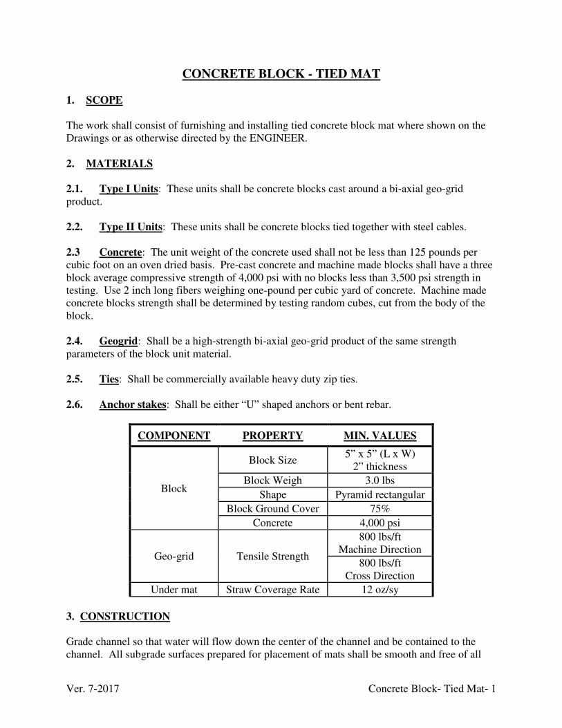
Ver. 7-2017 Concrete Block- Tied Mat- 1
CONCRETE BLOCK - TIED MAT
1. SCOPE
The work shall consist of furnishing and installing tied concrete block mat where shown on the Drawings or as otherwise directed by the ENGINEER. 2. MATERIALS
2.1. Type I Units: These units shall be concrete blocks cast around a bi-axial geo-grid product. 2.2. Type II Units: These units shall be concrete blocks tied together with steel cables. 2.3 Concrete: The unit weight of the concrete used shall not be less than 125 pounds per cubic foot on an oven dried basis. Pre-cast concrete and machine made blocks shall have a three block average compressive strength of 4,000 psi with no blocks less than 3,500 psi strength in testing. Use 2 inch long fibers weighing one-pound per cubic yard of concrete. Machine made concrete blocks strength shall be determined by testing random cubes, cut from the body of the block. 2.4. Geogrid: Shall be a high-strength bi-axial geo-grid product of the same strength parameters of the block unit material. 2.5. Ties: Shall be commercially available heavy duty zip ties. 2.6. Anchor stakes: Shall be either “U” shaped anchors or bent rebar.
COMPONENT PROPERTY MIN. VALUES
Block
Block Size 5” x 5” (L x W)
2” thickness
Block Weigh 3.0 lbs
Shape Pyramid rectangular
Block Ground Cover 75%
Concrete 4,000 psi
Geo-grid Tensile Strength
800 lbs/ft Machine Direction
800 lbs/ft Cross Direction
Under mat Straw Coverage Rate 12 oz/sy
3. CONSTRUCTION Grade channel so that water will flow down the center of the channel and be contained to the channel. All subgrade surfaces prepared for placement of mats shall be smooth and free of all

Ver. 7-2017 Concrete Block- Tied Mat- 2
rocks, sticks, roots, other protrusions, or debris of any kind. The prepared surface shall provide a firm unyielding foundation for the mats with no sharp or abrupt breaks in the grade. Apply seed directly to the prepared soil prior to mat installation. Type I Units: Embed the initial leading edge of the ditch in a trench 18 inches deep by 2 feet wide by the ditch width and backfill the trench with grout, 3,500 psi concrete, or minimum 18” compacted DGA. Lay down mat and pull back edges, lay geo-grid mat and then relay block mat on geo-grid. This method prevents tearing the underlying geo-grid mat. Connect mat sections with seams perpendicular to the water flow via a geo-grid seam. Longitudinal joints do not require connecting. For slopes <10%, tie mats to the geo-grid using heavy duty ties consisting of 1/4 inch heavy duty zip ties set on 1 foot increment across the seam. The ENGINEER may elect to add "U" shaped rebar anchors (incidental) set a minimum of 2 feet deep. The ENGINEER may require intermediate concrete/grout anchors. For slopes ≥10% the mats are overlapped at the seams as shown in the Standard Drawings. Type II Units: Buttress the leading edge against a concrete header 18" inches deep by 2 feet wide by the ditch width and backfill the trench with grout or Class A concrete (min. 3,500 psi). Install the mats per manufacturer recommendations.
Ver. 1-2013 Concrete Headwalls- 1
CONCRETE HEADWALLS
1. SCOPE
This work consists of furnishing the labor, materials, and equipment necessary to construct and/or install concrete headwalls at the locations shown on the Drawings and as directed by the ENGINEER. The headwall units may be cast in-place or pre-cast. Pre-cast units shall be accompanied by manufacturer’s certification showing compliance with these requirements. Regardless of placement method (cast in place, pre-cast) the units shall include all steel and concrete, grout and any other materials necessary to install each unit. Multi-barrel headwalls shall be cast in place unless authorized in writing by the ENGINEER. 2. MATERIALS
2.1. Concrete: Shall be Class A concrete conforming to the “Concrete” technical specification. 2.2. Reinforcing Steel: Shall be 60 KSI strength steel conforming to the “Steel” technical specification. 3. CONSTRUCTION
The headwall construction shall be accomplished in accordance with the details shown on the Drawings, AML Standard Details, and at elevations and locations established by the ENGINEER.
Ver. 1-2013 Crushed Aggregate and Channel Lining- 1
CRUSHED AGGREGATE AND CHANNEL LINING
1. SCOPE
This work shall consist of furnishing and placing crushed aggregate in subsurface drains, rock core drains, as backfill, on roadway(s)/driveways; and, Class II/III aggregate in the appropriate items of work, as shown on the Drawings and/or as directed by the ENGINEER. 2. MATERIALS
2.1. General: Durable crushed limestone aggregate, which meets the criteria set forth herein, shall be used. Individual rock fragments shall be dense, sound and free from cracks, seams, and other defects conducive to accelerated weathering. Furthermore, the shape of rock fragments in the channel lining shall be angular to subround with a maximum 3:1 length to width ratio. Any limestone product used to add alkalinity to the water shall have a minimum 85% calcium carbonate content as reported by the KY Department of Agriculture or affidavit from the supplier. Sandstone may be used in some applications as directed by the ENGINEER. Where Sandstone is to be used it shall be taken to a certified laboratory and a slate durability index (SDI) completed. The SDI shall not be less than 90. SDI test shall be in accordance with ASTM D 4644-04 2.2. Aggregates: 2.2.1. Friable Particles: Less than 0.25% by weight as determined by ASTM C 142. 2.2.2. Finer than No. 200: Less than 2% by weight as determined by ASTM C 117. 2.2.3. Sulfate Soundness: The weight loss after 5 cycles of magnesium sulfate soundness testing shall not exceed 16 percent as determined by ASTM C 88. 2.2.4. Abrasion: Abrasion loss shall not exceed 40% as determined by ASTM C 131. 2.2.5. Coal and Lignite: Less than 0.55 as determined by ASTM C 123. 2.3. Channel Lining:
2.3.1. Specific Gravity: The bulk specific gravity (saturated surface-dry) shall not be less than 2.5 as determined by ASTM C 127. 2.3.2. Absorption: Absorption shall not exceed 2% as determined by ASTM C 127. 2.3.3. Sulfate Soundness: The weight loss after 5 cycles of magnesium sulfate soundness testing shall not exceed 12% as determined by the provisions for ledge rock in AASHTO T 104.
Ver. 1-2013 Crushed Aggregate and Channel Lining- 2
3. GRADATION
3.1. Aggregate: Aggregate for drains, backfill, and roadways shall generally be size No. 57, No. 610, and No. 2 stone. All must meet the gradation requirements of “Sizes of Corse Aggregates” table in this Technical Specification. Materials used for roadways must also meet the Kentucky Department of Highways "Standard Specifications for Road and Bridge Construction", current edition standards. 3.2. Limestone Sand: Limestone sand shall have a minimum 85% calcium carbonate (CaCO3) content as reported by the KY Department of Agriculture with 100% less than 3/8 inch and at least 45% passing a No. 16 sieve. 3.3. Class II Channel Lining: Class II lining shall be produced by using a crusher, grizzly, or sieve with openings of 9 inches, and by such additional processing as may be necessary so that no more than 20% of the finished product will pass through a square opening of 5 inches by 5 inches. 3.4. Class III Channel Lining: Class III lining shall have no less than 80% of individual stones ranging in size from 7-18 inches. Stones of smaller sizes shall be permissible for use in filling voids in the upper surface and dressing to the proper slope. If stones of a larger size are used, it shall be the CONTRACTOR'S responsibility to oversize the excavated ditch to accommodate the larger stone, while achieving the configuration(s) shown on the Drawings. 3.5. Cyclopean Rip-Rap: Cyclopean rip-rap is a screened product of large rocks ranging in size from 1/2 to 1-1/2 cubic yard with rough, angular shapes. 3.6. Onsite Rock: Shall be rock recovered within the project limits. It shall meet the requirement herein and be non-acidic durable material. Green sandstone shall be rejected. 4. SAMPLING
At least 15 days prior to delivery of material from sources other than approved Kentucky Department of Highways sources, the CONTRACTOR shall notify the ENGINEER in writing of the sources from which he intends to obtain the material. The CONTRACTOR shall provide the ENGINEER free access to the sources for the purpose of obtaining samples for testing. 5. PLACEMENT
5.1. Subgrade Preparation: The subgrade surfaces on which the stone is to be placed shall be graded to the lines and grades shown on the Drawings. Stone shall not be placed until the foundation has been inspected and approved by the ENGINEER. 5.2. Placement of Aggregates: Place the appropriate sized aggregate in the designated areas by equipment and struck to the neat lines and grades shown on the Drawings or as directed by the ENGINEER. DGA used for roads, subgrade, or shoulders is to be compacted, as directed by the ENGINEER, to assure a suitable surface. Roadway stone and DGA shall be placed only at
Ver. 1-2013 Crushed Aggregate and Channel Lining- 3
locations approved in advance by the ENGINEER. Typical applications shall consist of placement of roadway stone on residential driveways to repair “in kind” these features that have been disturbed due to normal construction activities. Also it is intended for some use, if needed, on designated access routes which lead to construction areas. HOWEVER, designated access routes shall ONLY receive roadway stone on impassable areas (i.e. soft, saturated, rutted, steep, etc.) to allow them to become “reasonably passable” and replacement “in kind” on these features that have been disturbed due to normal construction activities. Roadway stone in NOT intended as a mechanism for road improvement (i.e. improving a dirt road to gravel.)
5.3. Placement of Channel Lining: Use the appropriate sized channel lining as shown on the Drawings or determined by the ENGINEER. Use Class II channel lining at designated locations do not substitute for Class III channel lining unless directed in writing by the ENGINEER. Place the lining by hand or by equipment on the surface and to the depths specified. Construct the lining to the full course thickness in one operation and in such a manner as to avoid serious displacement of the underlying materials and/or damage to the underlying geotextile fabric. Deliver and place rock in a manner that will ensure that the lining in-place shall be reasonably homogeneous with the larger rocks uniformly distributed and firmly in contact one to another with the smaller rock and spalls filling the voids between the larger rocks.
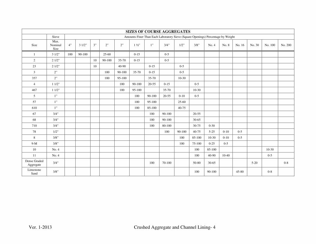
Ver. 1-2013 Crushed Aggregate and Channel Lining- 4
SIZES OF COURSE AGGREGATES
Sieve Amounts Finer Than Each Laboratory Sieve (Square Openings) Percentage by Weight
Size Max.
Nominal Size
4” 3 1/2” 3” 2” 2” 1 ½” 1” 3/4” 1/2” 3/8” No. 4 No. 8 No. 16 No. 30 No. 100 No. 200
1 3 1/2" 100 90-100
25-60
0-15
0-5
2 2 1/2"
10 90-100 35-70 0-15
0-5
23 2 1/2"
10
40-90
0-15
0-5
3 2”
100 90-100 35-70 0-15
0-5
357 2”
100 95-100
35-70
10-30
4 1 1/2"
100 90-100 20-55 0-15
0-5
467 1 1/2"
100 95-100
35-70
10-30
5 1”
100 90-100 20-55 0-10 0-5
57 1”
100 95-100
25-60
610 1”
100 85-100
40-75
67 3/4"
100 90-100
20-55
68 3/4"
100 90-100
30-65
710 3/4"
100 80-100
30-75 0-30
78 1/2"
100 90-100 40-75 5-25 0-10 0-5
8 3/8”
100 85-100 10-30 0-10 0-5
9-M 3/8”
100 75-100 0-25 0-5
10 No. 4
100 85-100
10-30
11 No. 4
100 40-90 10-40
0-5
Dense Graded Aggregate
3/4"
100 70-100
50-80 30-65
5-20
0-8
Limestone Sand
3/8” 100 90-100 45-80 0-8
Ver. 12-2013 Ditches- 1
DITCHES 1. SCOPE
This item consists of the construction of ditches (and channels) to the lines and grades depicted in the final cross-sections and Drawings. Lining materials shall meet the requirements of related sections of these Technical Specifications. Excavated rock ditches shall be constructed in accordance with details included in the plans. 2. MATERIALS
2.1. Erosion Control Blanket (ECB): Shall conform to the “Erosion Control Blanket” technical specification. 2.2. Rock Aggregate: Shall conform to the “Crushed Aggregate and Channel Lining” technical specification.
2.3. Tied Concrete Block Mat: Shall conform to the “Concrete Block Mat- Tied” technical specification. 2.4. Gabion: Shall conform to the “Gabion” technical specification. 2.5. Concrete: Shall conform to the “Concrete” technical specification. 2.6. Filter Fabric: Shall conform to the “Filter Fabric” technical specification. 2.7. Revegetation Materials: Shall conform to the “Revegetation” technical specification. 2.8. Bales: Shall conform to the “Silt Control” technical specification. 2.9. Silt Fence: Shall conform to the “Silt Control” technical specification. 2.10. Steel: Shall conform to the “Steel” technical specification. 2.11. Vehicular Grates: Shall be equivalent of Hoe of KY Type A with embedded rail frame. 2.12. Non-Vehicular Grates: Shall be 1” x 3/16” bearing bar black painted welded steel bar grating. 3. CONSTRUCTION
3.1. Subgrade Preparation: The subgrade surfaces on which filter fabric, and/or rock are to be placed shall be graded to the lines and grades shown on the Drawings and AML Standard Details. Filter fabric shall not be placed until the foundation and the subgrade surfaces have been prepared, inspected, and approved by the ENGINEER. Geo-grid may be used under
Ver. 12-2013 Ditches- 2
ditches instead of filter fabric (see Standard Details and Drawings). Do not use geo-grid or filter fabric under ditches greater than 10% slope. 3.2. Rock Aggregate Placement: Place and shape filter fabric or geo-grid under ditches less than 10% slope or as directed by the ENGINEER, AML Standard Details, and/or Drawings. The channel lining shall be carefully placed by hand or by equipment to the depths specified on the Drawings. The lining shall be constructed to the full course thickness in one operation and in such a manner as to avoid serious displacement of the underlying materials and damage to the underlying filter fabric. The rock shall be delivered and placed in a manner that will ensure that the lining, in-place, shall be reasonably homogeneous with the larger rocks uniformly distributed and firmly in contact one to another, and with the smaller rocks and spalls filling the voids between the larger rocks. Where encountering solid rock, end the slope protection at the solid rock line as shown on the Drawings or as directed by the Engineer. 3.3. Tied Concrete Block Mat: Prior to placing the tied concrete mat, prepare the sub grade area by clearing all rocks and debris 3 inches or larger. Apply seed directly to the prepared soil prior to installation of the tied concrete block mat. Install mats to the line and grade shown on the plans, AML Standard Details, and in accordance with the manufactures installation guidelines. The manufacture shall provide technical assistance during the slope preparation and installation of the flexible channel lining. 3.4. Gabion Lined Ditches: Place and shape filter fabric or geo-grid under ditches less than 10% slope or as directed by the ENGINEER, AML Standard Details, and/or Drawings. Gabion ditches include gabion anchors and concrete cutoff end treatments. 3.5. Concrete Lined Ditches: Shall be constructed to the shape and dimensions indicated on the Drawings, AML Standard or as directed by the ENGINEER. For concrete trenches requiring grates use either the vehicular or non-vehicular grate type with a steel anchor plate. Secure & anchor the grates as shown in the AML Standard Details. 3.6. Excavated Rock Ditches: Excavated Rock Ditches shall be constructed at locations shown on the plans or as directed by the ENGINEER. Excavated Rock Ditches shall be considered incidental to Earthwork if natural swales in “excavated to rock areas” exist and no additional work is required. If extremely hard rock is encountered, then a hoe ram shall be utilized to construct the ditches. The CONTRACTOR may utilize alternative equipment with the approval of the ENGINEER.
Ver. 10-2015 Drilling & Grouting for Subsidence - 1
DRILLING & GROUTING FOR SUBSIDENCE
1. SCOPE
The work shall consist of drilling a series of holes around and under the homes and filling all encountered voids and collapsed overburden with a grout/concrete mixture as shown on the Drawings or as directed by the ENGINEER. 2. GENERAL
2.1. Definitions: 2.1.1. Zone: The horizontal area influenced by grouting a hole to its final depth. 2.1.2. Void: Any subsurface opening resulting from the removal, collapse, or in-place burning of the coal seam. 2.1.3. Gob or Roof Fall Material: A mixture of roof shales and other materials, which have fallen from the roof area or have been placed in a void. 2.1.4. Coal Pillar: An unmined block of coal remaining in the coal seam. 2.1.5. Stage: A vertical subsurface interval that may include all or part of a grout column installation. 2.1.6. ASTM: American Society for Testing and Materials 2.1.7. AASHTO: American Association of State Highway and Transportation Officials 2.8. Gas Monitoring: The Contractor shall provide equipment to monitor the presence of mine gases. The equipment shall be provided with certification of it most recent inspections and testing. Mine gases include but are not limited to carbon monoxide (CO), carbon dioxide (CO2), and methane (CH4). 3. MATERIALS
3.1. Drilling Equipment: The drilling rig will be a low ground pressure rig with adjustable mast and/or articulating masts capable of drilling any compound angle off vertical between 0 and 90 degrees, with an on-board dust collection system, and pressure gauges to indicate drilling medium pressure and down pressure on the drill bit. The use of percussion drilling equipment will not be permitted, excluding down the hole air hammers for very dense formations. The drill rig shall be capable of drilling boreholes having an inside diameter capable of placing all the specified grout mixtures within the slump ranges specified, with the cuttings removed by air or water to a vertical depth of approximately 200 feet. Auger type drill tools may be used if approved by the ENGINEER.
Ver. 10-2015 Drilling & Grouting for Subsidence - 2
The on-board dust suppression or collection system will have all protective guards, locks, clamps, and other standard safety devices as originally installed by the manufacturer, or as required by OSHA. 3.2 Casing: The casing shall be Schedule 40 steel or PVC plastic casing for each hole of a sufficient length to case at a minimum through the soil zone. Schedule 40 Cellular Core or SDR Sewer pipe is an acceptable alternative. Provide airtight caps that fit securely on the casing and are made of the same material as the pipe for each casing. The pipes shall be capped with a cap made of the same material as the pipe. The caps shall fit snugly over the pipe. No type of taping to close the top of the pipes will be allowed. 3.3. Grouting Equipment: All equipment used for mixing and injecting grout shall be furnished by the Contractor and shall be maintained in first-class operating condition at all times. The equipment shall be specifically designed for grouting service, including the agitating, pumping, and injection of the cement; Flyash; sand; and aggregate grout mixes. The power, equipment, and layout of the grouting equipment shall meet all applicable requirements of local, State, and Federal regulations and codes, both safety and otherwise. The minimum equipment furnished for each grouting unit shall include:
a) A positive displacement screw-type pump. Other types of pumping equipment that is equal or better may be used, provided that the use of that equipment is specifically approved by the ENGINEER. A piston drive concrete pump shall be used for placing aggregate grout mixtures.
b) A means of monitoring the level of grout in the borehole.
c) All metal pipe and fittings required for grouting shall be furnished, cut, threaded,
fabricated, and placed by the Contractor. The Contractor shall take all necessary precautions to prevent any pipe from becoming clogged or obstructed from any cause, and any pipe, which becomes clogged, shall be cleaned out in a manner satisfactory to the ENGINEER, at the Contractor's expense.
d) Such valves, hoses, pressure gauges, pipefittings, and small tools necessary to provide a
continuous supply of grout and accurate control of the volume and pressure of grout being injected, will be provided. The pressure gauge shall be placed at the head of the grout supply pipe so that the down hole grout pressure can be accurately measured to + 1 psi. Payment shall not be made for excessive grout injected due to the inaccuracy of the Contractor's control.
e) No restriction in the grout line from the pump to and down the hole will be allowed. The size of the line will be the same size with no reducers or restrictions being used in the pipeline. The pressure gauge must be placed at the top of the hole. The Contractor is responsible for selecting a pipe size, that will allow him to accomplish the objectives of this contract, which includes filling all mine level voids, roof fall material, and mine gob
Ver. 10-2015 Drilling & Grouting for Subsidence - 3
material with any of the grout mixes indicated in the Grout Mixes section of these specifications. Any grout hole that is lost or damaged due to mechanical failure of equipment, or inadequacy of grout supply, shall be replaced by another hole drilled by the Contractor at the Contractor's expense. The Contractor shall also be responsible for any expenses that are incidental to replacement of the lost or damaged hole. All of the above-listed equipment, powered by internal combustion engines, shall be equipped with spark-arrester-type mufflers capable of noise suppression for work in residential areas. The Contractor shall take all necessary precautions to prevent any pipe from becoming clogged or obstructed from any cause, and any pipe that becomes clogged shall be cleaned out in a manner satisfactory to the ENGINEER, at the Contractor’s expense.
Adequate valves will be required at the pump and at each hole to ensure control, by-
pass and shut-off capabilities as required by the ENGINEER. The equipment and lines shall be prevented from becoming fouled by either constantly circulating the grout or periodically flushing out the system with water.
f) Mechanical or hydraulic packers specifically designed for use in pressure grouting operations.
3.4. Grout Mix Materials: 3.4.1. Certifications: Upon request, the Contractor shall supply the ENGINEER with letters of certification that all materials to be used meet the requirements of this technical specification prior to commencing grouting activities. The Contractor shall notify the ENGINEER a sufficient time in advance of the beginning of grout mixing so that the ENGINEER can take samples or run tests, as deemed necessary. 3.4.2. Water: The water used in the grout shall be furnished by the Contractor and shall be clean and free from injurious amounts of sewage, oil, acid, alkali, salts, organic matter, or other foreign solids deemed by the ENGINEER as deleterious to the grout mix. 3.4.3. Cement:
(1) Cement used in grout shall meet the requirements ASTM C150-84 Type I or II. (2) The cement shall be free from lumps due to storage. In the event the cement is
found to contain lumps or foreign matter in an amount the ENGINEER considers deleterious to the grouting operations, screening through U.S. Standard 100 mesh screen shall be required. No additional payment shall be made for such screening of old cement.
Ver. 10-2015 Drilling & Grouting for Subsidence - 4
3.4.4. Sand: Sand shall be supplied and handled by the Contractor. The sand shall consist of hard, dense, durable, uncoated rock fragments obtained from a river or quarry with not more than 5% of any deleterious substances. Frack or eolian (windblown) sand is preferred. The fineness of the sand required for grouting shall be as follows: 100% passing #4 with 15% and 25% passing a No. 200 sieve. 3.4.5. Coarse Aggregate: Type "A" coarse aggregate shall be supplied by the Contractor. The aggregate shall consist of hard, dense, durable uncoated gravel or crushed stone and shall be free of harmful amounts of clay, silt, vegetation, or other substances determined to be deleterious. The grain size distribution of the aggregate shall be as follows (equivalent to ASTM#7):
% Finer by Weight Sieve Size 100 3/4 in.
90-100 2 in. 40-70 3/8 in. 0-15 No. 4
An alternative gradation may be used subject to the approval of the ENGINEER. Prior to use of the alternative aggregate in a grout mix, the Contractor shall submit to the ENGINEER a gradation of the material to be used and receive written approval for its use from the ENGINEER. Crushed stone may be required by the ENGINEER upon request.
3.4.6. Flyash: Flyash shall conform to mineral admixture Class F, but is not required to meet the uniformity and moisture requirements of that specification. The moisture content shall not exceed 15%, unless the Contractor can provide test data to the ENGINEER from an independent, qualified laboratory, which documents that the increased moisture will not negatively influence the grout characteristics and/or strength. The maximum Loss of Ignition
will be 6%. Black or brown Fly ash will not be allowed unless certified lab results show the
loss of ignition to be 6% or less. Testing methods and calculations used to determine
percentage of loss of ignition shall be in accordance with ASTM C311, Subsections 13 and
14. The Contractor shall be solely responsible for any costs associated with these tests.
The Fly ash shall be stored so that it will not deteriorate from moisture, weather, or other causes. If the Flyash is found to contain lumps that the ENGINEER considers deleterious to the grouting operation, screening through a U.S. Standard 100 mesh screen will be required. No additional payment shall be made for such screening. 3.4.7. Accelerator: Accelerator admixtures shall conform to ASTM C494-82 chemical admixtures for concrete; Type E - water reducing, accelerating, and admixtures shall be added to the grout mix only with the approval of the ENGINEER. 3.5. Grout Mixes: The water-cement-Flyash ratio, as well as the ratio of other materials, shall be varied by the ENGINEER to meet the characteristics of each hole as revealed by the drilling and grouting
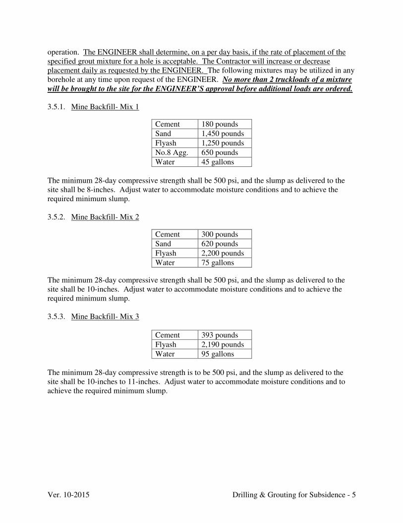
Ver. 10-2015 Drilling & Grouting for Subsidence - 5
operation.. The ENGINEER shall determine, on a per day basis, if the rate of placement of the specified grout mixture for a hole is acceptable. The Contractor will increase or decrease placement daily as requested by the ENGINEER. The following mixtures may be utilized in any borehole at any time upon request of the ENGINEER. No more than 2 truckloads of a mixture
will be brought to the site for the ENGINEER’S approval before additional loads are ordered.
3.5.1. Mine Backfill- Mix 1
Cement 180 pounds
Sand 1,450 pounds
Flyash 1,250 pounds
No.8 Agg. 650 pounds
Water 45 gallons
The minimum 28-day compressive strength shall be 500 psi, and the slump as delivered to the site shall be 8-inches. Adjust water to accommodate moisture conditions and to achieve the required minimum slump.
3.5.2. Mine Backfill- Mix 2
Cement 300 pounds
Sand 620 pounds
Flyash 2,200 pounds
Water 75 gallons
The minimum 28-day compressive strength shall be 500 psi, and the slump as delivered to the site shall be 10-inches. Adjust water to accommodate moisture conditions and to achieve the required minimum slump. 3.5.3. Mine Backfill- Mix 3
Cement 393 pounds
Flyash 2,190 pounds
Water 95 gallons
The minimum 28-day compressive strength is to be 500 psi, and the slump as delivered to the site shall be 10-inches to 11-inches. Adjust water to accommodate moisture conditions and to achieve the required minimum slump.
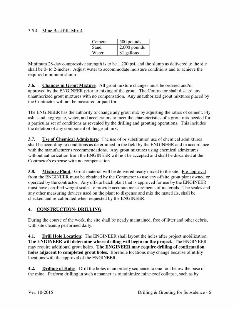
Ver. 10-2015 Drilling & Grouting for Subsidence - 6
3.5.4. Mine Backfill- Mix 4
Cement 500 pounds
Sand 2,000 pounds
Water 81 gallons
Minimum 28-day compressive strength is to be 1,200 psi, and the slump as delivered to the site shall be 0- to 2-inches. Adjust water to accommodate moisture conditions and to achieve the required minimum slump. 3.6. Changes in Grout Mixture: All grout mixture changes must be ordered and/or approved by the ENGINEER prior to mixing of the grout. The Contractor shall discard any unauthorized grout mixtures with no compensation. Any unauthorized grout mixtures placed by the Contractor will not be measured or paid for. The ENGINEER has the authority to change any grout mix by adjusting the ratios of cement, Fly ash, sand, aggregate, water, and accelerators to meet the characteristics of a grout mix needed for a particular set of conditions as revealed by the drilling and grouting operations. This includes the deletion of any component of the grout mix. 3.7. Use of Chemical Admixture: The use of or substitution use of chemical admixtures shall be according to conditions as determined in the field by the ENGINEER and in accordance with the manufacturer's recommendations. Any grout mixtures using chemical admixtures without authorization from the ENGINEER will not be accepted and shall be discarded at the Contractor's expense with no compensation. 3.8. Mixture Plant: Grout material will be delivered ready mixed to the site. Pre-approval from the ENGINEER must be obtained by the Contractor to use any offsite grout plant owned or operated by the contractor. Any offsite batch plant that is approved for use by the ENGINEER must have certified weight scales to provide accurate measurements of materials. The scales and any other measuring devices used on the plant to dispense and mix the materials, shall be checked and re-calibrated when requested by the ENGINEER. 4. CONSTRUCTION- DRILLING
During the course of the work, the site shall be neatly maintained, free of litter and other debris, with site cleanup performed daily.
4.1. Drill Hole Location: The ENGINEER shall layout the holes after project mobilization. The ENGINEER will determine where drilling will begin on the project. The ENGINEER may require additional grout holes. The ENGINEER may require drilling of confirmation
holes adjacent to completed grout holes. Borehole locations may change because of utility locations with the approval of the ENGINEER. 4.2. Drilling of Holes: Drill the holes in an orderly sequence to one foot below the base of the mine. Perform drilling in such a manner as to minimize mine-roof collapse, such as by
Ver. 10-2015 Drilling & Grouting for Subsidence - 7
reducing down pressure, etc., directly above the mine. The Contractor shall be responsible for drilling a plumb hole. Drill the holes with bits and stabilizers that will provide full-diameter, straight holes. Diameter of holes and casing shall be large enough allow the specified grout mixes to be properly placed. 4.3. Water in Drill Holes: Contain and filter water encountered in the drilling process and carried to the surface with cuttings by the use of straw bales. Discharge water in such a manner, subject to approval of the ENGINEER, with no water directed toward the residence. Cuttings and dust sludge shall be cleaned daily from the hole area after drilling. Water discharged from the immediate work area shall meet all applicable Federal and State effluent limitations. 4.4. Casing Holes: Protect each hole from caving and/or becoming clogged or obstructed. Grout holes drilled through soil overburden shall have a casing keyed into rock sufficient to exclude all overburden and to be watertight. Holes drilled thorough the soil zone shall be sized to allow casing placement without excessive force. The casing must fall freely down into the hole with only minimum pressure. This casing shall then be capped. Any hole that becomes clogged or obstructed, for any reason, before completion of operations, shall be cleaned out or replaced at the Contractor's expense. Further, any incidental expenses required for cleaning out a hole or providing a replacement hole shall be the responsibility of the Contractor. The casing shall extend no more than two feet above the ground surface and shall be capped. Casing shall be left in the hole until the completion of grouting operations at that hole, and shall then be removed or left in place. Drill holes in the driveway shall be cut flush with the pavement and protected with a steel cap or other acceptable method, which will protect the hole from being damaged by vehicular traffic. A borehole must be washed, within 24 hours of drilling, to remove mud and cuttings adhering to the boring sidewalls. The method and amount of water used to wash the boreholes will be determined by the ENGINEER. For example, washing may be done by using water from a hose directed into the top of the hole. 4.5. Drilling Holes through Rock: Plug or non-coring bits may be used. Upon completion of drilling a hole, the hole shall be temporarily capped with a secure cap and otherwise protected from entry of foreign material until grouting operations are initiated. 4.6. Completion of Holes: Cap and protect all drilled and cleaned holes from obstruction by debris until completion of the grouting of the hole. Any required cleaning of the hole after initial drilling and cleaning shall be at the Contractor's expense. The pipe casing can be removed or left in place. Casing grouted into place shall be cut off at a minimum distance of one foot below the surrounding surface elevation per the ENGINEER's approval. No additional payment shall be made for casing grouted into place. The Contractor on a daily basis shall remove all unsuitable material from the site. Unsuitable material shall include, but not be limited to, concrete, drill cuttings, old pavement, spilled grout,
Ver. 10-2015 Drilling & Grouting for Subsidence - 8
aggregate, and soils designated by the ENGINEER as unsuitable for backfill. The compensation for this work shall be included in other bid items of the contract. The top one foot shall be replaced with material the same as, or similar to, the surface material through which the borehole was drilled. Backfill materials, methods, and material substitutions shall be subject to approval of the ENGINEER. 4.7. Borehole Logs: The Contractor shall keep accurate logs of boreholes drilled. Each log shall include, at a minimum, the following information:
(1) Project name, contract number, boring location, boring number, diameter of hole, driller's name, date, time started, and time completed.
(2) Complete listing by depth recorded in feet and tenths of feet of each overburden strata
and description of each void and broken zone in the overburden, height of mine void, thickness of coal, and total depth of hole.
(3) Size and depth of casing installed and whether casing was removed or left in place. (4) Information regarding relevant events during the drilling, including depth where
groundwater was encountered, where drill water or air was lost, and venting gases encountered, etc.
(5) If requested by the ENGINEER, the Contractor shall record accurate water levels,
borehole depth, and methane concentrations in each borehole every day for the duration of the project.
The fact that an inspector shall be present and keeping a record of the drilling shall not relieve the Contractor from the requirements of keeping an accurate log as described above. A legible, handwritten copy of the borehole logs shall be presented to the ENGINEER within 24 hours of the drilling of any borehole. Typewritten borehole logs shall be presented to the ENGINEER at the end of each week during which drilling has taken place. 5. CONSTRUCTION- GROUTING
5.1. Grout Placement: Placement of grout mixtures shall be in accordance with these specifications as to depth, rate, ratios, qualities and quantities, or any combination of these requirements as indicated or otherwise established by the ENGINEER. Unless determined otherwise by the ENGINEER, all placements of grout mixtures within the boreholes shall be as follows for the particular conditions described. All grout mixtures shall be pumped through a grout injection pipe that has been placed at a place within the overburden as determined by the ENGINEER. Holes with grout takes in excess of 32 cubic yards per day will be grouted in stages, as approved by the ENGINEER. If the grout is being pumped into collapsed or gob material or if pressure is building within the hole than additional grouting above
Ver. 10-2015 Drilling & Grouting for Subsidence - 9
the 32-yard stage will be allowed. The grout shall be allowed to set for 12 hours between stages. Daily grout placement shall be limited to 32 cubic yards per borehole, unless otherwise reduced or increased by the ENGINEER. On holes that are under pressure in collapsed material the 32 CY per hole will be waived. Limits on grout for these types of holes will be determined on a hole-by-hole basis by the ENGINEER. Any borehole that had grout placed into it but was not filled, shall be flushed with water
within 30 minutes, or a period acceptable to the ENGINEER, after grout placement. The
amount of water used, the time spent, and method of the flushing will be subject to
approval by the ENGINEER. In addition, a minimal amount of water, to be approved by the ENGINEER, can also be used to lubricate grout lines and to clear the grout injection pipe. The Contractor shall transport via pipeline the grout into the borehole in such a way as to not coat or foul the borehole until the mine level void, roof fall material, and/or mine gob is filled. The grout line from the pump to the hole shall not have any restrictions of any kind. For example, if a three-inch line is selected to transport the material from the pump the contractor must continue the three-inch pipe all the way to and down the hole to the discharge end. Upon ENGINEER request, a measurement shall be taken to determine the depth to the top of the grout. Additional grout shall be injected if, in the opinion of the ENGINEER, the grout has dropped to a depth that may indicate that additional voids exist within the grout hole. 5.2. Structure Monitoring: The Contractor shall provide monitoring of structures within the project area, and other structures as determined by the ENGINEER, during all grouting activities. The purpose of the monitoring is to detect any potential for damages due to grout migration. The Contractor shall be responsible for all damages that occur due to the Contractor's
failure to comply with these contract specifications and/or failure to use due care.
The loss of packers for various reasons is anticipated during the course of grouting
procedure. The Contractor will not be reimbursed for packer loss during project activity. 5.3. Grout Conditions: 5.3.1. Grouting Gob-Filled Voids and Roof Fall Material (RFM): A hole shall be drilled through the overburden, RFM and/or mine gob to a depth of one foot below the base of the mined coal seam. A grout supply pipe, equipped with a discharge tip (if requested by the ENGINEER) and a packer, shall be extended through the drilled hole to a point in the overburden as determined by the ENGINEER. A packer may be set at the ENGINEER's approved elevation above the roof of the mine. If intact bedrock is not present within 10 feet of the mine, the packer may be set within intact bedrock as close as possible to the roof of the mine. The depth of the packer setting must be approved by the ENGINEER prior to its placement in the hole. A volume of grout Mix No. 1 (determined by the ENGINEER) shall be then forced under pressure (determined by the ENGINEER) into the gob or RFM. If large takes are encountered, the mix shall be changed, thickened and, if the take persists, aggregate shall be added.
Ver. 10-2015 Drilling & Grouting for Subsidence - 10
5.3.2. Grouting Open Voids (two feet or greater): If an open void two feet or greater is encountered (as determined by the ENGINEER), the grout supply pipe shall be placed down to an elevation determined by the ENGINEER. (Any gob and/or roof fall material underlying the void shall be grouted in accordance with Item No. 5.4.) A volume of Grout Mix No. 3 (or other mixture as determined by the ENGINEER) shall be introduced into the void via pressure, as determined by the ENGINEER. If the grout take is not excessive (as determined by the ENGINEER), the cavity shall be filled in stages with a maximum of 32 cubic yards per hole/day. The grout shall be allowed to set for 12 hours between each stage. If large takes are encountered, as determined by the ENGINEER, the mix shall be thickened. The ENGINEER is authorized to designate the use of Mix Nos. 2 and/or 4 for grouting if excessive takes persist. The amount of the mix injected will be determined by the ENGINEER on a hole-by-hole basis. . 5.3.3. Grouting In-Place Coal: If neither voids, mine gob, nor roof fall material are encountered, a grout pipe shall be inserted, and the borehole shall be backfilled using Grout Mix No. 1 to a level three feet above the coal seam. After the initial set of the grout (12 hours), the rock overburden shall be grouted in accordance with TS No. 5.8. 5.3.4. Grouting Open Voids (less than two feet): Open voids, less than two feet in height, shall be grouted in accordance with TS No. 5.4. 5.3.5. Grouting Rock Overburden: Upon ENGINEER request, the grout pipe shall be inserted and the borehole shall be backfilled with a volume of Grout Mix No. 1 to a level immediately above the roof of the mine. After the initial set of the grout occurs at mine level, a down hole packer may be placed above the set grout at an ENGINEER determined elevation. Nitrogen filled or equivalent packers shall be used to reduce the risk of explosion. Oxygen filled packers are not permitted. Grouting with Mix No. 1 shall be continued until determined necessary by the ENGINEER. In general, pressures at the ground surfaces shall not exceed 1/2 psi per foot overburden above the packer location. The borehole above the final packer set elevation may be filled by gravity flow. Another stage of gravity grouting may be necessary to refill the hole to its former level after the grout is allowed to set for 16 hours. 5.3.6. Lost Grout Hole: Any grout hole that is lost or damaged due to Contractor-related causes shall be replaced by the Contractor, at the Contractor's expense, in a manner and location acceptable to the ENGINEER. Any incidental expenses incurred in replacing the grout hole shall be borne by the Contractor. 5.3.7. Grout Sample Testing: Grout may be sampled on a periodic basis by DAML. Test for compressive strength and a petrographic analysis of the sampled components shall be done by a qualified laboratory secured by the government. The test samples shall be taken by the ENGINEER or the onsite inspector. These tests will be random with no warning given to the contractor prior to the samples being taken. 5.3.8. Records and Forms: During the progress of the work, the Contractor shall supply, upon the ENGINEER's request, two copies of all records and forms pertaining to the quantity and quality of material delivered to the site and grout sample test results. The Contractor shall submit to the ENGINEER daily labor and material records.

Ver. 10-2015 Drilling & Grouting for Subsidence - 11
The Contractor and the DAML monitor shall confer daily regarding the quantity of materials delivered and/or placed in the course of the work. Any disagreement shall be brought to the attention of the ENGINEER within 24 hours. The Contractor shall sign off on the monitor's daily construction logs signifying agreement or disagreement daily.
Ver. 12-2014 Drop / Junction Boxes- 1
DROP / JUNCTION BOXES
1. SCOPE
This work consists of construction of drop-box inlets and/or junction boxes at locations shown on the Drawings and as directed by the ENGINEER. The drop boxes and/or junction boxes shall be fabricated in accordance with the AML Standard Details and/or Drawings. Units may be cast in-place for pre-cast. Pre-cast units shall be accompanied by manufacturer’s certification showing compliance with these requirements. 2. MATERIALS
2.1. Concrete: Shall be Class A concrete conforming to the “Concrete” technical specification. This includes concrete for the boxes, lids (where appropriate), and aprons (when required). 2.2. Reinforcing Steel: Shall be 60 KSI steel conforming to the “Steel” technical specification. 2.3. PVC Plastic: Shall be “Drain” and/or “Inline” systems manufactured from PVC pipe stock utilizing a thermo-molding process formed conforming to ASTM D1784 “Standard Specification for Rigid Polyvinyl Chloride (PVC) Compounds and Chlorinated Polyvinyl Chloride (CPVC) Compound.” 2.4. Backfill: Shall conform to the “Crushed Aggregate and Channel Lining” technical specification. 2.5. Grates: Shall be ductile iron made specifically for each basin with a bottom flange that closely matches the size and shape of the surface drainage inlet. Grates and covers shall be provided painted black. 2.6. Connections: Shall be from the box structures manufacturer. These include watertight seals, adapters, “tee,” risers, and other pieces associated with the box system. 3. CONSTRUCTION
Construct drop/ junction boxes in accordance with the AML Standard Details and as shown on the Drawings and at elevations and locations established by the ENGINEER. Boxes that may receive traffic will have a compacted DGA base and concrete apron poured around the inlet.
Ver. 1-2013 Earthwork- 1
EARTHWORK 1. SCOPE
The work shall consist of the required removal and proper utilization of all earthen materials and the shaping and finishing the area(s) to the required lines and grades as shown on the Drawings or as directed by the ENGINEER. 2. MATERIALS
2.1. Excavated Materials: All excavated materials shall be unclassified. It is anticipated that the majority of the material to be removed will consist of a mixture of loose, unconsolidated soil, vegetative debris and rock. It may also consist of residual soil and “mine spoil” produced from past mining operations. Also, large boulders may exist within the excavation areas. 2.2. Refuse: Shall be defined as coal, coal waste, rock and other debris that was produced and discarded by past mining practices. Some areas will have a higher content of coal then others depending on the mining method. Generally the material is sparsely vegetated and acidic. Some areas may be burning or have burned in the past. 2.3. Rock: Shall be defined as large consolidated fragments (boulders) or consolidated bedrock material that cannot be removed by normal excavation methods and must be removed by means such as blasting, ripping, hoe ram or other methods used in the construction industry that are generally accepted as methods to remove rock. 2.4. Cover Material: Acceptable cover materials should have a brown matrix color, soil water pH greater than 4.5, potential acidity of less than 2 tons calcium carbonate (CaCO3) equivalent per 1,000 tons of material, and less than 50% clay content. 2.5. Agriculture Limestone: Shall meet the requirements of the “Revegetation” technical specification.
3. CONSTRUCTION
3.1. Conduct of Work: The reclamation approach intent is to provide a lasting, stable configuration. The CONTRACTOR is required to exercise care to avoid intermediate site conditions which may result in unstable conditions during the construction process. 3.2. Gradework Areas: Grade areas to the lines and grades indicated on the Drawings or as directed by the ENGINEER to promote positive drainage. 3.3. Blasting: 3.3.1. General: Blasting when permitted shall be done only to the depth, amount and extent, and in such locations, as approved by the ENGINEER. Blasting operations shall comply with all applicable State and Federal laws. Neither the COMMONWEALTH nor the ENGINEER shall
Ver. 1-2013 Earthwork- 2
assume any liability through approval of the CONTRACTOR'S blasting plan or methods of blasting. Such approval will not relieve the CONTRACTOR of his responsibility in the blasting operation, and no payment will be made for any necessary extra excavation below or outside of the limit lines designated by the ENGINEER, or modifications thereof, due solely to injury caused by over-shooting, improper blasting, or carelessness on the part of the CONTRACTOR.
A licensed blaster licensed in the Commonwealth shall be on site at all times dealing with all blasting activities such as pre-blast survey, pre-blast preparation, blasting and post–blast activities. 3.3.2. Pre-Blast Survey: A pre-blast survey shall be conducted on all dwellings or structures located within 1/2 mile radius of any proposed blasting activity. The survey shall be the responsibility of the CONTRACTOR and shall consist of an assessment of the conditions of each dwelling or structure and documentation of any pre-blasting damage and other physical factors that could reasonable be affected by the blasting. Assessments of structures such as pipes, cables, transmission lines, and other water systems shall be limited to surface condition and readily available data. Selected water wells shall be monitored for both quantity and quality during the initial survey and throughout the duration of blasting operations, at no additional cost to the COMMONWEALTH. 3.3.3. Use of Explosives: The transportation, handling, storage, and use of dynamite and/or other explosives shall be directed and supervised by a person of proven experience and ability in blasting operations. All blasting operations shall be in accordance with all applicable local, State, and Federal laws. Before any explosives are brought on the job, permission to do so shall be obtained from the ENGINEER.
3.4 Material Removal: Material removal shall include excavation to the designated depths, transportation of removed materials from points of removal to the points of final use and the shaping and finishing of all areas to the required lines and grades as shown on the Drawings or as directed by the ENGINEER. All boulders encountered during the construction, which are too large to be transportation to the waste area may be moved to the stable area within the project limits and buried on site with a minimum of 2 feet cover or they may be reduced to a size that can be transported to the waste area or other areas designated on the Drawings or as directed by the ENGINEER. The boulders may be reduced by the use of hoe-ram as specified by these Technical Specifications or other methods approved by the ENGINEER. Utilize material removal techniques that are generally considered conducive to retaining stability. This includes, but is not limited to, working slopes from the top to the bottom to preclude undermining. Once disturbed, all earthwork areas shall be brought to the design template as soon as practicable and shall be protected in accordance with the “Revegetation” technical specification as the work progresses. 3.5. Sheeting and Bracing: Sheeting and bracing as may be required to safely support the sides of excavations shall comply with the safety precautions as outlined in current and accepted safety manuals, such as "Associated General Contractors Manual of Accident Prevention in Construction". Where sheeting and bracing are necessary to prevent caving of the walls of excavation and to safeguard the workers, dig the excavations to such widths that proper
Ver. 1-2013 Earthwork- 3
allowance is made for the space occupied by the sheeting and bracing. Perform the additional excavation required, furnish and place the necessary sheeting and bracing, and remove same as the excavation is filled at your own expense. 3.6. Cover Material Harvesting Areas: All limits are to be approved by the ENGINEER prior to any work efforts (site prep, silt control, earthwork, etc.) commencing. Once excavation work is completed within a designated harvesting area, it shall be graded as directed by the ENGINEER. No areas shall have final slopes steeper than a 2.5:1 nor shall trenches and/or pits be left as a final grade. All disturbed areas shall be revegetated as soon as practical in accordance with the “Revegetation” technical specification. Diversions shall be set at least every 50 vertically and once across the top of the slope. The ENGINEER may require foundation benching prior to final grading as part of the cover material earthwork efforts. See the AML Standard Details for typical final slope configurations. 3.7. Material Placement: No material shall be placed in any area until the area has been stripped as specified and the ENGINEER has approved the foundation. The CONTRACTOR shall maintain and protect areas of fill in a satisfactory condition at all times until completion and acceptance of all work under the Project. If, in the opinion of the ENGINEER, the hauling equipment causes horizontal shears of slicken sides, rutting, quaking, heaving, cracking, or excessive deformation of fills, the CONTRACTOR shall limit the type, load or travel speed of the hauling equipment on the areas of fill. During material placement, the CONTRACTOR shall remove from the areas of fill any material, which the ENGINEER considers objectionable, and shall also dispose of such material and refill the areas as directed, all at no additional cost to the COMMONWEALTH. 3.7.1. Stockpiles: In order to provide a stable temporary storage of soil that controls the potential for erosion and sedimentation:
a) The footprint of the stockpile must be sized to accommodate the anticipated volume of material and based on a side slope ratio no steeper than 2:1. Benching may be required.
b) Runoff from the stockpile area must drain to a suitable sediment control practice. c) Access the stockpile area from the upgrade side. d) Clear water runoff into the stockpile area must be minimized by use of a diversion device
such as an earth dike, temporary swale or diversion fence. Provisions must be made for discharging concentrated flow in a non-erosive manner.
e) Where runoff concentrates along the toe of the stockpile fill, an appropriate erosion/sediment control practice must be used to intercept the discharge.
f) If the stockpile is located on an impervious surface, a liner should be provided below the stockpile to facilitate cleanup. Stockpiles containing contaminated material must be covered with impermeable sheeting.
g) The stockpile area must continuously meet the requirements for vegetative establishment. Side slopes must be maintained at no steeper than a 2:1 ratio. The stockpile area must be kept free of erosion. If the vertical height of a stockpile exceeds 20 feet for 2:1 slopes, 30 feet for 3:1 slopes, or 40 feet for 4:1 slopes, benching must be provided.
Ver. 1-2013 Earthwork- 4
3.7.2. Cover Material Placement: Distribute earthen cover material over unsuitable materials (coal refuse, slurry, impoundments, etc.) in a manner such that the fill will be free from voids, pockets, and bridging of material. The Drawings and/or Special Conditions may require the placement of an agricultural limestone barrier prior to placement of cover material. The combined material removal and placement operations shall be such that the material, when compacted, will be blended sufficiently to ensure the best practicable degree of compaction and stability. Successive loads of materials shall be dumped to produce the best distribution. No material placed in the fill area by dumping in piles or windrows shall be incorporated in a layer in that position, but shall be moved and spread by blading or similar approved methods. The thickness of layers placed before compaction shall be as designated in the Drawings and/or Special Conditions. A minimum 2 foot final cover depth is required over acidic materials. 3.7.3. Waste Areas: Materials placed in designated fill areas shall consist of those suitable materials, as determined by the ENGINEER, which are removed in the process of achieving the templates shown on the Drawings. Vegetative debris shall not be placed in the designated waste areas. It shall be the CONTRACTOR'S responsibility to dispose of unsuitable materials in accordance with the provisions of the Specification. The ENGINEER shall inspect and approve the disposal sites before material is placed in a given area. Any boulders, which are transported to a waste area shall be buried a minimum of two feet under the final grade or reduced to a size that will not affect the fill operation. On all waste areas excavated topsoil and/or select material shall be uniformly distributed as a final cover material. The waste area(s) shall be revegetated in accordance with the “Revegetation” section of these Technical Specifications. Old strip mine benches to be used as waste areas must be sampled every 50’ feet to determine the presence of rock under the material that now exists. Once the rockline has been established and the edge of rock determined, the contractor upon approval from the Engineer shall begin placement of material on the bench. Material placed on the bench shall be at least 10’ from the edge of the rockline determined by the field sampling and approved by the ENGINEER. 3.8. Foundation Benching: Excavate benches in all waste areas where the original ground slope beneath the fill is 15% or greater. Keep the area free from water or unacceptable material after the placement operations have started. Where depicted or described in the Drawings, an average depth of 18 inches of topsoil shall be stripped from the area and stockpiled at locations designated by the ENGINEER; the excavated topsoil shall be uniformly redistributed once all backfilling efforts have been completed. When soil material is placed against sloping sides of excavations, slopes of old embankment, or natural slopes, the old material shall be cut or broken by machine or hand methods approved by the ENGINEER, until it shows the characteristic color of moist material. The equipment shall then compact both materials, bonding them together.
Ver. 1-2013 Earthwork- 5
3.9. Moisture Control: During the compaction operation, the surface of the fill area and the materials being placed shall be maintained within the moisture content range required to permit proper compaction to the density specified herein. The moisture content shall be controlled in the following manner:
a) When material deposited on the fill is too dry, the CONTRACTOR shall be required to sprinkle each layer and obtain uniform moisture distribution in the layer by disking, blading, or other approved methods. The amount of water applied shall be accurately controlled so that free water will not appear on the surface during or subsequent to compaction operations.
b) Material deposited in fill areas that is too wet shall be removed or spread and permitted to
dry, assisted by disking or blading if necessary, until the moisture content is reduced to the specified limits.
c) When the top surface of a layer becomes too dry or too smooth to permit suitable bond
with the subsequent layer, the CONTRACTOR shall loosen the material by scarifying, disking, or using other suitable equipment in an approved manner until the in-place material shows the characteristic color of moist material to a sufficient depth to provide a satisfactory bonding surface as determined by the ENGINEER. The ENGINEER may also require that the loosened material be moistened, to acceptable moisture content as generally determined by visual inspection, and the material reworked, prior to compacting the material to the specified density.
d) Adjustments of moisture content shall be made based on determination of moisture by
field tests as construction progresses. 3.10. Special Handling: Mixing, segregation, and/or other special handling of excavated materials may be required to avoid: concentrations of unsuitable materials in fill areas; development of lenses that may contribute to instability; and/or unacceptable voids, pockets, and bridging. Toward this objective, the CONTRACTOR may be required to excavate materials in a sequence which will, in the ENGINEER'S opinion, provide the best control for segregating extremely moist, weak, rocky, or other undesirable materials until same can be dried and/or otherwise properly incorporated into fill areas. Materials consisting predominantly of non-friable rock, when placed in areas of fill shall not be dumped in final position, but shall be distributed in a manner that will ensure placement so that voids, pockets, bridging and settlement, or shifting are held to a minimum. Concentrations of predominantly rock materials, where the largest fragments do not exceed 1-1/2 cubic feet in size and the overall material sizes are generally in a well distributed range, may be placed in 2 foot thick layers as approved by the ENGINEER. Larger rocks, particularly those approaching boulder proportions, are to be isolated in the fill and material compacted around them as otherwise required herein. Rocks of sizes and/or gradations outside or between the ranges described are to be handled as directed by the ENGINEER on a case-specific basis.
Ver. 1-2013 Earthwork- 6
3.11. Compaction: Compaction requirements for all AML projects will fall into one of three categories, Maximum Compactive Effort, Moderate Compactive Effort, or Minimum Compactive Effort. If the level of compactive effort is not designated elsewhere in the
Specifications or on the Plans, then the fill area shall receive a Moderate Compactive
Effort.
a) Maximum Compactive Effort (Critical Use Areas): Areas designated to receive maximum compactive effort shall have materials placed in 12 inch maximum horizontal lifts with an in-place moisture content within 3% of the optimum moisture content (ref. ASTM D-698). They shall be compacted with a minimum of 4 passes with a sheepsfoot roller with a foot contact area of 10-14 square feet and foot contact pressure between 150-250 psi. Should this method not provide sufficient compaction to achieve 95% of the materials maximum dry density with an in-place moisture content within 3% of the optimum moisture content (ref. ASTM D-698), then additional compactive effort and/or shallower lifts shall be required. In-place density and moisture tests shall be performed, utilizing methods outlined in ASTM D-2922, for every lift of material placed. The number of tests per lift shall be as determined by the ENGINEER. The ENGINEER shall be responsible for taking compaction tests.
b) Moderate Compactive Effort (Non-Critical Use Areas): Areas designated to receive
moderate compactive effort shall have materials placed in 12 inch maximum horizontal lifts, spread, and compacted with successive passes of dozers or other tracked equipment. The satisfaction of the compaction/moisture control efforts shall be based on continuous assessments of the color, moistures, and overall suitability of materials slated for placement. The equipment to be used for spreading and compaction; as well as the reaction of the in-place materials to the applied loadings to ensure that pumping, weeping, heaving, and other conditions normally accompanying or indicating unacceptable compaction or moisture levels are not present. In the event of conflicts between the CONTRACTOR and ENGINEER, or persistence of placement/compaction problems, density and moisture testing will be initiated. Sufficient compaction shall be required to achieve 90% of the material’s maximum dry density with in-place moisture content within 3% of the optimum moisture content and/or the ENGINEER may require a modification in the CONTRACTOR'S handling, placement, or compaction procedures.
c) Minimum Compactive Effort (Non-Critical Use Area): Areas designated to receive
minimum compactive effort shall have materials placed in 24 inch maximum horizontal lifts and spread and compacted with successive passes of dozers, track equipment, or rubber tired hauling equipment. Uniform compaction must be obtained throughout each lift. Moisture levels shall be monitored to ensure adequate compaction. If satisfactory compaction is not being achieved, then the ENGINEER may require to CONTRACTOR to meet compaction requirements established under moderate compactive effort.
Such testing, or the lack thereof, does not relieve the CONTRACTOR from ensuring that all lifts receive the appropriate amount of compactive effort. In-place material not meeting these specifications will be rejected and shall be removed and/or reworked until satisfactory results are obtained.
Ver. 1-2013 Earthwork- 7
3.12. Tolerances: Material removal shall include excavation to the designated depths, transportation of removed materials from points of removal to points of final use, and the shaping and finishing of all areas. Material removal carried below the indicated depths, except when directed by the ENGINEER, shall be replaced with material satisfactory to the ENGINEER. Additional payment will not be made for unauthorized material removal or for any backfilling necessitated thereby. All areas shall be constructed to the lines, grades, and cross-sections indicated on the Drawings, unless otherwise directed by the ENGINEER. Make every reasonable effort to construct the project uniformly. Tolerances, which will be allowed, before changes will be made in the quantities to be paid or before reworking of the constructed item is required, are as follows:
a) The design intent is to stabilize the area(s) and to leave a free draining uniform surface suitable for revegetation. The nature of the project does not lend itself very well to the establishment of numerical standards for permissible deviations from the templates and lines shown on the Drawings. A work area will generally be accepted when, in the opinion of the ENGINEER, the design intent has been achieved. However, in the event problems arise, the ENGINEER may require that the finished grades not deviate more than 1 foot from the neat lines shown on the Drawings.
b) No payment will be made for any earthwork performed outside the limits shown on
the Drawings or those approved by the ENGINEER. No extra material shall be removed or placed outside of these limits without permission.
3.13. Acceptance: The ENGINEER will not accept any area as being satisfactorily complete if an adjacent work area remains in a condition, which may cause damage to the subject area. Once the ENGINEER has accepted an area, the COMMONWEALTH will then be responsible for interruptive slides, slippages, and/or erosion.
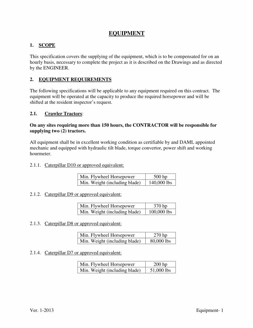
Ver. 1-2013 Equipment- 1
EQUIPMENT
1. SCOPE
This specification covers the supplying of the equipment, which is to be compensated for on an hourly basis, necessary to complete the project as it is described on the Drawings and as directed by the ENGINEER. 2. EQUIPMENT REQUIREMENTS
The following specifications will be applicable to any equipment required on this contract. The equipment will be operated at the capacity to produce the required horsepower and will be shifted at the resident inspector’s request. 2.1. Crawler Tractors: On any sites requiring more than 150 hours, the CONTRACTOR will be responsible for
supplying two (2) tractors. All equipment shall be in excellent working condition as certifiable by and DAML appointed mechanic and equipped with hydraulic tilt blade, torque convertor, power shift and working hourmeter. 2.1.1. Caterpillar D10 or approved equivalent:
Min. Flywheel Horsepower 500 hp
Min. Weight (including blade) 140,000 lbs
2.1.2. Caterpillar D9 or approved equivalent:
Min. Flywheel Horsepower 370 hp
Min. Weight (including blade) 100,000 lbs
2.1.3. Caterpillar D8 or approved equivalent:
Min. Flywheel Horsepower 270 hp
Min. Weight (including blade) 80,000 lbs
2.1.4. Caterpillar D7 or approved equivalent:
Min. Flywheel Horsepower 200 hp
Min. Weight (including blade) 51,000 lbs
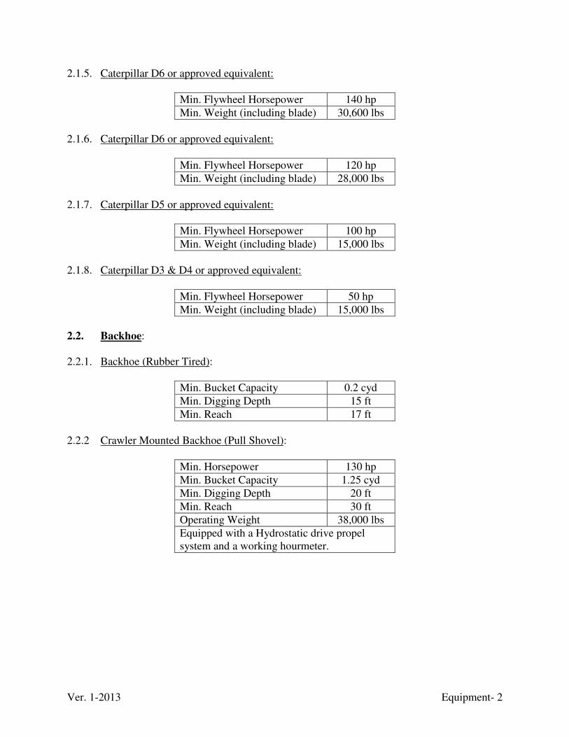
Ver. 1-2013 Equipment- 2
2.1.5. Caterpillar D6 or approved equivalent:
Min. Flywheel Horsepower 140 hp
Min. Weight (including blade) 30,600 lbs
2.1.6. Caterpillar D6 or approved equivalent:
Min. Flywheel Horsepower 120 hp
Min. Weight (including blade) 28,000 lbs
2.1.7. Caterpillar D5 or approved equivalent:
Min. Flywheel Horsepower 100 hp
Min. Weight (including blade) 15,000 lbs
2.1.8. Caterpillar D3 & D4 or approved equivalent:
Min. Flywheel Horsepower 50 hp
Min. Weight (including blade) 15,000 lbs
2.2. Backhoe: 2.2.1. Backhoe (Rubber Tired):
Min. Bucket Capacity 0.2 cyd
Min. Digging Depth 15 ft
Min. Reach 17 ft
2.2.2 Crawler Mounted Backhoe (Pull Shovel):
Min. Horsepower 130 hp
Min. Bucket Capacity 1.25 cyd
Min. Digging Depth 20 ft
Min. Reach 30 ft
Operating Weight 38,000 lbs
Equipped with a Hydrostatic drive propel system and a working hourmeter.
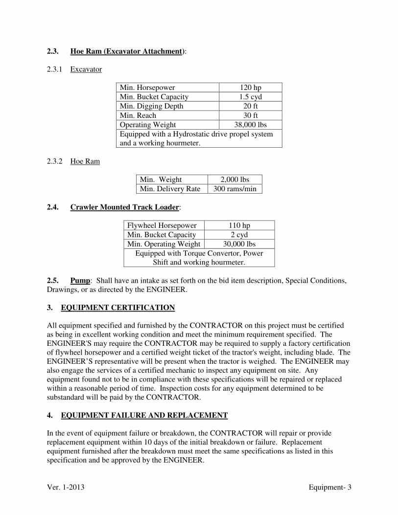
Ver. 1-2013 Equipment- 3
2.3. Hoe Ram (Excavator Attachment): 2.3.1 Excavator
Min. Horsepower 120 hp
Min. Bucket Capacity 1.5 cyd
Min. Digging Depth 20 ft
Min. Reach 30 ft
Operating Weight 38,000 lbs
Equipped with a Hydrostatic drive propel system and a working hourmeter.
2.3.2 Hoe Ram
Min. Weight 2,000 lbs
Min. Delivery Rate 300 rams/min
2.4. Crawler Mounted Track Loader:
Flywheel Horsepower 110 hp
Min. Bucket Capacity 2 cyd
Min. Operating Weight 30,000 lbs
Equipped with Torque Convertor, Power Shift and working hourmeter.
2.5. Pump: Shall have an intake as set forth on the bid item description, Special Conditions, Drawings, or as directed by the ENGINEER. 3. EQUIPMENT CERTIFICATION
All equipment specified and furnished by the CONTRACTOR on this project must be certified as being in excellent working condition and meet the minimum requirement specified. The ENGINEER'S may require the CONTRACTOR may be required to supply a factory certification of flywheel horsepower and a certified weight ticket of the tractor's weight, including blade. The ENGINEER’S representative will be present when the tractor is weighed. The ENGINEER may also engage the services of a certified mechanic to inspect any equipment on site. Any equipment found not to be in compliance with these specifications will be repaired or replaced within a reasonable period of time. Inspection costs for any equipment determined to be substandard will be paid by the CONTRACTOR. 4. EQUIPMENT FAILURE AND REPLACEMENT
In the event of equipment failure or breakdown, the CONTRACTOR will repair or provide replacement equipment within 10 days of the initial breakdown or failure. Replacement equipment furnished after the breakdown must meet the same specifications as listed in this specification and be approved by the ENGINEER.

Ver. 1-2013 Equipment- 4
Failure to repair and/or replace broken down equipment within 10 days will be considered as failure to perform. This declaration of failure to perform will result in an unsatisfactory Performance Evaluation and Receiving Report filed with the Finance and Administration Cabinet. 5. OPERATOR QUALIFICATIONS
All equipment operators shall be competent and experienced with the type of equipment for which they are assigned. Failure of any operator to display productivity commensurate to this requirement shall be grounds for the ENGINEER to require a replacement in that specific operating position. 6. SAFETY STANDARDS
All equipment used on this project must meet all of the appropriate federal and state safety requirements.
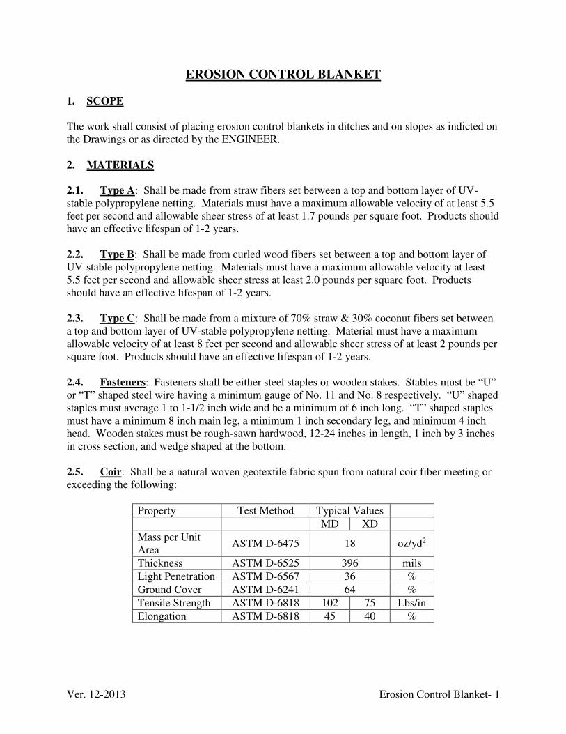
Ver. 12-2013 Erosion Control Blanket- 1
EROSION CONTROL BLANKET 1. SCOPE
The work shall consist of placing erosion control blankets in ditches and on slopes as indicted on the Drawings or as directed by the ENGINEER. 2. MATERIALS
2.1. Type A: Shall be made from straw fibers set between a top and bottom layer of UV-stable polypropylene netting. Materials must have a maximum allowable velocity of at least 5.5 feet per second and allowable sheer stress of at least 1.7 pounds per square foot. Products should have an effective lifespan of 1-2 years. 2.2. Type B: Shall be made from curled wood fibers set between a top and bottom layer of UV-stable polypropylene netting. Materials must have a maximum allowable velocity at least 5.5 feet per second and allowable sheer stress at least 2.0 pounds per square foot. Products should have an effective lifespan of 1-2 years. 2.3. Type C: Shall be made from a mixture of 70% straw & 30% coconut fibers set between a top and bottom layer of UV-stable polypropylene netting. Material must have a maximum allowable velocity of at least 8 feet per second and allowable sheer stress of at least 2 pounds per square foot. Products should have an effective lifespan of 1-2 years. 2.4. Fasteners: Fasteners shall be either steel staples or wooden stakes. Stables must be “U” or “T” shaped steel wire having a minimum gauge of No. 11 and No. 8 respectively. “U” shaped staples must average 1 to 1-1/2 inch wide and be a minimum of 6 inch long. “T” shaped staples must have a minimum 8 inch main leg, a minimum 1 inch secondary leg, and minimum 4 inch head. Wooden stakes must be rough-sawn hardwood, 12-24 inches in length, 1 inch by 3 inches in cross section, and wedge shaped at the bottom. 2.5. Coir: Shall be a natural woven geotextile fabric spun from natural coir fiber meeting or exceeding the following:
Property Test Method Typical Values
MD XD
Mass per Unit Area
ASTM D-6475 18 oz/yd2
Thickness ASTM D-6525 396 mils
Light Penetration ASTM D-6567 36 %
Ground Cover ASTM D-6241 64 %
Tensile Strength ASTM D-6818 102 75 Lbs/in
Elongation ASTM D-6818 45 40 %
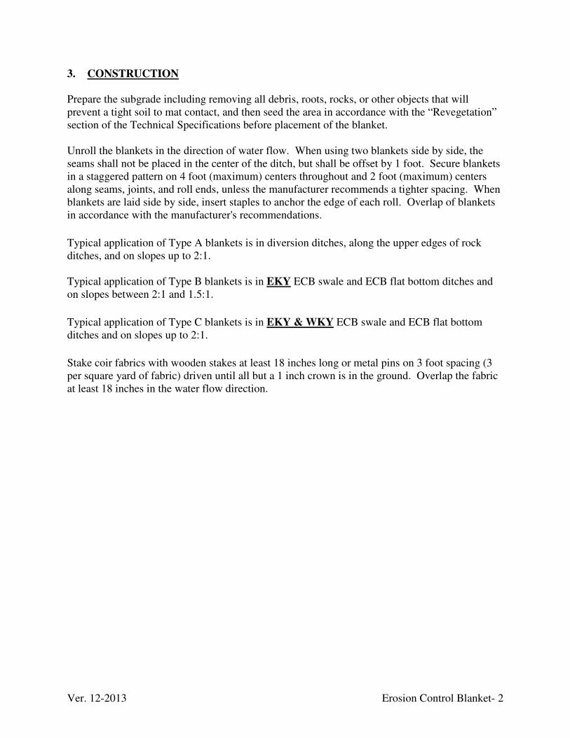
Ver. 12-2013 Erosion Control Blanket- 2
3. CONSTRUCTION
Prepare the subgrade including removing all debris, roots, rocks, or other objects that will prevent a tight soil to mat contact, and then seed the area in accordance with the “Revegetation” section of the Technical Specifications before placement of the blanket. Unroll the blankets in the direction of water flow. When using two blankets side by side, the seams shall not be placed in the center of the ditch, but shall be offset by 1 foot. Secure blankets in a staggered pattern on 4 foot (maximum) centers throughout and 2 foot (maximum) centers along seams, joints, and roll ends, unless the manufacturer recommends a tighter spacing. When blankets are laid side by side, insert staples to anchor the edge of each roll. Overlap of blankets in accordance with the manufacturer's recommendations.
Typical application of Type A blankets is in diversion ditches, along the upper edges of rock ditches, and on slopes up to 2:1. Typical application of Type B blankets is in EKY ECB swale and ECB flat bottom ditches and on slopes between 2:1 and 1.5:1.
Typical application of Type C blankets is in EKY & WKY ECB swale and ECB flat bottom ditches and on slopes up to 2:1.
Stake coir fabrics with wooden stakes at least 18 inches long or metal pins on 3 foot spacing (3 per square yard of fabric) driven until all but a 1 inch crown is in the ground. Overlap the fabric at least 18 inches in the water flow direction.
Ver. 1-2013 Fence- 1
FENCE 1. SCOPE
This work shall consist of furnishing and constructing fences of the height, type, and at the location specified on the Drawings or as directed by the ENGINEER. Fence shall involve the construction of fences as either safety fence, property fence or replacement fence. If an existing fence is encountered during construction that has not been identified on the drawings, DO NOT DISTURB THE FENCE, immediately notify the Resident Inspector and await further instructions from the ENGINEER.
1.1. Temporary Safety Fences: Shall be lightweight orange plastic barriers used to mark active construction boundaries, limit access, and restrict entry around open trenches, pits, holes, etc. These are incidental to the overall construction efforts. 1.2. Permanent Safety Fences: Shall be chain link fences placed to along the top/front of retaining walls, highwalls, and other various places that may cause a potential hazard to the public.
1.3. Other Fences: Shall be chain link, woven-wire or barb-wire fences that will be disturbed during construction. These fences may mark property lines. DAML will surveyed and reference these fences prior to their disturbance. Once construction is complete, DAML will relocation the fence position for the contractor to replace the fence. DAML will not state nor infer
reestablishment of said features to be the true property boundary corners and/or lines. See
“Structure Removal / Replacement” technical specification for further information
regarding property fences.
2. MATERIALS
2.1. Plastic Fence: The material shall be polypropylene standing 4 feet tall and a high visibility orange color. Follow manufacture recommendations for post, use minimum of 6 feet centers or less if manufacturer suggest or as required by ENGINEER.
2.2. Chain-Link Fabric: Use 0.148-inch nominal diameter wire woven in 2 inch mesh. Coat Type I fabric to conform to Class D. Furnish fabric for fences 5 feet high that has the top selvages knuckled and bottom selvages knuckled or twisted and barbed. Furnish fabric for fences 8 feet high or higher with both top and bottom selvages twisted and barbed. 2.3. Chain-Link Post Caps and Socket Type Brace Connections: Post, Rails, Gate Frames, and Expansion Sleeves. With zinc-coated steel fabric or with aluminum-coated steel fabric, use either zinc-coated steel or zinc-acrylic coated steel. With aluminum alloy fabric, use aluminum alloy. 2.4. Fabric Ties: Use either a minimum 0.148-inch nominal diameter aluminum alloy or 0.120-inch nominal diameter galvanized steel.
Ver. 1-2013 Fence- 2
2.5. Hog Rings and Tension Wire: With zinc-coated steel fabric or with aluminum-coated steel fabric use zinc-coated steel wire or aluminum-coated steel wire. Ensure that steel ties and wire conform to ASTM F 626, except that the minimum weight of coating is 0.6 ounces per square foot. With aluminum alloy fabric, use aluminum alloy wire. 2.6. Miscellaneous Fittings and Hardware: With zinc coated steel fabric or with aluminum-coated steel fabric use zinc-coated steel. With aluminum alloy fabric, use aluminum alloy. 2.7. Woven Wire Fabric: Use either zinc-coated steel or aluminum-coated steel. Provide the type and size and style specified in the Contract. Zinc-coated fabric shall conform to ASTM A 116 and aluminum-coated fabric to ASTM A 584. If barbed wire is used it shall be either zinc-coated steel , aluminum coated steel or aluminum alloy in accordance with KYTC Standard Specifications for Road and Bridge Construction. Use barbs of 4-point pattern spaced at intervals of 5 inches.
2.8. Posts and Braces: Posts and braces shall be either steel posts/braces conforming to ASTM F 1043 and ASTM F 1083 or treated wood posts/braces conforming to either AWPA C 5 or AWPA C 2.
2.9. Brace Wire: Shall conform to ASTM A 777-91 except provide a minimum weight coating of 0.6 ounce per square foot. Use size 0.148-inch nominal diameter or larger.
2.10. Woven-Wire Fabric Ties: Use either a minimum 0.109 nominal diameter galvanized steel conforming to ASTM F 626 except ensure that the minimum weight of coating is 0.6 ounce per square foot or 0.148-inch nominal diameter aluminum alloy.
2.11. Concrete: Shall be Class A concrete conforming to the “Concrete” technical specification. 3. CONSTRUCTION
Before starting fencing operations, remove all brush, stumps, logs, and debris that will interfere with the proper construction of the fence. Remove or trim sound standing trees in the fence line as directed. Construct fence with new materials according to the Standard Drawings and as specified in this section. Install fence as one of the first construction operations. Where tying fence to a new structure, erect a temporary fence until the structure is complete and the permanent fence can be anchored to the structure in the manner specified on the Drawings. Install fence facing the property owner except on horizontal curves. On horizontal curves, install the fence to pull against all posts. Apply sufficient tension between pull posts to make the fence stock tight. Install pull posts at all breaks in horizontal alignment of the fence, and at sharp breaks in vertical alignment. For tangents and curves up to one degree, space pull posts a maximum of 500 feet on centers; ensure that curves 1º - 4º have pull posts spaced a maximum of 250 feet on centers; and curves over 4º have pull posts installed each time the angle of deflection increases 5º.
Ver. 1-2013 Fence- 3
3.1. Setting Posts: Set all posts at the required depths and intervals as designated in the Drawings or AML Standard Details. Set posts plumb and in true alignment on the side where the wire is attached. Dig holes for posts to full depth and with sufficient diameter to allow placement of concrete. When encountering solid rock at grade or below, drill a hole one foot deep and slightly larger than the outside dimensions of the post or brace in the rock, and concrete in the post. At line posts where top of rock is 8 inches or less below grade, remove the anchor plate. Field cut posts and braces to fit maximum depth whenever encountering solid rock. Set all end, gate, corner, and pull posts, and anchor them in concrete placed to the top of the ground, finished smooth, and sloped to drain. Brace all end, gate, and corner posts. Brace pull posts in two directions. Brace corner posts in the direction of each line of the fence. Anchor the metal braces from the metal posts in concrete that is crowned at the top to shed water. Brace concrete posts with a pole or bar of the same type of material as the post. Loop galvanized smooth wire having a minimum diameter of 0.148 inch around the braced post near the ground, and then loop it around the line post at 12 inches below its top continuing between the posts until four strands of wire are in place and the ends of the wire are securely fastened together. Then twist the strands of wire together until the brace pole is in compression. Do not allow the compression to be great enough to cause lateral springing in the brace pole. Allow concrete anchors to cure for at least 5 days before erecting the fence. Where safety fences are called for on concrete walls, the posts shall be bolted to the wall.
Posts shall not be set on the top of the concrete walls.
3.2. Fencing: Tie any intersecting fence to an independent pull post. Stretch fence fabric taut and securely fasten it to each post. Accomplish stretching with a stretcher that will produce equal tension in each line wire. Stretch fabric until the tension is just below the point of producing displacement in the tension crimps. At each end, corner, or gate post, cut and turn each strand of line wire around the post and tie it back to itself with no less than three turns. When it is necessary to splice two sections of fence, make the splice by placing together the end stay wires of each section, and twist the end of each line wire around the stay wires and back onto itself with no less than three turns; or splice the fence by using ENGINEER approved splicing sleeves designed for that purpose. Attach the fence to each wood post with a staple for each line wire and as many additional staples as necessary to firmly secure the wire. Use tension wires and rails in erection of fences to stretch the fabric. When shown on the Standard Drawings, place, stretch taut, and secure at ends the top or bottom tension wires to all posts in a manner before placing fabric. When a top rail is required, secure the bar at each end before stretching and tying the fabric. Secure ends of the fabric with stretcher bars threaded through the loops of the fabric and secured to the posts by means of clamps with bolts and nuts. Use the number of clamps as indicated. Place the fabric by securing one end and applying sufficient tension to remove all slack before making attachments elsewhere. Fasten the fabric to the line posts and to the top tension wire or to the top rail, with tie wires or bands. Determine the number of tension bands required per post of fence by taking the height of the fence in feet and subtracting one. Space tie wires for attaching fence to the top tension wire or top rail on 24 inch centers. Space tie wires for attaching fence to intermediate or line posts on 14 inch centers. Space tie wires on chain link gates on 24 inch centers (when applicable). Install the chain link fence around utility installations facing the highway with the barbed wire arms at a 45º angle extending toward the highway. Design and install post caps for all tubular posts to exclude
Ver. 1-2013 Fence- 4
moisture from inside the posts, and install socket type brace end connections to exclude moisture from inside the rails. 3.3. Gates: Erect gates at locations specified in the Drawings or as directed by the ENGINEER. Erect the gate plumb with its hinges firmly attached to the post and to the gate. Allow the gate to swing freely when opened. Install the latch so it works easily and secures the gate when closed. 3.4. Finishing: Ensure that the tops of all posts are at a uniform height above the ground or at a uniform distance above the top of the chain-link fabric. Ensure that the finished fence is true to line, taut, and solid at all points. Dispose of all surplus excavated material and other debris resulting from construction and leave the fence line with a neat and orderly appearance.
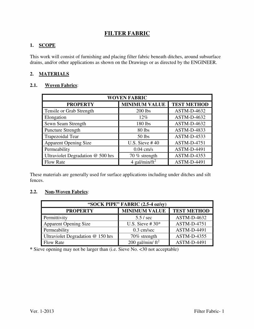
Ver. 1-2013 Filter Fabric- 1
FILTER FABRIC
1. SCOPE
This work will consist of furnishing and placing filter fabric beneath ditches, around subsurface drains, and/or other applications as shown on the Drawings or as directed by the ENGINEER. 2. MATERIALS
2.1. Woven Fabrics:
WOVEN FABRIC
PROPERTY MINIMUM VALUE TEST METHOD
Tensile or Grab Strength 200 lbs ASTM-D-4632
Elongation 12% ASTM-D-4632
Sewn Seam Strength 180 lbs ASTM-D-4632
Puncture Strength 80 lbs ASTM-D-4833
Trapezoidal Tear 50 lbs ASTM-D-4533
Apparent Opening Size U.S. Sieve # 40 ASTM-D-4751
Permeability 0.04 cm/s ASTM-D-4491
Ultraviolet Degradation @ 500 hrs 70 % strength ASTM-D-4353
Flow Rate 4 gal/min/ft2 ASTM-D-4491
These materials are generally used for surface applications including under ditches and silt fences. 2.2. Non-Woven Fabrics:
“SOCK PIPE” FABRIC (2.5-4 oz/sy)
PROPERTY MINIMUM VALUE TEST METHOD
Permittivity 5.5 / sec ASTM-D-4632
Apparent Opening Size U.S. Sieve # 30* ASTM-D-4751
Permeability 0.3 cm/sec ASTM-D-4491
Ultraviolet Degradation @ 150 hrs 70% strength ASTM-D-4355
Flow Rate 200 gal/min/ ft2 ASTM-D-4491
* Sieve opening may not be larger than (i.e. Sieve No. <30 not acceptable)
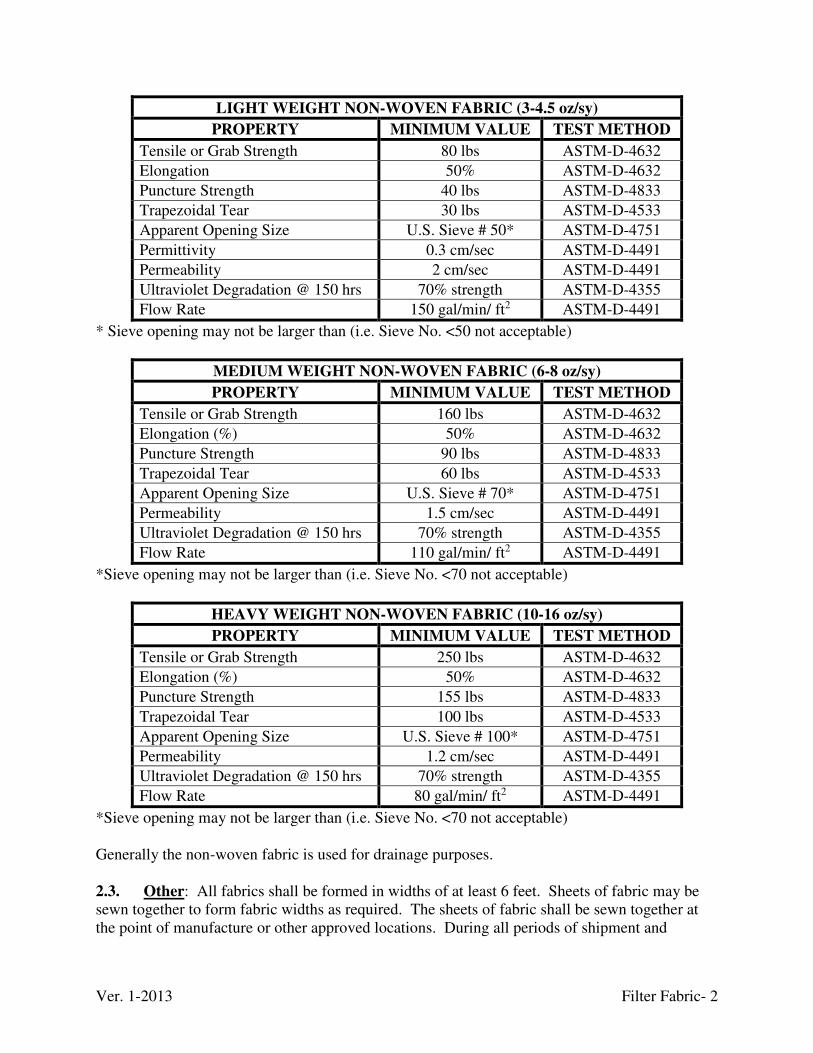
Ver. 1-2013 Filter Fabric- 2
LIGHT WEIGHT NON-WOVEN FABRIC (3-4.5 oz/sy)
PROPERTY MINIMUM VALUE TEST METHOD
Tensile or Grab Strength 80 lbs ASTM-D-4632
Elongation 50% ASTM-D-4632
Puncture Strength 40 lbs ASTM-D-4833
Trapezoidal Tear 30 lbs ASTM-D-4533
Apparent Opening Size U.S. Sieve # 50* ASTM-D-4751
Permittivity 0.3 cm/sec ASTM-D-4491
Permeability 2 cm/sec ASTM-D-4491
Ultraviolet Degradation @ 150 hrs 70% strength ASTM-D-4355
Flow Rate 150 gal/min/ ft2 ASTM-D-4491
* Sieve opening may not be larger than (i.e. Sieve No. <50 not acceptable)
MEDIUM WEIGHT NON-WOVEN FABRIC (6-8 oz/sy)
PROPERTY MINIMUM VALUE TEST METHOD
Tensile or Grab Strength 160 lbs ASTM-D-4632
Elongation (%) 50% ASTM-D-4632
Puncture Strength 90 lbs ASTM-D-4833
Trapezoidal Tear 60 lbs ASTM-D-4533
Apparent Opening Size U.S. Sieve # 70* ASTM-D-4751
Permeability 1.5 cm/sec ASTM-D-4491
Ultraviolet Degradation @ 150 hrs 70% strength ASTM-D-4355
Flow Rate 110 gal/min/ ft2 ASTM-D-4491
*Sieve opening may not be larger than (i.e. Sieve No. <70 not acceptable)
HEAVY WEIGHT NON-WOVEN FABRIC (10-16 oz/sy)
PROPERTY MINIMUM VALUE TEST METHOD
Tensile or Grab Strength 250 lbs ASTM-D-4632
Elongation (%) 50% ASTM-D-4632
Puncture Strength 155 lbs ASTM-D-4833
Trapezoidal Tear 100 lbs ASTM-D-4533
Apparent Opening Size U.S. Sieve # 100* ASTM-D-4751
Permeability 1.2 cm/sec ASTM-D-4491
Ultraviolet Degradation @ 150 hrs 70% strength ASTM-D-4355
Flow Rate 80 gal/min/ ft2 ASTM-D-4491
*Sieve opening may not be larger than (i.e. Sieve No. <70 not acceptable) Generally the non-woven fabric is used for drainage purposes. 2.3. Other: All fabrics shall be formed in widths of at least 6 feet. Sheets of fabric may be sewn together to form fabric widths as required. The sheets of fabric shall be sewn together at the point of manufacture or other approved locations. During all periods of shipment and
Ver. 1-2013 Filter Fabric- 3
storage, the fabric shall be wrapped in a heavy-duty covering to protect the fabric from direct sunlight, ultraviolet rays, temperatures greater than 140oF, mud, dirt, dust, and debris. Furnish a Certificate of Compliance from the manufacturer with each shipment of fabric to the Resident Inspector. The certificate shall be signed by an authorized official having legal authority to bind the company attesting that the fabric meets the specified chemical, physical, and manufacturing requirements. The certificate shall also include actual test results for each physical requirement of this specification. The ENGINEER may require a sample of 5 square yards with each shipment for verification testing at no cost to the COMMONWEALTH. 3. CONSTRUCTION
Prepare the surface to receive filter fabric by removing obstructions, debris, or sharp objects that may puncture the fabric. Place the fabric with the long dimension parallel to the flow line and lay it smooth and free of tension, stress, folds, wrinkles, or creases. Do not expose the fabric to sunlight for a period of greater than two weeks. If the fabric is damaged during construction, placing a piece of fabric that is large enough to cover the damaged area and meet the overlap requirement shall repair the torn or punctured section. 3.1. Laps: When more than one strip is necessary, overlap strips longitudinally a minimum of 24 inches and transversely a minimum of 18 inches with the upstream strip laid over the downstream strip. Install fastener pins through both strips of overlapped fabric at no less than 5 foot intervals along a line through the midpoint of the overlap, and at any other locations as necessary to prevent slippage of the fabric. 3.2. Channel Lining: Protect the fabric from damage due to the placement of the channel lining by limiting the height of drop of the material to no greater than 3 feet, or by placing a cushioning layer of sand on top of the fabric before dumping the material. Fabric shall not be placed until it can be covered avoiding damage from water, wind, and deterioration from undue exposure. The CONTRACTOR shall demonstrate that the placement technique will not damage the fabric. 3.3. Subsurface Drains: Place and shape the fabric to the sides and bottom of the trench without stretching the fabric. Protect the fabric from damage due to the placement of the crushed aggregate by limiting the height of drop of the material to no greater than 3 feet, or by placing a cushioning layer of sand on top of the fabric before dumping the material. Fabric shall not be placed until it can be covered avoiding damage from water, wind, and deterioration from undue exposure. The CONTRACTOR shall demonstrate that the placement technique will not damage the fabric. Fold the fabric over the backfilled trench and secure it with steel pins at intervals of 5 feet to produce a double thickness of fabric over the top of the trench, unless the fill aggregate is to be brought to the surface and left exposed.
Ver. 1-2013 Flume- 1
FLUME
1. SCOPE
The work covered by this specification shall include all labor, equipment, materials, and performing all operations necessary to provide and install a cutthroat flume in accordance with these Technical Specification and as indicated on the Drawings, Special Conditions, and as directed by the ENGINEER. 2. MATERIALS
2.1. Cutthroat flume: Flumes should be as manufactured by TRACOM, Inc., Alpharetta, Georgia or approved equivalent. The flume shall have a permanently attached high visibility staff gauge graduated in tenths and hundredths of a foot. Most applications will use 36 inch long x 8 inch wide sized for 39 - 2,712 gallons per minute discharge rate. 2.2. Timber: Use 6 x 6 inch and 4 x 4 inch pressure treated lumber in the flume approach and outlet sections. 2.3. Spikes: Spikes shall be 5/16 inch diameter galvanized steel nails. 2.4. Reinforcement Bars: Shall be 60 KSI, #5 rebar conforming to the “Steel” technical specification. 2.5. Concrete: Shall be Class A concrete conforming to the “Concrete” technical specification. 3. CONSTRUCTION
Compact the embankment in the area and construct the flume approach and outlet structure with timbers, spikes, and rebar as shown on the Drawings, outlined in the manufacture’s installation instructions, or as approved by the ENGINEER. Ensure that the flume is plumb and the bottom is level. Embed the flume in concrete or grout, or attach appropriate installation material to the anchor clips as recommended by the manufacturer or as directed by the ENGINEER. Hand compaction of the embankment material near the approach and outlet structure and the flume may be required as directed by the ENGINEER.
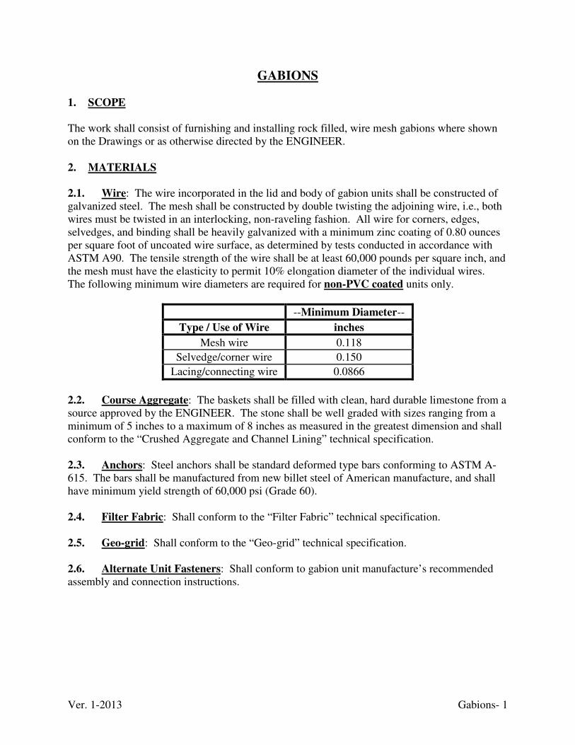
Ver. 1-2013 Gabions- 1
GABIONS
1. SCOPE
The work shall consist of furnishing and installing rock filled, wire mesh gabions where shown on the Drawings or as otherwise directed by the ENGINEER. 2. MATERIALS
2.1. Wire: The wire incorporated in the lid and body of gabion units shall be constructed of galvanized steel. The mesh shall be constructed by double twisting the adjoining wire, i.e., both wires must be twisted in an interlocking, non-raveling fashion. All wire for corners, edges, selvedges, and binding shall be heavily galvanized with a minimum zinc coating of 0.80 ounces per square foot of uncoated wire surface, as determined by tests conducted in accordance with ASTM A90. The tensile strength of the wire shall be at least 60,000 pounds per square inch, and the mesh must have the elasticity to permit 10% elongation diameter of the individual wires. The following minimum wire diameters are required for non-PVC coated units only.
--Minimum Diameter--
Type / Use of Wire inches
Mesh wire 0.118
Selvedge/corner wire 0.150
Lacing/connecting wire 0.0866
2.2. Course Aggregate: The baskets shall be filled with clean, hard durable limestone from a source approved by the ENGINEER. The stone shall be well graded with sizes ranging from a minimum of 5 inches to a maximum of 8 inches as measured in the greatest dimension and shall conform to the “Crushed Aggregate and Channel Lining” technical specification. 2.3. Anchors: Steel anchors shall be standard deformed type bars conforming to ASTM A-615. The bars shall be manufactured from new billet steel of American manufacture, and shall have minimum yield strength of 60,000 psi (Grade 60). 2.4. Filter Fabric: Shall conform to the “Filter Fabric” technical specification. 2.5. Geo-grid: Shall conform to the “Geo-grid” technical specification. 2.6. Alternate Unit Fasteners: Shall conform to gabion unit manufacture’s recommended assembly and connection instructions.
Ver. 1-2013 Gabions- 2
3. CONSTRUCTION
3.1 Fabrication
3.1.1. General: The gabion units shall be fabricated in such a manner that the base, sides, ends, and lids can be assembled at the construction site into a rectangular unit of the specified sizes and of a single woven mesh unit. The body of the units shall be of single unit construction. All perimeter edges of the mesh forming the unit shall be securely selvedged so that the joints formed by tying the selvedges have at least the same strength as the body of the mesh. Lacing wire shall be supplied in sufficient quantity to permit all sides, ends, and diaphragms of the body so that they are securely fastened. Tolerance limits for height, length, and width are ±3% of the manufacturer's stated sizes. Gabions shall be made in 3 feet cells (3’ H x 3’ W x 3’ L) unless otherwise approved by the
ENGINEER.
3.1.2. Gabions: The gabions shall be constructed with a hexagonal weave having an opening of approximately 3-1/4 inches by 4-1/2 inches. When the gabion length exceeds its width, it shall be supplied with diaphragms to form individual cells of equal length and width. The gabion unit shall be furnished with the necessary diaphragms secured in position on the base so that no additional tying will be necessary. The diaphragms shall be of the same material composition as the gabion. 3.1.3. Certification: Present a manufacturer certification to the Resident Inspector for each batch of gabions delivered to a job site stating that the material conforms to the requirements of this Specification. The certification shall be on the manufacturer's letterhead and shall be signed by an officer of that company. Any gabions that are suspect will be tested to determine if they meet the requirements of this Technical Specifications 3.2. Installation: Prepare the foundation as indicated on the Drawings. The ENGINEER will inspect and approve approved the foundation prior to gabion placement. Install filter fabric and/or geo-grid as directed on the Drawings, AML Standard Details, Special Conditions, and as directed by the Engineer. Assemble empty units individually on a hard, flat surface. Care must be exercised to assure that each basket is stretched or manipulated as necessary to achieve the proper rectangular shape. Connect all units to the adjoining units, while empty, by lacing wire along the perimeters of their contact surfaces. Use continuous stitching with alternating single and double loops at 4 inch intervals to secure diaphragms, ends and sides, the closure of units, and to connect adjoining units. Sides, ends, and diaphragms must be erected and laced to ensure the correct orientation of all seams and creases. Securely fasten all ends of lacing wire with no wire protruding. Once assembled, set empty units to the lines and grades shown on the Drawings, or as directed by the ENGINEER. Stretch empty units after lacing to obtain uniform alignment and to remove kinks. A standard fence stretcher, "come-along”, or other means of tensioning the unit may be used. Offset the seams of adjacent rows of gabion units (no substitution).
Ver. 1-2013 Gabions- 3
Carefully fill the baskets with stone by hand and/or machine to maintain alignment; to avoid bulges, damage to coating, and/or separation of units; and to minimize voids. The ENGINEER may require the CONTRACTOR to use hand labor to selectively place the layers of stone along exposed surfaces (i.e., top, front, and ends) to provide a uniform surface and an overall appearance suitable to the site-specific situation at each installation. The maximum height from which stone may be dropped into gabion units shall not exceed 36 inches. In gabions over 2 foot high, the stone is to be placed in 12 inch lifts; adjusted by hand, if necessary, to form a reasonable smooth surface, and cross-ties (or bracing wires) installed. Loop cross-ties through the mesh on opposing sides of the basket, and the wire tightened by twisting. 3.3. Alternatives: The ENGINEER may approve alternate’s to the lacing wire used to secure the shape of the gabion before placing and on horizontal surfaces where attached to each row of gabion. All vertical surfaces in retaining walls must be secured with the standard lacing
wire.
Ver. 1-2013 Gate Valves- 1
GATE VALVES 1. SCOPE
This work shall consist of furnishing all labor, equipment and materials, and performing all operations involved with the installation of the gate valves and valve enclosures as shown on the Drawings and as directed by the ENGINEER. 2. MATERIALS
2.1. Gate Valve: The valves shall be 6 x 10 inch non-rising stem polyvinyl chloride (PVC) gate valves with 2 inch square operating nuts. The valves shall be as manufactured by Asahi/America, Inc., or an approved equivalent. 2.2. Mechanical Joint Restraints (Flange Connection): All connections between pipe and flanges on gate valves shall be according to the manufacturer’s recommendations and approved by the ENGINEER. 2.3. Valve Stem Extension: Connect the valve operating nut to the valve stem with extensions that will allow valve operation from the surface. Provide the Division with a tool for operating the valve from outside the enclosure. The tool must be at least 1-1/2 inch diameter painted metal tube. 2.4. Valve Enclosure and Lid: The valve enclosure shall be cylindrical in shape with a minimum inside diameter necessary to accommodate the valve body, and installed to the depth and dimensions shown on the Drawings or as directed by the ENGINEER. The valve enclosure may be a commercial valve/meter box or a high density or corrugated polyethylene (HDPE) pipe. Valve enclosures shall have a removable locking lid as approved by the ENGINEER. 3. CONSTRUCTION
Install the gate valve, enclosures, and lids at the locations and to the elevations shown on the Drawings or as directed by the ENGINEER plumb, and according to the manufacturer’s recommendations. Brace or laterally support stem extensions and connect to the valve operating nuts according to the manufacturer’s recommendation. Stem extensions shall extend to the finished grade surface and shall accommodate hand tool T-bars necessary for operations from the surface. Exercise extreme care during backfill and compaction operations, to prevent any damage or undue stress to the valves, flanges, or enclosures.
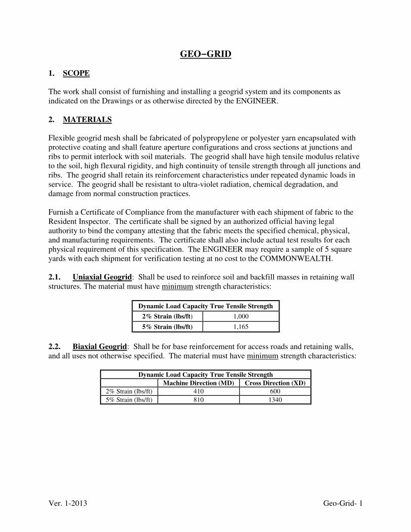
Ver. 1-2013 Geo-Grid- 1
GEO-GRID 1. SCOPE
The work shall consist of furnishing and installing a geogrid system and its components as indicated on the Drawings or as otherwise directed by the ENGINEER. 2. MATERIALS
Flexible geogrid mesh shall be fabricated of polypropylene or polyester yarn encapsulated with protective coating and shall feature aperture configurations and cross sections at junctions and ribs to permit interlock with soil materials. The geogrid shall have high tensile modulus relative to the soil, high flexural rigidity, and high continuity of tensile strength through all junctions and ribs. The geogrid shall retain its reinforcement characteristics under repeated dynamic loads in service. The geogrid shall be resistant to ultra-violet radiation, chemical degradation, and damage from normal construction practices. Furnish a Certificate of Compliance from the manufacturer with each shipment of fabric to the Resident Inspector. The certificate shall be signed by an authorized official having legal authority to bind the company attesting that the fabric meets the specified chemical, physical, and manufacturing requirements. The certificate shall also include actual test results for each physical requirement of this specification. The ENGINEER may require a sample of 5 square yards with each shipment for verification testing at no cost to the COMMONWEALTH. 2.1. Uniaxial Geogrid: Shall be used to reinforce soil and backfill masses in retaining wall structures. The material must have minimum strength characteristics:
Dynamic Load Capacity True Tensile Strength
2% Strain (lbs/ft) 1,000
5% Strain (lbs/ft) 1,165
2.2. Biaxial Geogrid: Shall be for base reinforcement for access roads and retaining walls, and all uses not otherwise specified. The material must have minimum strength characteristics:
Dynamic Load Capacity True Tensile Strength
Machine Direction (MD) Cross Direction (XD)
2% Strain (lbs/ft) 410 600
5% Strain (lbs/ft) 810 1340
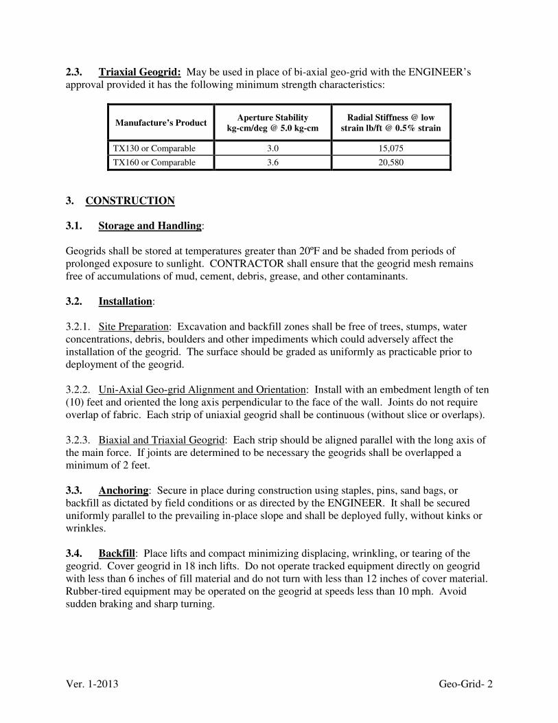
Ver. 1-2013 Geo-Grid- 2
2.3. Triaxial Geogrid: May be used in place of bi-axial geo-grid with the ENGINEER’s approval provided it has the following minimum strength characteristics:
Manufacture’s Product Aperture Stability
kg-cm/deg @ 5.0 kg-cm
Radial Stiffness @ low
strain lb/ft @ 0.5% strain
TX130 or Comparable 3.0 15,075
TX160 or Comparable 3.6 20,580
3. CONSTRUCTION
3.1. Storage and Handling: Geogrids shall be stored at temperatures greater than 20ºF and be shaded from periods of prolonged exposure to sunlight. CONTRACTOR shall ensure that the geogrid mesh remains free of accumulations of mud, cement, debris, grease, and other contaminants. 3.2. Installation: 3.2.1. Site Preparation: Excavation and backfill zones shall be free of trees, stumps, water concentrations, debris, boulders and other impediments which could adversely affect the installation of the geogrid. The surface should be graded as uniformly as practicable prior to deployment of the geogrid. 3.2.2. Uni-Axial Geo-grid Alignment and Orientation: Install with an embedment length of ten (10) feet and oriented the long axis perpendicular to the face of the wall. Joints do not require overlap of fabric. Each strip of uniaxial geogrid shall be continuous (without slice or overlaps). 3.2.3. Biaxial and Triaxial Geogrid: Each strip should be aligned parallel with the long axis of the main force. If joints are determined to be necessary the geogrids shall be overlapped a minimum of 2 feet. 3.3. Anchoring: Secure in place during construction using staples, pins, sand bags, or backfill as dictated by field conditions or as directed by the ENGINEER. It shall be secured uniformly parallel to the prevailing in-place slope and shall be deployed fully, without kinks or wrinkles. 3.4. Backfill: Place lifts and compact minimizing displacing, wrinkling, or tearing of the geogrid. Cover geogrid in 18 inch lifts. Do not operate tracked equipment directly on geogrid with less than 6 inches of fill material and do not turn with less than 12 inches of cover material. Rubber-tired equipment may be operated on the geogrid at speeds less than 10 mph. Avoid sudden braking and sharp turning.
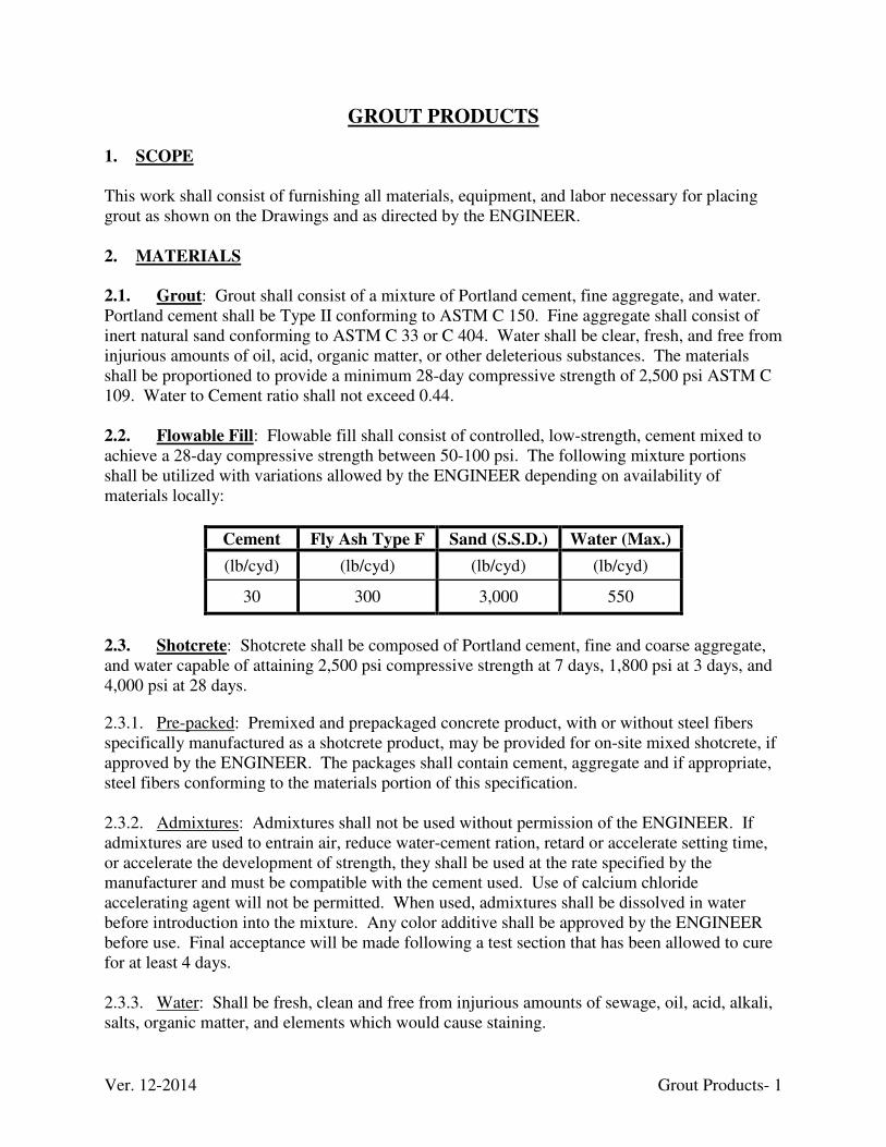
Ver. 12-2014 Grout Products- 1
GROUT PRODUCTS
1. SCOPE
This work shall consist of furnishing all materials, equipment, and labor necessary for placing grout as shown on the Drawings and as directed by the ENGINEER. 2. MATERIALS
2.1. Grout: Grout shall consist of a mixture of Portland cement, fine aggregate, and water. Portland cement shall be Type II conforming to ASTM C 150. Fine aggregate shall consist of inert natural sand conforming to ASTM C 33 or C 404. Water shall be clear, fresh, and free from injurious amounts of oil, acid, organic matter, or other deleterious substances. The materials shall be proportioned to provide a minimum 28-day compressive strength of 2,500 psi ASTM C 109. Water to Cement ratio shall not exceed 0.44. 2.2. Flowable Fill: Flowable fill shall consist of controlled, low-strength, cement mixed to achieve a 28-day compressive strength between 50-100 psi. The following mixture portions shall be utilized with variations allowed by the ENGINEER depending on availability of materials locally:
Cement Fly Ash Type F Sand (S.S.D.) Water (Max.)
(lb/cyd) (lb/cyd) (lb/cyd) (lb/cyd)
30 300 3,000 550
2.3. Shotcrete: Shotcrete shall be composed of Portland cement, fine and coarse aggregate, and water capable of attaining 2,500 psi compressive strength at 7 days, 1,800 psi at 3 days, and 4,000 psi at 28 days.
2.3.1. Pre-packed: Premixed and prepackaged concrete product, with or without steel fibers specifically manufactured as a shotcrete product, may be provided for on-site mixed shotcrete, if approved by the ENGINEER. The packages shall contain cement, aggregate and if appropriate, steel fibers conforming to the materials portion of this specification.
2.3.2. Admixtures: Admixtures shall not be used without permission of the ENGINEER. If admixtures are used to entrain air, reduce water-cement ration, retard or accelerate setting time, or accelerate the development of strength, they shall be used at the rate specified by the manufacturer and must be compatible with the cement used. Use of calcium chloride accelerating agent will not be permitted. When used, admixtures shall be dissolved in water before introduction into the mixture. Any color additive shall be approved by the ENGINEER before use. Final acceptance will be made following a test section that has been allowed to cure for at least 4 days. 2.3.3. Water: Shall be fresh, clean and free from injurious amounts of sewage, oil, acid, alkali, salts, organic matter, and elements which would cause staining.
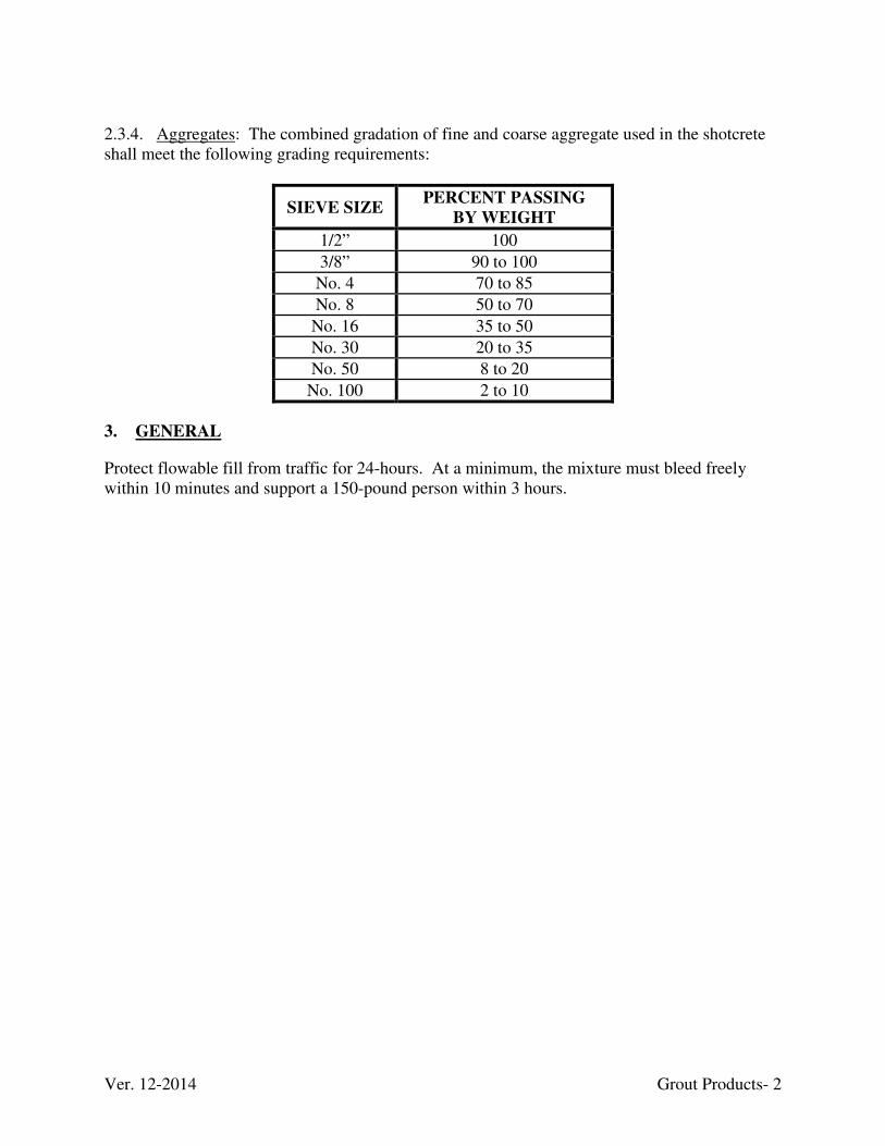
Ver. 12-2014 Grout Products- 2
2.3.4. Aggregates: The combined gradation of fine and coarse aggregate used in the shotcrete shall meet the following grading requirements:
SIEVE SIZE PERCENT PASSING
BY WEIGHT
1/2” 100
3/8” 90 to 100
No. 4 70 to 85
No. 8 50 to 70
No. 16 35 to 50
No. 30 20 to 35
No. 50 8 to 20
No. 100 2 to 10
3. GENERAL
Protect flowable fill from traffic for 24-hours. At a minimum, the mixture must bleed freely within 10 minutes and support a 150-pound person within 3 hours.
Ver. 1-2013 Guardrails- 1
GUARDRAILS
1. SCOPE
This work shall consist of furnishing all materials, equipment, and labor necessary for placing guardrails as shown on the Drawings and as directed by the ENGINEER. 2. MATERIALS
2.1. Guardrails: Shall be steel “W” beam material meeting the requirements of AASHTO M180 “Standard Specifications for Corrugated Sheet Steel Beam for Highway Guardrail, Type 2 Class A” and the KY Transportation Cabinet’s “Standard Specifications for Road and Bridge Construction”, current edition. 2.2. Guardrail End Treatment: Shall be steel “W” beam material meeting the requirements of AASHTO M180 “Standard Specifications for Corrugated Sheet Steel Beam for Highway Guardrail, Type 2 Class A” and the KY Transportation Cabinet’s “Standard Specifications for Road and Bridge Construction”, current edition.
2.3. Wooden Post: Shall be the KY Transportation Cabinet’s “Standard Specifications for Road and Bridge Construction”, current edition. 2.4. Steel Post: Shall be the KY Transportation Cabinet’s “Standard Specifications for Road and Bridge Construction”, current edition.
Ver. 1-2013 Hazardous Material- 1
HAZARDOUS MATERIAL 1. SCOPE
The work shall consist of the proper disposal and documentation of all hazardous material remains located within the construction limits. 2. MATERIALS
Disposal of hazardous materials includes oil, fuel, batteries, lubricants, and chemical treatment (previously used for water treatment) located within the construction limits. 3. GENERAL
All hazardous materials located within the construction limits shall be marked or flagged by the ENGINEER. It is recommended that the CONTRACTOR walk the sites and determine the risk. Those materials, which have a salvage value, may be disposed of in a manner as approved by the ENGINEER. The remains shall be transported in a safe manner, being covered or otherwise secured as necessary to prevent loss in transit.
Ver. 1-2013 Highwall- Slope Rockfall Barrier Fence- 1
HIGHWALL- SLOPE ROCKFALL BARRIER FENCE
1. SCOPE
The work shall consist of providing safeguards and protection to the residents, private property, and public infrastructure from rocks, boulders, mud, debris, trees or other materials that are excavated or dislodged during the construction project. 2. MATERIALS
The rock fall barrier shall be an AXI-050 barrier manufactured by Geobrugg North America, LLC or an approved equivalent. 2.1. Ring Nets: The nets shall be made from interlocking steel rings, each ring with a maximum nominal diameter of 11.81 inches. Rings shall be composed of steel wire coiled into a loop with seven loops per ring. Three steel clips shall be fastened around each ring to hold the ring together. Each ring shall connect to the four adjoining rings by passing through them. The wire shall be high tensile strength carbon steel wire with a nominal 0.118 inches diameter and the minimum breaking strength of the wire shall be 256,000 pounds/square inch. The wire shall be coated with super coating and the minimum weight of the coating shall be 0.41 ounces/square foot. 2.2. Wire Mesh: Nets shall be covered with chain link mesh, which shall be attached to the wire rope netting and fastened with galvanized hog rings and/or galvanized tie wire on 2 foot centers horizontally and vertically. Chain link material shall be 2 inch, 9-gauge minimum conforming to AASHTO M181-90, shall be zinc coated in accordance with A392-84, Class 1 Standards, and may be PVC coated for color. 2.3 Net Support Posts & Ground Plates: Shall be hot dipped galvanized steel meet the requirements for ASTM A36 of sizes and shapes defined on the Drawings, manufacturer recommendations, or as directed by the ENGINEER. Posts shall be fabricated with ground plate designed for rock or loose soil/concrete foundation depending on site conditions. Use breakaway plates to attach post the ground plates. 2.4. Net Support Ropes: The system shall have double top and double bottom support ropes and shall be manufactured from 3/4 inch diameter, galvanized, 6x19 construction or equivalent IWRC wire rope. Install a brake rope at the end of each support rope run using GS-8001 brake rings or equivalent. 2.5. Lateral Anchor Ropes: Lateral anchor ropes shall incorporate a factory swedged eye on one end and shall be manufactured from 3/4 inch diameter, galvanized, 6x19 construction or equivalent IWRC wire rope.
Ver. 1-2013 Highwall- Slope Rockfall Barrier Fence- 2
2.6. Lateral Anchors: The anchors shall be wire rope anchors made from 3/4 inch diameter, galvanized, 6x19 construction or equivalent IWRC wire rope and shall incorporate a factory swedged eye on one end. The anchor pullout strength shall be 58,540 pounds and must be verified by the contractor in the field. The testing shall consist of a pullout test incorporating 20% of the total number of anchors. If more than 25% of the tested anchors fail, all anchors shall be tested. Failed anchors shall be replaced by the contractor at no additional cost to the owner. Testing shall be performed using a temporary yoke or load frame. No part of the yoke or load frame shall bear within 3 feet of the anchor. 2.7. Vertical End Ropes: The ropes shall be made from 3/4 inch diameter, galvanized, 6x19 construction or equivalent IWRC wire rope and shall incorporate a factory swedged eye on each end. 2.8. Shackles: Shackles shall be used to fasten the ring nets to each other and to the support ropes. Along the top and bottom of each net, 1/2 inch shackles shall be used. Along the sides of each net, 7/16 inch shackles shall be used. 2.9. Miscellaneous Materials: All miscellaneous hardware such as wire rope clips, thimbles, bolts, etc. shall be supplied by the manufacturer with the system.
2.10. Wire Rope Specifications: All wire rope for the support ropes, lateral anchor ropes, vertical end ropes, run top ropes and wire rope anchors shall meet the Federal Specification RR-W-410D or ASTM A1023/1023M or equivalent. 2.11. Corrosion Protection: The ropes for the support ropes, lateral anchor ropes, vertical end ropes, run top ropes and wire rope anchors shall meet Federal Specification RR-W-410D or ASTM A1023/A1023M for galvanizing. Hog rings or tie wire shall be supplied with zinc coating meeting the requirements of ASTM A641-92. 2.12. Other: The rockfall barrier system shall be manufactured and assembled in accordance with the contract documents and plans, and the manufacturer’s standards and requirements as follows:
a) Provide a rockfall control fence system with a minimum height of at least fourteen 14.70 feet and of sufficient structural capacity to absorb impact design loads of 184 foot-tons of kinetic energy without the passage of particles larger than 30 inches in diameter through the barrier and with little or no maintenance required after multiple rock impacts. No tie-back (retaining) ropes for the posts will be allowed in the design.
b) Supply at the time of proposal submission a certification that the barrier to be supplied
has received a Swiss Federal Research Institute (WSL) or European ETAG 27 Category A test report and certificate (or equal) for that specific system design being provided on the contract demonstrating the barrier equals or exceeds the stated performance in a
Ver. 1-2013 Highwall- Slope Rockfall Barrier Fence- 3
vertical drop test. A proposal received without the system’s certified test report and ETA certification will be rejected.
c) Select a manufacturer engaged in designing and manufacturing rockfall protection
systems, having a minimum of 5 years of documented experience manufacturing of such systems used in a similar application and capacity. Supply written evidence from manufacturer demonstrating certification of a quality assurance program, as well as proof and validity of seller’s liability insurance.
3. CONSTRUCTION
3.1. Excavation and Foundations: Perform the excavation of the foundation for the columns and rock and soil anchors in accordance with the typical cross sections shown on the Drawings. The distance from centerline to centerline of the columns must be kept as close as possible to that shown on the Drawings. The spacing cannot exceed ±3 inches of the distance as indicated on the design drawings. Prior to placing of concrete, moisten the earth subgrade to a minimum depth of 2 inches from the soil and concrete surfaces. All loose soil or rocks shall be removed from the holes. The minimum concrete strength is to be 4,000 psi. After the concrete placement in the forms maintain the concrete at a minimum temperature of 50º F for a period of 72 hours. 3.2. Rockfall System Installation: The rockfall system shall be installed in accordance with the AXI-050 Product Manual. 3.3. Field Installation Supervision: The manufacturer shall include one, 8 hour day of installation supervision by a qualified Field Engineer in order to ensure the system is properly installed. Travel and living expenses shall be borne by the manufacturer. The cost for the installation supervision shall be included in the cost for the system. 3.4. Shipping and Labeling of Materials: All material shall be properly labeled by the manufacturer in order for the CONTRACTOR to identify the system components easily with the manufacturer’s design drawings to minimize installation time. All materials shall be shipped by the manufacturer to the job site via common carrier. The cost for shipping shall be included in the cost for the system. 3.5. Drawings: Submit the manufacturer’s generic layout and design drawings to the ENGINEER for comments and/or approval. Fabrication of the system shall commence only after the manufacturer has received drawing approval from the customer. The cost for the manufacturer’s assistance and drawings shall be incidental. 3.6. Rock Fall Pad: The rock fall pad will be a temporary energy absorption system to prevent falling rocks from damaging the rock fall barrier and public property. Construct the pad to conform to the dimensions of the plans and details. It can be constructed from shale talus or

Ver. 1-2013 Highwall- Slope Rockfall Barrier Fence- 4
soil excavated within the project limits or from sand or gravel imported from a quarry. There will be no additional payment for materials used, neither imported nor excavated. The rock fall pad can be built in segments in the precise area of excavation or it can be built in its entirety.
Ver. 1-2013 Highwall- Slope Rockfall Netting Light Duty- 1
HIGHWALL- SLOPE ROCKFALL NETTING LIGHT DUTY
1. SCOPE
This shall include all highwall preparation efforts and securely installing rockfall netting on all designated areas as depicted on the Drawings and as directed by the ENGINEER. In addition, it shall include installing anchor bars with grout to fasten the rockfall netting to highwall as directed by the ENGINEER. It shall be flexible zinc coated rockfall netting of the type and sizes specified below. It is made of wire mesh of the type and size and selvedges as specified in the following paragraphs.
2. MATERIAL
2.1. Wire: All wire used in the fabrication of the rockfall netting and in the wiring operations during construction for the zinc coating and tensile strength shall be in accordance with the requirements of ASTM A- 641-92, Standard Specification for Zinc-Coated (Galvanized) Carbon Steel Wire for galvanized wire, Class 3, and soft temper as measured before fabrication of the netting. The nominal diameter of the wire used in the fabrication of the netting shall be 0.120 inches mesh, 0.85 oz/sq. ft. Standard Zinc-Coated rockfall netting shall have a nominal length of 150 feet and nominal width of 12 feet. Other dimensions may be used as approved by the ENGINEER. 2.2. Zinc: All wire used in the fabrication of the rockfall netting and in the wiring operations during construction shall be coated to ASTM A-641-92 for zinc coated (galvanized) carbon steel wire. The adhesion of the zinc coating to the wire shall be such that, when wrapped around a mandrel in accordance with ASTM A-641-92, the zinc coating will not crack or flake to such an extent that any zinc can be removed by rubbing with the bare fingers.
2.3. Lacing Wire: Lacing and connecting wire shall be supplied with the rockfall netting for all wiring operations carried out in the construction of the meshwork. The lacing wire procedure consists of cutting a length of lacing wire approximately 1-1/2 times the distance to be laced (not to exceed 5 feet). Securing one of the wires at the corner by looping and twisting, alternately lacing with single and double loops every other mesh opening at intervals of not more than 6 inches and securing the other end of the wire to selvedges by looping and twisting. The nominal diameter of lacing wire shall be 0.0866 inches and 0.70 oz/sq. ft. 2.4. Fasteners: Rings can be used in lieu of lacing wire for assembly and installation operations of the mesh. Rings shall be supplied with the same zinc coating as the mesh and the wire diameter of the rings conforming to the “Gabion” technical specification. Spacing of the fasteners must not exceed 6 inches.
2.5. Selvedges: All edges of the standard rockfall netting including end-panels and the diaphragms, if any, shall be mechanically selvedged in such a way as to prevent unraveling of
Ver. 1-2013 Highwall- Slope Rockfall Netting Light Duty- 2
the mesh and to develop the full strength of the mesh. The wire used for the selvedge shall have a diameter greater than that of the wire used to form the mesh, namely: For the 8 x 10 type mesh made of wire having a nominal diameter of 0.120 inches the selvedge shall be of wire having a nominal diameter of 0.1535 inches or greater and 0.90 oz. /sq. ft. coating weight. 2.6. Anchor bars: Unless shown otherwise on the Drawings, anchor bars shall consist of No. 5 reinforcement bar bent into an L-shape. The short leg of the L-shaped bar shall be approximately 6 inches long and the long leg 2 feet long.
2.7. Shotcrete: Shall conform to the “Grout Products” technical specification.
2.8. Tolerances: Tolerances on the diameter of all wire in the above clauses shall be permitted in accordance with ASTM A-641-92. Tolerances of ± 5% on the width, and length of the rockfall netting shall be permitted. All dimensions are subject to confirmation as manufacturing requirements may dictate that the nominal sizes shall be varied from those given herein and tolerance shall apply to these adjusted dimensions. Test shall be made on the wire before fabrication of the rockfall netting on a sample 12 inches long. Elongation shall not be less than 12%, in accordance with the requirements of ASTM A-370-92, Standard Test Methods and Definitions for Mechanical Testing of Steel Products.
3. CONSTRUCTION
3.1. Fabrication: The mesh shall be hexagonal woven mesh with the joints formed by twisting each pair of wires through three half turns. The size of the mesh conforms to the specifications issued by the plant and shall be of 8 x 10 type mesh. Nominal mesh size is 3-1/4 to 4-1/2 inches. Incorporate diaphragms to form cells having a length not greater than one and half the width of the mesh. 3.2. Highwall Preparation: Thoroughly clean the highwall remove all loose rock, soil and debris prior to the installation of rockfall netting by pressure washing or other methods approved by the ENGINEER. A hoe ram shall be utilized as well to remove the existing overhang and other protruding/large unstable rock as directed by the ENGINEER. The hoe ram shall have a minimum weight of 2,000 lbs. and a minimum delivery capability of 300 rams per minute. Exercise extreme caution with working around highwall area as loose rock and debris exists within this area. Prevent workers from entering areas where potentially loose rock and other debris may fall thereby eliminating potential hazards to workers. Protect existing structures during all phases of work. 3.3. Rockfall Netting Installation: Once highwall has thoroughly cleaned and secured, set No. 5 anchor bars into pre-drilled holes 24 inch (min.) within the highwall and grouted in place.
Ver. 1-2013 Highwall- Slope Rockfall Netting Light Duty- 3
Secure the rockfall netting to the anchor bars using lacing wire or other techniques approved by the ENGINEER. The ENGINEER reserves the right to request the CONTRACTOR to place the anchor bars more frequently than depicted in the drawings if in the opinion of the ENGINEER it is warranted for long term structural integrity. Shape the rockfall netting to contour the highwall (2 inch max. off highwall face) with weep holes installed (8 inch PVC pipe) sloped to drain outward. No shotcrete shall be applied to the rockfall netting until approval is given from the ENGINEER.
3.4. Anchor bars: Unless otherwise shown on the Drawings, place anchor bars at approximately 8 foot maximum centers with the beginning row near the top of highwall, both horizontal and vertical, in 1-1/4 inch holes drilled into the rock/soil face twenty inches deep. Blow clear the drilled hole prior to installation of the anchor bar. Completely fill the drilled hole with neat cement grout using a grout tube extending to the bottom of the hole. Push the anchor bar into the grout-filled hole and center such that the short leg of the L-shaped shaped bar points upward and is located about 1-1/2 inches from the rock/soil surface. Other locations and more frequent spacing may be required when the opinion of the ENGINEER, significant attachment is being achieved.
Ver. 1-2013 Highwall-Slope Rockfall Netting Heavy Duty- 1
HIGHWALL-SLOPE ROCKFALL NETTING HEAVY DUTY 1. SCOPE
The work consists of furnishing, transporting and constructing a slope protection system in accordance with the Drawings, manufacturer’s instructions and guidelines, and as directed by the ENGINEER. The intent is to stabilize a large section of exposed rock slope of an almost vertical highwall created by pre-law mining practices.
The system shall be designed to withstand static and dynamic forces generated from rocks sliding under the permanently installed system and have a proven satisfactory performance record. The ENGINEER must pre-approve any systems. 2. MATERIALS
The manufacturer shall be regularly engaged in the manufacturing of rockfall protection systems, having documented experience with manufacturing of rockfall protection systems used in a similar application and capacity. The manufacturer shall supply written evidence demonstrating certification of a quality assurance program, as well as proof and validity of seller’s liability insurance. 2.1. Netting: The rockfall netting shall be S4 SPIDER® Slope Drape manufactured by GEOBRUGG® or an approved equivalent. The netting shall be woven construction and shall be diamond shaped with an inner-circle opening of 9.1 inches. The netting shall be made with 4-millimeter diameter wire in a 1 x 3 strand construction with the ends of each wire formed into a loop and twisted. The loops of the wire netting shall be fastened together to prevent unraveling of the net. The wire shall be alloyed high strength carbon steel wire with a minimum tensile strength of 256 KSI. The mesh shall have a minimal load capacity tensile strength of 15.1 kips/ft. The wire shall be galvanized with a zinc/aluminum coating with a minimum weight of 0.0256 pounds per square foot. The coating shall be 95% zinc and 5% aluminum. The size of the net opening shall be 11.5 inches by 19.7 inches (+ 2%) and the twisted strand diameter will be 0.339 inches. The net shall have 1.04 meshes per foot going across the net and 0.61 meshes per foot going down the net. Rolls shall measure 11.5 feet wide by 65.5 feet in length (753 sq. ft.). 2.2. No.9 Gauge Wire Fencing Mesh and Hog Rings: The No.9-Gauge, 2 x 2 inch, galvanized chain link wire mesh fencing placed underneath the SPIDER® Mesh or an approved equivalent shall be attached by means of 9-gauge galvanized hog rings on 2 foot centers. 9-gauge wire fencing mesh shall conform to AASHTO M181-90, shall be zinc coated in accordance with A392-84, Class 1 Standards, and may be PVC coated for color. 2.3. Net Support Ropes: Support ropes shall have a diameter of 3/4 inch and shall be of 6x19 construction or equivalent IWRC with a minimum breaking strength of 52,920 lbs.
Ver. 1-2013 Highwall-Slope Rockfall Netting Heavy Duty- 2
2.4. Rock and Soil Anchors: Wire rope anchors shall be constructed from 3/4 inch wire rope of 6x19 or equivalent IWRC with a minimum breaking strength of 52,920 lbs and be 10 feet long. Each anchor shall have minimum pullout strength of 6 tons and must be verified by the Contractor in the field. The testing shall consist of a pullout test incorporating 20% of the total number of anchors. If more than 25% of the tested anchors fail, all anchors shall be tested. Failed anchors shall be replaced at no additional cost to the ENGINEER. Testing shall be performed against a temporary yoke or load frame. No part of the yoke or load frame shall bear within 3 feet of the anchor.
Anchors shall consist of 132 pounds per yard steel rail measuring 8 feet in length. All rail used for anchors shall be in good condition and free of defects, and shall be painted with two coats of rust protection paint 2.5. Miscellaneous Materials: All miscellaneous hardware such as 3/4 inch wire rope clips and 3/4 inch thimbles shall be galvanized. 2.6. Shackles: Three-eighth (3/8) inch galv. SPA shackles are used to fasten the net panels to each other. Three-fourth (3/4) inch shackles are used to fasten the support rope to the netting. 2.7. Wire Rope Specifications: All wire rope for the support ropes, seam ropes, and wire rope anchors shall meet the Federal Specifications RR-W-410D or equivalent. 2.8. Corrosion Protection: All wire ropes shall meet Federal Specification RR-W-410D for wire rope. All miscellaneous material associated with the rockfall system such as wire rope clips, bolts, nuts, and thimbles shall be hot dipped galvanized 3. CONSTRUCTION
3.1. Highwall Preparation: Thoroughly clean the highwall remove all loose rock, soil and debris prior to the installation of rockfall netting by pressure washing or other methods approved by the ENGINEER. A hoe ram shall be utilized as well to remove the existing overhang and other protruding/large unstable rock as directed by the ENGINEER. The hoe ram shall have a minimum weight of 2,000 lbs. and a minimum delivery capability of 300 rams per minute. Exercise extreme caution with working around highwall area as loose rock and debris exists within this area. Prevent workers from entering areas where potentially loose rock and other debris may fall thereby eliminating potential hazards to workers. Protect existing structures during all phases of work. 3.2. Rockfall Netting: Panels of the mesh will be secured together with 3/8 inch shackles to form one large drape mesh. Nine-gauge, 2 x 2 inch galvanized chain link will be secured to the mesh using 9-gauge galvanized hog rings to prevent smaller rock from passing through the larger mesh. A length of 3/4 inch wire rope will be woven into the mesh’s upper length to serve as a top support rope.
Ver. 1-2013 Highwall-Slope Rockfall Netting Heavy Duty- 3
Submit an anchoring layout plan to the ENGINEER for approval prior to installation. The anchor cables will be attached to the anchors and will run down to the support cable located immediately above the highwall. The anchor cables will be attached to the support cable in such a manner as to prevent slippage. The support cable will be located approximately 5 feet above the top of the highwall. The wire mesh sheets will then be draped over the supporting cable and secured. Each wire mesh panel will overlap the next by at least 2 feet. See the plan details for the anticipated general layout of anchors and cables. Secure wire rope anchors 3/4 inch diameter by 10 feet long equidistant in a line approximately 40 feet above the position where the drape’s top support rope is desired to be located. Secure wire rope anchors to highwall by drilling 2-1/2 inch diameter hole drilled minimum 4 foot into rock and grouted into place. Connect sets of 3/4 inch offset ropes with thimbles and wire rope clips on each end will then connect the mesh’s top support rope with the wire rope anchors via 3/4 inch shackles. 3.3. Field Installation Supervision: The manufacturer shall also include one 8 hour day for installation supervision by a qualified Field Engineer in order to ensure the system is properly installed. Travel and living expenses shall be borne by the manufacturer. The cost for the installation supervision shall be included in the cost for the system.
Ver. 1-2013 Industrial Mining Debris Removal- 1
INDUSTRIAL MINING DEBRIS REMOVAL
1. SCOPE
The work shall consist of the demolition, removal, and proper disposal of all mining equipment, abandoned utilities, foundations, structural materials and domestic debris remains located within all construction limits. 2. MATERIALS
Industrial mining debris consists of any heavy equipment (bulldozers, trucks), pipes, steel beams, large cables, tanks, trusses, metal roofing, and other items commonly associated with industrialize mining operations. This definition also includes abandoned utility poles, exposed concrete foundations and passenger vehicles located within all construction limits. All rights to property and existing materials within the project area will remain the property of the owner. Salvageable material rejected by the owner shall become the responsibility of the CONTRACTOR to dispose of in a proper manner subject to the approval of the ENGINEER. All non-salvageable or rejected structural elements, abandoned equipment and debris shall be transported to nearby project areas already requiring earthwork and buried as directed by the ENGINEER. Disturbances associated with demolition activities are to be graded and otherwise cleaned-up to the satisfaction of the ENGINEER, and then revegetated in accordance with the “Revegetation” technical specification. 3. CONSTRUCTION
Generally the work shall consist of the demolition and removal of all mining equipment, abandoned utilities, foundations, metal roofs and domestic debris from the project area and its transportation to, and appropriate placement, in a permitted landfill. The CONTRACTOR shall advise the ENGINEER of the landfill to be used or salvage intent and shall obtain the ENGINEER'S approval prior to the hauling of all remains. The remains shall be transported in a safe manner, being covered or otherwise secured as necessary to prevent loss in transit. The CONTRACTOR shall provide for safe conduct of the work, removal and disposition of materials, and protection of property, which is to remain undisturbed. The CONTRACTOR shall construct and maintain shoring, bracing, and supports as required. The CONTRACTOR shall insure that structural elements are not overloaded, and shall be responsible for increasing structural supports by adding new supports as may be required as a result of any cutting or removal of other elements. The CONTRACTOR shall take all necessary precautions to insure against damage to adjoining structure(s), which are to remain in place. Foundations of demolished structure(s) shall be removed to a minimum of 2 feet below the finished ground lines.
Ver. 10-2015 Mobilization/Demobilization- 1
MOBILIZATION / DEMOBILIZATION
1. SCOPE
This element of work shall consist of the mobilization of the CONTRACTOR'S forces and equipment necessary for performing the work required under the contract documents including the transportation of personnel, equipment, and operating supplies to the site; establishment of offices, buildings, and other necessary facilities at the site; and other preparatory work at the site. The work shall also include final cleanup of the work area and the demobilization of the CONTRACTOR’S forces and equipment. 2. MOBILIZATION 2.1. General: Mobilization shall be paid as a lump sum as shown on the Bid Schedule. 2.2. Payment: Reimbursement for "Mobilization" shall be divided into two incremental payments per project approximately equal to 75% and 25% respectively, of the approximate
percentage value of work to be done at each project or site based on the Summary of
Quantities breakdown. The first payment shall be made only after sufficient personnel, materials, equipment, and facilities have been mobilized to each particular project/site to demonstrate the CONTRACTOR'S intent to undertake the bulk of the work AND all utility companies have
been notified and the utilities marked in the field. The second payment shall be made after an amount of work equal to 10% of the total for remaining bid items as based on percentage value for each project/ and only after an acceptable schedule has been received for each site. Payment will not be made under this item for the purchase costs of materials having a residual value, the purchase costs of materials to be incorporated in the project, or the purchase costs of operating supplies. 2.3. Adjustments: This specification covers mobilization for work required by the contract at the time of award. If additional mobilization costs are incurred during performance of the Contract as a result of changed or added items of work for which the CONTRACTOR is entitled to an adjustment in contract price, compensation for such costs shall be included in the price adjustment for the items of work changed or added. 3. DEMOBILIZATION
3.1. General: Perform all work and operations necessary to accomplish final clean up including the removal of personnel, equipment, supplies, and incidentals from the project site.
Ver. 10-2015 Mobilization/Demobilization- 2
3.2. Final Cleanup: The COMMONWEALTH will not consider the work complete and will
not make final payment until all areas the CONTRACTOR occupied in connection with the reclamation work have been cleaned and vegetated or permanently stabilized. This includes but not limited to removal of all rubbish, equipment, excess materials, temporary structures, weeds and all other items deemed unacceptable by the ENGINEER. All rubbish and waste materials shall be removed from the construction area and disposed in a manner consistent with all applicable state and federal laws. All property, both public and private, that was damaged in the prosecution of the work shall be restored in an acceptable manner, restore positive drainage where practical, and leave all space under structures unobstructed and in such condition that drift will not collect and induce scouring or clogging. 3.3. Payment: When listed as a payment item, demobilization shall be paid as a lump sum as shown on the Bid Schedule. Payment will be until the final cleanup and demobilization are completed to the satisfaction of the ENGINEER. Demobilization will not be paid when the
project is not completed within the allowed contract period.
Failure to install and maintain sediment control throughout the project will result in the
forfeiture of demobilization. Failure to remove silt control fence (geotextile fabrics) shall
result in forfeiture of demobilization.
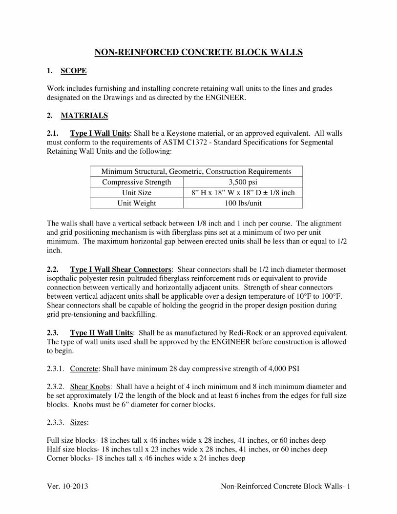
Ver. 10-2013 Non-Reinforced Concrete Block Walls- 1
NON-REINFORCED CONCRETE BLOCK WALLS
1. SCOPE
Work includes furnishing and installing concrete retaining wall units to the lines and grades designated on the Drawings and as directed by the ENGINEER. 2. MATERIALS
2.1. Type I Wall Units: Shall be a Keystone material, or an approved equivalent. All walls must conform to the requirements of ASTM C1372 - Standard Specifications for Segmental Retaining Wall Units and the following:
Minimum Structural, Geometric, Construction Requirements
Compressive Strength 3,500 psi
Unit Size 8” H x 18” W x 18” D ± 1/8 inch
Unit Weight 100 lbs/unit
The walls shall have a vertical setback between 1/8 inch and 1 inch per course. The alignment and grid positioning mechanism is with fiberglass pins set at a minimum of two per unit minimum. The maximum horizontal gap between erected units shall be less than or equal to 1/2 inch.
2.2. Type I Wall Shear Connectors: Shear connectors shall be 1/2 inch diameter thermoset isopthalic polyester resin-pultruded fiberglass reinforcement rods or equivalent to provide connection between vertically and horizontally adjacent units. Strength of shear connectors between vertical adjacent units shall be applicable over a design temperature of 10°F to 100°F. Shear connectors shall be capable of holding the geogrid in the proper design position during grid pre-tensioning and backfilling.
2.3. Type II Wall Units: Shall be as manufactured by Redi-Rock or an approved equivalent. The type of wall units used shall be approved by the ENGINEER before construction is allowed to begin. 2.3.1. Concrete: Shall have minimum 28 day compressive strength of 4,000 PSI 2.3.2. Shear Knobs: Shall have a height of 4 inch minimum and 8 inch minimum diameter and be set approximately 1/2 the length of the block and at least 6 inches from the edges for full size blocks. Knobs must be 6” diameter for corner blocks. 2.3.3. Sizes: Full size blocks- 18 inches tall x 46 inches wide x 28 inches, 41 inches, or 60 inches deep Half size blocks- 18 inches tall x 23 inches wide x 28 inches, 41 inches, or 60 inches deep Corner blocks- 18 inches tall x 46 inches wide x 24 inches deep
Ver. 10-2013 Non-Reinforced Concrete Block Walls- 2
2.4. Aggregate Backfill: Shall conform to the “Crushed Aggregate and Channel Lining” technical specification. 2.5. Pipes: Shall conform to the “Pipe” technical specification. 2.6. Concrete: Shall be Class “AA” concrete conforming to the “Concrete” technical specification. 2.7. Steel Reinforcement: Shall be 60 KSI steel conforming to the “Steel” technical specification. 2.8. Geo-grid: Shall be a bi-axial product conforming to the “Geo-grid” technical specification. 3. CONSTRUCTION
Check the materials upon delivery to assure proper material has been received and shall protect the materials from damage. Damaged material shall not be incorporated in the project. Prevent excessive mud, wet cement, and like materials from coming in contact with the units. Excavate to the lines and grades shown on the Drawings. Construct the reinforced concrete footer on undisturbed soil unless the ENGINEER requires a geo-grid and crushed aggregate pad prior to concrete placement. The pad must cure for a minimum of 7 days before placing any block on the footer. For steps and pavers, a minimum of one to 1-1/2 inches of free draining sand shall be screed smooth to act as a placement bed for the steps or pavers. All walls should terminate into the existing ground either due to winged ends or 90° corners.
3.1. Type I Wall Unit Installation:
3.1.1. Blocks: Place the first course of units on the footer at the appropriate line and grade. Check the alignment and level in all directions and insure that all units are in full contact with the base and properly seated. Place the front of units side-by-side. Do not leave gaps between adjacent units. Layout of corners and curves shall be in accordance with the manufacturer's recommendations. Install shear/connecting devices per manufacturer's recommendations. Place and compact drainage fill within and behind wall units. Place and compact backfill soil behind drainage fill. Follow wall erection and drainage fill closely with structure backfill. Maximum stacked vertical height of wall units, prior to unit drainage fill and backfill placement and compaction, shall not exceed two courses.
3.1.2. Structural Geo-grid Installation: Orient uni-axial geo-grid shall be oriented with the highest strength axis perpendicular to the wall alignment. Place the geo-grid horizontally on compacted backfill and attach to the modular wall units. Insert fiberglass rods into the blocks. Place the next course of modular concrete units over the geo-grid. Pull the geo-grid taut and anchor prior to backfill placement on the geo-grid. Geo-grid reinforcements shall be continuous
Ver. 10-2013 Non-Reinforced Concrete Block Walls- 3
throughout their embedment lengths and placed side-by-side to provide 100% coverage at each level. Spliced connections between shorter pieces of geo-grid or gaps between adjacent pieces of geo-grid are not permitted.
3.1.3. Reinforced Backfill Placement: Place, spread, and compact reinforced backfill in in lifts not to exceed 6 inches where hand compaction is used or 8-10 inches where heavy compaction equipment is used. Compact reinforced backfill to 95% proctor. The moisture content of the backfill material prior to and during compaction shall be uniformly distributed throughout each layer. Only lightweight hand-operated equipment shall be allowed within 3 feet from the tail of the modular concrete unit. Tracked construction equipment shall not be operated directly upon the geogrid reinforcement. A minimum fill thickness of 6 inches is required prior to operation of tracked vehicles over the geogrid. Tracked vehicle turning should be kept to a minimum to prevent tracks from displacing the fill and damaging the geogrid. Rubber tired equipment may pass over geogrid reinforcement at slow speeds, less than 10 mph. Sudden braking and sharp turning shall be avoided. At the end of each day's operation, slope the last lift of reinforced backfill away from the wall units to direct runoff away from wall face. Do not allow surface runoff from adjacent areas to enter the wall construction site.
3.1.4. Cap Installation: Glue cap units to underlying units with an all-weather adhesive recommended by the manufacturer.
3.2. Type II Wall Unit Installation
3.2.1. Blocks: Place the first course of units on the footer at the appropriate line and grade. Check the alignment and level in all directions and insure that all units are in full contact with the base and properly seated. Place the front of units side-by-side. Do not leave gaps between adjacent units. Layout of corners and curves shall be in accordance with the manufacturer's recommendations. Install shear/connecting devices per manufacturer's recommendations. Place and compact drainage fill within and behind wall units. Place and compact backfill soil behind drainage fill. Follow wall erection and drainage fill closely with structure backfill. Maximum stacked vertical height of wall units, prior to unit drainage fill and backfill placement and compaction, shall not exceed two courses.
Grind smooth any rough edges on the back of the concrete blocks prior to placement to avoid damage to the geogrid under tension.
3.2.2. Structural Geo-grid Installation: For any 21 inch block wall with heights greater than 15 feet or any 21 inch block wall regardless of wall height that will have constant additional surcharge loadings applied behind it, the contractor will be required to install geo-grid and make proper connection to the retaining wall blocks for reinforced soil walls. For 41 inch or 60 inch block walls, geo-grid may not be needed. Always check final plan design for these types of walls to see if geo-grid will be used. Place the bi-axial geo-grid perpendicular to the wall. Place the next course of modular concrete units over the geo-grid. Pull the geo-grid taut and anchor prior to backfill placement on the geo-grid. Geo-grid reinforcements shall be continuous throughout their embedment lengths and placed side-by-side to provide 100% coverage at each level. Spliced connections between shorter pieces of geo-grid or gaps between adjacent pieces of geo-

Ver. 10-2013 Non-Reinforced Concrete Block Walls- 4
grid are not permitted.
Geo-grid placement on corners shall follow the procedures outlined in the Design Manual for Segmental Retaining Walls, Second Edition, Copyright 1997, National Concrete Masonry Association, Herndon, VA. See the following details or convex and concave curve corners.
3.2.3. Reinforced Backfill Placement: Place, spread, and compact reinforced backfill in in lifts not to exceed 6 inches where hand compaction is used or 8-10 inches where heavy compaction equipment is used. Compact reinforced backfill to 95% proctor. The moisture content of the backfill material prior to and during compaction shall be uniformly distributed throughout each layer. Only lightweight hand-operated equipment shall be allowed within 3 feet from the tail of the modular concrete unit. Tracked construction equipment shall not be operated directly upon the geo-grid reinforcement. A minimum fill thickness of 6 inches is required prior to operation of tracked vehicles over the geo-grid. Tracked vehicle turning should be kept to a minimum to prevent tracks from displacing the fill and damaging the geo-grid. At the end of each day's operation, slope the last lift of reinforced backfill away from the wall units to direct runoff away from wall face. Do not allow surface runoff from adjacent areas to enter the wall construction site.
Ver. 12-2014 Pile & Lagging Retaining Wall- 1
PILE AND LAGGING RETAINING WALL 1. SCOPE
This work shall consist of furnishing all materials, equipment, and labor necessary for installing Pile and Lagging Retaining Wall as shown on the Drawings or as directed by the ENGINEER. Efforts include drilling, installation of steel piles, and placement of concrete lagging, filter fabric, subdrain, and stone backfill. 2. MATERIALS
2.1. Steel Piles: Shall conform to the “Steel” technical specification. 2.2. Steel Reinforcement: Shall conform to the “Steel” technical specification. 2.3. Concrete: Shall be Class AA concrete conforming to the “Concrete” technical specification. 2.4. Pre-cast Concrete Lagging: Precast concrete lagging shall be Class AA concrete conform to requirement of the “Concrete” technical specification. 2.5. Filter Fabric: Shall conform to the “Filter Fabric” technical specification. 2.6. Drain Pipe: Shall conform to the “Pipe” technical specification. 2.7. Aggregate Backfill: Shall conform to the “Crushed Aggregate and Channel Lining” technical specification. 3. CONSTRUCTION
3.1. Preparation Drilling & Excavation: Drill pilot holes to identify the depth to rock and report the result to the ENGINEER prior to ordering the steel piles. Excavate material and move to an approved waste area. 3.2. Piles: Drill each hole sufficiently large enough to accommodate the steel pile, reinforcing cage (if required), and concrete with 2” clearance between each component and the outer edge of the hole. The piles are to be set 10’ into competent rock (+2’ tolerance). The piles are to be concreted completely from the bottom of the hole to within 2 feet of the existing ground line, or as directed by the ENGINEER. Pump holes free of water and brace the steel piles
prior to placement of concrete. Pump the concrete through a hollow pipe beginning at the bottom of the drilled hole. Place concrete in such a manner that it does not strike any obstruction, such as the reinforcing steel or sides of the drill hole to avoid segregation of concrete. As concrete is injected, raise the hollow pipe with care to ensure that its tip remains approximately 2 feet below the surface of the concrete until the concrete reaches a point 3-5 feet below the surface.
Ver. 12-2014 Pile & Lagging Retaining Wall- 2
Complete all concrete placement operations for holes drilled during the working day. Level the tops of the piles by removing excess material above the final wall height. This cut off may be included in the ENGINEER’S installed and approved linear feet measurement. 3.3. Casing: Permanent or temporary casing of holes shall be used as required by the ENGINEER to maintain an open clean hole through the soil overburden and to prevent holes
with unstable sides from squeezing. Temporary casing or non-cased holes may be allowed provided an open clean hole of a required diameter through the soil overburden can be maintained. 3.4. Tolerances: Locate as shown on the Drawings or as directed by the ENGINEER. Install pile centers within ± 2 inches of the plan locations. Should the elevation of the bottom of the pre-drilled hole vary from the plan elevation more than ± 1 foot, the ENGINEER must approve the installation of the pile and injection of concrete prior to placement. Use a plumb bob, carpenter level, or other acceptable methods to verify acceptable alignment for the ENGINEER. The maximum permissible deviation for the exposed section of piles from vertical alignment shall be based on aesthetical and structural aspects. Maintain and provide records to the ENGINEER showing the depth to which each pile is placed, the deviation from vertical plumb, the amount of materials used, and any unusual conditions encountered during the installation. 3.5. Lagging: Install lagging between adjacent piles such that each lagging member extends to within one inch of the pile web. Final grading at the front of the wall shall not proceed until lagging placement is complete. 3.6. Filter Fabric: Place the filter fabric as shown on the Drawings. 3.7. Retaining Wall Subdrain: Install the drain as shown on the AML Standard Details. 3.8. Backfill: Place aggregate backfill behind the wall to the lines and grades shown on the Drawings. If filter fabric is used, limit the drop of rock backfill to no more than 3 feet. Backfill operations shall not commence until all lagging and filter fabric have been placed, and not until a test cylinder of the concrete has been successfully broken at 4,000 psi. 3.9. Final Grading: The rock backfill when indicated on the Drawings shall be covered with filter fabric and a layer of soil shall be placed over the exposed surface behind the wall if required by the Drawings. In all cases, at least a 5 feet strip of rock must be left exposed behind the wall. Areas adjacent to the wall shall be shaped and finished to blend with the surroundings as directed by the ENGINEER.
Ver. 12-2014 Pipe- 1
PIPE
1. SCOPE
This work shall consist of furnishing and installing drainage pipe at the locations shown on the drawings or as directed by the Engineer, including all necessary fittings and backfilling. 2. MATERIALS
2.1. Corrugated Metal Pipe (CMP): All corrugated metal pipe shall conform to the requirements of AASHTO M 36. Pipe shall have welded seams with helical corrugations having a pitch of two and 2-2/3 inches and a depth of 1/2 inch. The minimum metal thickness of the pipes shall be 14-gauge for 24 inch diameter or less and 12-gauge for 36 inch and greater diameter, unless fill heights dictate a different gauge according to the AML Standard
Details pipe fill charts. 2.2. CMP Connections: The connections between sections of pipe and end treatments shall be made with coupling bands or other mechanisms of durability equal to or greater than the pipe. Coupling bands shall meet the requirements of AASHTO M-36. 2.3. CMP Coatings: Any damage to the coating shall be repaired by thoroughly wire brushing the damaged area, removing all loose and cracked coating, removing all dirt and greasy material with solvent, and painting with two coats of material. If the coating is damaged in any individual area larger than 12 square inches, or if more than 0.2% of the total surface area of a length of pipe is damaged, the length will be rejected. 2.3.1. Zinc Coating: The repair coating shall be a zinc dust-zinc oxide primer or equivalent as specified by the manufacturer. 2.3.2. Bituminous Coatings: All BCCMP pipe shall be fully bituminous coated in accordance with AASHTO M-190. Breaks and scuffs in bituminous coatings that are less than 36 square inches in area shall be repaired by the application of two coats of hot asphaltic paint or a coating of cold applied bituminous mastic. The repair coating shall be at least 0.05 inches thick after hardening and bonded securely and permanently to the pipe. Whenever individual breaks exceed 36 square inches of area or when the total area of breaks exceed 0.5% of the total surface area of the pipe, whichever is less, the pipe will be rejected. 2.4. Reinforced Concrete Pipe (RCP): The drainage pipe shall be Class III RCP unless fill
heights dictate a different class according to the AML Standard Details pipe fill charts. The pipe can be circular or non-circular and the length as indicated on the Drawings or as directed by the ENGINEER. RCP WILL BE USED UNDER ALL PAVED ROADS WITH
FLOWABLE FILL.
2.5. High Density Polyethylene Pipe (HDPE): The drainage pipe shall be made of virgin high density polyethylene compounds which conform to the requirements of Type III, Category 4, 5, Grade P30, or P34 Class C per ASTM D-128. HDPE and pipe shapes shall meet the
Ver. 12-2014 Pipe- 2
requirements of ASTM F405, ASTM F667 AASHTO M-294-851; ASTM D-2122 with minimum 20 foot lengths. All HDPE pipe will be dual wall pipe meaning a corrugated exterior and smooth interior unless approved in writing otherwise by the ENGINEER. 2.6. Reinforced High Density Polyethylene Pipe (RHDPE): Shall be made from virgin high density polyethylene compounds and ribbing reinforcement manufactured using a high quality stress-rated thermoplastic meeting the requirements of ASTM F2562 “Standard Specification for Steel Reinforced Thermoplastic Ribbed Pipe and Fittings for Non-Pressure Drainage and Sewerage” or AASHTO Designation MP-20, Bridge Construction Section 26 & Design Section 12. 2.7. Dual Wall Polypropylene (DWPP): Shall be made from virgin impact modified copolymer polypropylene conforming to the requirements of ASTM D4101 “Standard Specification for Polypropylene Injection and Extrusion Materials.” Pipe shall have a smooth interior and annular exterior corrugations meeting or exceeding ASTM F2736, F2881, and AASHTO M330, for the respective diameters. 2.8. Triple Wall Polypropylene (TWPP): Shall be made from virgin impact modified copolymer polypropylene conforming to the requirements of ASTM D4101 “Standard Specification for Polypropylene Injection and Extrusion Materials.” Pipe shall have smooth interior and exterior surfaces with annular inner corrugations and meet ASTM F2764 and shall have minimum pipe stiffness of 46 psi when testing in accordance with ASTM D2412. 2.9. HDPE, RHDPE, DWPP, & HP Connections: Corrugated fittings may be either molded or fabricated by the manufacturer. The use of fittings supplied by the manufactures other than the supplier of the pipe shall not be permitted without the approval of the ENGINEER. Couplings shall be corrugated to match the pipe corrugations and the width shall not be less than half the nominal diameter of the pipe, split couplings shall be manufactured to engage an equal number of corrugations on each side of the pipe joint. Where required by the ENGINEER, a mastic type gasket or other gasket acceptable to the ENGINEER may be used. 2.10. Polyvinyl Chloride (PVC) Pipe: PVC pipe and fittings shall be Schedule 40 meeting the requirements of ASTM D-1785. The PVC pipe shall be delivered to the job site and handled by means, which provide adequate support to the pipe and do not subject it to undue stresses or damage. When handling and placing the PVC pipe, care shall be taken to prevent impact blows, abrasion damage, and gouging or cutting (by metal surfaces or rocks). All special handling requirements of the manufacturer shall be strictly observed. Special care shall be taken to avoid impact when the pipe must be handled at temperatures of 40°F or less.
Ver. 12-2014 Pipe- 3
The PVC pipe shall be stored on a relatively flat surface so that the barrels are evenly supported. Unless the pipe is specially manufactured to withstand exposure to ultraviolet radiation, it shall be covered with an opaque material when stored outdoors for a period of fifteen days or longer. All fittings and appurtenances for the PVC pipe shall be manufactured and furnished by the pipe supplier and have bell and spigot configurations compatible with that of the pipe. All solvent cement joints for PVC pipe and fittings shall be made in accordance with ASTM D-2855 for PVC pipe and fittings. All connections between the pipe and flanges on valves shall be according to the manufacturer’s recommendations and approved by the ENGINEER. 2.11. Aggregate Backfill: Shall conform to the “Crushed Aggregate and Channel Lining” technical specification. 2.12. Flowable Fill Backfill: Shall conform to the “Grout Products” technical specification. 2.13. Steel Plates: Shall conform to the “Steel Plates’ technical specification. 3. CONSTRUCTION
Exercise care in all operations, such as placing the pipe, jointing, bedding and backfilling. It shall be the CONTRACTOR'S responsibility to see that pipes are not damaged during unloading or placement, during compaction of the backfill by movement of excessively heavy equipment over the backfill, or by any other forces that may cause damage. Excavate trenches for pipes to the lines and grades shown on the Drawings. The trench shall be dry and unfrozen at the time the pipe is installed. Make soft and/or hard spots as uniform as practical with sand, gravel, crushed stone, or other suitable material to ensure even settlement of the pipe. Lay the outside laps of circumferential joints point upstream, with no longitudinal joints in the lower quadrant. Place backfill in layers not exceeding 6 inches loose thickness for hand operated machine compactors and 8 inches loose thickness for other compaction methods, unless otherwise specified. Fill material shall be free from organic material, stumps, large rocks, hard lumps, or clods larger than 3 inches in diameter. Sod, cinders, and frozen fill will not be allowed. Hand tampers for compacting horizontal layers should weigh not less than 20 pounds and have a maximum face of 6 x 6 inches. Sheepsfoot and rubber-tired tamping rollers can be used to compact backfill around the pipe provided they will not cause damage to the pipe. Power tampers and rollers must not contact the pipe. Fill adjacent to the pipe must be
hand or mechanically tamped. Bring the backfill up evenly on both sides of pipe for the full length of the pipe. Backfill the remainder of the trench with crushed aggregate. Use special materials for roadways as designated on the Drawings or provided in writing by the ENGINEER. Remove and relay pipe that is not in true alignment or which shows abnormal settlement after placement. Anchor pipes (especially HDPE & RHDPE pipe) before using flowable fill, in accordance
with these Technical Specifications. Failure to properly anchor pipes where they are in not

Ver. 12-2014 Pipe- 4
proper alignment or grade in accordance with the Drawings shall result in the
CONTRACTOR removing the pipe and relaying the pipe to the proper alignment and
grade.
All pipe placed without the use of a headwall or any type of anchor shall be flush with the
slope, where the water flowing out of the pipe will not create a condition that will cause the
pipe to be undercut.
Complete the installation of the pipe (including excavation, backfill, and temporary traffic base) in one day and coordinated beforehand with local residents. The CONTRACTOR must supply metal sheeting to allow access. All necessary arrangements are the responsibility of the CONTRACTOR, subject to the ENGINEER'S approval. The Drawings may specify that the
construction not interrupt the flow of traffic. In that case the ENGINEER must pre-
approve a traffic flow plan prior roadway disturbance.
Ver. 1-2013 Pneumatic Backstowing- 1
PNEUMATIC BACKSTOWING 1. SCOPE
The work shall consist of filling openings and voids with select graded aggregates utilizing a pneumatic backstowing process only. 2. MATERIALS
2.1. Granular Fill: Granular fill shall be size No. 57 or No. 8 coarse aggregate and conform to the “Crushed Aggregate and Channel Lining” technical specification. 3. CONSTRUCTION
Remove debris, rubble, and other loose material from the areas to be backfilled. Backfill the area using pneumatically stowed material in locations shown on the Drawings and as directed by the ENGINEER.
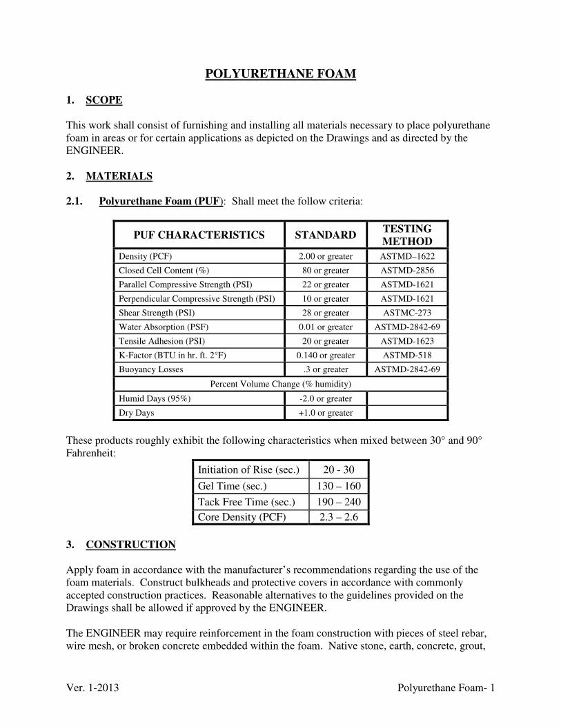
Ver. 1-2013 Polyurethane Foam- 1
POLYURETHANE FOAM 1. SCOPE
This work shall consist of furnishing and installing all materials necessary to place polyurethane foam in areas or for certain applications as depicted on the Drawings and as directed by the ENGINEER. 2. MATERIALS
2.1. Polyurethane Foam (PUF): Shall meet the follow criteria:
PUF CHARACTERISTICS STANDARD TESTING
METHOD
Density (PCF) 2.00 or greater ASTMD–1622
Closed Cell Content (%) 80 or greater ASTMD-2856
Parallel Compressive Strength (PSI) 22 or greater ASTMD-1621
Perpendicular Compressive Strength (PSI) 10 or greater ASTMD-1621
Shear Strength (PSI) 28 or greater ASTMC-273
Water Absorption (PSF) 0.01 or greater ASTMD-2842-69
Tensile Adhesion (PSI) 20 or greater ASTMD-1623
K-Factor (BTU in hr. ft. 2°F) 0.140 or greater ASTMD-518
Buoyancy Losses .3 or greater ASTMD-2842-69
Percent Volume Change (% humidity)
Humid Days (95%) -2.0 or greater
Dry Days +1.0 or greater
These products roughly exhibit the following characteristics when mixed between 30° and 90° Fahrenheit:
Initiation of Rise (sec.) 20 - 30
Gel Time (sec.) 130 – 160
Tack Free Time (sec.) 190 – 240
Core Density (PCF) 2.3 – 2.6
3. CONSTRUCTION
Apply foam in accordance with the manufacturer’s recommendations regarding the use of the foam materials. Construct bulkheads and protective covers in accordance with commonly accepted construction practices. Reasonable alternatives to the guidelines provided on the Drawings shall be allowed if approved by the ENGINEER. The ENGINEER may require reinforcement in the foam construction with pieces of steel rebar, wire mesh, or broken concrete embedded within the foam. Native stone, earth, concrete, grout,

Ver. 1-2013 Polyurethane Foam- 2
and aggregates may be required for forming efforts as needed. Construct bulkheads from similar materials and common construction materials such as wood, plastic, sheet metal, tin and fibrous materials. Remove any flammable materials used in the outer bulkheads after the foam hardens and before required cover material placement. Foam must be applied in layers allowing each successive layer to expand, cool, and harden before the next layer can be applied. Do not place successive layers to foam while a previous layer is currently expanding. Apply foam in such a manner that will fill the voids in the portal and not create pockets inside the foam plug and shall form a solid wall around pipes at the outer barrier. Backfill the entire surface of the foam plug with 2 feet minimum of earth materials/aggregate or 1 foot minimum of grout combined with cobbles or boulders. Backfill shall form a fire resistant ultra-violet proof cover for the foam plug.
Ver. 1-2013 Portal Closure- 1
PORTAL CLOSURE 1. SCOPE
This work shall consist of furnishing and installing all materials, equipment, incidentals, and labor necessary to properly seal mine portals as shown on the Drawings to prevent human access. The ENGINEER may revise the type of closure used depending on conditions encountered at the time of construction. Where it is determined that the particular mine portal is considered habitat for bats or that bats are present, the opening shall be closed using at least a 36 inch dia. pipe or bat gate. 2. MATERIALS
2.1. Concrete: Shall be Class A concrete conforming to the “Concrete” technical specification. 2.2. Concrete Block: Shall conform to ASTM C-129. 2.3. Mortar: Strength shall meet AASHTO T-71. 2.4. Pipe: Shall be high density polyethylene pipe (HDPE) conforming to the “Pipe” technical specification. 2.5. Rock: Shall be Class II channel lining, No. 57, No. 8, No. 9, 9 crushed aggregate, and pea gravel conforming to the “Crushed Aggregate and Channel Lining” technical specification. 2.6. Doors: Shall be 1/4 inch steel plate or equivalent equipped with suitable hinges, hasp, and padlock. The door shall be securely anchored to the concrete block and secured by a lock. 2.7. Filter Fabric: Shall conform to the “Filter Fabric” technical specification. 2.8. Steel Bars: Shall be No. 4 steel reinforcement conforming to the “Steel” technical specification. 2.9. Polyurethane Foam: Shall conform to the “Polyurethane Foam” technical specification. 2.10. Pneumatic Backstow: Shall conform to the “Pneumatic Backstowing” technical specification. 2.11. Paint: Shall be a commercially available rust inhibiting product either black or brown color.
Ver. 1-2013 Portal Closure- 2
3. CONSTRUCTION METHODS
3.1. General: Remove all debris, rubble, and other loose material from the mine openings in a prudent fashion prior to beginning construction of the closure, unless a dangerous safety hazard exists. Begin excavation efforts at the top of the loose material pile or dangerous overhang of each designated portal and proceed incrementally downward until all of the material has been removed down to grade. As excavation work proceeds, be watchful for the presence of mine water. Immediately
report any mine water detected to the Resident Inspector and halt excavation until the
ENGINEER has granted approval to proceed further. DAML will test and shall meet the
requirements of the “Water Treatment and Disposal” section of these Technical
Specifications. When the ENGINEER approves work to continue, control the flow rate of
all mine water effluent to proper sediment control structures.
Soil and rock may be placed in the mine openings provided they do not interfere with drainage or the construction specified in the Drawings. Dispose of all other materials in an approved waste area. Following construction clean up each site including smoothing earth disturbance, and revegetate in accordance with the “Revegetation” technical specification. This work is incidental to each mine closure. 3.2. Concrete Block: Construct the closure using solid concrete block (8 x 8 x 16 inch) with the exception of vent holes. Place a filter fabric wrapped drainage pipe in the base of the opening. Set the blocks set on a concrete footer and fill the top and sides with mortar. 3.3. Concrete Block with Human Access: Construct the closure as a concrete block closure, however, add an entry door. Install the drainage pipe below the entry door, but above the mine floor. 3.4. Standard Non-Wildlife Accessible Rock Closures: Insert a drainage pipe wrapped in filter fabric into the mine opening and protect by covering with No. 57 stone before placing backfill. Backfill with sufficient pneumatically backstowed pea gravel or Class II channel lining to allow proper closure of the mine workings and allowing for shrinkage or slumping of the material. 3.5. Standard Wildlife Accessible Closures: 3.5.1. Wildlife Closure w/ Pipe: Insert a HDPE culvert (36 inch dia. when possible) with a 1/2 inch reinforcing bars grate recessed in the pipe. Backfill with sufficient pneumatically backstowed pea gravel or Class II channel lining to allow proper closure of the mine workings and allowing for shrinkage or slumping of the material. 3.5.2. Wildlife Closure with Grate/Bars: Insert grates or bars set in concrete.

Ver. 1-2013 Portal Closure- 3
Where there is a dangerous overhang place the closure far enough from the opening where workers will not be directly under the overhang. The grate or bars must cover the opening on all sides. The bars may be bent so that they touch the dangerous areas preventing access. 3.6. Polyurethane Foam Closures (PUF): Construct these closures with layers of polyurethane foam and wildlife accessible or non-wildlife accessible pipe. Cover the face of the closure with either 2 inches of grout or 2 feet of rock and earthen materials.
Ver. 1-2013 Reinforced Concrete Pilings & Cap- 1
REINFORCED CONCRETE PILINGS AND CAP
1. SCOPE
This work shall consist of furnishing and installing all materials, equipment, incidentals, and labor necessary to construct reinforced concrete pilings and caps as shown on the Drawings. 2. MATERIALS 2.1. Concrete: Shall be Class AA concrete conforming to the “Concrete” technical specification. 2.2. Steel Reinforcement: Shall conform to the “Steel” technical specification. 2.3. Casings: Shall provide sufficient sidewall strength to allow insertion of reinforcing steel and concrete and maintain the diameter of the hole through placement of the concrete. 3. CONSTRUCTION
The CONTRACTOR shall drill the holes of the diameter and depths stated on the Drawings and as directed by the ENGINEER. The CONTRACTOR will ensure that each hole will remains open. This may require the use of casing materials. Water shall be pumped from the holes prior to placement of concrete. Concrete shall be placed in a manner that will ensure the concrete does not fall an unacceptable distance as stated in the “Concrete” technical specification.
Ver. 10-2015 Revegetation- 1
REVEGETATION
1. SCOPE
The work will consist of furnishing all labor, equipment, and materials for preparing the seedbed; applying soil amendments, seed, mulch, and installing netting. All disturbed areas are to be revegetated unless another surface treatment is specified for the area on the Drawings or Special Conditions. Areas brought to final grade shall be revegetated within 5 days. Apply temporary mulch and a cover crop to areas that are not to final grade, areas where constructed has ceased for 14 days or longer, and soil stock piles no later than 14 days from the last construction activity. 2. MATERIALS
2.1. Lime: Agricultural ground limestone (ag-lime) or its equivalent shall be used. The ground limestone must have minimum 85% calcium carbonate (CaCO3) equivalent, must be fine enough so that no less than 90% passes through a U.S. Standard No. 10 sieve, and no less than 35% passes through a U.S. Standard No. 50 sieve. Agricultural ground limestone shall be purchased from quarries tested by the Kentucky Department of Agriculture. Ag-lime that fails to meet the minimum requirements may be used, but additional ag-lime must be added at no extra cost to the COMMONWEALTH to make up the deficiency using the relative neutralizing value (RNV) calculation based upon values from the current KY Department of Agriculture Division of Regulation and Inspection “Limestone Sample Test” report. On excavated to bedrock areas ag-lime or rock dust shall be used if it meets the above standards and if 100% shall pass through a U.S. Standard No. 50 sieve. 2.1.1. Relative Neutralizing Value Calculation: Shall be calculates as:
RNV = % CaCO3 / 100 x 0.5 x (% passing through No. 10 sieve + % passing No. 50
sieve). The minimum value based upon the DAML standard is 53.125. The additional quantity required is calculated as:
Reported RNV / 53.125 (AML Minimum) x tons provided
No adjustments / incidental additional quantities are required if the materials meet or exceed the minimums. Any additions required due to deficient material are entirely bore by the CONTRACTOR. 2.2. Fertilizer: The fertilizer shall be a commercial fertilizer containing the plant nutrients of nitrogen (N), available phosphoric acid (P205), and soluble potash (K20). Bagged fertilizer shall display the following information on the bag or on a sticker or tag attached to the bag: net weight, brand and grade, guaranteed analysis, and name and address of manufacturer. Bulk fertilizer (dry or liquid) shall be accompanied by a statement from the manufacturer, which contains the same information required for the bagged fertilizer. Either bagged or bulk (dry or
Ver. 10-2015 Revegetation- 2
liquid) fertilizer must be manufactured and sold under the jurisdiction of the Division of Regulatory Services of the University of Kentucky Agricultural Experiment Station. 2.3. Seed: Seed is paid as “PURE LIVE SEED”. Apply seed to all disturbed areas in accordance with the seed mixture tables in APPENDIX A with no alterations except with the written consent of the ENGINEER. See APPENDIX A for the formula to calculate pure live seed. The seed mixture shall be totally free of any quack grass, dodder, Johnson grass, Canada thistle seed, and contain less than 2% weed seed. The number of noxious weeds per pound shall not exceed a combined total of 30 seeds per pound. The seed shall also comply with all Kentucky seed laws and regulations (KRS 205.020 to 250.170). Furnish seed bags fully tagged and labeled in accordance with the State laws and the U.S. Department of Agriculture Rules and Regulations under the Federal Seed Act in effect on the date of invitations for bids. All seed must be from the latest crop available. No seed will be accepted with a date of test of more than 9 months prior to the date of delivery to the site. Any seed, which has become wet, moldy, or otherwise, damaged in transit or storage will not be accepted. All seed shall be delivered in separate bags or packages according to species. The ENGINEER’s representative at the site shall remove the tags from each seed bag. These tags will be required for final payment. Pre-mixed seed will not be accepted. All legume seed shall be treated with inoculants prior to seeding in accordance with this section of these Technical Specifications. All legume seeds shall be applied separate from all other grass seed, unless a hydraulic seeder is used. Any and all seeding of lespedeza species (i.e., Kobe, Korean, and Sericea) will require unhulled seeding during the period of July 1 to December 31. Hulled and scarified seed will be required during the period of January 1 to June 30. The percent of hard seed shall be considered as part of the germination rate. 2.4. Mulch: Mulch shall consist of hay or straw. The mulch material shall be air dry, reasonably light in color, low in weed content, and shall not be musty, caked, or otherwise of low quality. Mulch containing thistles, Johnson grass, or wild onion is not permitted. On excavated to bedrock areas, hydro-mulch shall be cellulose fiber or processed straw. Delivery is only permissible when the Resident Inspector is on the job site. 2.5. Hardwood Bark Mulch: This material is a composted hardwood bark mulch product free of noxious weeds or debris produced from trees. The product should be composted and have a moisture content no greater than 50%. The mulch pieces should be less than 3 inches long x 1inch wide.
Ver. 10-2015 Revegetation- 3
2.6. Netting: Plastic netting manufactured from extruded rectangular mesh plastic, a minimum of 45 inches wide, approximately 3/4 inch x 1 inch mesh openings, and weighing no less than 2.6 lbs. per 1,000 sq. ft. shall be used. Other netting may be used if approved by the ENGINEER. Staples will be U-shaped and made from No. W1-W1.5 or W2 steel wire or a manufactured recommended product. The staples shall have a minimum length of 6 inches. Staples shall be driven flush with soil surface. 2.7. Tack: Tack is an organic tackifier used during hydromulch / hydroseeding and applied at the manufactures recommended rate. 2.8. Inoculants: The inoculants for treating legume seeds shall be a pure culture of nitrogen-fixing bacteria prepared specifically for the species and shall not be used later than the date indicated on the container or otherwise specified. Use the amount of the inoculants recommended by the manufacturer except when seed is applied by use of a hydraulic seeder, and then four times the amount of inoculants recommended by the manufacturer shall be used. Seed shall be sown within 24 hours of treatment and shall not remain in a hydraulic seeder longer than 4 hours. 2.9. Cover Crop: Apply the material whenever the project is to be shut down for greater than 14 days. Use winter wheat for fall/winter seeding and German foxtail millet for spring/summer seeding at 1 bushel per acre. 2.10. Disk: The disk shall be either a tandem or offset disk meeting the following specifications:
1) Disk size: 22-inches minimum. 2) Disk spacing: 13-inches maximum. 3) Weight: 400 lbs. per foot of cut minimum. 4) Equipped with a drag of sufficient weight to remove any furrows left by the disk.
3. CONSTRUCTION
3.1. Lime: Apply agriculture limestone to the site and incorporate into the upper 6 inches (min.) with the fertilizer. Application on strip to rock areas is not incorporated. Supply a blower or side casting type piece of equipment to apply lime to steep slopes (incidental). For acidic soil incorporate lime into the borrow material during excavation. The general application rate is 10 tons per acre furrow slice for surface soils. For acidic soil the application rate may be increase to 25-100 tons per acre furrow slice and be either incorporated throughout the cover material during harvesting or applied as an agriculture limestone barrier. The Design Drawings and Special Conditions will note when the large application rates are required. Delivery is only permissible when the Resident Inspector is on the job site.
Ver. 10-2015 Revegetation- 4
3.2. Fertilizer: Apply fertilizer only when it can incorporate into the soil the same work day without the threat of large scale precipitation events. Generally, the application rate will be 0.35 tons/acre of an 18-46-60 mixture made from mixing 500 lbs of 18-46-0 and 200 lbs 0-0-60 fertilizers together. If a second application is required by the ENGINEER within 1 year of the original application then a generally application of 100 lbs/acre of 33-0-0 should be used. These rates do not apply if a different rate is stated on the Design Drawings, Special Conditions, or instructed by the Engineer. 3.3. Seedbed Preparation: Immediately following final grading, the areas to be seeded shall be dressed to a reasonably smooth, firm surface as determined by the Resident Inspector. Till the surface to a minimum depth of 6 inches with either a tandem or offset disk. Suspend seedbed preparation when soil conditions are not suitable for the preparation of a satisfactory seedbed. The ENGINEER’s designee shall make this determination. On slopes too steep to disk use tracked equipment to "walk-in" and break up the surface of the soil prior to seeding (incidental) with the track groves parallel to the slope contours. 3.4. Seeding: Apply the specified mixtures of pure live seed (PLS) on all disturbed areas within the project limits designated on the Drawings using the seasonal variations shown immediately following seedbed preparation. In the event the date does not concur with the seeding schedules specified, seeding shall be accomplished using any one of the specified rates or an equivalent rate designed to fit the site and weather conditions, as directed by the ENGINEER. Broadcast the seed evenly over the area immediately following tilling using a cyclone seeder, hydroseeder, or equivalent (incidental). Hydroseeder slurry water pH must remain above a pH of 5.0 and the CONTRACTOR shall provide an accurate pH meter to monitor the slurry at all times. The use of a hydroseeder is only paid when designed on the Drawings and Special Conditions. 3.5. Mulching: The mulch shall be applied uniformly over all seeded areas to obtain at least 90% cover. Mulch application must immediately follow seeding unless otherwise noted. Clumps of mulch must be spread. Hardwood bark mulch may be prescribed on the Drawings for acidic soils with low organic matter in lieu of mulch. The Drawings for project documents will specify the application rate.
3.6. Crimper: Crimping shall be performed immediately following mulching. On all designated areas that require crimping, a crimper meeting the following specifications shall be used: 1. Minimum disk size: 20 inches 2. Minimum depth spacing: 8 inches 3. Minimum depth of crimping: 3 inches 4. Minimum weight: 1,300 pounds*
Ver. 10-2015 Revegetation- 5
*This weight can be increased at the discretion of the ENGINEER if soil conditions warrant such an increase.
3.7. Netting: Install netting on all slopes exceeding 30% (3:1 and steeper slopes). Overlap the netting a minimum of 6 inch with previous row. Apply staples at 4 feet maximum spacing on all edges and laps, with interior rows of staples at a 4 feet maximum spacing and spaced in the row at 8 feet maximum spacing. Staples in an interior row shall alternate in spacing with staples on an adjacent interior row. All staples shall be driven flush with the soil surface. 3.8. Hydromulch & Hydroseeding: The equipment, hydromulch, seed, lime, fertilizer,
and tack are all incidental to the bid item. The ENGINEER will only pay for the use of a hydroseeder when used to apply hydromulch on project areas specified in the Drawings, Special Conditions, and on all areas where soil material has been removed to bedrock. No seedbed preparation or netting is required on these areas. Hydro-mulch, either cellulose fiber or processed straw, shall be used and applied at a net dry rate of 1,500 pounds per acre. Mix the cellulose fiber with water to attain a mixture with a maximum of 50 pounds cellulose fiber per 100 gallons of water. Use the seed mixture stated in the Drawings and/or Special Condition. Apply agriculture lime or rock dust at 1 ton/acre and fertilizer at 0.35 tons/acre of an 18-46-60 mixture made from 500 lbs of 18-46-0 and 200 lbs 0-0-60 fertilizers. 3.9. Residential Seeding: This includes seedbed preparation, lime, seed, fertilizer, mulch
and any other material or items necessary to complete the required work. In areas around houses, lime, fertilizer, and seeding rates will vary and additional seedbed preparation work will be required for revegetation of residential areas. Hydrated lime (90% CaCO3 equivalent content and 85% passing a #200 sieve) shall be applied at a rate of 20 pounds per 1,000 square feet. Fertilizer will be applied at a rate of 15 pounds per 1,000 square feet using a "10-10-10" fertilizer. Seed shall consist of a 3:1 mixture of turf type fescue (NOT KY31) and Perennial Ryegrass applied at a combined rate of 4 pounds (PLS) per 1,000 square feet. Additional seedbed preparation shall be required to remove all rock and debris larger than 2 inches and to rake the area to a completely smooth surface. Do not seed on hard ground. Hand raking and tilling will be required. Straw only mulch shall be applied at rates indicated in these Technical Specifications following all other operations. 3.10. Landscape Allowance: This shall consist of replacement “in kind” of any landscape in and around residential areas as part of normal construction techniques to facilitate the completion of other construction bid items. “In Kind” shall be determined in writing by the ENGINEER prior to the disturbance. When approved, landscape to be replaced shall be of the same species. To qualify for reimbursement, advanced approval from the ENGINEER must be given for removal and subsequent replacement. All removal and replacement shall be documented by the inspector. Any landscape damaged due to CONTRACTOR carelessness shall be replaced at the CONTRACTOR’S expense.
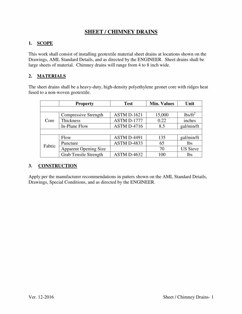
Ver. 12-2016 Sheet / Chimney Drains- 1
SHEET / CHIMNEY DRAINS
1. SCOPE
This work shall consist of installing geotextile material sheet drains at locations shown on the Drawings, AML Standard Details, and as directed by the ENGINEER. Sheet drains shall be large sheets of material. Chimney drains will range from 4 to 8 inch wide. 2. MATERIALS
The sheet drains shall be a heavy-duty, high-density polyethylene geonet core with ridges heat fused to a non-woven geotextile.
Property Test Min. Values Unit
Core
Compressive Strength ASTM D-1621 15,000 lbs/ft2
Thickness ASTM D-1777 0.22 inches
In-Plane Flow ASTM D-4716 8.5 gal/min/ft
Fabric
Flow ASTM D-4491 135 gal/min/ft
Puncture ASTM D-4833 65 lbs
Apparent Opening Size 70 US Sieve
Grab Tensile Strength ASTM D-4632 100 lbs
3. CONSTRUCTION Apply per the manufacturer recommendations in patters shown on the AML Standard Details, Drawings, Special Conditions, and as directed by the ENGINEER.
Ver. 12-2013 Sheet Piling- 1
SHEET PILING 1. SCOPE
This section describes the types of steel sheet piling used during construction. The actual size and placement of the products are noted on the Drawings and/or as directed by the ENGINEER. 2. MATERIALS Steel shall be kept free from dirt, grease and other foreign matter, and shall be protected from corrosion. 2.1. Sheet Piling: Shall be made in accordance with ASTM A 857 from steel meeting the requirements of ASTM A 1011, Grade 30. The sides of each piece of sheeting shall be furnished with an interlock that is continuous for the full length of the sheeting. The interlock shall have an opening of sufficient width to allow free slippage of the adjoining sheet. 2.2. Galvanized Coating: When required, the sheeting shall be hot-dipped galvanized per ASTM A 123 at a rate of two ounces per square foot total both sides. 3. CONSTRUCTION
Install the piling per the manufacturer recommendations and as directed by the ENGINEER. Sheet Piling shall be driven by equipment recommended by the manufacturer. Damage to sheet piling as a result from improper driving equipment may result in the COMMONWEALTH refusal to pay for the damaged sheet piling.
Ver. 1-2013 Shotcrete Application- 1
SHOTCRETE APPLICATION
1. SCOPE This work shall consist of constructing a pneumatically applied shotcrete blanket onto rock/soil surfaces at locations shown on the Drawings or as directed by the ENGINEER. These specifications refer to premixed cement and aggregate pneumatically applied by suitable equipment and competent operators. 2. MATERIALS
2.1. Shotcrete: Shall conform to the “Grout Products” technical specification. Either wet-mix or dry-mix shotcrete may be used. The shotcrete shall be reinforced with either welded wire fabric or steel fibers. The shotcrete shall be applied according to these Technical Specifications and applicable sections of the American Concrete Institute’s Guide to Shotcrete (ACI 506R-85). The contractor shall be responsible for the design of shotcrete mixes and for the quality of shotcrete placed. 2.2. Steel Fiber Reinforcement: When the Drawings or Technical Specifications require the use of steel fiber reinforced shotcrete, the steel fiber reinforcement shall meet the following requirements. Steel fibers shall have a length between 1 to 1-3/8 inches, have blunt or hooked ends, have a length to diameter ratio of less than 80, and shall be cold drawn carbon steel with a minimum tensile strength of 160,000 psi. Only steel fibers manufactured specifically for use in shotcrete applications will be allowed. The steel fiber content shall not be less than one hundred (100) pounds for each cubic yard of shotcrete. The steel fibers must be premixed with the cement. 2.3. Acceptance Sampling and Testing: 2.3.1. General: Prepare shotcrete test panels on vertically supported molds. Test panels shall be approximately 24 x 24 inches by a minimum of 3 inches deep. The material used to form the back and sides of the molds shall be rigid, nonabsorbent and be non-reactive with cement. Accomplish the shotcrete placement in vertical molds utilizing the same shotcrete mix, air and water pressure, and nozzle tip as used for the actual placement of shotcrete on production surfaces. Leave the panels undisturbed and protected at the point of placement for at least 24 hours or until the final set has taken place. Apply the shotcrete to a thickness of 3 to 3-1/4 inches with no sagging.
2.3.2. Preproduction Testing: Prepare at least two test panels for each mix design for testing. The test panels shall be cured using the approved curing compound in a manner similar to the anticipated field conditions. The ENGINEER shall receive a copy of the mix design and the compressive test results at least 5 days prior to starting any production work. Production shotcrete work shall not begin until satisfactory test results are obtained.
Ver. 1-2013 Shotcrete Application- 2
2.3.3. Failure of Shotcrete: Should any shotcrete section be deficient in any of the specified criteria, that section shall be remedied to the ENGINEER’s satisfaction at the CONSTRACTOR’s expense. Such remedies may include, but not be limited to, removal and replacement of the substandard section.
2.4. EQUIPMENT
2.4.1. Pump System: The pump system used to convey premixed shotcrete ingredients shall deliver a uniform and uninterrupted flow of material without segregation or loss of the ingredients. The mixing equipment shall be capable of thoroughly mixing the specified materials in sufficient quantity to maintain continuous placing.
2.4.2. Air Compressor: The air compressor shall be capable of maintaining a supply of clean air adequate for maintaining sufficient nozzle velocity for all parts of the work and for the simultaneous operation of a blow pipe for clearing away rebound. The compressor shall be capable of providing a minimum of 250 cubic feet per minute per operating nozzle. 2.4.3. Batching and Mixing Equipment: The mixing equipment shall be capable of thoroughly mixing the materials to maintain continuous application.
2.4.4. Dry Mix Process Delivery Equipment: The equipment shall be capable of discharging the aggregate-cement mixture into the delivery hose and delivering a continuous stream of uniformly mixed material to the discharge nozzle. The discharge nozzle shall be equipped with a manually operated water injection system (water ring) to direct an even distribution of water through the aggregate-cement mixture. The water valve shall be capable of ready adjustment to vary the quantity of water and shall be convenient to the nozzleman. The water pressure at the discharge nozzle shall be greater than the operating air pressure to assure that the water is thoroughly mixed with the other material. The water pressure shall be steady (non-pulsating). Equipment parts, especially the nozzle liner and water ring, shall be regularly inspected and replaced as required. 2.4.5. Wet-Mix Process Delivery equipment: The equipment shall be capable of discharging the premixed materials into the delivery hose and delivering a continuous stream of uniformly mixed material to the discharge nozzle. Recommendations of the equipment manufacturer shall be followed for the type and size of nozzle to be used and for cleaning, inspection, and maintenance of the equipment. 3. CONSTRUCTION
3.1. Contractor Qualifications: At least 30 days prior to beginning shotcrete work, the contractor shall provide written evidence that the supervisor, nozzle operator, and delivery equipment operator have performed satisfactory work in similar capacities elsewhere for a sufficient length of time to be fully qualified to perform their duties.
Ver. 1-2013 Shotcrete Application- 3
The supervisor shall not have less than 2 year’s experience as a shotcrete nozzle operator. The nozzle operator and delivery equipment operator shall have served at least 1 year of apprenticeship on similar applications with the same type of equipment. Prior to the start of shotcreting work, nozzle operators shall, in the presence of the ENGINEER, demonstrate their ability to apply shotcrete of the required quality on a test panel. One satisfactory test panel shot in a vertical position for each mix design used during the course of the work shall be the minimum qualification test for nozzle operators before they will be permitted to place shotcrete. 3.2. Surface Preparation: Immediately prior to shotcrete / rock fall netting application, rock surfaces of the areas to be shotcreted scale of all contaminating and loose material and thoroughly clean by use of air or water jets, or other means approved by the ENGINEER, in order to provide a suitable bonding surface (see “Highwall-Slope Rockfall Netting Light Duty” technical specification). Clean soil surfaces of loose material by using an air jet. Shotcrete shall not be placed on any surface that is frozen, spongy, or where there is free water. The surface shall be dampened before applying shotcrete. 3.3. Shotcrete Blanket Thickness Control: The thickness of the shotcrete blanket shall be controlled by installing noncorrosive pins, nails, or other gauging devices normal to the face, such that they protrude the required shotcrete thickness outside the face. These pins shall be placed on a maximum 8foot square pattern. When rockfall netting reinforcement is used, a minimum 1 inch cover of shotcrete shall be placed over the welded wire fabric.
The lower 2 feet of the rock slope shall not be shotcreted to allow drainage. 3.4. Weep Holes: Unless otherwise shown on the plans, weep holes shall be provided throughout the shotcrete mat at 10 foot centers maximum, horizontal and vertical. The weep holes shall be in contact with open points in the natural rock. Prior to shotcreting, survey stakes shall be driven into open joints. Shotcrete shall be applied around the stakes. After the shotcrete has reached the initial set, the stakes shall be removed to leave the drain hole open. 3.5. Batching and Mixing Shotcrete: 3.5.1. Dry-mix Process: The cement and aggregate shall be batched by weight. Pre-dampening shall be carried out prior to flow into the main hopper and immediately after flow out of the packing in order to ensure that the premix will flow at a uniform rate (without slugs) through the main hopper, delivery hose and nozzle to form uniform shotcrete, free of dry pockets. No pre-dampened cement/aggregate mix shall be used if allowed to stand for more than 90 minutes.
3.5.2. Wet-Mix Process: Batching and mixing shall be done according to the applicable provisions of ASTM C 94. 3.5.3. Batching and Mixing Steel Fibers: Steel fibers shall be premixed with the cement prior to batching shotcrete.
Ver. 1-2013 Shotcrete Application- 4
3.6. Shotcrete Application: Unless shown on other plans, the minimum thickness of shotcrete shall be 2 inches and the maximum thickness shall be 3 inches for steel fiber reinforced shotcrete. Where rockfall netting is used, the mesh shall be covered with a minimum of 1 inch of shotcrete (3 inch total thickness approx.). Apply the shotcrete from the lower portion of the area upward so that rebound does not accumulate on the portion of the surface that still has to be covered. Work rebound material into the finished product. Rebound is defined as the shotcrete constituents that fail to adhere to the surface to which shotcrete is being applied. It shall not be salvaged and included in later batches. Shotcrete shall emerge from the nozzle in a steady uninterrupted flow. When, for any reason, the flow becomes intermittent, the nozzle shall be diverted from the work until steady flow resumes. A nozzleman’s helper, equipped with an air blowout jet, shall attend the nozzleman at all times during the placement of shotcrete to keep the working area free from rebound. Suspend shooting if high winds prevent the nozzleman from proper application of the material,
the temperature is below 40°F, or external factors, such as rain or seepage, wash cement out of the freshly placed material or cause sloughs in the work, Construction joints shall be tapered over a minimum distance of 12 inches to a thin edge and the surface of such joints shall be thoroughly wetted before any adjacent section of mortar is placed. Square construction joints shall not be permitted. The surface shall be sounded with a hammer for unsound areas resulting from rebound pockets or lack of bond. Carefully cut out and replace sags and defects with a succeeding layer at the contractor’s expense. When fabric reinforcement is damaged or destroyed by repairs, the damaged area shall be replaced by properly lapping and tying additional the replacement and existing wire fabric sections together. Where a layer of shotcrete is to be covered by a succeeding layer, allow the first layer take its initial set. Clean the initial layer of all loose material prior to placing succeeding layers. 3.7. Finishing: The shotcrete surface shall be completed in the natural gun finish. 3.8. Curing: Apply a white pigmented, liquid membrane-forming curing compound immediately after gunning. The air in contact with shotcrete surfaces shall be maintained at temperatures above freezing for a minimum of 7 days. Do not use curing compounds on any surfaces against which additional shotcrete or other cementitous finishing materials are to be bonded unless positive measures, such as sandblasting, are taken to completely remove curing compounds prior to the application of such additional materials.
Ver. 12-2014 Silt Control- 1
SILT CONTROL 1. SCOPE
This work shall consist of furnishing all materials, equipment, labor, and incidentals necessary for the installation of silt control facilities depicted on the Drawings and as directed by the ENGINEER. These structures shall be installed prior to any surface disturbance. 2. MATERIALS
2.1. Silt Barrier- Bales: Shall be either straw or hay bales, firmly bound by twine, and installed using wooden stakes as shown in the Drawings 2.2. Silt Barrier- Fence: Shall conform to AASHTO M-288 for temporary silt fence. Provide fabric with a minimum height of 3 feet. 2.3. Silt Barrier- Wattles: Shall be either straw or koir logs either 6 inch or 9 inch diameter. 2.4. Silt Check- Geotextile Bags: Shall be non-woven medium weight filter fabric that is double stitched with polyester thread and filled with either No. 57 stone or sand and shall be between 50-60 pounds full. 2.5. Baffles: Shall be made from pressure treated lumber and marine plywood forms used to lengthen flow paths in sediment basins. 2.6. Wooden Stakes: Shall be hardwood, greater than 4 feet long, minimum of one and a minimum of 1-1/2 square post straight enough to provide a fence without misalignment. 2.7. Fasteners: Use No. 9, one-inch long, wire staples, and/or fabric ties. 2.8. Stone: Shall conform to the “Crushed Aggregate Section and Channel Lining” technical specification.
2.9. Gabions: Shall conform to the “Gabion” technical specification.
2.10 Geotextile Tubes/Bags: Shall be made from heavy weight non-woven geotextile with double stitched seams using high strength thread per the “Filter Fabric” technical specification. Size sleeve to accommodate a maximum 4 inch diameter pump discharge hose. 2.11. Concrete: Shall be Class A concrete conforming to the “Concrete” technical specification.
3. CONSTRUCTION
The ENGINEER shall direct the exact locations, configuration, and dimensions of the various types of silt control at the time of construction. These structures shall be installed prior to any
Ver. 12-2014 Silt Control- 2
surface disturbance. As erodible areas are exposed, construct temporary drainageways where needed to divert runoff from erosive soils to the silt traps. Schedule construction activities so that the amount of exposed soil is minimized. This is to be accomplished by disturbing only those areas, which are to be worked immediately, and by revegetating each area as soon as practical. Silt Structures shall remain in place until the area has a substantial stand of grass to prevent erosion or as directed by the ENGINEER.
3.1. Silt Barrier- Bales: Place bales with 1/2 foot overlap and two stakes per bale. When placed along a contour we will turn the ends and at intervals upslope to prevent water from flowing along the fence. 3.2. Silt Barrier- Silt Fence: Construct continuous and traverse to the flow. Install per manufacturer’s instructions or as shown on the Drawings and AML Standard Details. When placed along a contour we will turn the ends and at intervals upslope to prevent water from flowing along the fence. Overlap the fence when two sections must be tied together. Limit the equivalent runoff area to 1,000 square feet per 10 feet of temporary silt fence. The fence must
be trenched in place.
Silt Fence Design Constraints
Average Slope Steepness Max. Slope Length Max. Silt Fence Length*
Flatter than 5:1 (< 2%) 300 feet Unlimited
50:1 to 10:1 (2-10%) 125 feet 1,000 feet
<10:1 to 5:1 (>10-20%) 100 feet 750 feet
<5:1 (>20%) 40 feet 250 feet
*Maximum length refers to distance between “J” hook sections. 3.3. Silt Barrier- Wattles: Install per manufacturer’s instructions or as shown on the Drawings. 3.4. Silt Check- Geotextile Bags: Shall be placed at the inlet end of all structures such as culverts and drop boxes. 3.5. Silt Check- Rock: Stone silt structures shall be installed at the locations shown on the Drawings or as directed by the ENGINEER and in accordance with the AML Standard Details current edition. This practice is not to be used as a sediment trapping device. Sediment-laden runoff must pass through a sediment trapping practice prior to being discharged from the site. Velocity calculations are to be based on the 2 year, 24 hour frequency storm event. Accumulated sediment must be removed when it reaches one-half the height of the weir crest. Locate stone check dam(s) to provide maximum velocity reduction. This may be achieved by considering the volume of runoff, the drainage area, and the slope. Place stone check dams in reasonably straight sections of the flow channel to minimize the potential for erosion in the channel bend. The height of the stone outlet weir crest must not exceed one-half the depth of the swale. Additionally, the maximum height to the weir crest must not exceed 2 feet to prevent scour at
Ver. 12-2014 Silt Control- 3
the toe of the dam. The stone check dam must extend from bank to bank of the swale with the weir section length in the center of the dam. If these provisions cannot be met, an engineering analysis must be conducted. 3.6. Silt Trap– Type A: These are intended for small watersheds (<2-ares) or in series for sediment laden water. Construct excavated pits from 2-4 feet in depth, 20-30 feet in length, and 5-10 feet in width. Transport excavated materials to the waste area or area designated by the ENGINEER. The ENGINEER may elect to convert this item into a permanent trap using the appropriate AML Standard Detail as a template. Traps need to retain a 3:1 (minimum) flow path. Install baffles or turbidity curtains if the standard design length cannot be obtained (incidental). 3.7. Silt Trap- Type B: Construct excavated pits from 2-4 feet in depth, 20-30 feet in length, and 5-10 feet in width and line the outside with Class II/III to contain all flow with a low spot in the middle of dike to control the flow of water from the area. The rock berm should not exceed 4 feet high. Transport excavated materials to the waste area or area designated by the ENGINEER. The ENGINEER may elect to convert this item into a permanent trap using the appropriate AML Standard Detail as a template. Traps need to retain a 3:1 (minimum) flow path. Install baffles or turbidity curtains if the standard design length cannot be obtained (incidental). 3.8. Silt Check- Gabion: All gabion silt structures shall be installed at locations shown on the Drawings or as directed by the ENGINEER. 3.9. Concrete Weirs: Construct and install concrete weirs into original ground as noted on the Standard Detail. They may be formed and poured in place or pre-cast. Pre-cast units may require additional concrete to extend the edges into original ground. 3.10. Silt Check- Tubes/Bags: Install at the locations shown on the Drawings or as directed by the ENGINEER. DAML will test the water flowing from these tubes/tubes to determine if further treatment is required in accordance with the “Water Treatment and Disposal” technical specification. Tightly seal sleeve around the pump discharge hose with a strap or similar devise. Place filter bag on suitable base (e.g. mulch, woodchips, sand, or straw bales) located on a level or 5% (max) sloping surface. Discharge to a stabilized area. Extend base a minimum of 12 inches from edges of bag. Control pumping rate to prevent excessive pressure within the filter bag in accordance with the manufacturer recommendations. As the bag fills with sediment, reduce pumping rate. Remove and properly dispose of filter bag upon completion of pumping operations or after bag has reached capacity, whichever occurs first. Spread the dewatered sediment from the bag in an approved upland area and stabilize with seed and mulch by the end of the work day. Restore the surface area beneath the bag to original condition upon removal of the device. Replace filter bag if bag clogs or has rips, tears, or punctures. During operation keep connection between pump hose and filter bag water tight. Replace bedding if it becomes displaced.
Ver. 12-2014 Silt Control- 4
3.11. Perimeter Dike & Swale: Construct around the project area to prevent adjacent clear surface runoff from crossing onto actively disturbed soils within the project area. Remove and dispose of trees, brush, stumps, obstructions, and other objectionable material so as not to interfere with proper function of the dike/swale. Excavate or shape the dike/swale to line, grade, and cross section as specified on the Drawings and/or Special Conditions. Bank projections or other irregularities are not allowed. Construct dike/swale on an uninterrupted, continuous grade, adjusting the location due to field conditions as necessary to maintain positive drainage. Stabilized the channel by lining with Type A ECB and seed or heavy weight non-woven filter fabric. Provide outlet protection as required. Stabilize the dike/swale within 3 days of installation. Stabilize dike/swales used for clear water diversion within 24 hours of installation. Maintain line, grade, and cross section. Remove accumulated sediment and debris, and maintain positive drainage. Keep perimeter dike/swale and point of discharge free of erosion. Upon removal grade area flush with existing ground and vegetate within 24 hours. 3.12. Maintenance: The Resident Inspector will inspect all erosion control devises weekly and after each 0.1-inch rainfall event and notify the CONTRACTOR as to areas that must be addressed. Critical failures will be addressed immediately unless site conditions are too
dangerous. Non-critical items must be corrected within 5 days. All deficiencies and corrections will be recorded in the onsite inspector’s daily report. Critical failures include any area where water leaves the project site. Remove all accumulated silt when the devises are 50% full and place in approved waste areas. Non-critical items are those that would not allow sediment to leave the area without passing through control structures or overland flows that would not cause damage to other property within or outside the project limits. Upon completion of the project, the ENGINEER may direct the CONTRACTOR to remove, clean, or replace silt control structures and revegetate such disturbances in accordance with the “Revegetation” technical specification. Silt control fence (geofabrics) shall be removed and
disposed of properly at the end of construction activities. Failure to install and maintain sediment control throughout the project will result in the
forfeiture of demobilization. Failure to remove silt control fence (geotextile fabrics) shall
result in forfeiture of demobilization.
Following final project acceptance by the ENGINEER, DAML will be responsible for identification and correction of deficiencies regarding ground cover and other storm water BMPs not created because of the CONTRACTOR’S workmanship and/or materials or landowner disturbance.
Ver. 12-2016 Site Preparation- 1
SITE PREPARATION 1. SCOPE
The work shall consist of the clearing, grubbing, and/or stripping of all construction areas as shown on the Drawings, and removing and disposing of any trash and debris within the project limits. In addition, pipe removal and disposal shall be considered part of Site Preparation. 2. CLEARING AND GRUBBING
2.1. Silt Control: Install silt control barriers and temporary diversions as each 200 linear foot section of disturbance occurs. Construct temporary diversion ditches (perimeter dike & swale type) along the contours below areas to be disturbed during construction, prior to disturbance. All disturbed ground must have a sediment control perimeter established at the end of each work day. This includes all temporary clear water diversions, silt barrier (bale & fence), and installation of silt traps where water would leave the project site or the disturbed area. 2.3. Clearing: Trees, snags, logs, stumps, shrubs, rubbish, and garbage shall be removed from the cut and fill areas shown on the Drawings or as directed by the ENGINEER. 2.3. Grubbing: Unless otherwise specified or directed, all stumps, roots, and root clusters having a diameter of 1 inch or larger shall be grubbed out to a depth of at least 1 foot below ground surface in all designated areas. 3. STRIPPING
Strip areas on which excavation or fill operations are to be performed of all vegetation, topsoil, and other organic material. Stripped soil material shall be utilized or disposed of in a manner directed by the ENGINEER. Stockpiling of topsoil-type material will be required. 4. DISPOSAL
All trees cleared from the construction areas, including the waste areas, belong to the surface owners. Transport to and store trees on the individual surface owner's property at locations designated by each owner. Dispose of all remaining cleared and grubbed material as noted on the Drawings, Special Conditions, and as directed by the ENGINEER in a manner not detrimental to the project or the inhabitants of the area. The main disposal method shall be burning and/or windrowing. The contract documents may require chipping for some projects. The CONTRACTOR will be responsible for determining and complying with local ordinances, regarding disposal, and/or burning of such materials.
Ver. 12-2016 Site Preparation- 2
4.1. Chipping: Chip trees up to 20-inch diameter as use as onsite mulch product or for erosion control. The chips may be no larger than 3 inch long and 1 inch wide. 4.2. Windrowing: Create rolled piles generally not exceeding 10 tall and with breaks of greater than 20 feet for every 30 feet of windrowed material. Stack logs >8 inches in diameter in parallel piles in lengths <20 feet. Cut small tree tops and smaller trees into maximum <6 feet lengths and stack in separate parallel piles not to exceed 6 foot in height. Place tree stumps in front of the windrow in an upright position. Do not leave this material in a manner that will create erosion problems or an aesthetically unpleasing feature. 4.3. Burning: Accomplish open burning in strict accordance with current Kentucky Division of Forestry rules and precautions and then only with the approval and under the direction of the ENGINEER. The ENGINEER'S permission to burn and/or his presence at the site shall not be construed as relieving the CONTRACTOR of any responsibility in the event damage occurs or a citizen's complaint arises. The COMMONWEALTH accepts no responsibility for damage or costs associated with burning operations. Before burning, obtain the consent of the landowner on which burning is to be performed, notify adjacent landowners, and use “reasonable precautions" to prevent the escape of fire to adjoining lands. 4.3.1. The "6:00 Burning Law": KRS 149.400 established February 15 through April 30 and October 1 through December 15 as the FIRE HAZARD SEASON. During these fire seasons, everyone is prohibited from burning anything capable of spreading fire within 150 feet of any woodland or brush land, except between the hours of 6:00 p.m. and 6:00 a.m., prevailing local time, or when the ground is covered with snow. 4.3.2. Precautions:
a) WAIT UNTIL AFTER 6:00 P.M. if the weather has been dry and/or windy.
b) Burn only WHEN THE WINDS ARE CALM and there is no chance of gusts.
c) Burn ONLY ON LEVEL GROUND. On slopes and in gullies, a fire can escape more easily and make a fast run uphill.
d) CLEAR THE AREA ten feet around where the fire will be and make sure the
OVERHEAD AREA IS CLEAR.
e) HAVE TOOLS HANDY: a water hose, buckets of water, rakes, hoes, shovels, wet sacks, etc. These can be used to keep the flames inside the cleared area, subdue the flames if the wind picks up or the fire grows too big, smother the fire, or put a control line around it if it is getting out of hand. (More sophisticated equipment may be required by the ENGINEER.)
f) Have more than one person to watch the fire. Be sure THE FIRE IS ATTENDED at all
times by responsible people.
Ver. 12-2016 Site Preparation- 3
g) Watch for SPOT FIRES. Cinders and sparks can carry through the air and start a "spot" of fire off in the distance.
h) FEED THE FIRE SLOWLY. Do not burn everything all at once. This will control the
level of burning and intensity of the fire.
i) Stay with the fire UNTIL THE LAST SPARK IS DEAD OUT. Carefully inspect the burned area the next morning.
j) IMMEDIATELY REPORT out of control escaped fire to the Kentucky Division of
Forestry's local guard or ranger. The local fire department, county dispatcher, or state police may also help if you want to report a forest fire.
4.3.3. Disposal: Dispose of ash and unburned or partially burned debris in a neat and safe fashion, as approved by the ENGINEER. 4.3.4. Restrictions: Burning is not permitted in or adjacent to areas where coarse or fine coal/refuse materials are encountered. 5. MISCELLANEOUS
5.1. Debris Removal and Disposal: Remove domestic household trash & mining debris from the project area (i.e. construction limits, project limits, work limits, etc.) and transport to an appropriate permitted landfill. The ENGINEER must preapprove the landfill. Transport all debris in a safe manner covered or otherwise secured as necessary to prevent loss in transit. 5.2. Pipe Removal and Disposal: Remove and dispose of pipe noted on the Drawings and as directed by the ENGINEER to a permitted landfill. The ENGINEER must pre-approve of the landfill. Transport all debris in a safe manner, being covered or otherwise secured as necessary to prevent loss in transit. 5.3. Temporary Surface Water Diversion Ditches: Construct temporary diversion ditches (perimeter dike & swale type) along the contours below areas to be disturbed during construction, prior to disturbance. 5.4. Temporary Out of Channel Stream Diversions: must use one of the three approved methods: pipe diversion, sandbag/stone channel diversion, and/or fabric-based channel diversion. Do not construct any temporarily diverted channel on bare, erodible soil. No temporary diversion shall be permanent without a 401, 404, and other appropriate permits.
Ver. 4-2014 Soil Nails- 1
SOIL NAILS 1. SCOPE This work shall consist of installing soil reinforcing tubes, netting, and shotcrete (when applicable) at locations shown on the Drawings or as directed by the ENGINEER. 2. MATERIALS 2.1. Bearing Plate: Shall be an 8 inch x 8 inch x 3/8 inch steel bearing plate attached with either a hex nut or by welding to the tubing and securing the wire mesh and reinforcing steel during shotcrete placement. 2.2. Tubing: Shall be round hollow galvanized steel tubing with a nominal outer diameter of 1-1/2 inch and 0.12 inch wall thickness conforming to ASTM A787-05. Tubes will be trimmed flush with the bearing plate. 2.3. Reinforcing Steel: Shall be 60 KSI steel conforming to the “Steel” technical specification. 2.4. Netting: Shall be a triple twisted galvanized wire mesh placed approximately 2 inches between the reinforcing steel and the soil face complying with the “Highwall-Slope Rockfall Netting Light Duty” technical specification. 2.5. Grout: The grout shall have water to cement ratio of 0.6. 2.6. Shotcrete: Shall have a water to cement ratio 0.4 to 0.5 and conform to the Grout Products” and “Shotcrete Application” technical specifications. 3. CONSTRUCTION Prepare the working face as stated on the Design Drawings, in the Special Conditions, or a directed by the ENGINEER. Drill 4 inch dia. holes for the tubing on a spacing stated in the plans or as shown on the AML Standard Detail. Install the tube and inner reinforcing steel rod. Inject grout into the tube until the tube and borehole are filled. After filling the holes install the chimney drains, netting, and reinforcing steel (walers) as shown on the standard detail. The surface will then be covered with shotcrete unless specified otherwise on the Design Drawings or in the Special Conditions.
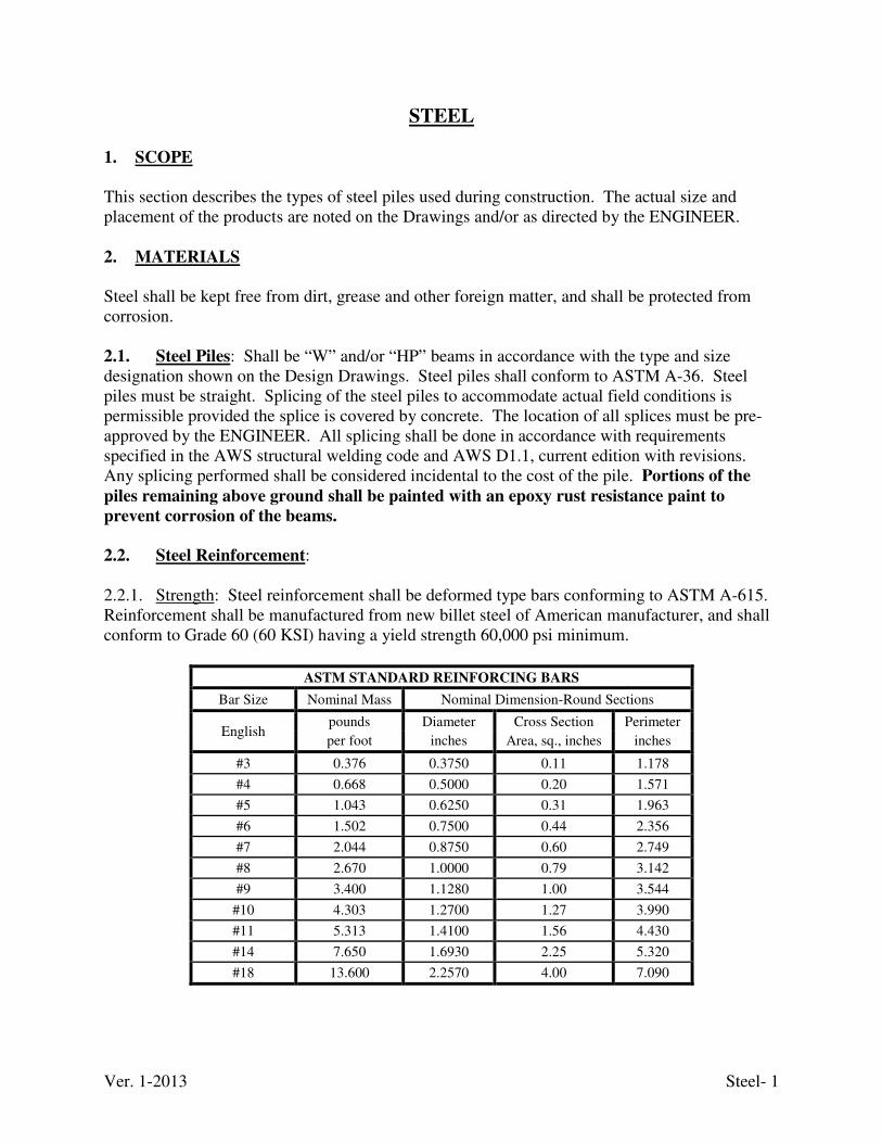
Ver. 1-2013 Steel- 1
STEEL 1. SCOPE
This section describes the types of steel piles used during construction. The actual size and placement of the products are noted on the Drawings and/or as directed by the ENGINEER. 2. MATERIALS Steel shall be kept free from dirt, grease and other foreign matter, and shall be protected from corrosion. 2.1. Steel Piles: Shall be “W” and/or “HP” beams in accordance with the type and size designation shown on the Design Drawings. Steel piles shall conform to ASTM A-36. Steel piles must be straight. Splicing of the steel piles to accommodate actual field conditions is permissible provided the splice is covered by concrete. The location of all splices must be pre-approved by the ENGINEER. All splicing shall be done in accordance with requirements specified in the AWS structural welding code and AWS D1.1, current edition with revisions. Any splicing performed shall be considered incidental to the cost of the pile. Portions of the
piles remaining above ground shall be painted with an epoxy rust resistance paint to
prevent corrosion of the beams.
2.2. Steel Reinforcement: 2.2.1. Strength: Steel reinforcement shall be deformed type bars conforming to ASTM A-615. Reinforcement shall be manufactured from new billet steel of American manufacturer, and shall conform to Grade 60 (60 KSI) having a yield strength 60,000 psi minimum.
ASTM STANDARD REINFORCING BARS
Bar Size Nominal Mass Nominal Dimension-Round Sections
English pounds Diameter Cross Section Perimeter
per foot inches Area, sq., inches inches
#3 0.376 0.3750 0.11 1.178
#4 0.668 0.5000 0.20 1.571
#5 1.043 0.6250 0.31 1.963
#6 1.502 0.7500 0.44 2.356
#7 2.044 0.8750 0.60 2.749
#8 2.670 1.0000 0.79 3.142
#9 3.400 1.1280 1.00 3.544
#10 4.303 1.2700 1.27 3.990
#11 5.313 1.4100 1.56 4.430
#14 7.650 1.6930 2.25 5.320
#18 13.600 2.2570 4.00 7.090
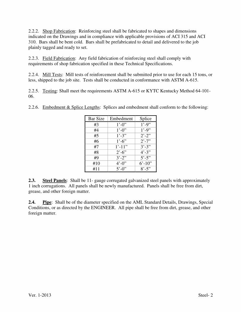
Ver. 1-2013 Steel- 2
2.2.2. Shop Fabrication: Reinforcing steel shall be fabricated to shapes and dimensions indicated on the Drawings and in compliance with applicable provisions of ACI 315 and ACI 310. Bars shall be bent cold. Bars shall be prefabricated to detail and delivered to the job plainly tagged and ready to set. 2.2.3. Field Fabrication: Any field fabrication of reinforcing steel shall comply with requirements of shop fabrication specified in these Technical Specifications. 2.2.4. Mill Tests: Mill tests of reinforcement shall be submitted prior to use for each 15 tons, or less, shipped to the job site. Tests shall be conducted in conformance with ASTM A-615. 2.2.5. Testing: Shall meet the requirements ASTM A-615 or KYTC Kentucky Method 64-101-06. 2.2.6. Embedment & Splice Lengths: Splices and embedment shall conform to the following:
Bar Size Embedment Splice
#3 1’-0” 1’-9” #4 1’-0” 1’-9” #5 1’-3” 2’-2” #6 1’-6” 2’-7” #7 1’-11” 3’-3” #8 2’-6” 4’-3” #9 3’-2” 5’-5”
#10 4’-0” 6’-10” #11 5’-0” 8’-5”
2.3. Steel Panels: Shall be 11- gauge corrugated galvanized steel panels with approximately 1 inch corrugations. All panels shall be newly manufactured. Panels shall be free from dirt, grease, and other foreign matter. 2.4. Pipe: Shall be of the diameter specified on the AML Standard Details, Drawings, Special Conditions, or as directed by the ENGINEER. All pipe shall be free from dirt, grease, and other foreign matter.
Ver. 12-2014 Steel Plates- 1
STEEL PLATES 1. SCOPE
This section covers materials requirements for steel plates and fittings to be used to maintain roadway access. 2. MATERIALS 2.1. Steel Plates: Use base metal for steel plates that conforms to the chemical requirements of ASTM A 569. Ensure that the flat plate, before cold forming, conforms to the following minimum mechanical properties:
Tensile Strength 42,000 psi Yield Strength 28,000 psi Elongation, 2 inches 30%
2.2. Bolts and Nuts: Do not use any bolts and nuts with lapped seams that are less than 5/8 inch in diameter. Provide bolts conforming to ASTM A 449 for plate thicknesses equal to or greater than 0.209 inch and A 307 for plate thickness less than 0.209 inch. Provide nuts conforming to ASTM A 307, Grade A. Only use bolts and nuts with 4-flanged plates of no less than 1/2 inch in diameter for plate thicknesses to and including 0.179 inch and no less than 5/8 inch in diameter for plates of greater thickness.
Ver. 1-2013 Stream Channel Protection & Restoration- 1
STREAM CHANNEL PROTECTION & RESTORATION 1. SCOPE
This item consists of furnishing all materials, equipment, and labor necessary to protect streams during work along or within the channel and constructing and/or reconstructing channels at designated locations as shown on the Drawings, Special Conditions, and as directed by the ENGINEER. Work shall include construction of temporary diversion, riffle structures, pools, bank stabilization utilizing boulders and cobbles excavated from the slide/borrow areas. Work also includes planting trees and shoots at designated locations. NOTE: These items require the ability to identify bankfull stage and Rosgen stream classification. Many of the structure have references to angles that are critical to the overall stability of the structure and stream channel. The placement of all structures must be
designed. 2. MATERIALS
2.1. Filter Fabric: Shall conform to the “Filter Fabric” technical specification. 2.2. Anchor Pins: Shall have a minimum length of 18 inches, and accompanying washers should have a minimum diameter of 1 inch. 2.3. Geotextile Bags: Shall be sand or stone filled bags conforming to the “Silt Control” technical specification. 2.4. Coir: Shall conform to the “Erosion Control Blanket” technical specification. 2.5. Impervious Sheeting: Shall consist of polyethylene or other material which is impervious and resistant to puncture and tearing. 2.6. Logs: Shall be single logs at least 8-10 inches in diameter. Smaller logs may be acceptable provided they are bolted securely together unless noted otherwise on the Drawings, in the Special Conditions, and/or AML Standard Detail. 2.7. Rip-Rap: Shall conform to the “Crushed Aggregate and Channel Lining” technical specification. Size of aggregate is listed on the Drawings, Special Conditions, and/or AML Standard Details. 2.8. Large Rocks: Shall conform to the “Crushed Aggregate and Channel Lining” technical specification. Size of aggregate is listed on the Drawings, Special Conditions, and/or AML Standard Details. 2.9. Vortex Rocks: Shall conform to the “Crushed Aggregate and Channel Lining” technical specification. Size of aggregate is listed on the Drawings, Special Conditions, and/or AML Standard Details. These rocks will be large enough to achieve the desired height when partially
Ver. 1-2013 Stream Channel Protection & Restoration- 2
buried in the stream bed and should be sized to resist movement from shear stresses expected for the design flow. 2.10. Footer Rocks: Shall conform to the “Crushed Aggregate and Channel Lining” technical specification. Size of aggregate is listed on the Drawings, Special Conditions, and/or AML Standard Details. These rocks will be long and flat. 3. CONSTRUCTION
All structures and features are sized to withstand base flow velocities. Transport all excavated material to the designated waste area. Any diversion pipe feature will have a minimum capacity sufficient to convey the 2-year flow for projects with a duration of two weeks or greater. For projects of shorter duration, the capacity of the pipe can be reduced accordingly. Sediment control devices are to remain in place until all disturbed areas are stabilized and the inspecting authority approves their removal.
3.1. Pipe Diversion:
3.1.1. Description: The work should consist of installing flow diversion pipes in combination with sandbag or stone diversions when construction activities occur within the stream channel. 3.1.2. Effective Uses & Limitations: Diversion pipes with an insufficient flow capacity can cause the channel diversion to fail thereby resulting in severe erosion of the disturbed channel section under construction. Therefore, in-channel construction activities should occur only during periods of low flow.
3.2. Sandbag/Stone Channel Diversion:
3.2.1. Description: The work should consist of installing sandbag or stone flow diversions for the purpose of erosion control when construction activities occur within the stream channel. 3.2.2. Effective Uses & Limitations: Diversions are used to isolate work areas from flow during the construction of in-stream projects. Diversions which have an insufficient flow capacity can fail and severely erode the disturbed channel section under construction. Therefore, in-channel construction activities should occur only during periods of low rainfall. This temporary measure may not be practical in large channels. 3.2.3. Construction Notes: Begin construction from upstream to downstream. The height of the sandbag/stone diversion is a function of the duration of the project in the stream reach. For projects with duration less than 2 weeks, the height of the diversion should be one half the stream bank height, measured from the channel bed, plus 1 foot or bankfull height, whichever is greater. For projects of longer duration, the top of the sandbag or stone diversion should correspond to bankfull height (~2-yr flood event). For diversion structures utilizing sandbags, the stream bed should be hand prepared prior to placement of the base layer of sandbags in order to ensure a water tight fit. Additionally, it may be necessary to prepare the bank in a similar fashion.
Ver. 1-2013 Stream Channel Protection & Restoration- 3
Position the impervious sheeting on the diversion such that the upstream portion covers the downstream portion with at least an 18 inch overlap. Sandbag or stone diversions should not obstruct more than 50% of the stream width. Additionally, bank stabilization measures should be placed in the constricted section if accelerated erosion and bank scour are observed during the construction time or if project time is expected to last more than 2 weeks. 3.3. Fabric-Based Channel Diversion: 3.3.1. Description: The work should consist of installing fabric-based diversion channels for the purpose of erosion control when construction activities occur within the stream channel. 3.3.2. Effective Uses & Limitations: Use diversions to divert flow during construction of in-stream projects. In-channel construction activities should occur only during periods of low rainfall. 3.3.3. Construction Notes: All erosion and sediment control devices, including mandatory dewatering basins, should be installed first. Do not allow water through the natural stream until all construction is completed. Excavate the channel beginning at the downstream end and proceed upstream. Excavation and stabilization with fabric is a continuous and uninterrupted operation. All materials shall be on-site prior to channel construction. Construct the downstream and upstream connection to the natural channel under dry conditions. Contain the stream with sandbags along the opposing bank during the process of cutting the diversion channel into the natural stream channel. Excavation and stabilization is a continuous and uninterrupted operation. Remove all debris such as rocks, sticks, etc. to make a smooth channel surface so that the fabric will rest flush with the channel at all points of contact. Place fabric so that the entire channel is lined with one piece. If overlaps are required, then overlap the traverse seam in accordance with the AML Standard Detail. Lap the upstream section over the downstream section. All overlaps are 2 feet minimum. Key the fabric into 2 x 2 foot trenches at the upstream edge and at 50 foot intervals with the overlap placed nearest to each 50 feet increment running from the top of channel to top of channel. Fill the trench with class II riprap mixed with No. 2 stone with zero drop height. Secure the fabric sections with hold down pins and washers. Pin overlaps along transverse and longitudinal axes with spacing equal to 3 feet maximum.
The fabric may be sewn together instead of overlapped to eliminate the requirement for transverse placement of the fabric. The entire bottom of the channel could be riprapped if high velocities are anticipated. When the area is riprapped, it is not required that the geotextile fabric underneath the riprap be pinned.
After redirecting the flow through the natural channel, remove all fabric from the temporary diversion, backfill and stabilize the channel including revegetating.
Ver. 1-2013 Stream Channel Protection & Restoration- 4
3.4. Brush Mattress: 3.4.1. Description: The work consists of installing brush mattresses created from live branches wired together into an erosion resistant mat. This mat is then secured to the bank by live and/or dead stakes and partially covered with fill soil to initiate growth of the cuttings. 3.4.2. Effective Uses & Limitations: Brush mattresses provide bank protection soon after establishment. They are generally resistant to wave and current action and function to capture sediment and rebuild stream banks; facilitate the colonization of native riparian vegetation; and provide long-term durability and erosion control, especially when used on Rosgen stream types B3, B4, B5, B6, C1, C2, C3, C4, C5, C6, DA, E3, E4, E5, and E6. Brush mattresses should be limited to use on sites having only low to moderate water level fluctuations and slope gradients not exceeding 2:1 (H:V), and native fill soils which contain enough fine material to allow the live branches to root and grow readily.
3.4.3 Construction Notes: Orient live branches in crisscross layers perpendicular to the flow of water in slight manmade depressions along the embankment. The butt ends should alternate to provide a uniform mat thickness of at least 12 inches and a minimum percentage of air voids. Approximately 20-50 branches should be used per running yard provided their lengths are the same as the slope length. If the branches are not long enough to cover the entire slope from the toe to the top of slope, multiple layers should be utilized with the branches in the lower layers overlapping those in the upper layers by at least 1 foot. Once in position, bind the mattresses with wire and secured with 3 foot wooden stakes spaced at 2-3 foot intervals. Tie the wire to notches in the stakes before they are driven into the ground. Upon being bound and secured to the embankment, cover the mattresses with alternating layers of soil and water until only a portion of the top layer of branches is exposed. Completely cover all butt ends. Reinforce the toe of the embankment against undercutting with a rock toe and vegetative measure such as a live fascine.
3.5. LIVE STAKES
3.5.1. Description: The work consists of inserting live, woody, rootable plant cuttings into streambanks to stabilize and reinforce the soil. 3.5.2. Effectiveness Uses & Limitations: Live staking is an economical method when local supplies of woody cuttings are readily available since the implementation of this measure requires minimal labor. When utilized effectively, live stakes can
a) slow water velocities, trap sediment, and control erosion when organized in clustered arrays along the sides of gullies;
b) repair and control small earth slips and slumps which are frequently wet; and c) promote bank stabilization, especially when used in conjunction with one of the
following Rosgen stream types: B3, B4, B5, B6, C1, C2, C3, C4, C5, C6, DA, E3, E4, E5, and E6.
Ver. 1-2013 Stream Channel Protection & Restoration- 5
Live staking is a preventative measure and should be employed before severe erosion problems occur. Additionally, in order to be effective, live stakes should be:
a) planted only on streams with low to moderate flow fluctuations, b) established in the original bank soil on moderate slopes of 4:1(H:V) or less, c) planted where appropriate lighting exists, and d) used jointly with other restoration techniques especially on slopes with high erosion rates
and incidents of mass wasting 3.5.3. Construction Notes: Soak live stake rooting areas in barrels of water for 24-48 hours just prior to installation. Keep the bark of the live stakes intact, while cleanly removing the side branches, the basal ends angled for easy insertion, and the tops cut square. Implant the cuttings with the angled basal end down and buds oriented up at a minimum angle of 10º to the horizontal so that rooting will not be restricted. All stakes should be positioned above the normal baseflow level. In soft soils, the stakes can be inserted perpendicularly into the slope using a dead blow hammer; in hard soils, however, a steel rod should be employed to create a pilot hole before the stakes are planted. Twenty percent of the live stake, and a minimum of two lateral buds, should be exposed above the slope so that green, leafy shoots will readily grow. Split or otherwise damaged stakes should be discarded.
After the stakes have been inserted into the ground, tamp the soil firmly around their bases to encourage root growth. Arrange successive stakes in a triangular configuration spaced a distance of 2-3 feet apart, allowing for a typical density of 2-4 cuttings per square yard. Plant willow posts at 3-5 foot intervals. When inserted in arrays, space the stakes on 12-18 inches apart to form chevron-like rows that point downstream. Reinforce unstable slope toes against scouring and undercutting using live fascines or rock fill to give the live stakes the best opportunity to root and grow.
3.6. Step Pools:
3.6.1 Description: The work should consist of constructing step-pool sequences in steep headwater stream channels for grade control and the creation of aquatic habitat through flow diversification. Step-pool channels are characterized by a succession of channel-spanning steps formed by large grouped boulders called clasts that separate pools containing finer bed sediments. As supercritical flow tumbles over the step, energy is dissipated in roller eddies and becomes subcritical in the associated downstream plunge pool. 3.6.2. Effective Uses & Limitations: Step-pool morphologies are typically associated with well confined, high-gradient channels with slopes greater than 3%, having small width-depth ratios and bed material dominated by cobbles and boulders. Step pools generally function as grade control structures and aquatic habitat features by reducing channel gradients and promoting flow diversity. At slopes greater than roughly 6.5%, similar morphologic units termed cascades spanning only a portion of the channel width are formed in these channel conditions. Step pools and cascades are generally found in the following Rosgen stream types: A1-A3 and B1-B3.
Ver. 1-2013 Stream Channel Protection & Restoration- 6
3.6.3. Construction Notes: Construct an appropriate stream diversion and stabilize the stream banks. Place footer rocks so that they rest on two halves of each footer rock below, and so that the step rock is offset in the upstream direction. Footer rocks extend below the scour pool elevation. As a general guideline, the ratio of the mean steepness, defined as the averaged value of step height over step length, to the channel slope, S, should lie in the range of 1 to 2 (1 to {(Height / Length)Average / Slope} to 2). Typical spacing for step pools and cascades are provided in the AML Standard Detail relating to alluvial channel morphologies. Whenever practical, DAML will refer to a reference reach with similar flow rates, bed and bank material characteristics, type and density of riparian vegetation, and channel gradient to determine appropriate values of H and L. Once construction is completed, remove the diversion from upstream to downstream.
3.7. Log Vanes:
3.7.1 Description: The work consists of installing log vanes to direct normal flows away from unstable stream banks and to improve/create aquatic habitat by enhancing flow diversity through the formation of scour pools. Log vanes are single-arm structures which are partially embedded in the streambed such that they are submerged even during low flows. 3.7.2 Effective Uses & Limitations: When properly positioned, log vanes induce secondary circulation of the flow thereby promoting the development of scour pools. Log vanes can also be paired and positioned in a channel reach to initiate meander development or migration. Vanes should be used carefully in vertically unstable streams unless measures have been taken to promote stream stability so that it may retain a constant planform and dimension without signs of migration or incision. Do not use vanes in bedrock channels, stream reaches steeper than 3% gradient, and streams with large sediment or debris loads. Use caution in streams with fine sand, silt, or otherwise unstable substrate since significant undercutting can destroy these measures. Vanes are best suited to Rosgen types B2-B5 and C2-C4. Monitor the banks opposite these structures for excessive erosion.
3.7.3. Construction Notes: Construct an approved stream diversion. Place vanes used to initiate meander development at 5-7 bankfull widths apart arranged on alternating banks. Place vanes used for habitat creation one or more bankfull widths apart depending upon the pattern of scour pools in natural reference reaches. Additionally, the vanes should be angled 20º-30º from the upstream bank. The bank-end of the vane should be at the bankfull elevation and the tip of the vane should be partially embedded in the streambed such that it is submerged even during low flows. The vane should be placed at a vertical angle of 3% to 7%. Vanes span a maximum of one-third of the channel width for streams greater than 20 feet wide and one half the channel width for streams less than 20 feet wide. Anchor the bank end of the structure firmly a minimum of 5-6 feet into the slope. When two or more smaller logs are used in place of one larger log, anchor together with 3 foot No. 4 or No. 5 reinforcing steel rods. Drive the rods until 4 inches remains exposed. Bend the exposed bar
Ver. 1-2013 Stream Channel Protection & Restoration- 7
facing downstream. When necessary, the logs may also be secured with cables. Anchor log structures to the stream bed with support pilings with lengths exceeding probable scour depths. Large rocks can be positioned on the downstream face of the vanes to provide further stability. 3.8. Rock Vanes:
3.8.1. Description: The work consists of installing rock vanes to direct normal flows away from unstable stream banks and to improve/create aquatic habitat by enhancing flow diversity through the formation of scour pools. Rock vanes are single-arm structures which are partially embedded in the streambed such that they are submerged even during low flows. They can also be paired and positioned in a channel reach to initiate meander development or migration. 3.8.2. Effective Uses & Limitations: When properly positioned, rock vanes induce secondary circulation of the flow thereby promoting the development of scour pools. Vanes should not be used in bedrock channels or streams with fine sand, silt, or otherwise unstable substrate where significant undercutting can destroy these measures. Vanes should not be used in stream reaches which exceed a 3% gradient or streams with large sediment or debris loads. Vanes are best suited to Rosgen types B2-B5 and C2-C4. Monitor the banks opposite these structures for excessive erosion. 3.8.3. Construction Notes: Construct an approved stream diversion. To initiate meander developments install at 5-7 bankfull widths spacing arranged on alternating banks. Space vanes used for habitat creation one channel width apart. Additionally, vanes should be angled 20º-30º from the upstream bank. Set the bank-end of the vane at the bankfull elevation and partially embed the tip of vane in the streambed so that it is submerged even during low flows. Place the vane arm at a vertical angle of 3% to 7%. Vanes span a maximum of one-third of the channel width. Firmly anchor the bank end of the structure a minimum of 2-3 rocks into the bank. All rocks should touch adjacent rocks to form a tight fit. Place vane rocks on top of footer rocks so that each vane rock rests upon two halves of each footer rock below, and so that the vane rock is offset in the upstream direction. Vane rocks shall be shingled upstream. 3.9. J-Hook Vanes:
3.9.1. Description: The work should consist of installing “J” shaped rock vanes to direct normal flows away from unstable stream banks and to improve/create aquatic habitat by enhancing flow diversity through the formation of scour pools. 3.9.2. Effective Uses & Limitations: J-hook vanes are single-arm structures whose tip is placed in a “J” configuration and partially embedded in the streambed such that they are submerged even during low flows. When properly positioned, J-hook vanes induce secondary circulation of the flow thereby promoting the development of scour pools. J-hook vanes can also be paired and positioned in a channel reach to initiate meander development or migration. Additionally, J-hook vanes should not be used in bedrock channels, streams with fine sand, silt, or otherwise unstable substrate, stream reaches which exceed a 3% gradient, or streams with large sediment or
Ver. 1-2013 Stream Channel Protection & Restoration- 8
debris loads. J-hook vanes are best suited to Rosgen types B2-B5 and C2-C4. Monitor the banks opposite these structures for excessive erosion.
3.9.3. Construction Notes: Construct an approved stream diversion. To initiate meander developments install at 5-7 bankfull width spacing arranged on alternating banks. Space vanes used for habitat creation at one channel width spacing. Additionally, angle 20º-30º from the upstream bank. Set the bank-end of the vane at the bankfull elevation and partially embed the tip of vane in the streambed such that it is submerged even during low flows. This tip should be placed to form a semi-circular structure at the streambed. Place the vane arm at a vertical angle of 3% to 7%. Vanes should span a maximum of one-third of the channel width. The larger the channel, the shorter the vane should be relative to the channel width. Install the bank end of the structure should be firmly anchored a minimum of 1-2 rocks into the bank. Place vane rocks on top of footer rocks so each vane rock touches adjacent rocks and rests upon two halves of each footer rock below it, and so that the vane rock is offset in the upstream direction. Vane rocks shall be shingled upstream. 3.10. Stream Deflectors:
3.10.1. Description: The work should consist of installing stream deflectors to provide flow diversity for aquatic habitat. 3.10.2. Effective Uses & Limitations: These structures limit channel width thereby accelerating normal flows through the constricted section. Single-wing and triangular deflectors are the two most commonly used types of this measure. Single-wing deflectors consist of a main log or placed rock angled downstream. Log wing deflectors consist of a triangular log frame filled with tightly packed rock. When properly constructed either singly or in series in low gradient meandering streams, deflectors divert base flows towards the center of the channel and, under certain conditions, increase the depth and velocity of flow thereby creating scour pools and enhancing fish habitat. Channel constrictors, or paired deflectors on opposite banks, are well suited to shallow stream reaches where the flow needs to be contracted significantly to produce the required velocities to scour the channel bottom. They are designed to reduce the stream width from 25% to 80%. Backwater effects caused by channel constrictors facilitate gravel deposition upstream thereby improving spawning habitat for fish. Stream deflectors should be constructed in the lower half of long riffles to prevent undesired backwater effects from reaching upstream. Deflectors should not be used in bedrock channels, stream reaches which exceed a 3% gradient, or streams with large sediment or debris loads. Single-wing deflectors are best suited to Rosgen types B2-B5 and C2-C4. Monitor the banks opposite these structures for excessive erosion. 3.10.3. Construction Notes: Construct an approved stream diversion. When deflectors are used in series for bank protection, they should be spaced one or more stream widths apart (as measured along the bank). When placed to initiate meander development, deflectors should be spaced 5 to 7 stream widths apart and arranged on alternating banks. Additionally, the following primary design criteria need to be satisfied: shape and orientation, height, and length.
Ver. 1-2013 Stream Channel Protection & Restoration- 9
Position deflectors to conform to the natural meander of the stream and should not exceed a downstream angle of 30º-40º with the stream bank. The greater the flow velocity, the smaller the angle of deflection should be in the specified range. No more than 6 inches of the deflector should be above the normal flow level. The distance from the stream bank to the tip of the deflector should be no more than one-half of the channel width. The larger the channel, the shorter the deflector should be relative to the channel width. For single-wing deflectors, firmly anchor all logs into the stream bank a minimum of 5-6 feet. When two or more smaller logs are used in place of one larger log, anchor together with 3 foot No. 4 or No. 5 reinforcing steel rods. Drive the rods until 4 inches remains exposed. Bend the exposed bar facing downstream. When necessary, the logs may also be secured with cables. Anchor the log structures stream bed with support pilings lengths exceeding probable scour depths. Construct log wing deflectors by trenching the main (upstream) log into the bank at a suitable angle in the specified range. Anchor the log a minimum of 5-6 feet into the bank and secured to the stream bottom using 3-5 foot No. 4 or No. 5 reinforcing steel rod spaced at 5 foot intervals. Place the downstream log into a trench cut into the bank so that it joins the main log at a 90º angle, positioned on top of the main log, cut to an exact fit, and pinned with 2 foot No. 4 or No. 5 reinforcing steel rebar rods. The main deflector log can overhang the brace log by a few feet to provide extra scouring effect if warranted. Secure the brace log to the stream bottom with No. 4 or No. 5 reinforcing steel rebar rods. Once the frame is completed, tightly pack stone into the frame and reinforce the connection between the logs and stream bank with larger stones for added stability and erosion control. If more than one layer of logs is used, heavy lumber should be sandwiched between the upper and lower main logs to provide a tighter, more secure fit. Riprap should be employed to form the upstream and downstream edges. Once the upstream and downstream edges are in position, fill the form by shingling angular rock, 4-30 inches in diameter, against the frame. 3.11. Cross Vanes:
3.11.1. Description: Low profile in-stream structures such as cross vanes are primarily used to create aquatic habitat in the form of scour pools and for grade control on incising streams and rivers. Additionally, they are well-suited for channeling flow away from unstable banks. 3.11.2. Effective uses & Limitations: Cross vanes can simulate the natural pattern of pools and riffles occurring in undisturbed streams while forming gravel deposits which fish use as spawning grounds. Cross vanes can also be used to stabilize banks when designed properly. Cross vanes are typically suited for use in moderate to high gradient streams. Cross vanes should be avoided in channels with bedrock beds or unstable bed substrates, and streams with naturally well-developed pool-riffle sequences. Cross vanes are best suited to Rosgen stream types A3-A4, B3-B4, C3-C4, F3-F4, and G3-G4. 3.11.3. Construction: construct an approved stream diversion. Construct the vanes in a “U” shape so the apex of the structure points upstream. The angle the arms make with the upstream
Ver. 1-2013 Stream Channel Protection & Restoration- 10
bank should be approximately 20º-30º so that flows are directed away from the banks and deeper pool areas are created directly downstream of the vane or weir. All rocks should touch adjacent rocks to form a tight fit. Place vane rocks on top of footer rocks so that each vane rock rests upon two halves of each footer rock below, and so that the vane rock is offset in the upstream direction. Shingle vane rocks upstream. On unstable bed substrates, install two tiers of footer rocks may be required to prevent the downstream face of the vortex weir or cross vane from being undermined. The top elevation of the center rock(s), at the apex of the weir or vane, should be at or near bed level to permit fish passage at low flows, and the end rocks on either bank should be at bankfull level. Once the excavated portion of the bank has been backfilled, it should be armored with appropriately sized riprap, sod mats, or willow transplants. Adjacent cross vanes should be spaced sufficiently far apart to allow for proper riffle or pool development according to step-pool and pool-riffle configurations stated in the appropriate subsection of these Technical Specifications and the AML Standard Details. Additionally, it has been recommended that the overall maximum drop controlled by a set of weirs should be less than 2 feet for stability reasons. Monitor all cross vanes should be monitored to determine if their orientation and geometry (e.g., the height of the drop) hinder fish migration, their performance is adversely affected by deposited sediment, and their placement causes bank instabilities and undesirable lateral stream movement especially in the vicinity of the plunge pools. 3.12. Weirs:
3.12.1. Description: Low profile in-stream structures such as vortex rock weirs and w-weirs are primarily used to create aquatic habitat in the form of scour pools and for grade control on incising streams and rivers. Additionally, they are well-suited for channeling flow away from unstable banks. 3.12.2. Effective Uses & Limitations: Weirs are typically suited for use in moderate to high gradient streams. W-weirs are best used in rivers with bankfull widths greater than 40 feet. When constructed and spaced properly, weirs can simulate the natural pattern of pools and riffles occurring in undisturbed streams while forming gravel deposits which fish use as spawning grounds. W-weirs can also be used to stabilize banks when designed properly. Weirs should be avoided in channels with bedrock beds or unstable bed substrates, and streams with naturally well-developed pool-riffle sequences. Vortex weirs are best suited to Rosgen stream types A3-A4, B3-B4, C3-C4, F3-F4, and G3-G4. W-weirs are best suited for types B3-B4, C3-C4, and F3- F4. 3.12.3. Construction Notes: Construct an approved stream diversion. Install vortex weirs so that they have a modified horseshoe shape such that the apex of the structure points upstream. The angle the arms make with the upstream bank should be approximately 20º-30º so that flows are directed away from the banks and deeper pool areas are created directly downstream of the vane or weir. Set the top layer of vortex rocks upon at least one tier of footer rocks and so that they are offset in the upstream direction. Vortex rocks should be partially buried in the streambed a minimum of 6 inches. Shingle vane rocks upstream. On unstable bed substrates, set two tiers of
Ver. 1-2013 Stream Channel Protection & Restoration- 11
footer rocks to prevent the downstream face of the vortex weir from being undermined. Set the top elevation of the center vortex rock(s) at the apex of the weir at or near bed level to permit fish passage at low flows, and the end rocks on either bank should be at bankfull level. Space the vortex rocks of vortex weirs one-third to one-half a rock diameter apart with the exception of the end rocks. Partially bury the end vortex rocks in the streambank touching the adjoining vortex rocks. Backfill and armor with appropriately sized riprap, sod mats, or willow transplants as necessary. Monitor all cross vanes should be monitored to determine if their orientation and geometry (e.g., the height of the drop) hinder fish migration, their performance is adversely affected by deposited sediment, and their placement causes bank instabilities and undesirable lateral stream movement especially in the vicinity of the plunge pools.
Ver. 1-2013 Structure Removal / Replacement- 1
STRUCTURE REMOVAL/REPLACEMENT
1. SCOPE
The work shall consist of the required removal and “in-kind” replacement of existing structural features to facilitate normal construction activities as determined by the ENGINEER. The ENGINEER will define “in-kind” in writing. Work primarily includes removal and replacement of wooden decks, carports, sheds, dog pens, property fences and replacement fences as depicted on the Drawings, described in the Special Conditions, or as directed by the ENGINEER.
2. CONSTRUCTION METHODS
Prior to work concerning any designated structure, the CONTRACTOR and ENGINEER shall document the size, layout, and condition of all structural features subject for temporary removal. DAML will survey fences and property monuments that are approved for removal /
replacement efforts prior to disturbance. See “Fence” technical specification for further
information regarding fences. During removal efforts, the CONTRACTOR shall make a reasonable effort to preserve reusable material(s) for subsequent replacement work. Replacement work shall be completed using original or like materials and reconstructing as existing prior to removal (size, shape, and design); however, the ENGINEER reserves the right to make modifications from the original condition to ensure long term structural integrity of any replacement feature. All such removal and replacement activities are to be performed with the prior approval of the ENGINEER. 3. NON-QUALIFYING FEATURES
Structural features such as stick built homes, garages (on foundations), mobile homes, trailers, and other residential type structures shall NOT be considered for temporary relocation under any circumstance. Other structural features, which may otherwise qualify for removal/replacement, will not be subject under this specification if, in the opinion of the ENGINEER, movement of item(s) is merely for convenience. No structural elements outside of the designated construction limits shall be subject for removal and replacement. No replacement efforts, in part or in whole, shall be performed on any structural element damaged due to CONTRACTOR carelessness. 4. HOME RELOCATION The moving of homes shall comply with the “Uniform Relocation Assistance and Real Property Acquisition Final Rule” as published in Part IV, Federal Register Volume 51, Number 39, February 26, 1986, and otherwise subject to the approval of the ENGINEER. All electrical and plumbing work shall be performed by appropriately licensed electricians and plumbers and shall comply with all pertinent codes. 5. UTILITIES
Utility work including electric, plumbing, water, wastewater, septic are in accordance with the “Utility Relocation” section of these Technical Specifications.
Ver. 1-2013 Subsidence Closure- 1
SUBSIDENCE CLOSURE 1. SCOPE
This work shall consist of furnishing and installing all materials, equipment, incidentals, and labor necessary to properly seal subsidence features, mountain breaks, and shafts as shown on the Drawings and as directed by the ENGINEER. 2. MATERIALS
2.1. Rock: Shall be Class II channel lining and size No. 57 stone size 8 or 9 crushed aggregate and shall conform to the “Crushed Aggregate and Channel Lining” technical specification. 2.2. Polyurethane Foam: Shall conform to the “Polyurethane Foam” technical specification. 2.3. Pneumatic Backstow: Shall conform to the “Pneumatic Backstow” technical specification. 2.4. Filter Fabric: Shall conform to the “Filter Fabric” technical specification. 2.5. Concrete: Shall be Class A concrete conforming to the “Concrete” technical specification. 2.6. Grout: Shall conform to the “Grout” technical specification. 2.7. Pipe: Shall be high density polyethylene pipe (HDPE) or polyvinyl chloride (PVC) conforming to the “Pipe” technical specification. 3. CONSTRUCTION
Remove all debris, rubble, and other loose material from the openings in a prudent fashion prior to beginning construction of the closure, unless a dangerous safety hazard exist. Excavation efforts shall begin at the top most of each designated portal closure and proceed incrementally downward until all of the material has been removed down to grade. Dispose of all material except soil and rock in a suitable manner beyond the limits of the project. Soil and rock may be placed in the mine openings provided they do not interfere with drainage or the construction specified in the Drawings. Clean up each site, smooth earth disturbance, and vegetate in accordance with the “Revegetation” technical specification. This work is incidental to the completion of each mine closure. Grout injection will follow the directions on the Drawings, Special Conditions, and as directed by the ENGINEER.
Ver. 12-2013 Subsurface Drains- 1
SUBSURFACE DRAINS
1. SCOPE
The work shall consist of furnishing all labor, materials (including rock backfill, sand, filter fabric, and pipe), equipment, and incidentals for the construction of the subsurface drains shown on the Drawings or other areas designated by the ENGINEER. 2. MATERIALS
2.1. Pipe: The tubing shall be 8 inch diameter, dual wall, and smooth interior high density polyethylene (HDPE) pipe. All caps, bands, and other fittings shall be made of the same material as the tubing. All pipe-to-pipe connections shall be snap-in-place bands or a split band taped in place with polyethylene tape to the satisfaction of the ENGINEER. Remote ends shall be capped with a snap-in-place cap. The ENGINEER or Drawings may call for a large size pipe (incidental). 2.2. Filter Fabric: The filter fabric shall conform to the requirements of the “Filter Fabric” technical specification. 2.3. Course Aggregate: The drain fill shall be a No. 2 and No. 57 aggregate and conform to the requirements of the “Crushed Aggregate and Channel Lining” technical specification. 2.4. Non-calcareous Aggregate: Shall be washed river gravel (not limestone) or granite rock conforming to the appropriate size material shown on the AML Standard Details and “Crushed Aggregate & Channel Lining” technical specification. This material is for drains collecting iron laden waters. 2.5. Subdrain Collars: These shall be Class A concrete conforming to the “Concrete” technical specification. 2.6. Coupling Bands: Provide coupling bands recommended by the manufacturer. 3. CONSTRUCTION
3.1. Subdrain: Excavate the trench to a depth below the outside bottom of the plan subsurface drain elevation to allow for the placement of sufficient bedding eliminating any irregularities in the trench bottom, and to a width of at least one foot wider than the external diameter of the pipe. Place perforated pipe with the perforations in the invert. Subsurface drains shall have a minimum slope of 1% unless specified otherwise. Close the upgrade ends of all subsurface drain pipes with plugs to prevent entry of debris. Equip the outlet end of subsurface drain pipe with a screen. Join perforated sections with coupling fittings or bands. Place and compact granular backfill of Size No. 2 or No. 57 aggregate around the pipe ensuring that the pipe is true to line and grade and the haunches are fully supported.
Ver. 12-2013 Subsurface Drains- 2
When drains are greater than 5 feet in depth they shall use “sock-pipe.”
In areas where the subdrains are not designed to pick up ground water but are designed to transfer the water to a defined channel the pipe in that portion of subdrain shall be solid pipe and non-perforated. Set a subdrain collar at the junction of the perforated and non-perforated pipe.
Sheeting and bracing, or other structural and/or special construction techniques, must be utilized, if necessary, for safety reasons. 3.2. Rock Core Drains: The Drawings will specify if native stone may be used in the central drain. If not stated, then limestone must be used in the drain as shown on the AML Standard Details. 3.3. Rock Toe Buttresses: The ENGINEER will specify if native stone may be used in the drains. If not stated, then limestone aggregate must be used in the drain as shown on the AML Standard Details.
Ver. 7-2015 Temporary Access Bridge- 1
TEMPORARY ACCESS BRIDGE
1. SCOPE The work shall consist of furnishing all labor, materials, and incidentals for the construction of a temporary waterway crossing that spans the stream channel as depicted on the Drawings or as directed by the ENGINEER. Bridges may be either constructed onsite or prebuilt units equivalent to the portable bridge system manufactured by Ellison and Haney Manufacturing, INC of Charleston, WV. The bridge must be capable of supporting up to 80,000 lbs load. 2. MATERIALS 2.1. Concrete: Shall be Class A concrete conforming to the “Concrete” technical specification. 2.2. Stringers: Shall be pre-stressed concrete beam or metal beams. 2.3. Decking: Shall be material that provides sufficient strength to support the anticipated load and butts tightly to prevent any soil material tracked onto the bridge from falling into the waterway below. This includes a curb along the bridge edges. 2.4. Rock: Shall conform to the “Crushed Aggregate and Channel Lining” technical specification. 3. CONSTRUCTION
Construct the temporary bridge structure at or above the bank elevation to prevent impacts from floating materials and debris and construct the bridge to span the entire channel. Place abutments parallel to and on stable banks. Place stringers and securely fasten decking. Install curbs the entire length of the outer sides to the deck to prevent sediment from entering the stream channel. Anchor bridge securely at only one end using steel cable or chain. Anchoring at only one end will prevent channel obstruction in the event that floodwaters float the bridge. Acceptable anchors are large trees, large boulders, or driven steel posts. Anchor must be sufficient to prevent the bridge from floating downstream. Areas disturbed during bridge installation and/or removal shall be stabilized prior to the end of the current workday unless runoff is directed to an approved sediment control devise. Stabilize approach to bridge and approaches and keep free of erosion. Clean sediment from decking and curbs daily by scraping, sweeping, and/or vacuuming. Ensure that decking and curbs remain tightly butted without gaps. Remove debris trapped by bridge. After the temporary bridge is no longer needed, remove it within 14 calendar days. Protect stream banks during bridge removal and stabilize all disturbed areas with AML Type A ECB. Accomplish removal of the bridge and clean up all areas without construction equipment working in the waterway channel. Store all removed materials in an approved staging area.
Ver. 12-2013 Temporary Low Water Crossing- 1
TEMPORARY LOW WATER CROSSING
1. SCOPE
This work shall consist of constructing, maintaining, removing (temporary and permanent) a temporary low water crossing at locations depicted on the Drawings for the safe passage equipment and materials. 2. MATERIALS
2.1. Course Aggregate: Shall conform to the “Crushed Aggregate and Channel Lining” technical specification. 2.2. Pipe: Shall conform to the “Pipe” technical specification. 2.3. Concrete: Shall be Class A concrete conforming to the “Concrete” technical specification. 3. CONSTRUCTION
Construct the crossing with a maximum fill height of 4-1/2 feet measured from the channel bottom to the top of the proposed crossing. Lay pipes flush with the bottom of the stream channel using pipes no be less than 24-36 inch diameter set no more than 1 foot spacing between the pipes. Place as many pipe as possible shall be placed within the stream banks. Place clean rock or concrete as fill material no greater than 18 inches. Regularly inspect and maintain the crossing including the approaches, aggregate cover, bedding, and pipes. Keep the pipe(s) clean to ensure maximum hydraulic capacity during the project duration. Any failing pipe shall be removed and replaced. The ENGINEER may require the removal of the crossing due to significant storm events. The removal, reinstallation, and repair are incidental to the overall crossing installation. At the completion of the project, completely remove the crossing (concrete, aggregate, and pipes) and return all disturbed areas to preexisting conditions (i.e. existing topography configuration of area in and around the low water crossing area) and vegetated.
Ver. 10-2015 Temporary Stream Diversion- 1
TEMPORARY STREAM DIVERSION
1. SCOPE
This item consists of furnishing all materials, equipment, and labor necessary to protect streams during work within the channel by constructing temporary diversions to maintain stream flows and water quality while providing a dry work area at designated locations as shown on the Drawings, Special Conditions, and as directed by the ENGINEER. 2. MATERIALS
2.1. Filter Fabric: Shall conform to the “Filter Fabric” technical specification. 2.2. Geotextile Bags: Shall be sand or stone filled bags consisting of materials, which are resistant to ultra-violet radiation, tearing and puncture, and woven tightly enough to prevent leakage of fill material (i.e., sand, fine gravel, etc.) and conforming to the “Silt Control” technical specification. 2.3. Aggregate: Shall conform to the “Crushed Aggregate and Channel Lining” technical specification. Size of aggregate is listed on the Drawings, Special Conditions, and/or AML Standard Details. There shall be no earth, sands, silts, clays, or organic material used for construction within the waterway channel. Washed coarse aggregate (3/4 inch to 4 inches) referenced, as AASHTO designation No. 1 shall be the minimum acceptable aggregate size for temporary stream diversions. Larger clean aggregates such as Class II/III riprap will be allowed. 2.4. Impervious Sheeting: Shall consist of polyethylene or other material that is impervious and resistant to puncture and tearing. 3. DESIGN PLANNING
Gather necessary temporary diversion sizing parameters and determine the appropriate diversion technique. Selection and design of temporary diversion methods should convey the baseflow and storm flow around the work area without damaging either the work area, adjacent unprotected stream channel (for in-stream diversions), and/or the diversion channel. The temporary stream diversion shall not cause a significant water level difference upstream or downstream of the project site (water surface elevation change (not to exceed 1% or 0.5’ of baseflow whichever is more restrictive) and the velocity should be maintained at a rate similar to existing flow conditions. Pumping or piping water around the work area may be necessary and is generally for short duration projects with low baseflows. Larger flows may require construction of a berm around the work area within the stream channel to force the water to one side of the channel around the work area. The work area is then pumped dry during construction.
Ver. 10-2015 Temporary Stream Diversion- 2
3.1. In-stream Channel Diversion
This method involves rerouting water around the work area either with restricted but open channel flow, piping, or pumping water around the work area. EARTHEN BERMS/DAMS ARE NOT PERMISSIBLE All berms will allow the passage of high flows and aquatic organisms, while maintaining downstream flows and withstanding anticipated erosive forces. The height of the diversion structure shall be one-half the distance from the streambed to stream bank plus one foot (min.). Base the material selection upon the site conditions, type and length of construction time, and if the diversion must remain throughout construction or if removal for storm flows is appropriate. All in-stream diversions left in place during a storm event must allow for the conveyance of the 2-year peak flow past the work area without causing damage to the streambank or bed and not overtopping the diversion structure. Use sizing methodology to determine the design flow rate and existing channel slope. Perform initial channel sizing calculations using Manning's Equation and ensure the restricted channel can still pass the flow without creating erosion problems on the opposite bank. The berm shall be of sufficient height to provide a minimum of 0.5 feet of freeboard. 3.1.1. Sandbag-Conduit Diversion/Berm These materials are used to isolate work areas from flow during the construction of in-stream projects. Diversions that have an insufficient flow capacity can fail and severely erode the disturbed channel section under construction. Therefore, in-channel construction activities should occur only during periods of low rainfall. This temporary measure may not be practical in large channels. If a major storm event is expected, stabilize the site in preparation for it and this may include removing and/or replacing them with a more suitable diversion. The conduit shall have the hydraulic capacity to handle the flow rate of 30 cubic feet per second per square mile of drainage area above the site. 3.1.2. Sandbag-Stone Diversion/Berm These materials are used to isolate work areas from flow during the construction of in-stream projects. Diversions that have an insufficient flow capacity can fail and severely erode the disturbed channel section under construction. Therefore, in-channel construction activities should occur only during periods of low rainfall. The temporary channel should be able to convey the 2-year storm event. Install the diversion structure from upstream to downstream. Cover the structure with plastic sheeting anchored with sandbags. Sheeting shall be overlapped such that the upstream portion covers the downstream portion with at least an 18-inch overlap.
Ver. 10-2015 Temporary Stream Diversion- 3
3.1.3. Aggregate Berm These consist of appropriately sized clean aggregate placed in the stream with the base and upstream side lined with a medium weight-nonwoven filter fabric. Cover the upstream face of the fabric with a smaller stone such as No. 2 aggregate. Sandbags may be added along the base to stop the flow of water under the berm. 3.1.4. Piped Diversion Use sizing methodology to determine temporary diversion design flow rate. Select a pipe of sufficient size the pipe to accommodate the design flow using no more than 80 percent of the pipe full flow capacity. Select a Manning’s n value based on the type of pipe material that will be used (concrete n = 0.013 [typ.], corrugated metal pipe n = 0.024 [typ.]). 3.1.5. Pumped Diversion Use sizing methodology to determine the design flow rate. Select a backup pump (or pumps) with capacity equal to or greater than the design flow rate should be on site and in good working order at all times. Designate a method for filtering of sediment-laden water created because of the construction activities. Non-sediment laden bypass water does not require filtering, however, it still must discharge onto a non-erodible, energy-dissipating surface prior to rejoining the stream flow. 3.2. Stream Channel Diversion
For large, continuous flows during construction, a temporary channel diversion shall be required. It consists of constructing a berm to divert the water from the original channel into a temporary new channel during construction. The temporary new channel is lined with non-erodible materials. Use sizing methodology to determine the appropriate size, geometry, and slope of the temporary diversion necessary to convey a 2-year storm event without damaging the temporary channel. The steepest side slope allowable is two horizontal to one vertical (2:1). A maximum depth of 1-foot is allowed for flows less than 20 cfs and a maximum of 3 feet for flows less than 100 cfs. Provide a minimum of 0.5 feet of freeboard above the designed water surface elevation. Construct the downstream and upstream connection to the natural channel under dry conditions.
Ver. 10-2015 Temporary Stream Diversion- 4
3.3. CONSTRUCTION
The CONTRACTOR will provide the ENGINEER with a plan for the rapid removal of equipment and materials with potential to contribute pollutants to runoff from the waterway in advance of imminent runoff with the potential to exceed diversion capacity. The plan will designate an individual (in addition to the ENGINEER’S representative) who will be on the site throughout most of the construction project with the authority to order that work be halted and equipment and materials with potential to contribute to storm water pollution be moved to high ground outside of the active channel. Identify where equipment and materials removed from the channel will be stored temporarily during a runoff event that is expected to exceed temporary diversion capacity. List the phasing of stream impacting work operations to minimize the amount of area disturbed and time required for the disturbance. The ENGINEER must approve the plan prior to any disturbance. All personnel responsible for performing the work and
oversight will participate in a pre-disturbance meeting to discuss the final approved plan. Prior to large storm events, the CONTRACTOR may be required to restore full flow to the stream channel excluding areas being protected to prevent excessive erosion of bank materials. The temporary removal and replacement of any diversions is incidental to the overall bid item(s) or scope of work unless explicitly noted otherwise in the contract documents (Special Conditions/Notes and/or Bid Item Description). Whenever possible, time the work in streams and waterways to take place during low or no-flow conditions. Low flow conditions are flow at or below the normal water elevation. All materials shall be on-site prior to channel construction. Diversion and stream work is to be quickly and carefully installed, well maintained, and removed as soon as possible when the construction area is stable. Removal or reconfiguration may be required for storm events. Erosion and sediment control devices shall be in place prior to starting construction to prevent sediment from entering the diversion or the main stream. All materials used in construction must be sound, and capable of withstanding the loads applied. The materials must also be durable and maintain their integrity for the life of the project. Soil or soil covered aggregate is not acceptable diversion material. Remove accumulated sediment from construction activities from the stream at least weekly. All work, installation and removal, shall begin at the downstream end and proceed upstream. All excavated materials shall be stockpiled outside of the 100-year floodplain and temporarily stabilized to prevent re-entry into the stream channel. The process of excavation and stabilization shall be a continuous (uninterrupted) operation. No dewatering of the construction area shall alter the water quality or cause erosion or sedimentation in the stream or the temporary stream diversion. Piped and pumped water shall discharge to a non-erodible energy-dissipating surface prior to reentering the stream. All sediment-laden water must be filtered to remove sediment. Possible options for sediment removal include baffle systems, anionic polymers systems, dewatering bags, or other appropriate methods. Water shall have sediment removed prior to being re-introduced to the downstream
Ver. 10-2015 Temporary Stream Diversion- 5
waterway. Discharge water is considered clean if it does not result in a visually identifiable degradation of water clarity.
4.1. In-stream Channel Diversion: Construct all berms to allow the passage of high flows and aquatic organisms, while maintaining downstream flows, and withstanding anticipated erosive forces. Construct berms and dams from the upland area and no equipment may enter flowing water at any time. If the installation of the cofferdam cannot be completed from outside the stream and access is needed to reach the area to be isolated, other measures, such as the construction of a causeway, will be necessary to ensure that equipment does not enter the water. Once the berm/dam is in place and the isolated area is dewatered, equipment may enter the isolated area to perform the required work.
4.1.1. Sandbag/Stone Channel Diversion: Begin construction from upstream to downstream. The height of the sandbag/stone diversion is a function of the duration of the project in the stream reach. For projects with duration less than 2 weeks, the height of the diversion should be one-half the stream bank height, measured from the channel bed plus 1 foot (min.). For projects of longer duration, the top of the sandbag or stone diversion should correspond to bankfull height (~2-yr flood event). For diversion structures utilizing sandbags, the streambed should be hand prepared prior to placement of the base layer of sandbags in order to ensure a watertight fit. Additionally, it may be necessary to prepare the bank in a similar fashion. Position the impervious sheeting on the diversion such that the upstream portion covers the downstream portion with at least an 18-inch overlap. Sandbag or stone diversions should not obstruct more than 50% of the stream width. Additionally, bank stabilization measures should be placed in the constricted section if accelerated erosion and bank scour are observed during the construction time or if project time is expected to last more than 2 weeks. 4.1.2. Pipe Diversion: Route the water from the berm/dam into a pipe of sufficient size to handle the required design flow. Diversion pipes with an insufficient flow capacity can cause the channel diversion to fail thereby resulting in severe erosion of the disturbed channel section under construction. Therefore, in-channel construction activities should occur only during periods of low flow and contingency plans should be prepared if a large precipitation event were to occur during construction.
4.1.3. Pumped Diversion: Pump the water from upstream of the construction area to the existing downstream channel. Cover the intake of the water pipe with a screen with openings <3/32 inch to prevent entrainment of fish in the coffered area. Salvage and return fish trapped within the coffered area to the downstream channel. Stabilize the pump outlet location to prevent erosion. Do not discharge dewatering flow directly to the stream. Discharge the water onto a non-erodible, energy-dissipating surface. Filter sediment laden water prior to release back into the stream channel’s flow.
Ver. 10-2015 Temporary Stream Diversion- 6
4.2. Stream Channel Diversion: Remove all debris such as rocks, sticks, etc. to make a smooth channel surface so that the fabric will rest flush with the channel at all points of contact. Place fabric so that the entire channel is lined with one piece. If overlaps are required, then overlap the traverse seam in accordance with the AML Standard Detail. Lap the upstream section over the downstream section. All overlaps are 2 feet minimum. Key the fabric into 2 x 2 foot trenches at the upstream edge and at 50-foot intervals with the overlap placed nearest to each 50 feet increment running from the top of channel to top of channel. Fill the trench with class II riprap mixed with No. 2 stone and install rock checks every 50’ over the trench anchors. Secure the fabric sections with hold down pins and washers. Pin overlaps along transverse and longitudinal axes with spacing equal to 3 feet maximum. Longitudinal overlaps are not allowed. The fabric may be sewn together instead of overlapped to eliminate the requirement for transverse placement of the fabric. 5.1. MAINTENANCE
Because temporary diversions are one of the most critical BMPs for work in waterways, they must be inspected and maintained frequently to remain in effective operating condition. Inspect the temporary stream diversions at the end of each day, at a minimum to ensure that the structure is maintained and not damaged, the streambed and streambanks are stable, and that sediment is not entering the stream or blocking fish passage or migration. Inspect flow barriers at the start and end of each workday and at any time that excess water is noted in dry work areas. For diversion channels, inspect the diversion channel itself for signs of erosion, and repair or replace the lining if there are signs of failure. Check armoring at the diversion return point to the waterway, and add additional armoring if erosion is noted. Make any necessary repairs immediately. Remove all significant sediment accumulations to maintain the designed carrying capacity. When storm events are anticipated appropriate measure must be taken to prevent damage to the work area and to adjacent areas including downstream. This may require the removal of or modification of existing diversions to prevent damage. Damage includes erosion of the stream bed and due to unstable conditions caused by the construction methods (including diversions), water backed upstream, and water backed up downstream caused by clogging of the stream with debris from the construction area. 5.2. REMOVAL
All temporary stream diversions shall be removed within two (2) calendar days after the structure is no longer needed. Unless prior written approval is obtained, all structures shall be removed and the area stabilized before winter. Remove the diversion from the downstream to upstream. After diversion of the stream back to the natural streambed, backfill and stabilize the temporary diversion channel.
Ver. 1-2013 Traffic Control- 1
TRAFFIC CONTROL
1. SCOPE
This item consists of providing traffic control on all public adjacent to the project areas, including the placement of two flag persons, signs, markers, and barricades as may be required. The CONTRACTOR shall develop a traffic control plan for the review and approval of the ENGINEER. 2. CODES AND STANDARDS
Traffic shall be maintained in accordance with the standards set forth in the Federal Highway Administration's "Manual on Uniform Traffic Control Devices", current edition; the Kentucky Transportation Cabinet's "Standard Specifications for Road and Bridge Construction", current edition; and Standard Drawing No. TSC-202, current edition. 3. TRAFFIC CONTROL DEVICES
All traffic control devices shall meet the above requirements. Such devices shall be placed starting and proceeding in the direction of the flow of traffic and removed starting and proceeding in the direction opposite to the flow of traffic. The ENGINEER and the CONTRACTOR, or their authorized representatives, shall review the signing before any lane closures are constructed. Warning signs for construction shall be diamond shaped (square with one diagonal vertical), having a black symbol or message on an orange background. A minimum size of 36 inches by 36 inches may be used for construction approach warning signs, provided that a minimum letter size of 5 inches can be accommodated on this size. All other traffic control signs, symbols, dimensions, and markings shall conform to the size and shapes as shown in the “Manual on Uniform Traffic Control Devices”. The ENGINEER shall approve all signing on a case-by-case basis before such work can begin. 4. MISCELLANEOUS REQUIREMENTS
Cover any signs, either existing or temporary, which do not properly apply to the current traffic phasing; and shall maintain such coverings until the signs are applicable or are to be removed. Vehicles shall always move with and not against the flow of traffic on all public roads. Vehicles shall enter and leave affected areas of pavement in a manner which will not be hazardous to nor unduly interfere with normal traffic flow. Construction vehicles shall not park or stop along the roadway, except within areas designated by the ENGINEER. Included is the requirement to keep the roadways clean from mud and any other debris considered to be and impediment to the flow of traffic. Construction may be suspended if the CONTRACTOR fails to keep the roadways clean after previous instructions by the ENGINEER to do so.
Ver. 1-2013 Traffic Control- 2
5. TRAFFIC COORDINATOR
Designate an employee to be traffic coordinator, if such is required, or if the need for such individual designation as becomes apparent as determined by the ENGINEER. The traffic coordinator shall be responsible for supervising the traffic control operations, policing the traffic control area, and reporting all related incidents to the ENGINEER. Furnish the name and telephone number where the traffic coordinator can be contacted at all times.
Ver. 1-2013 Utility Relocation- 1
UTILITY RELOCATION
1. SCOPE
The work shall consist of the required relocation/replacement of existing utilities in order to facilitate construction. Work may possibly include relocation of utility poles and lines, water lines, gas lines, sewer lines, or septic systems as shown on the Drawings, or encountered during approved construction activities. 2. GENERAL
All work shall be completed by the appropriate utilities or under their supervision and in accordance with their guidelines and regulations. The CONTRACTOR shall be responsible for making appropriate arrangements regarding utility relocations and shall coordinate such activities to ensure timely completion of the individual components of the entire project. All such activities are to be performed under the direction and with the approval of the ENGINEER. A genuine effort must be made to prevent any disturbance of service; in the event such disruption occurs, the CONTRACTOR must immediately correct same. 3. UTILITY POLES AND LINES
The utility poles shall be relocated if in the opinion of the ENGINEER excavation has progressed such that the pole is limiting construction or if the stability of the pole has been jeopardized due to the excavation. Guy wires and anchors may be relocated in the event that they are disturbed during the excavation process while leaving the pole undisturbed. 4. ELECTRIC, WATER, GAS, WASTEWATER AND SEWER
If water lines, gas lines, or sewer lines must be relocated to facilitate construction then relocation shall be made in accordance with the appropriate utility company regulations. Connections to houses (home relocation) shall be performed by a licensed professional in accordance with pertinent codes.
5. SEPTIC SYSTEMS
The CONTRACTOR shall be responsible for physically locating and determining the operating condition of all existing septic systems (i.e. tanks, leach beds, and inflow lines) within the project limits. Every effort shall be taken not to disturb septic systems, which are located within defined construction limits or along access routes. In situations where this is not feasible, the ENGINEER must pre approve working on or through any existing system. Repair or replace the septic system with one, which meets the approval of the ENGINEER as well as all local & state governing authorities. In designated waste areas, no septic systems shall be disturbed in any fashion without the express prior approval of the ENGINEER. This includes filling on or traversing across with equipment.
Ver. 12-2016 Water Treatment and Disposal- 1
WATER TREATMENT AND DISPOSAL
1. SCOPE
This work shall consist of furnishing all equipment, labor, materials, and incidentals that may be necessary to treat and discharge all water from the project area. 2. EFFLUENT LIMITATIONS
2.1. Sampling and Testing: Any impounded mine water encountered, either surface water or underground water, during the performance of the project shall be sampled and analyzed by AML personnel with the appropriate equipment and experience before its release. In the event that the receiving stream has limiting effluent parameters that cannot be tested in the field, DAML will collect a sample and submit it for analysis to a laboratory with an existing contract with the Commonwealth. Calibrated meters, field kits, litmus paper are approved field testing methods for pH, total iron, acidity, alkalinity, and sulfates. If the impounded water is determined to contain pollutants in excess of the concentrations specified, then water treatment will be necessary before release into a receiving stream. The Resident Inspector will conduct periodic sampling and testing throughout the treatment and discharge process. 2.2. Effluent Limitations: The maximum effluent limitations shall be a total iron content of 25 mg/L and pH of 6.0-9.0. If the KY Division of Water (DOW) has established a Total Maximum Daily Load (TMDL) for the receiving stream the stricter limitations will apply. This applies to surface impoundments and deep mine sources where the construction efforts will increase the discharge from the source, such as draining a mine. 2.3. Maximum Concentration: In the event the maximum pollutant concentrations specified are exceeded by any sample, the method of water treatment shall be immediately adjusted or changed to achieve compliance. DAML will check the discharge to evaluate the new treatment level or procedure. If the pollutant concentrations prove to be within the specified limits, then further adjustments will not be needed. If the pollutant concentrations continue to exceed the specified limits, the ENGINEER may require that some or all other activities at the project site cease until the pollutant concentrations are within the specified limits. 2.4. Non-degradation: Per 401 KAR 10:029 Section 1 no water may be released that will degrade the receiving stream’s water quality. 2.5. Noncompliance: Failure to meet the effluent limitations shall constitute a violation of the Federal Water Pollution Control Act and KY Division of Water, Water Quality regulations that may be subject to such penalties as are provided in KRS 224.994 and 224.995. The CONTRACTOR shall bear the responsibility for all violations.
Ver. 12-2016 Water Treatment and Disposal- 2
3. WATER TREATMENT
3.1. General: Accomplish water treatment through mixing of the untreated water and the treatment agent to assure maximum contact. Provide aeration to maximize the treatment effect. At a minimum surface ditches should be very rough to create aeration. The Contract or must use mechanical aeration for surface impoundments greater than three (3) feet deep unless exempted in writing by the ENGINEER. 3.2. Powered Hydrated Lime Method: Use initial water sample test (quality and quantity) to estimate initial application rates, and then adjust as needed through field trial methods to maintain the target final water quality parameters. Pump water from impoundments into an agitating tank, add hydrated lime creating a lime based slurry, and agitate until thoroughly mixed. Once the first batch of reagent is mixed, this process will be continuous with the mixed reagent discharged into the suction hose of the circulating pump. Situate the circulating pump in a manner that will cause the most even blending of treated water with untreated water. The water must be aerated during the treatment process, and
any stratification of the pooled area must be eliminated. Continue treatment until the entire pooled area has a pH of 6.0-9.0. If water is not within quality standard, apply additional treatment with the same process of treatment and testing. When the water quality is acceptable for release, pump or drain into a silt control structure. 3.3. Pelletized Hydrated Lime Method: This method requires the use of a powered application device that will grind the pellets into a powder prior to application into the water. See the Water Wheel Powered Doser technical specification for more information. Use initial water sample test (quality and quantity) to estimate initial application rates, and then adjust as needed through field trial methods to maintain the target final water quality parameters. Apply the powered material to water in a zone of high turbulence to maximize mixing. Settling areas or sumps should not be located within 50-100’ downstream to maximize the mixing zone effectiveness.
3.4. Sodium Hydroxide Method: Use initial water sample test to estimate initial application rates, and then adjust as needed through field trial methods to maintain the target final water quality parameters. A minimum 20% solution is required. When conditions allow, a 50% solution is preferred. The contractor is responsible for ensuring the air temperature is appropriate for the concentration strength selected. Do not use a 50% solution when the air temperature is below 65°F. Release the chemical into the water to be treated and thoroughly agitate, mix, and circulate the treated water in a manner that will cause the most even blending of treated water with untreated water. The water must be aerated during the treatment process, and any stratification of
the pooled area must be eliminated. Continue treatment until the entire pooled area has a pH of 6.0-9.0.
Ver. 12-2016 Water Treatment and Disposal- 3
If water is not within quality standard, apply additional treatment with the same process of treatment and testing. When the water quality is acceptable for release, pump or drain into a silt control structure. 3.5. Limestone Sand Method: The ENGINEER may require the placement of limestone sand within ditches, waterways, and streams for additional water treatment. Place temporary silt collection berms and basins downstream of the application when possible. The limestone sand should be a minimum of 85% calcium carbonate with 100% passing a 3/8 inch sieve.
3.6. Alternative Treatment Agents or Methods: The CONTRACTOR may use a treatment method or agent other than that specified, subject to the approval of the ENGINEER. The CONTRACTOR shall request in writing permission to use the alternate method or agent and shall provide any information necessary to evaluate the request. 4. OTHER POLLUTANTS
If it is determined during the course of the project that pollutants in the impounded water other than those noted in this specification occur in such concentrations as to prove deleterious to the receiving stream, stop discharge and make adjustments and/or changes to treat all pollutants prior to restarting discharge. The effluent limitations that shall pertain to any pollutants not specified herein shall be as promulgated by the U.S. EPA in 40 CFR 434 or a current KY DOW standard for the receiving stream. 5. DISCHARGE OF WATER
Once properly treated, water shall be ready for discharge from the source. The Resident Inspector will monitor the water quality at least two (2) times per day during release to ensure the discharge is meeting the effluent requirements. In the case of impounded water, cuts to release water shall not exceed 6 inches and the cuts shall be in original or stable ground as approved by the ENGINEER. Halt the discharge of water if it causes either a hazard or potential hazard, or the water suddenly falls below the acceptable standard. Perform the dewatering operation at a controlled rate, which will prevent downstream flooding, erosion of the existing stream channels, transportation of sediment outside the project area, and damage to the aquatic life and its habitat. 6. MONITORING RECORDS
The DAML Resident Inspector shall keep a record of all water monitoring results.
Ver. 12-2014 Water Wheel Powered Doser- 1
WATER WHEEL POWERED DOSER 1. SCOPE
This work shall consist of furnishing all materials, equipment, labor, and incidentals necessary for the installation of a water wheel powered doser as depicted on the Drawings and directed by the ENGINEER. 2. MATERIALS
2.1. Dosing Unit: The dosing unit shall an Aqua-Fix unit produced by Aqua-Fix Water Treatment Systems of Kingwood, WV or an approved equivalent. The unit shall be constructed of metal with a powder coating paint finish. The preferred paint color is dark green. The unit should be roughly 4 x 7 feet and capable of being transported with in a standard size truck. The unit must have a feeding hopper capable of holding a minimum of 1 ton of regent with an water wheel powered auger feed system. 2.2. Alkaline reagent: The main alkaline reagent shall be pebbled quick lime (calcium oxide). 2.3. Intake Line: The intake line must be at least 2-inch diameter, flexible tubing, and sufficient long to extend upstream to a point at least 5 feet vertically above the intake elevation on the doser unit. 3. CONSTRUCTION
Set up the unit per the manufacturer recommendations, AML Drawings, Special Conditions and as directed by the ENGINEER.
Ver. 1-2013 Welded Wire Reinforced Soil Wall- 1
WELDED WIRE REINFORCED SOIL WALL
1. SCOPE
This work shall consist of furnishing all materials, equipment, labor, and incidentals necessary for the construct of a welded wire reinforced soil wall as depicted on the Drawings and as directed by the ENGINEER.
2. MATERIALS
2.1. Welded Wire Forms: Welded wire form facing units shall be pre-fabricated from #4 black wires (WWF 4” X 4”). Adjacent forms shall be overlapped 2 inch and secured with #4 black wire or comparable strength metal fasteners. Support struts shall be fabricated from #4 black wire at lengths specified by manufacturers’ shop drawings, suitable for the wire forms. Struts shall be spaced at not less than 2 foot spacing. 2.2. Geo-grid: Shall conform to the “Geo-grid” technical specification. 2.3. Turf Reinforced Mat: Shall conform to the “Erosion Control Blanket” technical specification. 2.4. Subdrain: Shall conform to the “Subsurface Drains” technical specification. 2.5. Aggregate Backfill: Shall conform to the “Crushed Aggregate and Channel Lining” technical specification. 3. CONSTRUCTION
Excavate the slide and stockpile the soils onsite. Keep the soil dry by separating the materials and covering the stockpile with plastic. Excavate and compact a level foundation for the wall. Install the subdrain pipe and backfill. Install the welded wire forms and set the support struts. Supports struts should be placed at a maximum of 40 inch centers. Cover the forms with geo-grid extending to the subdrain. Cover the form and geo-grid face with the turf reinforcement mat. Backfill the form with stockpiled soils and compact in 9 inch lifts to 95% standard
proctor. Set the next unit 6 inch back and continue to build the units to the design height. Vegetate the exposed soil faces and top. Erosion control blanket may be required over the top surface of the wall. Key or turn the sides of the wall into the existing slope. Transition all sides into the natural ground as directed by the ENGINEER.
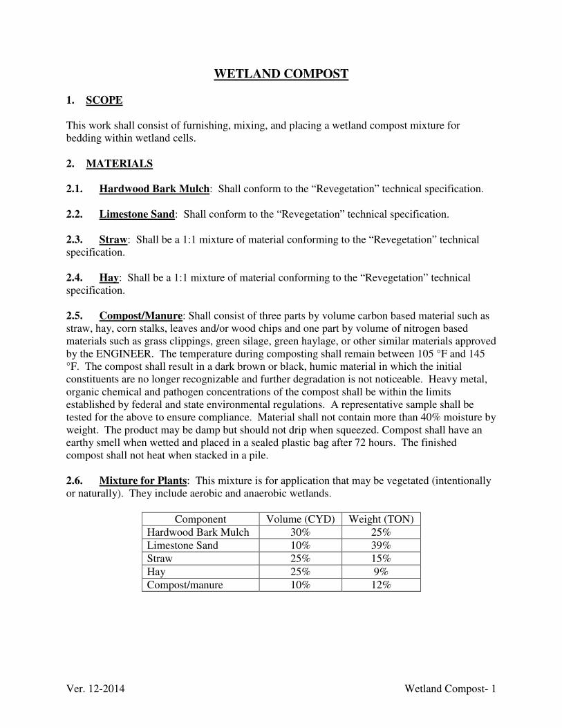
Ver. 12-2014 Wetland Compost- 1
WETLAND COMPOST
1. SCOPE
This work shall consist of furnishing, mixing, and placing a wetland compost mixture for bedding within wetland cells. 2. MATERIALS
2.1. Hardwood Bark Mulch: Shall conform to the “Revegetation” technical specification.
2.2. Limestone Sand: Shall conform to the “Revegetation” technical specification.
2.3. Straw: Shall be a 1:1 mixture of material conforming to the “Revegetation” technical specification. 2.4. Hay: Shall be a 1:1 mixture of material conforming to the “Revegetation” technical specification.
2.5. Compost/Manure: Shall consist of three parts by volume carbon based material such as straw, hay, corn stalks, leaves and/or wood chips and one part by volume of nitrogen based materials such as grass clippings, green silage, green haylage, or other similar materials approved by the ENGINEER. The temperature during composting shall remain between 105 °F and 145 °F. The compost shall result in a dark brown or black, humic material in which the initial constituents are no longer recognizable and further degradation is not noticeable. Heavy metal, organic chemical and pathogen concentrations of the compost shall be within the limits established by federal and state environmental regulations. A representative sample shall be tested for the above to ensure compliance. Material shall not contain more than 40% moisture by weight. The product may be damp but should not drip when squeezed. Compost shall have an earthy smell when wetted and placed in a sealed plastic bag after 72 hours. The finished compost shall not heat when stacked in a pile.
2.6. Mixture for Plants: This mixture is for application that may be vegetated (intentionally or naturally). They include aerobic and anaerobic wetlands.
Component Volume (CYD) Weight (TON)
Hardwood Bark Mulch 30% 25%
Limestone Sand 10% 39%
Straw 25% 15%
Hay 25% 9%
Compost/manure 10% 12%
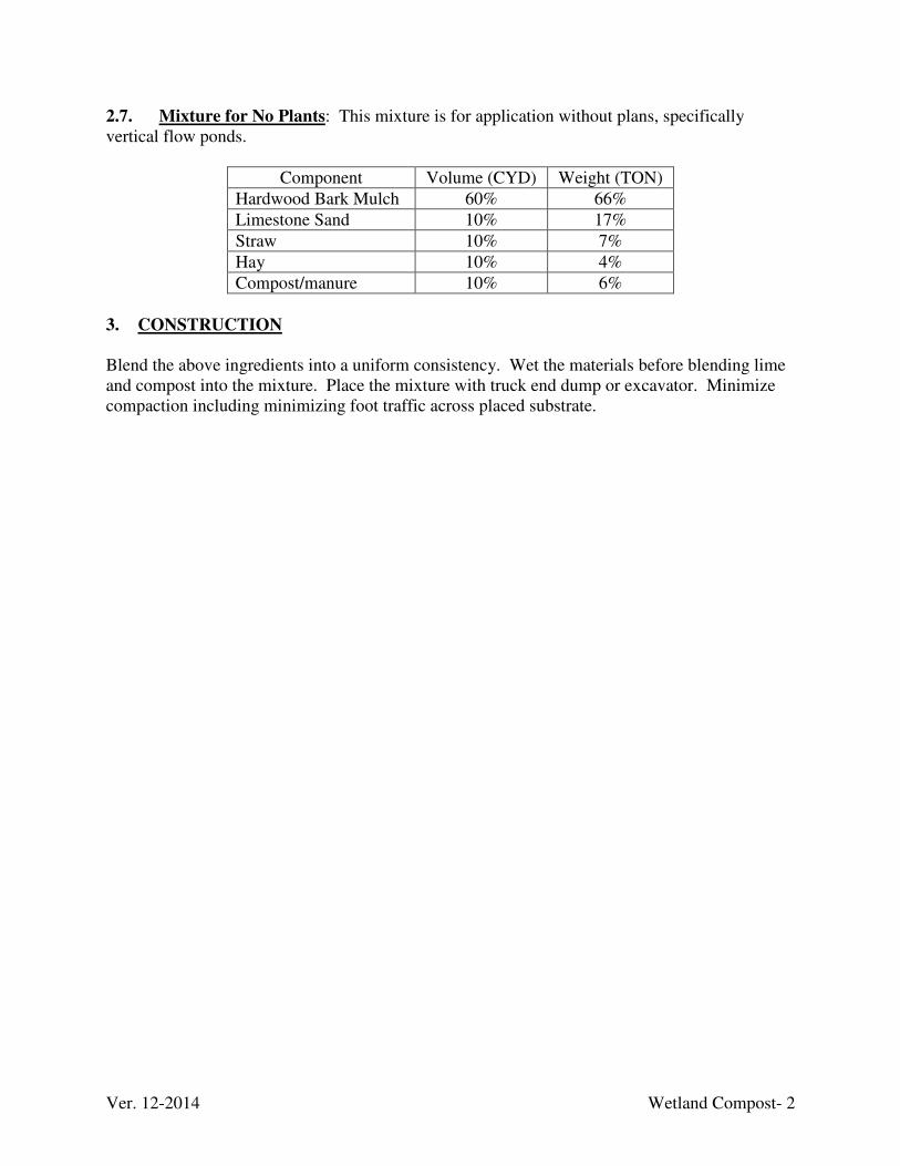
Ver. 12-2014 Wetland Compost- 2
2.7. Mixture for No Plants: This mixture is for application without plans, specifically vertical flow ponds.
Component Volume (CYD) Weight (TON)
Hardwood Bark Mulch 60% 66%
Limestone Sand 10% 17%
Straw 10% 7%
Hay 10% 4%
Compost/manure 10% 6%
3. CONSTRUCTION
Blend the above ingredients into a uniform consistency. Wet the materials before blending lime and compost into the mixture. Place the mixture with truck end dump or excavator. Minimize compaction including minimizing foot traffic across placed substrate.

Ver. 12-2016
APPENDIX
A
SEED MIXES
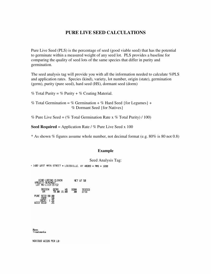
PURE LIVE SEED CALCULATIONS
Pure Live Seed (PLS) is the percentage of seed (good viable seed) that has the potential to germinate within a measured weight of any seed lot. PLS provides a baseline for comparing the quality of seed lots of the same species that differ in purity and germination. The seed analysis tag will provide you with all the information needed to calculate %PLS and application rates. Species (kind), variety, lot number, origin (state), germination (germ), purity (pure seed), hard seed (HS), dormant seed (dorm) % Total Purity = % Purity + % Coating Material. % Total Germination = % Germination + % Hard Seed {for Legumes} +
% Dormant Seed {for Natives} % Pure Live Seed = (% Total Germination Rate x % Total Purity) / 100) Seed Required = Application Rate / % Pure Live Seed x 100 * As shown % figures assume whole number, not decimal format (e.g. 80% is 80 not 0.8)
Example
Seed Analysis Tag:
Ver. 12-2016 Appendix A-1
In this example we have a 50lb bag of Ladino Clover (Seminole variety), that originated from Oregon. The seed was tested on 2/2016 and has 98.00% purity. When calculating purity for legumes you may have to include the coating % as well. To calculate Total Germination you need to add % germination and % Hard seed (legumes) or % Dormant Seed (natives).
% Total Purity= % purity + % coating material
In this instance the % Total Purity = 98.00% purity + 0.00% coating material = 98.00%
% Total Germination= % germination + % Hard seed (Legumes) + % Dormant
Seed (Natives)
% Total Germination = 70.00% germination + 15% hard seed + 0% dormant = 85.00%
% Pure Live Seed = % Total Purity x % Total Germination / 100
% PLS = 98.00% Total Purity x 85.00% Total Germination / 100 = 83.3% This tells you that out of every bulk pound of seed from this lot of Ladino Clover; only 83.3% would be good viable seed. If you purchased a bag of this seed and it weighed 50 pounds, you would only be purchasing 41.65 pounds of good viable seed. To apply this calculation for field uses when inspecting the seed mixing process, we simply divide the Application rate by the % PLS
Seed Required = Application Rate / % Pure Live Seed
Seed Required = 80 lbs/acre PLS Application Rate /83.3% PLS X 100 = 96.04 lbs You would need to mix 96 lbs/acre to achieve the 580 lbs of PLS seed required.
Ver. 12-2016 Appendix A-2
HYDROMULCH & HYDROSEEDING (Major Incidentals)*
The COMMONWEALTH will only pay for the use of a hydroseeder when used to apply hydromulch on project areas specified in the Drawings, Special Conditions, and on all areas where soil material has been removed to bedrock. No seedbed preparation or netting is required on these areas. The equipment, hydromulch, seed, lime, fertilizer, and tack are all incidental to the
bid item. Ag-lime or rock dust meeting the requirements of this section and 100% shall pass through a U.S. Standard # 50 sieve shall be applied at a rate of 1 ton per acre and is not incidental.
RESIDENTIAL SEEDING (Major Incidentals)*
In areas around houses, lime, fertilizer, and seeding rates will vary and additional seedbed preparation work will be required for revegetation of residential areas. Additional seedbed preparation shall be required including hand raking and tilling. Residential Seeding includes seedbed preparation, lime, seed, fertilizer, straw only
mulch and any other material or items necessary to complete the required work.
*For more information about this item refer to the “Revegetation” section of these Technical Specifications.

Ver. 12-2016 Appendix A-3
SEEDING DATES
The following seeding dates will apply to all seed mixtures.
Eastern Zone
START DATE END DATE SEASON
March 1st June 15th Spring
June 16th August 15th Cover Crop Only
August 16th November 15th Fall
November 16th February 28th (29th) Cover Crop Only
Western Zone
START DATE END DATE SEASON
March 1st May 30th Spring
June 1st August 31st Cover Crop Only
September 1st November 15th Fall
December 1st February 28th (29th) Cover Crop Only
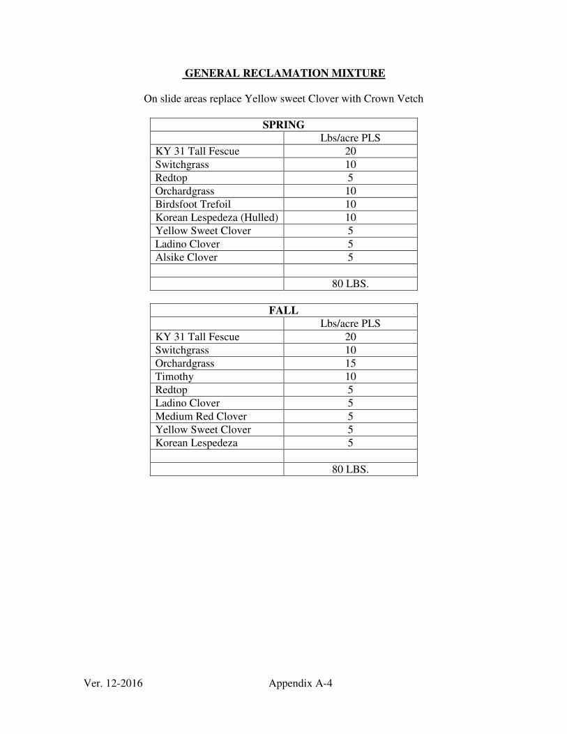
Ver. 12-2016 Appendix A-4
GENERAL RECLAMATION MIXTURE
On slide areas replace Yellow sweet Clover with Crown Vetch
SPRING
Lbs/acre PLS
KY 31 Tall Fescue 20
Switchgrass 10
Redtop 5
Orchardgrass 10
Birdsfoot Trefoil 10
Korean Lespedeza (Hulled) 10
Yellow Sweet Clover 5
Ladino Clover 5
Alsike Clover 5
80 LBS.
FALL
Lbs/acre PLS
KY 31 Tall Fescue 20
Switchgrass 10
Orchardgrass 15
Timothy 10
Redtop 5
Ladino Clover 5
Medium Red Clover 5
Yellow Sweet Clover 5
Korean Lespedeza 5
80 LBS.
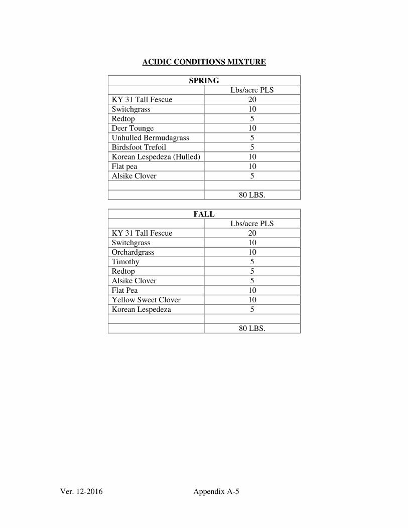
Ver. 12-2016 Appendix A-5
ACIDIC CONDITIONS MIXTURE
SPRING
Lbs/acre PLS
KY 31 Tall Fescue 20
Switchgrass 10
Redtop 5
Deer Tounge 10
Unhulled Bermudagrass 5
Birdsfoot Trefoil 5
Korean Lespedeza (Hulled) 10
Flat pea 10
Alsike Clover 5
80 LBS.
FALL
Lbs/acre PLS
KY 31 Tall Fescue 20
Switchgrass 10
Orchardgrass 10
Timothy 5
Redtop 5
Alsike Clover 5
Flat Pea 10
Yellow Sweet Clover 10
Korean Lespedeza 5
80 LBS.
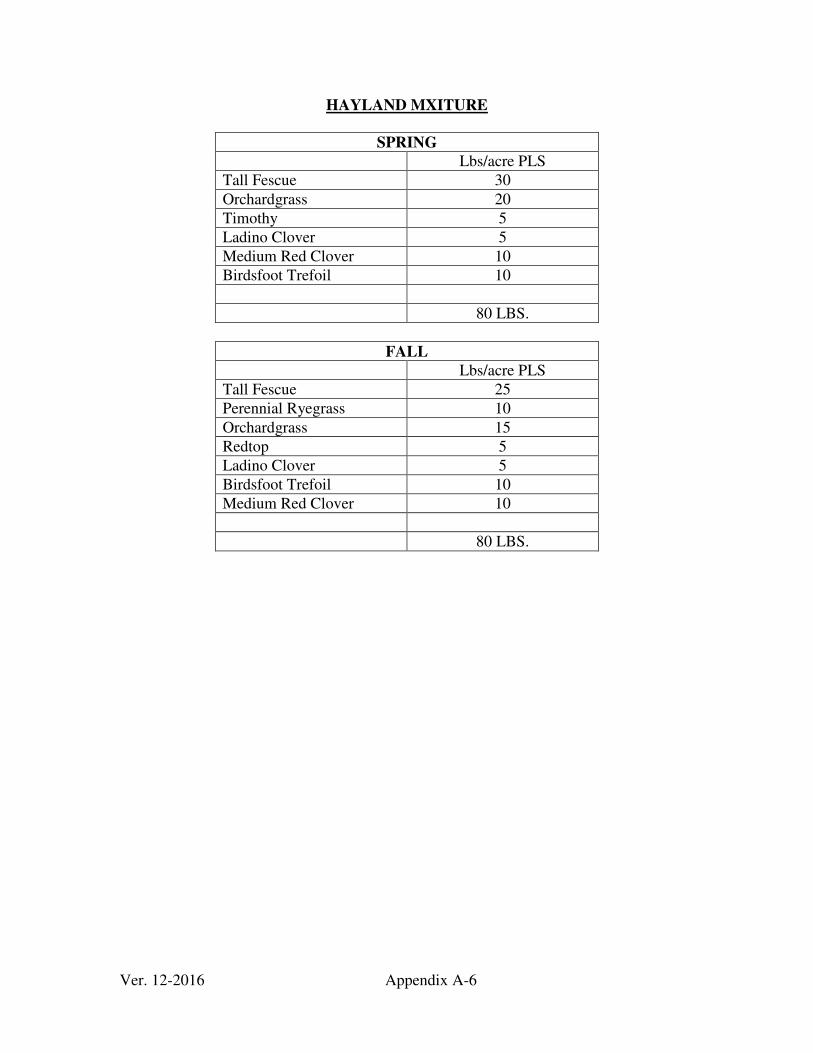
Ver. 12-2016 Appendix A-6
HAYLAND MXITURE
SPRING
Lbs/acre PLS
Tall Fescue 30
Orchardgrass 20
Timothy 5
Ladino Clover 5
Medium Red Clover 10
Birdsfoot Trefoil 10
80 LBS.
FALL
Lbs/acre PLS
Tall Fescue 25
Perennial Ryegrass 10
Orchardgrass 15
Redtop 5
Ladino Clover 5
Birdsfoot Trefoil 10
Medium Red Clover 10
80 LBS.
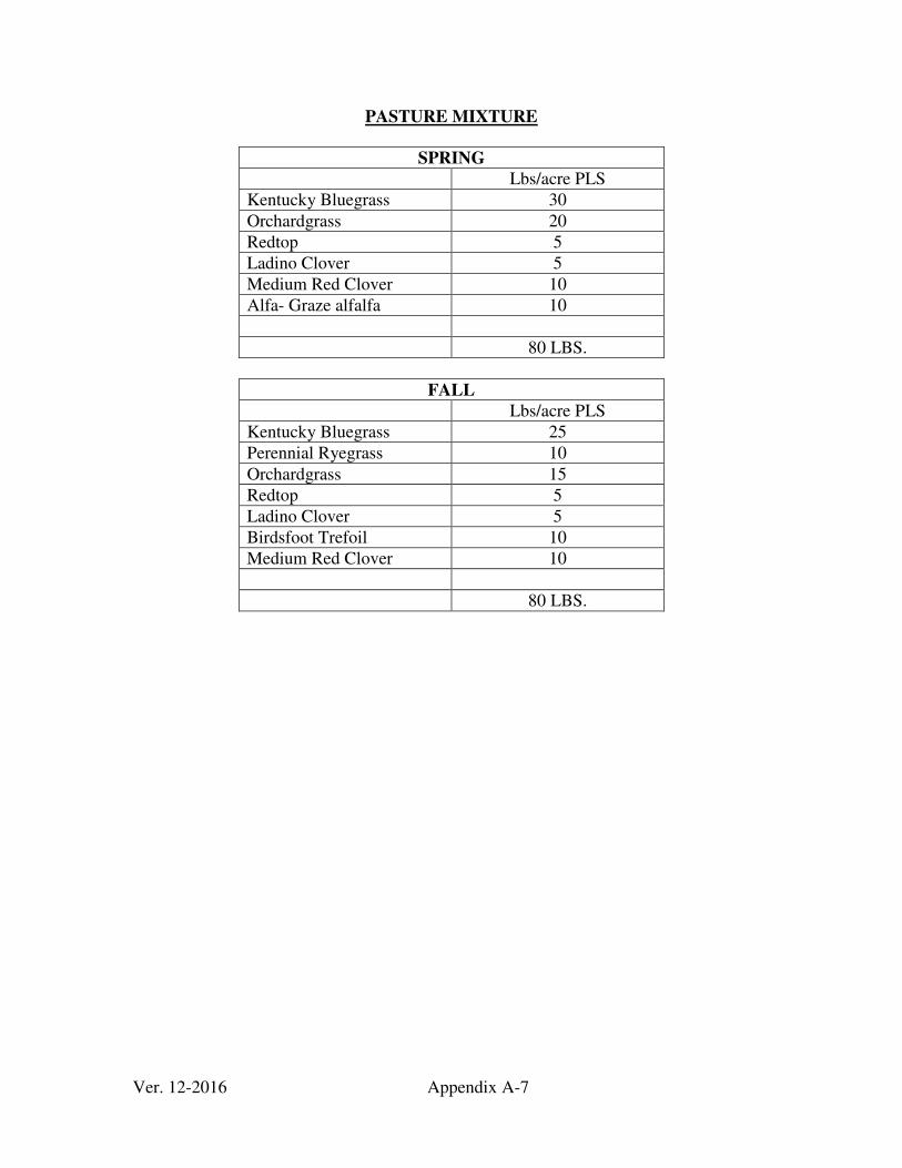
Ver. 12-2016 Appendix A-7
PASTURE MIXTURE
SPRING Lbs/acre PLS
Kentucky Bluegrass 30
Orchardgrass 20
Redtop 5
Ladino Clover 5
Medium Red Clover 10
Alfa- Graze alfalfa 10
80 LBS.
FALL Lbs/acre PLS
Kentucky Bluegrass 25
Perennial Ryegrass 10
Orchardgrass 15
Redtop 5
Ladino Clover 5
Birdsfoot Trefoil 10
Medium Red Clover 10
80 LBS.
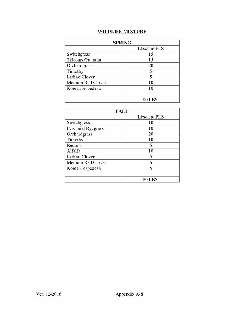
Ver. 12-2016 Appendix A-8
WILDLIFE MIXTURE
SPRING
Lbs/acre PLS
Switchgrass 15
Sideoats Gramma 15
Orchardgrass 20
Timothy 5
Ladino Clover 5
Medium Red Clover 10
Korean lespedeza 10
80 LBS.
FALL
Lbs/acre PLS
Switchgrass 10
Perennial Ryegrass 10
Orchardgrass 20
Timothy 10
Redtop 5
Alfalfa 10
Ladino Clover 5
Medium Red Clover 5
Korean lespedeza 5
80 LBS.

Ver. 12-2016
APPENDIX
B

Ver. 12-2016 Appendix B-1
Erosion and Sediment Control Best Management Practices (BMP) Plan
January 2017
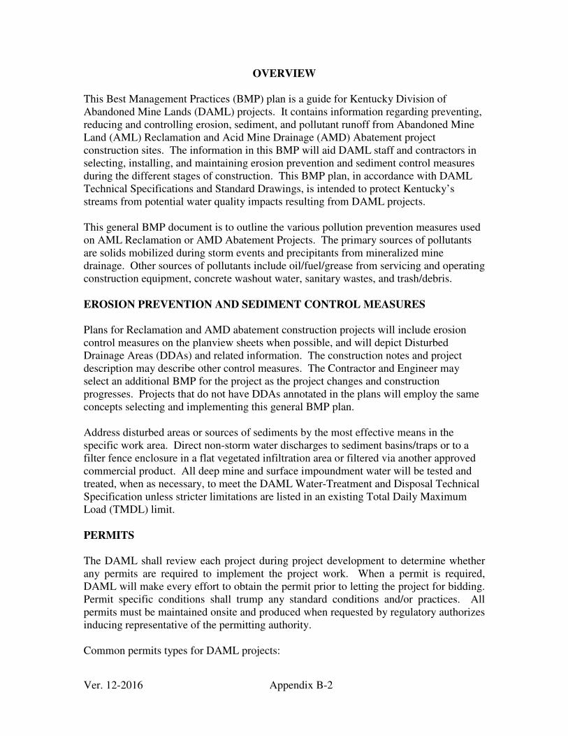
Ver. 12-2016 Appendix B-2
OVERVIEW
This Best Management Practices (BMP) plan is a guide for Kentucky Division of Abandoned Mine Lands (DAML) projects. It contains information regarding preventing, reducing and controlling erosion, sediment, and pollutant runoff from Abandoned Mine Land (AML) Reclamation and Acid Mine Drainage (AMD) Abatement project construction sites. The information in this BMP will aid DAML staff and contractors in selecting, installing, and maintaining erosion prevention and sediment control measures during the different stages of construction. This BMP plan, in accordance with DAML Technical Specifications and Standard Drawings, is intended to protect Kentucky’s streams from potential water quality impacts resulting from DAML projects. This general BMP document is to outline the various pollution prevention measures used on AML Reclamation or AMD Abatement Projects. The primary sources of pollutants are solids mobilized during storm events and precipitants from mineralized mine drainage. Other sources of pollutants include oil/fuel/grease from servicing and operating construction equipment, concrete washout water, sanitary wastes, and trash/debris. EROSION PREVENTION AND SEDIMENT CONTROL MEASURES
Plans for Reclamation and AMD abatement construction projects will include erosion control measures on the planview sheets when possible, and will depict Disturbed Drainage Areas (DDAs) and related information. The construction notes and project description may describe other control measures. The Contractor and Engineer may select an additional BMP for the project as the project changes and construction progresses. Projects that do not have DDAs annotated in the plans will employ the same concepts selecting and implementing this general BMP plan. Address disturbed areas or sources of sediments by the most effective means in the specific work area. Direct non-storm water discharges to sediment basins/traps or to a filter fence enclosure in a flat vegetated infiltration area or filtered via another approved commercial product. All deep mine and surface impoundment water will be tested and treated, when as necessary, to meet the DAML Water-Treatment and Disposal Technical Specification unless stricter limitations are listed in an existing Total Daily Maximum Load (TMDL) limit. PERMITS
The DAML shall review each project during project development to determine whether any permits are required to implement the project work. When a permit is required, DAML will make every effort to obtain the permit prior to letting the project for bidding. Permit specific conditions shall trump any standard conditions and/or practices. All permits must be maintained onsite and produced when requested by regulatory authorizes inducing representative of the permitting authority. Common permits types for DAML projects:

Ver. 12-2016 Appendix B-3
• 401 Water Quality Certification (WQC) o Issued by the KY Division of Water
• 402 KY Pollution Discharge Elimination System (KPDES) o DAML activities are covered under the AML KPDES General Permit
• 404 US Army Corps of Engineers (USACE) o Issued by the US Army Corps of Engineers- Nashville District, Louisville
District, or Huntington District (Depending upon major drainage basin)
• KY Stream Construction (Floodplain) o Issued by the KY Division of Water
• Local Floodplain Permit o Issued by the County/Municipality
• Local Storm Water Construction o Issued by the County/Municipality
A) Field Review Walk-Thru:
The DAML will conduct a project review between the Project Engineer, Construction Branch Personnel, Project Design Technician, and Field Office Staff, to review the construction plans and identify any changes needed prior to letting the project for bidding. The group will evaluate the locations and types of site specific BMP and any other erosion prevention and sediment control measures chosen for incorporation into the final design plans.
B) Pre-Bid Conference
DAML will present the project specific BMP and permit requirements/conditions to the potential contractors during the pre-bid conference meeting.
C) Pre-Construction Conference
Prior to the actual beginning of the project, DAML will hold a pre-construction conference between representatives of the DAML, the Contractor, including any Subcontractors, as well as other interested agencies and parties. Items discussed will include the time and sequence for construction, planned methods of operation, payment, and other relevant questions including any permit requirements and the erosion and sediment control plan.
D) Construction Access
This is the first land-disturbing activity. Construction entrances shall be a minimum of twenty (20) feet wide by fifty (50) feet long, measured from the shoulder of the public road, and consist of No. 2 aggregate over a heavy weight non-woven filter fabric base. As soon as construction begins, stabilize bare areas with gravel and temporary mulch and/or vegetation.
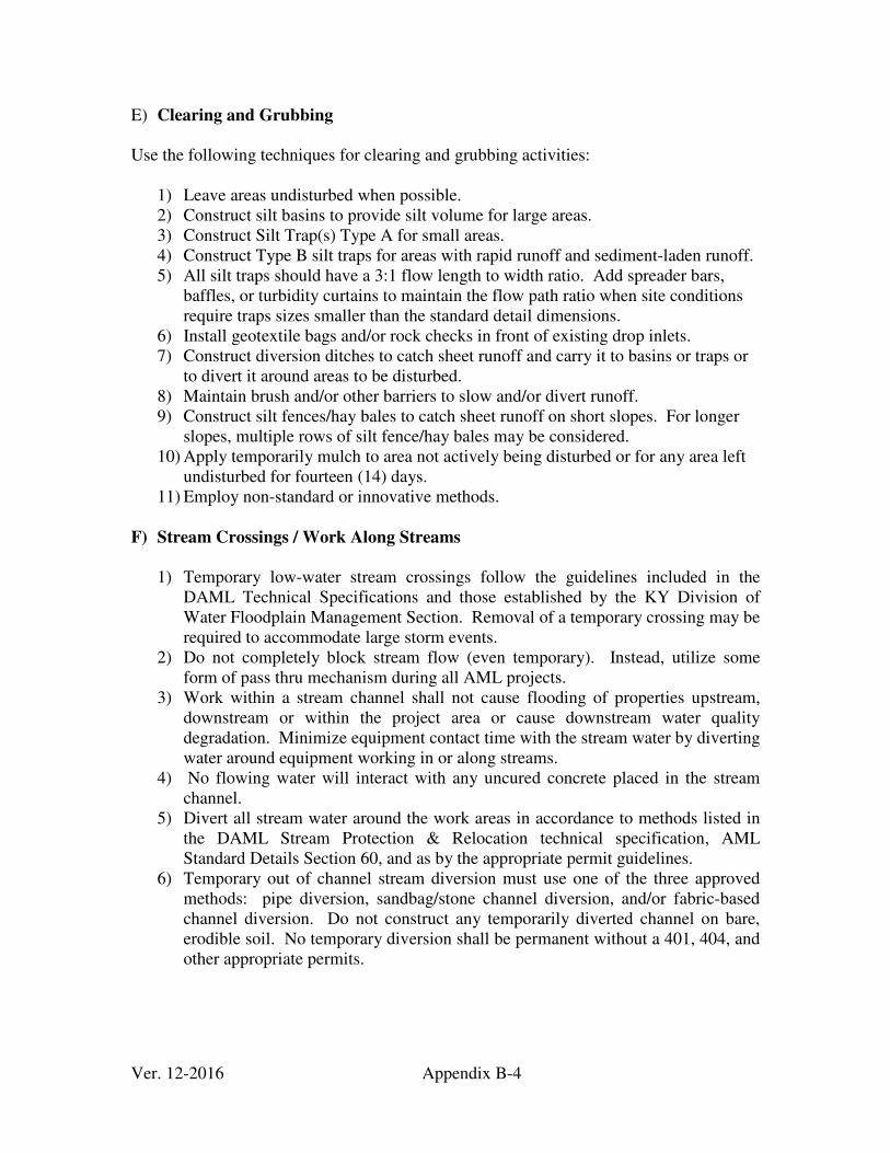
Ver. 12-2016 Appendix B-4
E) Clearing and Grubbing Use the following techniques for clearing and grubbing activities:
1) Leave areas undisturbed when possible. 2) Construct silt basins to provide silt volume for large areas. 3) Construct Silt Trap(s) Type A for small areas. 4) Construct Type B silt traps for areas with rapid runoff and sediment-laden runoff. 5) All silt traps should have a 3:1 flow length to width ratio. Add spreader bars,
baffles, or turbidity curtains to maintain the flow path ratio when site conditions require traps sizes smaller than the standard detail dimensions.
6) Install geotextile bags and/or rock checks in front of existing drop inlets. 7) Construct diversion ditches to catch sheet runoff and carry it to basins or traps or
to divert it around areas to be disturbed. 8) Maintain brush and/or other barriers to slow and/or divert runoff. 9) Construct silt fences/hay bales to catch sheet runoff on short slopes. For longer
slopes, multiple rows of silt fence/hay bales may be considered. 10) Apply temporarily mulch to area not actively being disturbed or for any area left
undisturbed for fourteen (14) days. 11) Employ non-standard or innovative methods.
F) Stream Crossings / Work Along Streams
1) Temporary low-water stream crossings follow the guidelines included in the DAML Technical Specifications and those established by the KY Division of Water Floodplain Management Section. Removal of a temporary crossing may be required to accommodate large storm events.
2) Do not completely block stream flow (even temporary). Instead, utilize some form of pass thru mechanism during all AML projects.
3) Work within a stream channel shall not cause flooding of properties upstream, downstream or within the project area or cause downstream water quality degradation. Minimize equipment contact time with the stream water by diverting water around equipment working in or along streams.
4) No flowing water will interact with any uncured concrete placed in the stream channel.
5) Divert all stream water around the work areas in accordance to methods listed in the DAML Stream Protection & Relocation technical specification, AML Standard Details Section 60, and as by the appropriate permit guidelines.
6) Temporary out of channel stream diversion must use one of the three approved methods: pipe diversion, sandbag/stone channel diversion, and/or fabric-based channel diversion. Do not construct any temporarily diverted channel on bare, erodible soil. No temporary diversion shall be permanent without a 401, 404, and other appropriate permits.
Ver. 12-2016 Appendix B-5
G) Deep Mine and Surface Water Impoundments The DAML Resident Inspector will test the mine water from deep mines and surface impoundments on the project area to determine the pH and total iron content. Treat the water until it meets the DAML Water-Treatment and Disposal Technical Specification or an existing TMDL, whichever is stricter, before release through a silt control structure(s).
Monitoring & Recording
The DAML Inspector will maintain a log of the pH and total iron content results prior to releasing and during each release day. Perform a minimum of two (2) tests downstream each day to ensure the maintenance of water quality during release and is not degrading the receiving stream.
Types of structures/facilities include:
1) Silt Traps Type A (20’L x 5’W x 2’D min dugout) 2) Silt Traps Type B (20’L x 5’W x 2’D min dugout with rock berm) 3) Silt Check - Rock checks with filter fabric core lining installed in channels and in
front of pipes 4) Temporary silt control fence with Class II filter berm 5) Sediment collection bags
H) Cut and Fill and Placement of Drainage Structures
Areas at final grade will be seeded and mulched within five (5) days. Soil stock piles and areas that are not at final grade but where construction will cease for a period of fourteen (14) days or longer, shall receive temporary mulch no later than fourteen (14) days from the last construction activity in that area.
Types of structures/facilities include:
1) Silt Traps Type B (20’L x 5’W x 2’D min dugout with rock berm) 2) Silt Checks - Bags in front of pipes after they are placed 3) Channel lining 4) Erosion control blanket 5) Temporary mulch and/or seeding for areas where construction activities will be
ceased for 14 days or more 6) Non-standard or innovative methods
I) Temporary Shutdown
Items to be completed prior to shutdown include:
1) Clean out behind, repair or replace silt fence and/or hay bales 2) Clean out all silt traps
Ver. 12-2016 Appendix B-6
3) Apply temporary mulch and track into the soil 4) Sow cover crop (weather permitting)
J) Finish Work
1) Establish permanent seeding and protection 2) Remove non-permanent silt checks from ditches and drains if protected with other
BMPs sufficient to control erosion and vegetation is established. 3) Remove non-permanent silt traps and basins. 4) Remove geotextile silt fence. 5) Planting trees and/or shrubs where they are included in the project. 6) Clean out behind, repair, and/or replace bale silt barriers 7) Clean out all permanent silt traps and basins
K) Post-Construction
The Contractor shall assume responsibility for all workmanship and materials for a period of one year from the date of final payment, as directed by the Contract Documents. Any work found to be defective due to failure to comply with the provisions and intent of the Contract Documents shall be corrected at the Contractor's expense. Problems determined not to be created by the landowner or due to the Contractor will be addressed by the DAML for a period of up to three years, pending available funding. OTHER CONTROL MEASURES
L) Solid Materials
No solid materials, including rock and building materials, shall be discharged into waters of the U.S. except as authorized by the Clean Water Act (CWA) Section 401 and Section 404 permits.
M) Waste Materials
Collect and store waste materials that may leach pollutants (paint and paint containers, caulk tubes, oil/grease containers, liquids of any kind, soluble materials, etc.) in appropriate covered waste containers. Remove waste containers from the project site frequently as to not allow wastes to become a source of pollution. Instruct all personnel regarding the correct procedure for waste disposal and dispose of wastes in accordance with appropriate regulations.
N) Hazardous Waste
Manage and dispose of hazardous waste materials in the manner specified by local or state regulation. Notify the Resident Inspector if there are any hazardous wastes generated, and provide a plan for the management and disposal of such materials. Instruct site personnel with regard to proper storage and handling of hazardous wastes
Ver. 12-2016 Appendix B-7
when required and use the practices to reduce the risks associated with all hazardous materials. Keep products in original containers unless they are not re-sealable with the original labels and material safety data sheets (MSDS) will be reviewed and retained. O) Spill Prevention Use good housekeeping and material management practices to reduce the risk of spills or other exposure of materials and substances to the weather and/or runoff. Manufacturers' recommended methods for spill cleanup will be maintained on site and readily available upon request. Make personnel aware of procedures and the location of the information and cleanup supplies. Equipment and materials will include as appropriate, brooms, dust pans, mops, rags, gloves, oil absorbents, sand, sawdust, and plastic and metal trash containers. Clean up all spills immediately after discovery. Keep the spill area well ventilated. Personnel will wear appropriate protective clothing to prevent injury from contract with a hazardous substance. Report spills of toxic or hazardous material to the appropriate state/local agency as required by KRS 224 and applicable federal law. Wastes from spill cleanup will be disposed of in accordance with appropriate regulations. The spill prevention plan will be adjusted, as needed, to prevent spills from reoccurring and improve spill response and cleanup. P) Petroleum Products
Monitor vehicles and equipment fueled and maintained on site for leaks, and receive regular preventative maintenance to reduce the chance of leakage. Protect petroleum products onsite will be stored in tightly sealed, clearly labeled containers from exposure to weather. The CONTRACTOR shall not have a total of over 1,300 gallons of petroleum products on site at any given time. Q) Fertilizers Store fertilizers in a covered area away from water. Transfer the contents of any partially used bag of fertilizer to a sealable plastic bin to avoid spills. Once applied, work into the soil and apply mulch to limit exposure to storm water. R) Concrete Truck Washout
Concrete truck mixers and chutes will not be washed on pavement, near storm drain inlets, or within seventy (75) feet of any ditch, stream, wetland, lake, or sinkhole. Where possible, discharge excess concrete and wash water to areas prepared for pouring new concrete, flat areas to be paved that are away from ditches or drainage system features, or other locations that will not drain off site. Where this approach is not possible, excavate a shallow earthen washbasin away from ditches to receive the wash water.
Ver. 12-2016 Appendix B-8
INSPECTIONS Use inspection and maintenance practices to maintain erosion and sediment controls: 1) The Contractor and DAML Resident Inspector will inspect all erosion prevention
and sediment control measures at least once each week and following any rain of 0.1 inch or more.
2) The DAML Resident Inspector will record the silt control inspections by in their daily report.
3) Silt fences/hay bales will be inspected for bypassing, overtopping, undercutting, depth of sediment, tears, and to ensure attachment to secure posts.
4) Inspect silt traps and basins for depth of sediment, and built-up sediment and clean out when it reaches 50% of the design capacity and at the end of the job.
5) Inspect diversion dikes and berms and promptly repaired any breaches. Repair areas that are eroding or scouring and re-seeded / mulched as needed.
6) Inspect temporary and permanent seeding and mulching for bare spots, washouts, and healthy growth. Repair bare or eroded areas as needed.
7) Inspect all material storage and equipment servicing areas that involve the management of bulk liquids fuels and bulk solids weekly for conditions that represent a release or possible release of pollutants to the environment.
MAINTENANCE Maintain all measures in good working order; initiate corrective actions within twenty-four (24) hours of being reported and completed with five (5) days, address critical failures immediately unless site conditions are too dangerous. Remove Built-up sediment from behind the silt fence/hay bales before it has reached halfway up the height of the fence. ENFORCEMENT
At all times, representatives from DAML and enforcement agencies will have access to the project site. The ENGINEER reserves right to stop work until erosion prevention and sediment control problems are addressed to his/her satisfaction.


![Early Growth of Some Deciduous Tree Species on Abandoned ...1]/Early growth of... · Early Growth of Some Deciduous Tree Species on Abandoned Agricultural Lands in Estonia ... growth](https://img.pdfslide.us/doc/110x75/5c5d599c09d3f2f0498cdfcf/early-growth-of-some-deciduous-tree-species-on-abandoned-1early-growth-of.jpg)