Embed Size (px)
Citation preview
KY-32U
PortableAir ConditionerUser's Manual
- Cooling- Dehumidifying- Fan
TABLE OF CONTENTS
INTRODUCTION ..................................................................................................................... 1
IMPORTANT SAFEGUARDS ................................................................................................... 1
PACKAGE CONTAINS: ............................................................................................................ 1
NAMES OF PARTS ............................................................................................................... 2
INSTALLATION BEFORE USE ................................................................................................ 3
CONTROL PANEL AND LCD DISPLAY .................................................................................... 5
CONTROL PANEL FUNCTIONS ............................................................................................. 6
OPERATION USING CONTROL PANEL .................................................................................... 7
OPERATION USING REMOTE CONTROLLER ........................................................................... 8
CONDENSATE WATER DRAINAGE .......................................................................................... 11
MAINTENANCE ..................................................................................................................... 12
TROU BLESHOOTING ............................................................................................................ 14
TECHNICALSPECIFICATIONS ................................................................................................ 15
DISCLAIMER ........................................................................................................................ 15
CONTACT INFORMATION ...................................................................................................... 15
ELECTRIC PRINCIPLE DRAWING .......................................................................................... 16
WARRANTY ........................................................................................................................ 17
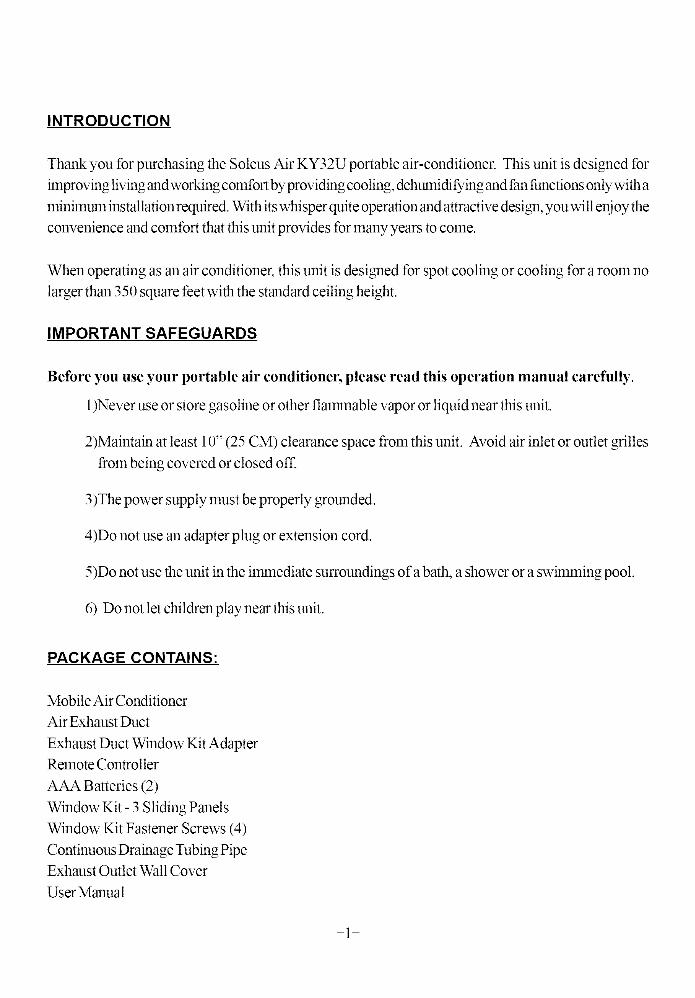
INTRODUCTION
Thank you for purchasing the Soleus Air KY32U portable air-conditioner. This unit is designed for
improving livingandworking comfort byproviding cooling,dehumidi lying andfan functionsonly with a
minimum installation required. With its whisper quite operation and attractive design, you will enjoy the
convenience and comfort that this unit provides for many years to come.
When operating as an air conditioner, this unit is designed for spot cooling or cooling for a room no
larger than 350 square feet with the standard ceiling height.
IMPORTANT SAFEGUARDS
Before you use your portable air conditioner, please read this operation manual carefully.
1)Never use or store gasoline or other flammable vapor or liquid near this unit.
2)Maintain at least 10" (25 CM) clearance space from this unit. Avoid air inlet or outlet grilles
from being covered or closed off.
3)The power supply must be properly grounded.
4)Do not use an adapter plug or extension cord.
5)Do not use the unit in the ilranediate surroundings of a bath, a shower or a swimming pool.
6) Do not let children play near this unit.
PACKAGE CONTAINS:
Mobile Air Conditioner
Air Exhaust Duct
Exhaust Duct Window Kit Adapter
Remote Controller
AAA Batteries (2)
Window Kit - 3 Sliding Panels
Window Kit Fastener Screws (4)
Continuous Drainage Tubing Pipe
Exhaust Outlet Wall Cover
User Manual
-1-
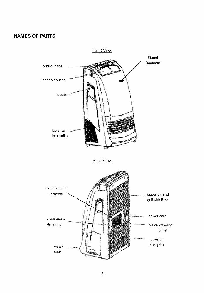
NAMES OF PARTS
control panel
upper air outlet
handle
lower air
inlet grille
Front View
Signal
Receptor
BackView
Exhaust Duct
Terminal
upper air inlet
grill with filter
continuous
drainage
water
tank
power cord
hot air exhaust
outlet
lower air
inlet grille
-2-
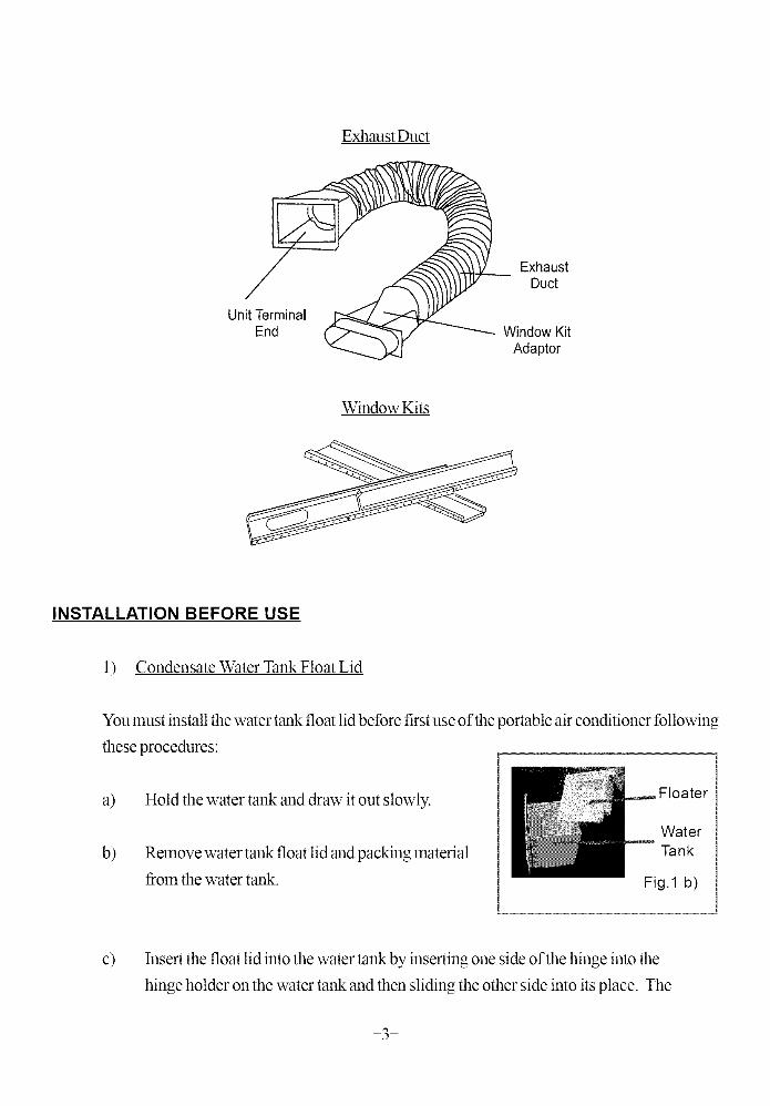
Exhaust Duct
Unit TerminalEnd
ExhaustDu_
Window KitAdaptor
WindowKits
INSTALLATION BEFORE USE
1) Condensate Water Tank Float Lid
You must install the water tank float lid before first use of the portable air conditioner following
these procedures:
a) Hold the water tank and draw it out slowly.
b) Remove water tank float lid and packing material
from the water tank.
Floater
WaterTank
Fig.1 b)
c) Insert the float lid into the water tank by inserting one side of the hinge into the
hinge holder on the water tank and then sliding the other side into its place. The
-3-
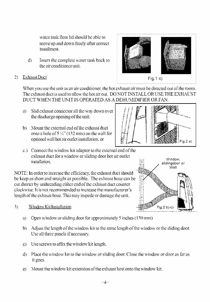
water tank float lid should be able to
move up and down freely after correctinstallment.
d) Insert the complete water tank back tothe air conditioner unit.
2) ExhaustDuct Fig. 1 c)
When you use the unit as an air conditioner, the hot exhaust air must be directed out of the rooln.The exhaust duct is used to allow the hot air out. DO NOT 1NSTALL ORUSE THE EXHAUST
DUCT WHEN THE UNIT IS OPERATED AS A DEHUMIDIFIER OR FAN.
a) Slid exhaust connector all the way down over
the discharge opening of the unit.
b) Mount the external end of the exhaust duct
onto a hole of 5 */4"(13 2 lnln) on the wall for
optional wall hot air outlet installation, or
c.) Connect the window kit adaptor to the external end of the
exhaust duct for a window or sliding door hot air outletinstallation.
NOTE: In order to increase the efficiency, the exhaust duct should
be keep as short and straight as possible. The exhaust hose can be
cut shorter by unthreading either end of the exhaust duct counterclockwise. It is not recommended to increase the manufacturer's
length of the exhaust hose. This may impede or damage the unit.
Fig.2 a)
Window,slidingdoor or
Wall
3) Window Kit Installation Fig.2 b)-c)
a) Open window or sliding door for approximately 5 inches (130 ram)
b) Adjust the length of the window kit to the same length of the window or the sliding door.Use all three panels if necessary.
c) Use screws to affix the window kit length.
d) Place the window kit to the window or sliding door. Close the window or door as Parasit goes.
e) Mount the window kit extension of the exhaust host onto the window kit.
-4-
t) Use screws on the window kit extension if necessary.
NOTE: When using the window kit on a window or sliding door it will cause the window or slidingdoornot to be properly closed and locked. Additional security measurements should be taken.
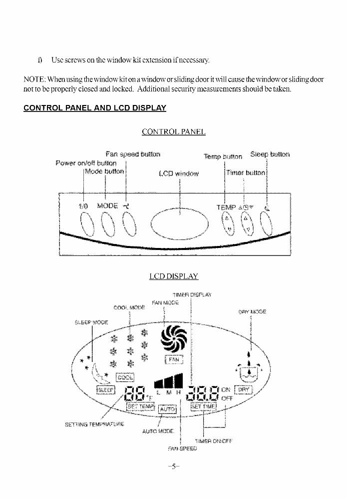
CONTROL PANEL AND LCD DISPLAY
CONTROL PANEL
Fan spef>d _ue¢{onPow÷r on!off bu{_on
MODE
LCD DISPLAY
-5-
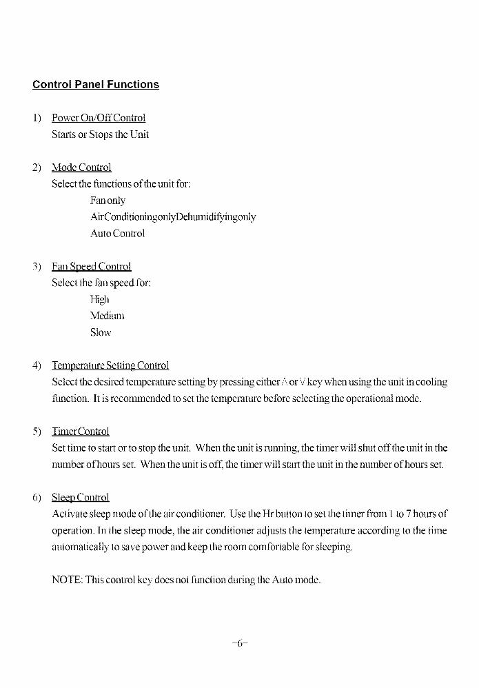
Control Panel Functions
1) Power On/Off Control
Starts or Stops the Unit
2) Mode Control
Select the functions of the unit for:
Fanonly
Air ConditioningonlyDehumidifyingonly
Auto Control
3) Fan Speed Control
Select the Pan speed for:
HighMedium
Slow
4) Temperature Setting Control
Select the desired temperature setting by pressing either ?\or _/key when using the unit in cooling
function. It is recommended to set the temperature before selecting the operational mode.
5) Timer Control
Set time to start or to stop the unit. When the unit is running, the timer will shut offthe unit in the
number of hours set. When the unit is off, the timer will start the unit in the number of hours set.
6) Sleep Control
Activate sleep mode of the air conditioner. Use the Hr button to set the timer from 1 to 7 hours of
operation. In the sleep mode, the air conditioner adjusts the temperature according to the time
automatically to save power and keep the room comfortable for sleeping.
NOTE: This control key does not function during the Auto mode.
-6-
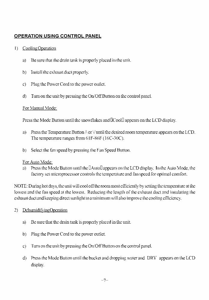
OPERATION USING CONTROL PANEL
1) Cooling Operation
a) Be sure that the drain tank is properly placed in the unit.
b) Install the exhaust duct properly.
c) Plug the Power Cord to the power outlet.
d) Turn on the unit bypressing the On!OffButton on the control panel.
For Manual Mode:
Press the Mode Button until the snowflakes and _Cool_ appears on the LCD display.
a) Press the Temperature Button ?\or _/until the desired room temperature appears on the LCD.
The temperature ranges from 61F-86F (16C-30C).
b) Select the fan speed by pressing the Fan Speed Button.
For Auto Mode:
a) Press the Mode Button until the DAutoD appears on the LCD display. In the Auto Mode, the
factory set microprocessor controls the temperature and fan speed for optimal comfol_.
NOTE: During hot days, the unit will cool offthe room most efficiently by setting the temperature at the
lowest and the fan speed at the lowest. Reducing the length of the exhaust duct and insulating the
exhaust duct and keeping direct sunlight to a minimum will also improve the cooling efficiency.
2) Dehumidify ingOperation
a) Be sure that the drain tank is properly placed in the unit.
b) Plug the Power Cord to the power outlet.
c) Turn on the unit by pressing the On!OffButton on the control panel.
d) Press the Mode Button until the bucket and dropping water and DRY appears on the LCD
display.
-7-
NOTE: Do not use the exhaust duct when the unit is running at dehumidifying model. You must remove
the exhaust duct from the unit. When the unit is running at dehumidifying mode, the Panspeed cannot be
adjusted.
Keep the windows and the doors closed to aid the effectiveness of the unit in removing the moisture
from the room.
3) Fan Operation
a) Plug the Power Cord to the power outlet.
b) Turn on the unit bypressing the On!OffButton on the control panel.
c) Press the Mode Button until DFANDappears on the LCD display.
d) Select the Pan speed by pressing the Fan Speed Button.
NOTE: When the unit is running on Pan mode, the exhaust duct is inoperative and is not required.
OPERATION USING REMOTE CONTROLLER
The remote controller provided with the unit may operate this portable air conditioner. The remote
controller uses two - AAA batteries (provided). Install the batteries before using the remote controller.
NOTE: The information displayed on the LCD of the remote controller will only be transmitted to the
air conditioner when the On!Off, Transmit, Sleep or Auto buttons (transmitting buttons) are pressed.
Any changes made to the LCD display will bereversed to the previous setting if none of the transmitting
buttons is pressed within 15 seconds after the changes are made.
NOTE: When the remote controller is off, the LCD only displays the current time.
-8-
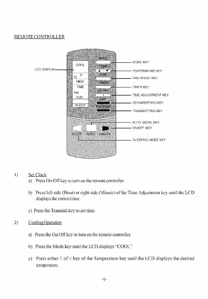
REMOTE CONTROLLER
LCD DISPLAY
MODE KEY
TEMPERATURE KEY
FAN SPEED KEY
TIMER KEY
TIME ADJUSTMENT KEY
DEHUMIDIFYING KEY
TRANSMITTING KEY
AUTO MODE KEY
ON/OFF KEY
SLEEPING MODE KEY
l)
2)
Set Clock
a) Press On!Off key to turn on the remote controller
b) Press left side (Hour) or right side (Minute) of the Time Adjustment key until the LCD
displays the correct time.
c) Press the Transmit key to set tilne.
Cooling Operation
a) Press the On/Offkey to turn on the remote controller
b) Press the Mode key until the LCD displays "COOL"
c) Press either/\ of\/key of the Telnperamre key until the LCD displays the desired
temperature.
-9-
d) Press the Fan Speed key until the LCD displays the desired fan speed.
e) Press the Transmit key.
NOTE: When pressing the Mode Key, the LCD displays "COOL", "FAN" AND "HEAT". This
KY-32U unit does not have a heating function.
3) DehumidifyingOperation
a) Press the On!Offkey to turn on the remote controller
b) Press Dehumidifying key. "DRY" will appear on the LCD display.
c) Press the Transmit key.
4) Fan Operation
a) Press the On!Offkey to turn on the remote controller
b) Press the Mode key unit "FAN" appears on the LCD display.
c) Press the Fan Speed key until the LCD displays the desired tan speed.
d) Press the Transmit key.
5) Auto Mode
a) Press the On!Offkey to turn on the remote controller
b) Press the Auto key. "AUTO" will appears on the LCD display.
Thner6)
a) Press the On!Offkey to turn on the remote controller
b) Press the Timer key. "TIMER" will appear on the LCD display.
c) Press the Time Adjustment key until the LCD displays the desired number of hours for theoperation.
d) Press the Transmit key.
-10-
7) Sleep Mode
a) Press the On!Offkey to turn on the remote controller.
b) Press the Sleep key. "Sleep" will appear on the LCD display.
c) Press either/\ of V key of the Temperature key until the LCD displays the desired
temperature.
d) Press the Fan Speed keyuntil the LCD displays the desired Pan speed.
e) Press Timer and Time Adjustment keys until the LCD displays the desired operation hours.
f) Press the Transmit key.
CONDENSATE WATER DRAINAGE
1) Internal Water Tank
When operating in cooling or dehumidifying mode, the condensate water will drain into the internal
water tank. Depending o17the surrounding humidity, the unit can continuously operate for 2 to
12 hours before the internal water tank is full. When the internal water tank gets full, the LCD
window shows error code "E4" and a beep alarm will sound eight times for 15 seconds. The
compressor stops running and the Panwill continue to mn in the set speed for three minutes before
the entire unit automatically shuts off.
When the water tank is full, take out the entire water tank slowly and discard the water inside the
tank, place it back to its original position. You will then be able to turn on the unit again.
If you want to take out the internal tank before it is full of water, please stop the unit first. Wait for
3 minutes before taking out the water tank to prevent the condensate water from discharging into
theunit.
NOTE: Do not take out the water tank when the unit is running on either cooling or dehumidifying
mode or the alarm will sound and the compressor stops. The mode will automatically change to FAN
mode and the compressor will require approximately 3 minutes to restart to the cooling/dehumidifying
cycle.
2) Continuous Drainage
The unit can operate on continuous drainage mode. When the unit is operating on continuous drainage
-11-
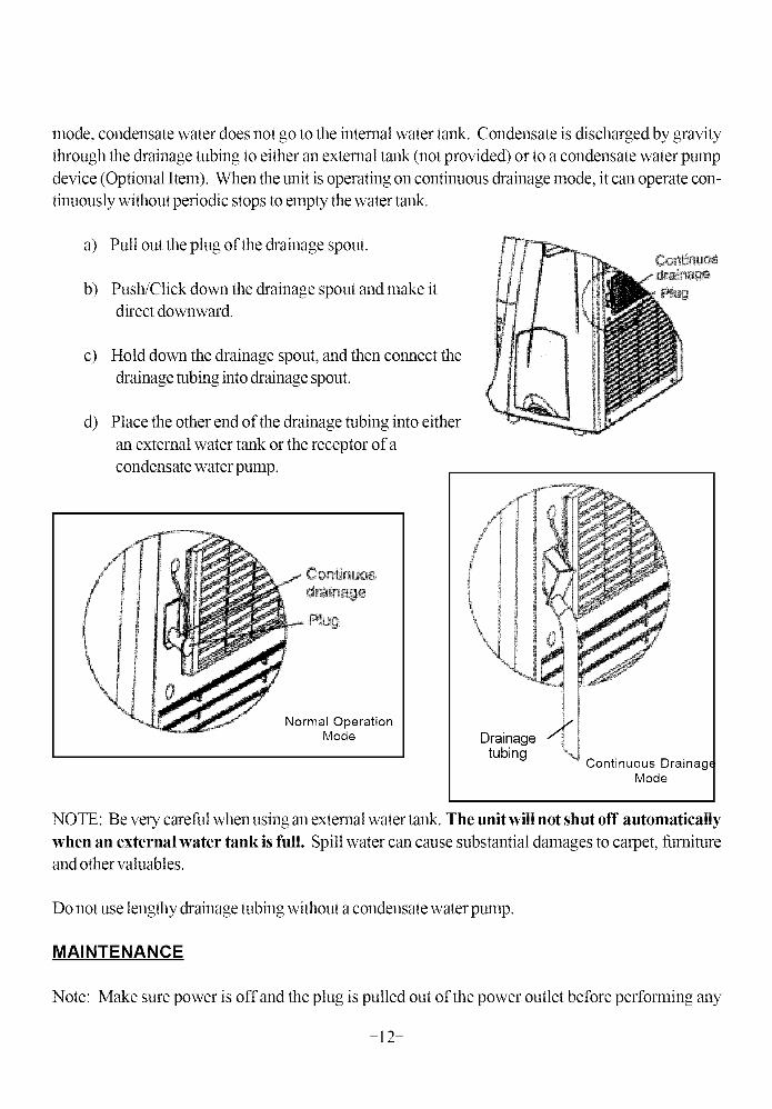
mode, condensate water does not go to the internal water tank. Condensate is discharged by gravity
through the drainage tubing to either an external tank (not provided) or to a condensate water pump
device (Optional Item). When the unit is operating on continuous drainage mode, it can operate con-
tinuously without periodic stops to empty the water tank.
a) Pull out the plug of the drainage spout.
b) Push/Click down the drainage spout and make it
direct downward.
c)
d)
Hold down the drainage spout, and then connect the
drainage tubing into drainage spout.
Place the other end of the drainage robing into either
an external water tank or the receptor of a
condensate water pump.
Normal OperationMode Drainage
tubingSontinuous Drainag,
Mode
NOTE: Be very careful when using an external water tank. The unit will not shut off automatically
when an external water tank is full. Spill water can cause substantial damages to carpet, furniture
and other valuables.
Do not use lengthy drainage robing without a condensate water pump.
MAINTENANCE
Note: Make sure power is off and the plug is pulled out of the power outlet before performing any
-12-
maintenance activities.
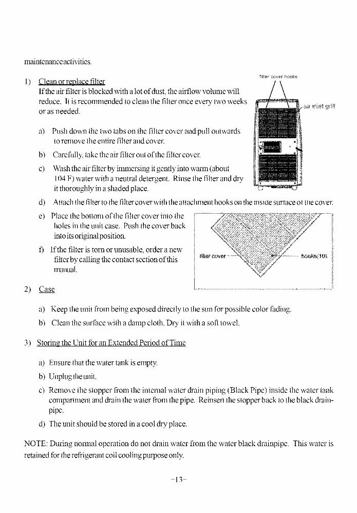
1) Clean or replace filter
If the air filter is blocked with a lot of dust, the airflow volume will
reduce. It is recommended to clean the filter once every two weeksor as needed.
filter cover hooks
a) Push down the two tabs on the filter cover and pull outwardsto remove the entire filter and cover.
b) Carefully, take the air filter out of the filter cover.
c) Wash the air filter by immersing it gentlyinto warm (about
104 F) water with a neutral detergent. Rinse the filter and dry
it thoroughly in a shaded place.
d) Attach the filter to the filter cover with the attachlnent hooks on the msloe surtace ot me cover.
e) Place the bottom of the filter cover into theholes in the unit case. Push the cover back
into its original position.
f) If the filter is torn or unusable, order a new
filter by calling the contact section of thisll3anual.
2) Case
,2 ,gh> N
; ,or! s _ ,,/@/,_4 •,
h
a) Keep the unit from being exposed directly to the sun for possible color fading.
b) Clean the surface with a damp cloth. Dry it with a soft towel.
3) Storing the Unit for an Extended Period of Time
a) Ensure that the water tank is empty.
b) Unplug theunit.
c) Remove the stopper from the internal water drain piping (Black Pipe) inside the water tank
compartment and drain the water from the pipe. Reinsel_ the stopper back to the black drain-
pipe.
d) The unit should be stored in a cool dry place.
NOTE: During normal operation do not drain water from the water black drainpipe. This water is
retained for the refrigerant coil cooling purpose only.
-13-
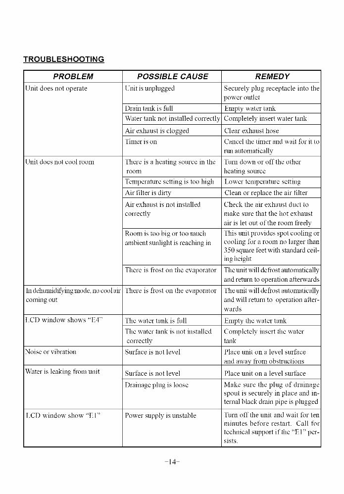
TROUBLESHOOTING
PROBLEM
Unit does not operate
Unit does not cool room
In dehumidifying mode, no cool air
coming out
LCD window shows "E4"
Noise or vibration
Water is leaking from unit
LCD window show "E 1"
POSSIBLE CAUSE
Unit is unplugged
Drain tank is full
Water tank not installed correctly
Air exhaust is clogged
Timer is on
There is a heating source in the
room
Temperature setting is too high
Air filter is dirty
Air exhaust is not installed
correctly
Room is too big or too much
ambient sunlight is reaching in
There is frost on the evaporator
There is frost on the evaporator
The water tank is full
The water tank is not installed
correctly
Surt:ace is not level
Surt:ace is not level
Drainage plug is loose
Power supply is unstable
REMED Y
Securely plug receptacle into the
power outlet
Empty water tank
Completely insert water tank
Clear exhaust hose
Cancel the timer and wait for it to
run automatically
Turn down or off the other
heating source
Lower temperature setting
Clean or replace the air filter
Check the air exhaust duct to
make sure that the hot exhaust
air is let out of the room freely
This unit provides spot cooling or
cooling for a room no larger than
350 square feet with standard ceil-
ing height
The unit will defrost automatically
and return to operation afterwards
The unit will defrost automatically
and will return to operation after-wards
Empty the water tank
Completely insert the water
tank
Place unit on a level surt:ace
and away from obstructions
Place unit on a level surt:ace
Make sure the plug of drainage
spout is securely in place and in-
ternal black drain pipe is plugged
Turn off the unit and wait for ten
minutes betk_re restart. Call for
technical support if the "E 1" per-sists.
-14-
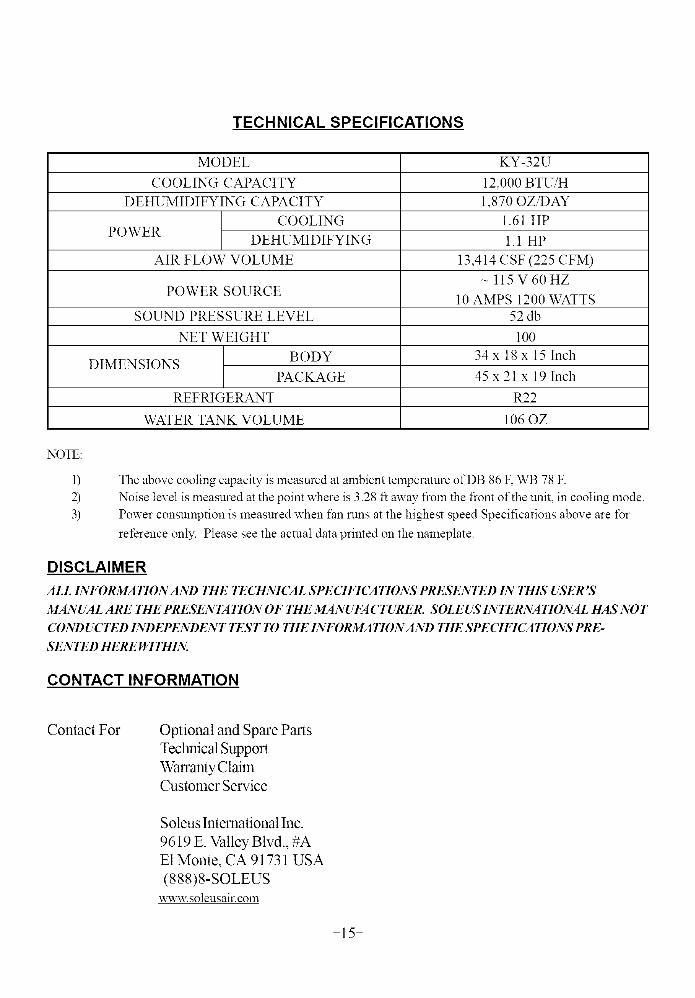
TECHNICAL SPECIFICATIONS
MODEL
COOLING CAPACITY
DEHUMIDIFYING CAPACITY
COOLINGPOWER
DEHUMIDIFYING
AIR FLOW VOLUME
POWER SOURCE
SOUND PRESSURE LEVEL
NET WEIGHT
BODYDIMENSIONS
PACKAGE
REFRIGERANT
WATER TANK VOLUME
KY-32U
12,000 BTU/H
1,870 OZ/DAY
1.61 HP
1.1 HP
13,414 CSF (225 CFM)
ll5V60HZ
10 AMPS 1200 WATTS
52db
100
34 x 18 x 15 Inch
45 x 21 x 19 Inch
R22
106 OZ
NOTE:
1)2)3)
The above cooling capacity is measured at ambient telnperature of DB 86 F, WB 78 F.
Noise level is measured at the point where is 3.28 ft away from the front of the unit, in cooling mode.
Power consumption is measured when fan runs at the highest speed Specifications above are t\_r
reference only. Please see the actual data printed on the nameplate.
DISCLAIMER
ALL INFORMATION AND THE TECHNICAL SPECIFICATIONS PRESENTED IN THIS USER "_
MANUAL ARE THE PRESENTATION OF THE MANUFACTURER. SOLEUS INTERNATIONAL HAS NOT
CONDUCTED INDEPENDENT TEST TO THE INFORMATIONAND THE SPECIFICATIONS PRE-
SENTED HERE WITHIN.
CONTACT INFORMATION
Contact For Optional and Spare PartsTechnical Support
Warranty ClaimCustomer Service
Soleus International Inc.
9619 E. Valley Blvd., #A
E1 Monte, CA 91731 USA
(888)8-SOLEUS
,a-ww.soleusair.com
-15-
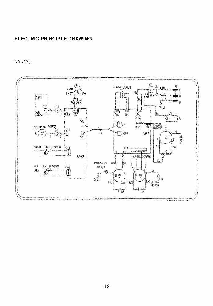
ELECTRIC PRINCIPLE DRAWING
KY-32U
-16-
WARRANTY
ONE YEAR LIMITED WARRANTY
Soleus International Inc. warrants the accompanying Soleus Air KY-3 2U Mobile Air Conditioner to
be free of defects in material and workmanship for the applications specified in its operation instruction
for a period of ONE (1) year from the date of original retail purchase in the United States or Canada.
If the air conditioner exhibits a defect in normal use, Soleus International Inc. will, at its option, either
repair or replace it, free of charge within a reasonable time after the air conditioner is returned during
the warranty period.
As a condition to any warranty service obligation, the consumer must present this Warranty Certificate
along with a copy of the original purchase invoice.
THIS WARRANTY DOES NOT COVER:
1) Damage, accidental or other wise, to the air conditioner while in the possession of a consumernot caused by a defect in material or workmanship;
2) Damage caused by consumer misuse, tampering, or failure to follow the care and special han-
dling provisions in the instructions.
3) Damage to the finish of the case, or other appearance parts caused by wear.
4) Filter.
5) Damage cansed by repairs or alterations ofthe air conditioner by anyone other than anthorized
by Soleus International Inc..
6) Freight and Insurance cost for the warranty service.
ALL IMPLIED WARRANTIES, INCLUI)ING ANY IMPLIED WARRANTY OF MERCHANTABILITY ARE LIM-
ITED TO ONE-YEAR DURATION OF THIS EXPRESS LIMITED WARRANTYSOLEUS INTERNATIONAL INC.
DISCLAIMS ANY LIABILITY FOR CONSEQUENTIAL OR INCIDENTAL DAMAGES AND INNO EVENT SHALLSOLEUS INTERNATIONAL 1NC.'S LIABILITY EXCEED THE RETAIL VALUE OF THE AIR CONDITIONER FOR
BREACH OF ANY WRITTEN OR IMPLIED WARRANTY WITH RESPECT TO THIS AIR CONDITIONER
-17-
LCDI POWER CORD AND PLUG
This air conditioner is equipped with an LCDI (Leakage Current Detection and Interruption) power cord and plug
as required by US National Electric Code 440.65. This cord consists of a length of shielded flexible cord with no
termination on the load side and a LCDI attachment plug on the line side.
The LCDI power cord and plug will remove the supply source via electrical disconnect (circuit trip) if the nominal
current leakage between the cord shield and either load conductor exceeds a predetermined value. The cord will
remain de-energized until the devise has been manually reset. This is intended to reduce the risk of a fire in the
power cord or combustible materials nearby. The cord shields are not grounded and they must be considered a
shock hazards if exposed. The cord shield must not be connected to around or to any exposed metal.
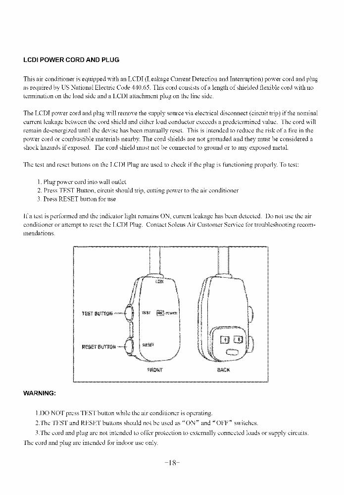
The test and reset buttons on the LCDI Plug are used to check if the plug is functioning properly. To test:
1. Plug power cord into wall outlet
2. Press TEST Button, circuit should trip, cutting power to the air conditioner3. Press RESET button for use
Ifa test is performed and the indicator light remains ON, current leakage has been detected. Do not use the air
conditioner or attempt to reset the LCDI Plug. Contact Soteus Air Customer Service for troubleshooting recom-mendations.
J
J
_T _¢K
WARNING:
1.DO NOT press TEST button while the air conditioner is operating.
2.The TEST and RESET buttons should not be used as "ON" and "OFF" switches.
3.The cord and plug are not intended to offer protection to externally connected loads or supply circuits.
The cord and plug are intended for indoor use only.
-18-