Embed Size (px)
Citation preview
KW800KW800E
KW800_E UK p01-12 16-01-2001, 13:111

Congratulations!On the purchase of yourBlack & Decker router.To ensure the best results from your routerplease read these safety and usageinstructions carefully.
If you have any questions or queries afterreading this user manual please do nothesitate to call our Service and InformationCentre, whose number you will find towardsthe back of this user manual, or one of ourAuthorised Repair Agents. A list of theseAgents and further information is available onthe Internet at www.2helpU.com.
KW800_E UK p01-12 16-01-2001, 13:112
ContentsPage 4 Safety instructions
Double insulation
Page 5 Electrical safetyMains plug replacementExtension cablesUnwanted tools and the environmentThe Black & Decker guaranteeAfter sales service for your Black & Decker product
Page 6 Our after sales service policyAccessoriesTechnical dataFeaturesOperating your router
Page 7 Fitting the router bitAdjusting the depth of cutUsing a piece of woodUsing the scale
Page 8 Fine adjustment with the triple depth stopFitting the edge guideAlternative guide methodFitting the vacuum adaptorFitting the template guideElectronic speed regulationUsing the distance piece
Page 9 Using the centring pinUsing the copy followerRouter bitsHandy hintsTool careEC declaration of conformity
Black & Decker phone numbers and addresses
Guarantee card
KW800_E UK p01-12 16-01-2001, 13:113
4
SAFETY INSTRUCTIONSWarning! When using electric tools, the followingbasic safety precautions should always be taken toreduce the risk of fire, electric shock and personalinjury. Read all these instructions before attempting tooperate the product and save this booklet.
For safe operation:• Keep the work area clean. Cluttered areas and
benches invite injuries.• Consider the work area environment. Do not expose
the power tool to rain and do not use in damp or wetlocations. Keep the work area well lit. Do not usethe power tool where there is a risk to cause fireor explosion.
• Guard against electric shock. Avoid body contact,where possible, with earthed or grounded surfaces(e.g. pipes, radiators, ranges and refrigerators).
• Keep children away. Do not let visitors touch thetool or extension cord. All visitors should be keptaway from the work area.
• Store idle tools. When not in use, tools should bestored in a dry, high or locked place, out of reachof children.
• Do not force the tool. It will do the job better andmore safely at the rate for which it was intended.
• Use the right tool. Do not force small tools orattachments to do the job of a heavy duty tool.Do not use the tool for purposes not intended; forexample, do not use a circular saw to cut treelimbs or logs.
• Dress properly. Do not wear loose clothing orjewellery as they can be caught in moving parts.Rubber gloves and non-skid footwear arerecommended when working outdoors. Wearprotective hair covering to contain long hair.
• Use safety glasses. Use a face or dust mask as well,if the operation is dusty or if the tool is being used inenclosed spaces.
• Connecting dust extraction equipment. If devicesare provided for the connection of dust extractionand collection ensure these are connected andproperly used, especially in confined areas.
• Do not abuse the cord. Never carry the tool by itscord or yank it to disconnect it from the socket. Keepthe cord away from heat, oil and sharp edges.
• Secure the work. Use clamps or a vice to hold thework. It is safer than using a hand and it frees bothhands to operate the tool.
• Do not overreach. Keep proper footing and balance atall times.
• Maintain the tool with care. Keep a cutting toolsharp and clean for better and safer performance.Follow the instructions for lubricating and changingaccessories. Inspect the tools cord periodically and,if damaged, have repaired by an authorised servicefacility. Inspect the extension cord periodically andreplace if damaged. Keep the handles dry, clean andfree from oil and grease.
• Disconnect the tool when not in use, beforeservicing and when changing accessories such asblades, bits and cutters.
• Remove adjusting keys and wrenches. Form thehabit of checking to see that keys and adjustingwrenches are removed from the tool and replaced inthe storage area before switching on.
• Avoid unintentional starting. Do not carry aplugged-in tool with a finger on the switch.Ensure the switch is off when plugging in.
• Use an outdoor extension cord. When a tool is usedoutdoors, only use an extension cord intended foroutdoor use and so marked.
• Stay alert. Watch what you are doing, use commonsense and do not operate the tool when tired.
• Check damaged parts. Before further use of the tool,a guard or other part that is damaged should becarefully checked to determine whether it willoperate properly and perform its intended function.Check for alignment of moving parts, free running ofmoving parts, breakage of parts, mounting and anyother conditions that may affect its operation.A guard or other part that is damaged should beproperly repaired or replaced by an authorisedservice centre unless otherwise indicated in theproduct booklet. Have defective switches replacedby an authorised service agent. Do not use the tool ifthe switch does not turn it on and off.
• Warning! The use of any accessory or attachment,other than recommended in the product booklet,may present a risk of personal injury.
• Have the tool repaired by a qualified person. Theelectrical tool is in accordance with the relevantsafety requirements. Repairs should only be carriedout by qualified persons using original spare parts,otherwise, this may result in considerable danger tothe user.
Save these instructions!
DOUBLE INSULATIONThe tool is double insulated. This means that allthe external metal parts are electrically insulatedfrom the mains power supply. This is done by
Router user manual
KW800_E UK p01-12 16-01-2001, 13:114
5
placing insulation barriers between theelectrical and mechanical components making itunnecessary for the tool to be earthed.Note: Double insulation does not take the placeof normal safety precautions when operating thetool. The insulation system is for added protectionagainst injury resulting from a possible electricalinsulation failure within the tool.
ELECTRICAL SAFETYBe sure the supply is the same as the voltage given onthe rating plate. The tool is fitted with a two-core cableand plug.
MAINS PLUG REPLACEMENT (UK ONLY)Should the mains plug need replacing and you arecompetent to do this, proceed as instructed below.If you are in doubt, contact a Black & Decker serviceagent or a qualified electrician.• Disconnect the plug from the power supply.• Cut off the plug and dispose of safely. A plug with
bared copper conductors is very dangerous ifengaged in a live socket outlet.
• Only fit BS1363A approved plugs fitted with thecorrectly rated fuse.Note: Fuses do not give personal protection againstelectric shock.
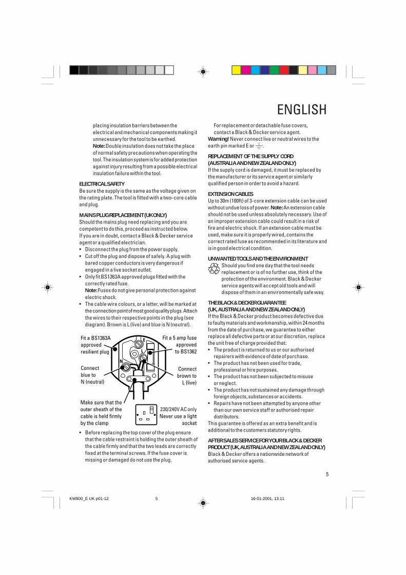
• The cable wire colours, or a letter, will be marked atthe connection point of most good quality plugs. Attachthe wires to their respective points in the plug (seediagram). Brown is L (live) and blue is N (neutral).
Fit a 5 amp fuseapprovedto BS1362
N
L
E
230 volts AC only Never use a light
socket
Make sure that the outer sheath of the cable is held firmly by the clamp
Fit a BS1363A approved resilient plug
Connect blue to N (neutral)
Connect brown to
L (live)
• Before replacing the top cover of the plug ensurethat the cable restraint is holding the outer sheath ofthe cable firmly and that the two leads are correctlyfixed at the terminal screws. If the fuse cover ismissing or damaged do not use the plug.
ENGLISHFor replacement or detachable fuse covers,contact a Black & Decker service agent.
Warning! Never connect live or neutral wires to theearth pin marked E or .
REPLACEMENT OF THE SUPPLY CORD(AUSTRALIA AND NEW ZEALAND ONLY)If the supply cord is damaged, it must be replaced bythe manufacturer or its service agent or similarlyqualified person in order to avoid a hazard.
EXTENSION CABLESUp to 30m (100ft) of 3-core extension cable can be usedwithout undue loss of power. Note: An extension cableshould not be used unless absolutely necessary. Use ofan improper extension cable could result in a risk offire and electric shock. If an extension cable must beused, make sure it is properly wired, contains thecorrect rated fuse as recommended in its literature andis in good electrical condition.
UNWANTED TOOLS AND THE ENVIRONMENTShould you find one day that the tool needsreplacement or is of no further use, think of theprotection of the environment. Black & Deckerservice agents will accept old tools and willdispose of them in an environmentally safe way.
THE BLACK & DECKER GUARANTEE(UK, AUSTRALIA AND NEW ZEALAND ONLY)If the Black & Decker product becomes defective dueto faulty materials and workmanship, within 24 monthsfrom the date of purchase, we guarantee to eitherreplace all defective parts or at our discretion, replacethe unit free of charge provided that:• The product is returned to us or our authorised
repairers with evidence of date of purchase.• The product has not been used for trade,
professional or hire purposes.• The product has not been subjected to misuse
or neglect.• The product has not sustained any damage through
foreign objects, substances or accidents.• Repairs have not been attempted by anyone other
than our own service staff or authorised repairdistributors.
This guarantee is offered as an extra benefit and isadditional to the customers statutory rights.
AFTER SALES SERVICE FOR YOUR BLACK & DECKERPRODUCT (UK, AUSTRALIA AND NEW ZEALAND ONLY)Black & Decker offers a nationwide network ofauthorised service agents.
230/240V AC only
KW800_E UK p01-12 16-01-2001, 13:115
6
ENGLISHThe use of other than genuine Black & Deckeraccessories and parts may damage or reduce theperformance of your Black & Decker product andmay also endanger the user. The terms andconditions of the warranty may also be effected.
OUR AFTER SALES SERVICE POLICY(UK, AUSTRALIA AND NEW ZEALAND ONLY)It is our aim that all Black & Decker customers shouldbe totally satisfied with their Black & Decker productand after sales service, but if help or advice is neededplease contact your local Black & Decker authorisedrepair agent who will be happy to help. Full details ofour after sales service and a list of these agents can befound on the Internet at www.2helpU.com. Alternatively,call our Service and Information Centre whose numberyou will find towards the back of this manual.
ACCESSORIESThe performance of any power tool is dependant uponthe accessory used. Black & Decker accessories areengineered to high quality standards and are designedto enhance the performance of your tool. Buying aBlack & Decker accessory will ensure that you get thevery best from your Black & Decker tool.For full details of accessories available, pleaseconsult your nearest stockist or service agent.
TECHNICAL DATAThe level of sound pressure of the tool is in accordancewith EEC legislation. It is recommended that you takeappropriate measures for the protection of your hearingif the sound level seems uncomfortable.
KW800 KW800EVolts (V) ~ 230 230Input power (W) 710 800No load speed/min 30,000 8,000-30,000
The Black & Decker policy is one of continuous improve-ment to our product and as such we reserve the rightto change the product specification without prior notice.
Note: This user manual may also cover more than onecatalogue number within this product group. Refer toyour rating plate for details of your product. Yourproduct includes some or all of these features.
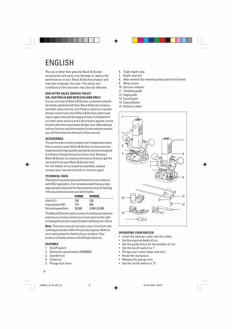
FEATURES1. On/off switch2. Electronic speed switch (KW800E)3. Spindle lock4. Collet nut5. Plunge lock lever
6. Triple depth stop7. Depth stop bar8. Allen wrench (for removing motor pack from frame)9. Wing screw10. Vacuum adaptor11. Template guide12. Edge guide13. Centring pin14. Copy follower15. Distance plate
OPERATING YOUR ROUTER• Insert the desired cutter into the collet.• Set the required depth of cut.• Set the guide fence for the position of cut.• Set the on/off switch to ‘I’.• Plunge your router down and lock.• Route the workpiece.• Release the plunge lock.• Set the on/off switch to ‘O’.
10
15
12
13
•
•
•
•
•
•
2
5
3
17
•
•
••
••
•
8
• 6
•
KW800_E UK p01-12 18-01-2001, 09:076
7
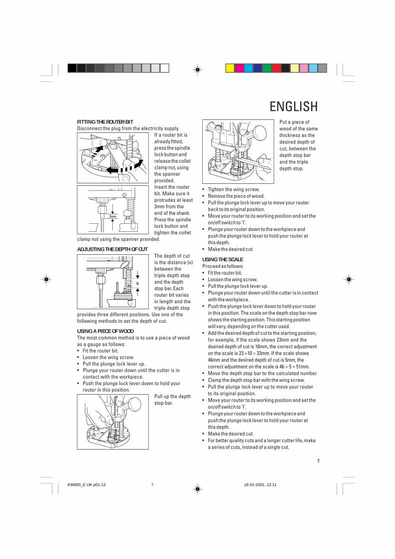
ENGLISHFITTING THE ROUTER BITDisconnect the plug from the electricity supply.
If a router bit isalready fitted,press the spindlelock button andrelease the colletclamp nut, usingthe spannerprovided.Insert the routerbit. Make sure itprotrudes at least3mm from theend of the shank.Press the spindlelock button andtighten the collet
clamp nut using the spanner provided.
ADJUSTING THE DEPTH OF CUTThe depth of cutis the distance (x)between thetriple depth stopand the depthstop bar. Eachrouter bit variesin length and thetriple depth stop
provides three different positions. Use one of thefollowing methods to set the depth of cut.
USING A PIECE OF WOODThe most common method is to use a piece of woodas a gauge as follows:• Fit the router bit.• Loosen the wing screw.• Pull the plunge lock lever up.• Plunge your router down until the cutter is in
contact with the workpiece.• Push the plunge lock lever down to hold your
router in this position.Pull up the depthstop bar.
Put a piece ofwood of the samethickness as thedesired depth ofcut, between thedepth stop barand the tripledepth stop.
• Tighten the wing screw.• Remove the piece of wood.• Pull the plunge lock lever up to move your router
back to its original position.• Move your router to its working position and set the
on/off switch to ‘I’.• Plunge your router down to the workpiece and
push the plunge lock lever to hold your router atthis depth.
• Make the desired cut.
USING THE SCALEProceed as follows:• Fit the router bit.• Loosen the wing screw.• Pull the plunge lock lever up.• Plunge your router down until the cutter is in contact
with the workpiece.• Push the plunge lock lever down to hold your router
in this position. The scale on the depth stop bar nowshows the starting position. This starting positionwill vary, depending on the cutter used.
• Add the desired depth of cut to the starting position;for example, if the scale shows 23mm and thedesired depth of cut is 10mm, the correct adjustmenton the scale is 23 +10 = 33mm. If the scale shows46mm and the desired depth of cut is 5mm, thecorrect adjustment on the scale is 46 + 5 = 51mm.
• Move the depth stop bar to the calculated number.• Clamp the depth stop bar with the wing screw.• Pull the plunge lock lever up to move your router
to its original position.• Move your router to its working position and set the
on/off switch to ‘I’.• Plunge your router down to the workpiece and
push the plunge lock lever to hold your router atthis depth.
• Make the desired cut.• For better quality cuts and a longer cutter life, make
a series of cuts, instead of a single cut.
x
3mm
KW800_E UK p01-12 16-01-2001, 13:117
8
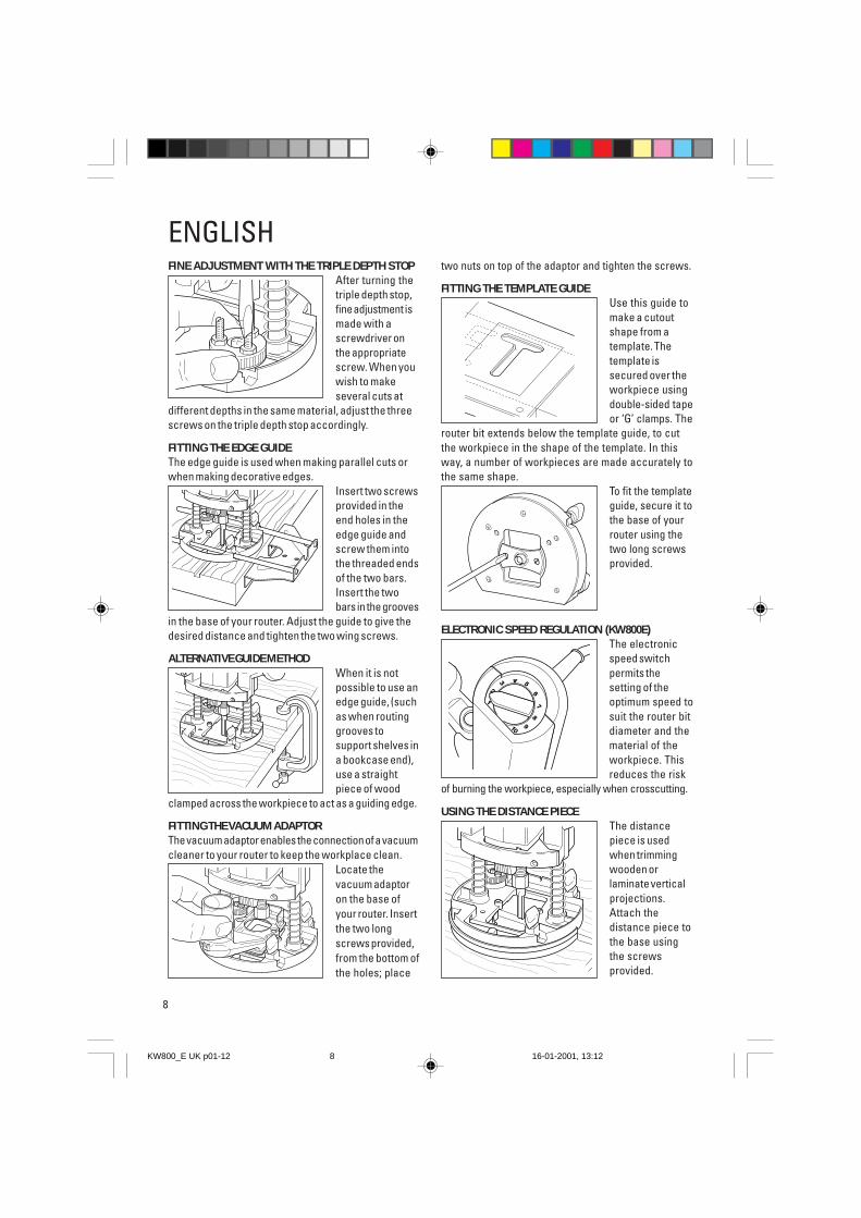
FINE ADJUSTMENT WITH THE TRIPLE DEPTH STOPAfter turning thetriple depth stop,fine adjustment ismade with ascrewdriver onthe appropriatescrew. When youwish to makeseveral cuts at
different depths in the same material, adjust the threescrews on the triple depth stop accordingly.
FITTING THE EDGE GUIDEThe edge guide is used when making parallel cuts orwhen making decorative edges.
Insert two screwsprovided in theend holes in theedge guide andscrew them intothe threaded endsof the two bars.Insert the twobars in the grooves
in the base of your router. Adjust the guide to give thedesired distance and tighten the two wing screws.
ALTERNATIVE GUIDE METHODWhen it is notpossible to use anedge guide, (suchas when routinggrooves tosupport shelves ina bookcase end),use a straightpiece of wood
clamped across the workpiece to act as a guiding edge.
FITTING THE VACUUM ADAPTORThe vacuum adaptor enables the connection of a vacuumcleaner to your router to keep the workplace clean.
Locate thevacuum adaptoron the base ofyour router. Insertthe two longscrews provided,from the bottom ofthe holes; place
two nuts on top of the adaptor and tighten the screws.
FITTING THE TEMPLATE GUIDEUse this guide tomake a cutoutshape from atemplate. Thetemplate issecured over theworkpiece usingdouble-sided tapeor ‘G’ clamps. The
router bit extends below the template guide, to cutthe workpiece in the shape of the template. In thisway, a number of workpieces are made accurately tothe same shape.
To fit the templateguide, secure it tothe base of yourrouter using thetwo long screwsprovided.
ELECTRONIC SPEED REGULATION (KW800E)The electronicspeed switchpermits thesetting of theoptimum speed tosuit the router bitdiameter and thematerial of theworkpiece. Thisreduces the risk
of burning the workpiece, especially when crosscutting.
USING THE DISTANCE PIECEThe distancepiece is usedwhen trimmingwooden orlaminate verticalprojections.Attach thedistance piece tothe base usingthe screwsprovided.
ENGLISH
56
432
1
78
910
KW800_E UK p01-12 16-01-2001, 13:128
9
USING THE CENTRING PINThe centring pinenables you to useyour router as acompass to cut out,scribe or producecircular patterns.Attach the
centring pin to the edge guide with the screw provided.
USING THE COPY FOLLOWERThe copy follower helps maintain an equal cuttingdistance along the edge of irregularly shaped workpieces.To fit the copy follower, proceed as follows:
Attach the ‘L’ bar(a) to the edgeguide (b) usingthe two screwsand nutsprovided. Attachthe rotatingattachment (c) tothe ‘L’ bar withthe wing screw
provided. Adjust the edge guide in the base of yourrouter until the wheel is in contact with the workpiece.
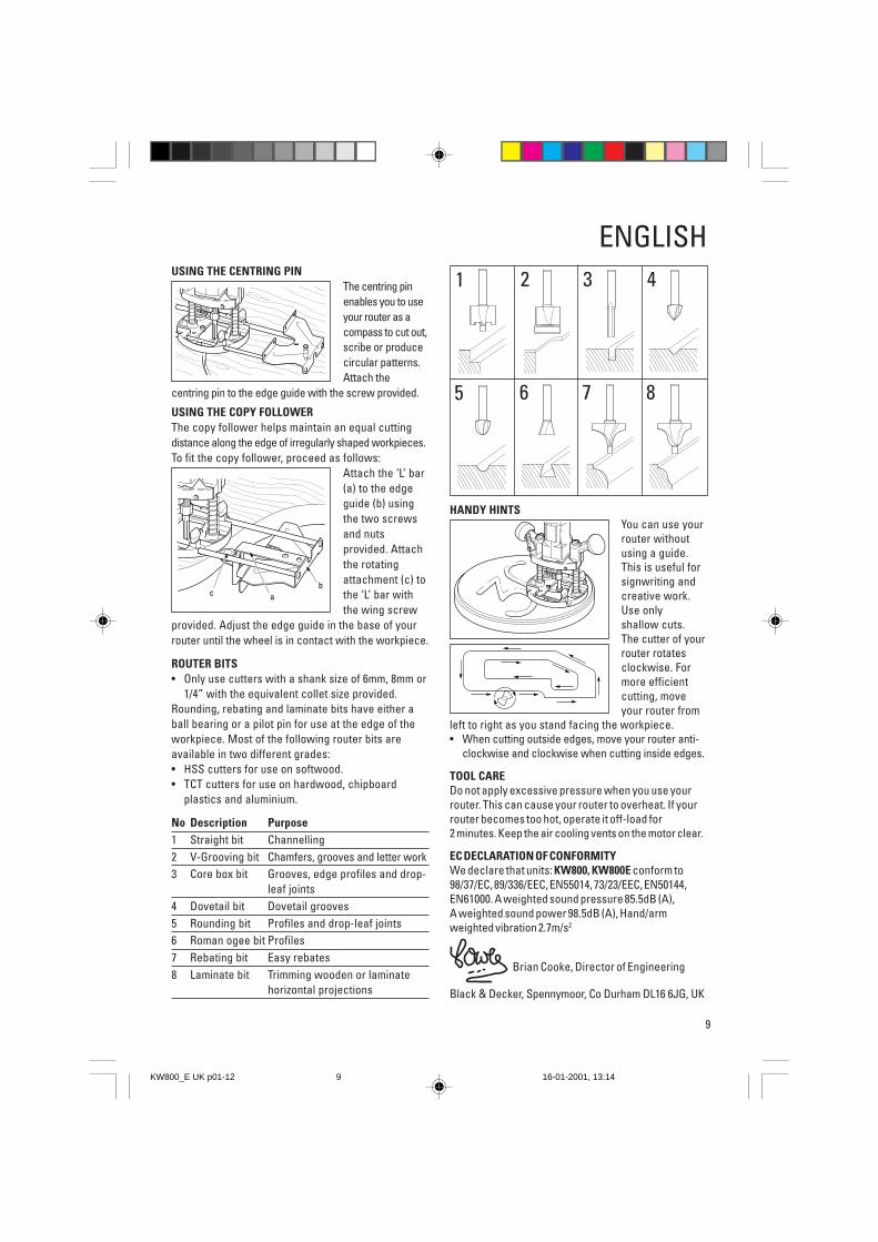
ROUTER BITS• Only use cutters with a shank size of 6mm, 8mm or
1/4” with the equivalent collet size provided.Rounding, rebating and laminate bits have either aball bearing or a pilot pin for use at the edge of theworkpiece. Most of the following router bits areavailable in two different grades:• HSS cutters for use on softwood.• TCT cutters for use on hardwood, chipboard
plastics and aluminium.
No Description Purpose1 Straight bit Channelling2 V-Grooving bit Chamfers, grooves and letter work3 Core box bit Grooves, edge profiles and drop-
leaf joints4 Dovetail bit Dovetail grooves5 Rounding bit Profiles and drop-leaf joints6 Roman ogee bit Profiles7 Rebating bit Easy rebates8 Laminate bit Trimming wooden or laminate
horizontal projections
HANDY HINTSYou can use yourrouter withoutusing a guide.This is useful forsignwriting andcreative work.Use onlyshallow cuts.The cutter of yourrouter rotatesclockwise. Formore efficientcutting, moveyour router from
left to right as you stand facing the workpiece.• When cutting outside edges, move your router anti-
clockwise and clockwise when cutting inside edges.
TOOL CAREDo not apply excessive pressure when you use yourrouter. This can cause your router to overheat. If yourrouter becomes too hot, operate it off-load for2 minutes. Keep the air cooling vents on the motor clear.
EC DECLARATION OF CONFORMITYWe declare that units: KW800, KW800E conform to98/37/EC, 89/336/EEC, EN55014, 73/23/EEC, EN50144,EN61000. A weighted sound pressure 85.5dB (A),A weighted sound power 98.5dB (A), Hand/armweighted vibration 2.7m/s2
Brian Cooke, Director of Engineering
Black & Decker, Spennymoor, Co Durham DL16 6JG, UK
ENGLISH1 2 3 4
5 6 7 8
c ab
KW800_E UK p01-12 16-01-2001, 13:149

01/01
Australia DeWalt Industrial Power Tool Company Tel: 03 9895 9200(Distributors of Black & Decker products) Fax: 03 9899 74657 Clarice Road, Box Hill, Victoria 3128
New Zealand Black & Decker Tel: 09 579 7600483 Great South Road Fax: 09 579 8200Penrose, Auckland
South Africa Black & Decker South Africa (Pty) Ltd Tel: 011 314 4431Suite no 107, PostNet X65 Fax: 011 314 4435Halfway House 1685
United Kingdom Black & Decker Tel: 01753 574277210 Bath Road, Slough Tlx: 848317 BAND MHBerkshire SL1 3YD Fax: 01753 551155
KW800_E UK p01-12 16-01-2001, 13:1210

Addr
ess
of th
e de
aler
whe
re y
our r
oute
r was
pur
chas
ed:
Date
of y
our p
urch
ase:
Was
you
r rou
ter a
gift
?
Was
you
r rou
ter y
our f
irst p
urch
ase?
Was
you
r rou
ter b
ough
t as
a re
plac
emen
t?
Wha
t was
the
pric
e of
you
r rou
ter?
Addr
ess
of th
e de
aler
whe
re y
our r
oute
r was
pur
chas
ed:
Nam
e:
Hous
e nu
mbe
r or n
ame
and
stre
et:
Tow
n:
Coun
ty o
r sta
te:
Post
code
:
Coun
try:
Prod
uct c
atal
ogue
num
ber:
KW80
0/_
Dat
a pr
otec
tion
act:
Tick
this
box
if y
ou p
refe
r not
to re
ceiv
ein
form
atio
n fro
m B
lack
& D
ecke
r or o
ther
com
pani
es.
Yes
N
o
KW800_E UK p01-12 16-01-2001, 13:1211
01/01
GUARANTEE CARD FOR THE UK, IRELAN
D AND SOUTH AFRICA
South Africa: Black & Decker South Africa (Pty) Ltd, Suite no 107, PostN
et X65, Halfway House 1685
United Kingdom &
Ireland: PO Box 821, Slough, Berkshire, SL1 3AR
Please complete this section im
mediately after the purchase of your router
and post it to the Black & Decker address in your country (above).
If you live in Australia or New
Zealand, please register your purchase by usingthe alternative guarantee card supplied.
KW800_E UK p01-12 16-01-2001, 13:1212