Embed Size (px)
Citation preview

Issued: 05.03.20
Issued: 05.03.2008 Version: LastRecentFinal en
KUKA Robot Group
KUKA System Technology (KST)
KUKA.XRob RCSRobot Calibration System
For KUKA System Software (KSS) 5.5

© Copyright 2008
KUKA Roboter GmbHZugspitzstraße 140D-86165 AugsburgGermany
This documentation or excerpts therefrom may not be reproduced or disclosed to third parties without the express permission of the KUKA ROBOT GROUP.
Other functions not described in this documentation may be operable in the controller. The user has no claims to these functions, however, in the case of a replacement or service work.
We have checked the content of this documentation for conformity with the hardware and software de-scribed. Nevertheless, discrepancies cannot be precluded, for which reason we are not able to guaran-tee total conformity. The information in this documentation is checked on a regular basis, however, and necessary corrections will be incorporated in the subsequent edition.
Subject to technical alterations without an effect on the function.
KIM-PS5-DOC
V0.4 22.03.2006 pub de
KUKA.XRob RCS
2 / 53 Issued: 05.03.2008 Version: LastRecentFinal en
Publication: Pub XRob RCS enBook structure: KUKA.XRob RCS V0.1Label: LastRecentFinal
Issu
Contents
1 Introduction ...................................................................................................... 5
1.1 Target group ................................................................................................................... 51.2 Robot system documentation ......................................................................................... 51.3 Representation of warnings and notes ........................................................................... 51.4 Terms used ..................................................................................................................... 61.5 Trademarks ..................................................................................................................... 6
2 Product description ......................................................................................... 7
2.1 Overview KUKA.XRob RCS ........................................................................................... 72.2 Functional principle ......................................................................................................... 7
3 Safety ................................................................................................................ 9
4 Installation ....................................................................................................... 11
4.1 Installation overview ....................................................................................................... 114.2 System requirements ...................................................................................................... 114.3 Installing Microsoft SQL Server Desktop Engine ............................................................ 114.4 Uninstalling XRob database ........................................................................................... 124.5 Installing XRob.RCS database ....................................................................................... 124.6 Installing XRob.RCS database configurator ................................................................... 124.7 Uninstalling XRob.RCS database configurator ............................................................... 124.8 Installing XRob.RCS Wizard ........................................................................................... 134.9 Uninstalling XRob.RCS Wizard ...................................................................................... 134.10 Re-installing XRob.RCS Wizard ..................................................................................... 13
5 Configuration ................................................................................................... 15
5.1 Configuration overview ................................................................................................... 155.2 Opening the database configurator ................................................................................ 155.2.1 Saving settings .......................................................................................................... 165.3 Entering data in the database configurator .................................................................... 165.3.1 Entering tool data ...................................................................................................... 165.3.2 Entering load data ..................................................................................................... 175.3.3 Entering base data .................................................................................................... 195.3.4 Entering robot type data ............................................................................................ 205.3.4.1 Creating a new hole pattern ....................................................................................... 215.3.5 Entering robot data .................................................................................................... 215.3.6 Entering pose data .................................................................................................... 225.4 Editing data ..................................................................................................................... 235.4.1 Editing tool data ......................................................................................................... 235.4.2 Editing load data ........................................................................................................ 235.4.3 Editing base data ....................................................................................................... 245.4.4 Editing robot type data ............................................................................................... 245.4.5 Editing robot data ...................................................................................................... 245.4.6 Editing pose data ....................................................................................................... 245.5 Configuring robot types ................................................................................................... 255.5.1 Creating a new configuration ..................................................................................... 255.5.2 Editing a configuration ............................................................................................... 26
Contents
3 / 53ed: 05.03.2008 Version: LastRecentFinal en
KUKA.XRob RCS
5.5.2.1 Selecting a configuration ........................................................................................... 265.5.2.2 Modifying a configuration ........................................................................................... 275.6 Configuration file XROBCONFIG.XML ........................................................................... 27
6 Operation .......................................................................................................... 31
6.1 Zero mastering with the RCS Wizard ............................................................................. 316.2 Zero mastering for KR spot and KR 5 with the RCS Wizard .......................................... 336.3 Absolute calibration with the RCS Wizard ...................................................................... 35
7 Messages .......................................................................................................... 39
7.1 Viewing messages in the Event Viewer .......................................................................... 397.2 Error messages .............................................................................................................. 39
8 Troubleshooting ............................................................................................... 43
8.1 Causes of errors during the test measurement .............................................................. 43
9 KUKA Service ................................................................................................... 45
9.1 Requesting support ......................................................................................................... 459.2 KUKA Customer Support ................................................................................................ 45
Index .................................................................................................................. 51
4 / 53 Issued: 05.03.2008 Version: LastRecentFinal en
Issu
1. Introduction
1 Introduction
1.1 Target group
This documentation is aimed at users with the following knowledge and skills:
Advanced KRL programming skillsAdvanced knowledge of the robot controller systemAdvanced knowledge of measuring technologyAdvanced knowledge of sensor systemsAdvanced knowledge of image processing
1.2 Robot system documentation
The robot system documentation consists of the following parts:
Operating instructions for the robotOperating instructions for the robot controllerOperating and programming instructions for the KUKA System SoftwareDocumentation relating to options and accessories
Each of these sets of instructions is a separate document.
1.3 Representation of warnings and notes
Safety Warnings marked with this pictogram are relevant to safety and must be ob-served.
Notes Notes marked with this pictogram contain tips to make your work easier or ref-erences to further information.
For optimal use of our products, we recommend that our customers take part in a course of training at KUKA College. Information about the training pro-gram can be found at www.kuka.com or can be obtained directly from our subsidiaries.
Danger!This warning means that death, severe physical injury or substantial material damage will occur, if no precautions are taken.
Warning!This warning means that death, severe physical injury or substantial material damage may occur, if no precautions are taken.
Caution!This warning means that minor physical injuries or minor material damage may occur, if no precautions are taken.
Tips to make your work easier or references to further information.
5 / 53ed: 05.03.2008 Version: LastRecentFinal en
KUKA.XRob RCS
1.4 Terms used
1.5 Trademarks
Microsoft is a trademark of Microsoft Corporation.
Windows is a trademark of Microsoft Corporation.
Term DescriptionHole pattern Position of the drilled holesDB DatabaseHD = hard disk Hard driveCamera frame A result file when calibrating with
the Krypton systemKrypton computer PC with Krypton software installedKrypton strober Distributor for connecting multiple
LEDs to a single outputPID data Parameter identification file of the
robotRDC Resolver Digital ConverterRCS Robot calibration systemTool LEDs LEDs that are calibrated by the
Krypton camera during every cali-bration operation.
Tool locating holes Tool locating holes are required for measuring the tool with the Krypton camera.
X-Rob XRob stands for a product family.
6 / 53 Issued: 05.03.2008 Version: LastRecentFinal en
Issu
2. Product description
2 Product description
2.1 Overview KUKA.XRob RCS
KUKA.XRob RCS is an add-on technology package with the following func-tions:
Functions XRob RCS configuration database for configuration of robot types.XRob RCS Wizard for execution of zero mastering and absolute calibra-tion.
2.2 Functional principle
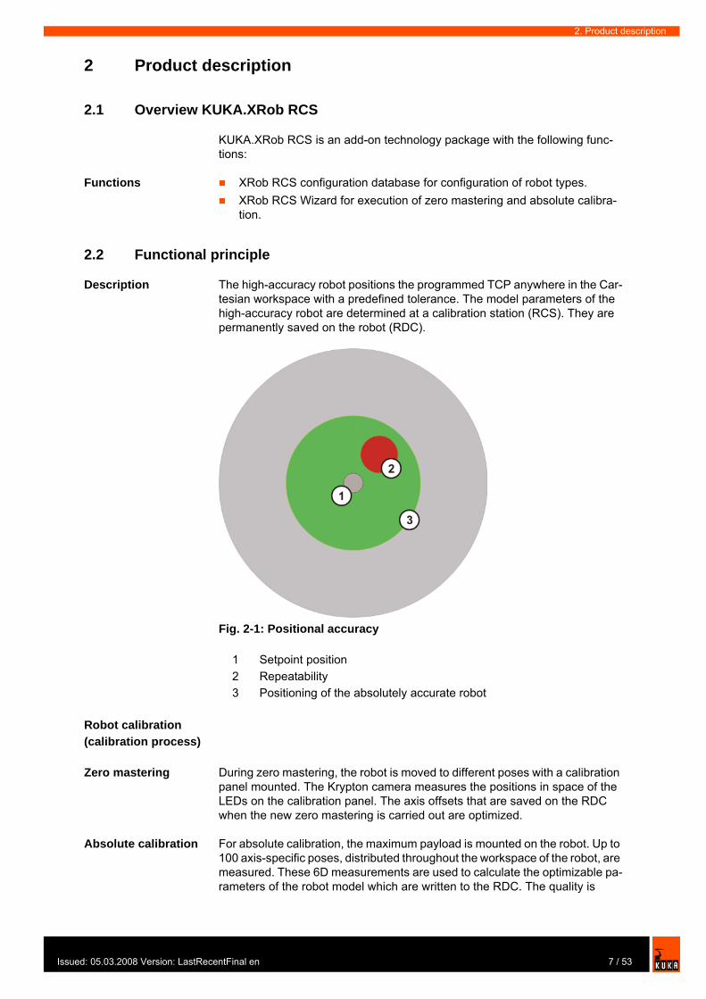
Description The high-accuracy robot positions the programmed TCP anywhere in the Car-tesian workspace with a predefined tolerance. The model parameters of the high-accuracy robot are determined at a calibration station (RCS). They are permanently saved on the robot (RDC).
Robot calibration (calibration process)
Zero mastering During zero mastering, the robot is moved to different poses with a calibration panel mounted. The Krypton camera measures the positions in space of the LEDs on the calibration panel. The axis offsets that are saved on the RDC when the new zero mastering is carried out are optimized.
Absolute calibration For absolute calibration, the maximum payload is mounted on the robot. Up to 100 axis-specific poses, distributed throughout the workspace of the robot, are measured. These 6D measurements are used to calculate the optimizable pa-rameters of the robot model which are written to the RDC. The quality is
Fig. 2-1: Positional accuracy
1 Setpoint position 2 Repeatability 3 Positioning of the absolutely accurate robot
7 / 53ed: 05.03.2008 Version: LastRecentFinal en
KUKA.XRob RCS
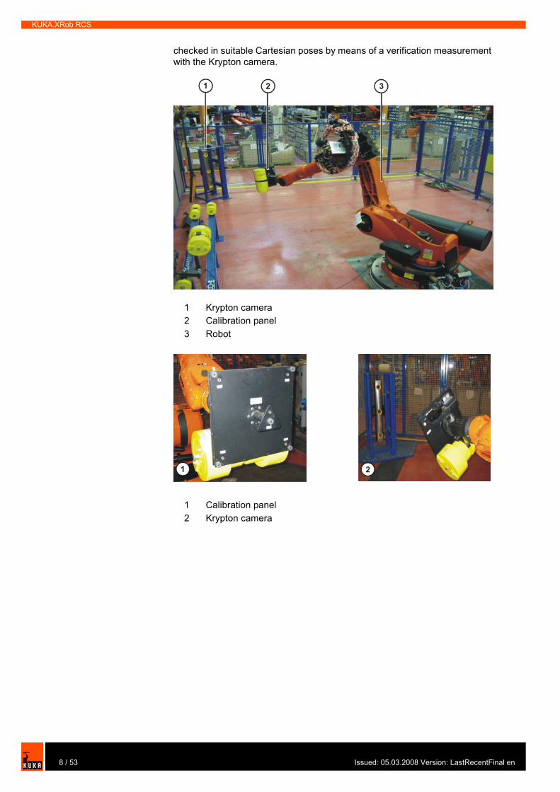
checked in suitable Cartesian poses by means of a verification measurement with the Krypton camera.
1 Krypton camera2 Calibration panel 3 Robot
1 Calibration panel2 Krypton camera
8 / 53 Issued: 05.03.2008 Version: LastRecentFinal en

Issu
3. Safety
3 Safety
All persons working with the robot system must have read and understood the robot system documentation, including the safety chapter.The positionally accurate robot model is only valid for the robot as deliv-ered.Following conversion or retrofitting of the robot, e.g. with an arm extension or a new wrist, the robot must be recalibrated.The robot system with KUKA.XRob RCS must be operated in accordance with the applicable national laws, regulations and standards.
9 / 53ed: 05.03.2008 Version: LastRecentFinal en

KUKA.XRob RCS
10 / 53 Issued: 05.03.2008 Version: LastRecentFinal en
Issu
4. Installation
4 Installation
4.1 Installation overview
4.2 System requirements
Hardware KR C2ed05At least 512 MB RAM
Software Windows XP operating systemKUKA System Software (KSS) 5.5KUKA.UserTech 2.2Microsoft .NET Framework 2.0
4.3 Installing Microsoft SQL Server Desktop Engine
Precondition Windows interfaceLocal administrator rightsAll Windows applications are closed
Procedure 1. Start the program Setup.exe from the CD-ROM.2. Reboot the computer. The installation is resumed and completed.
LOG file LOG files are created in the directory C:\PROGRAM FILES\MICROSOFT SQL SERVER\MSSQL\LOG.
Step Description1 Check system requirements of the
robot controller.
(>>> 4.2 "System requirements" page 11)
2 Install Microsoft SQL Server Desk-top Engine MSDE.
(>>> 4.3 "Installing Microsoft SQL Server Desktop Engine" page 11)
3 Install XRob database.
(>>> 4.5 "Installing XRob.RCS database" page 12)
4 Install KUKA.XRob RCS database configurator.
(>>> 4.6 "Installing XRob.RCS database configurator" page 12)
5 Install KUKA.XRob RCS Wizard.
(>>> 4.8 "Installing XRob.RCS Wizard" page 13)
11 / 53ed: 05.03.2008 Version: LastRecentFinal en
KUKA.XRob RCS
4.4 Uninstalling XRob database
Precondition Microsoft SQL Server Desktop Engine is installed.
Procedure 1. In the Windows Start menu, select Settings > Control Panel > Software and uninstall the Microsoft SQL Server Desktop Engine.
2. Delete the folder MICROSOFT SQL SERVER in the directory C:\PRO-GRAM FILES.
4.5 Installing XRob.RCS database
Precondition Windows interfaceLocal administrator rightsAll Windows applications are closedMicrosoft SQL Server Desktop Engine is installed.
Procedure 1. Start the program Setup.exe from the CD-ROM.The Select Option window is opened.
2. Select Configuration database (Config DB).3. Confirm with Next.
4.6 Installing XRob.RCS database configurator
Precondition Windows XP operating systemMicrosoft .NET Framework 2.0 is installed.Windows interfaceLocal administrator rightsAll Windows applications are closed
Procedure 1. Start the program Setup.exe from the CD-ROM.The Select Option window is opened.
2. Select Database configurator.3. Confirm with Next.
The program is installed under C:\KUKA\XROB_RCS\CONFIGGUI.
4.7 Uninstalling XRob.RCS database configurator
Precondition Windows interfaceKUKA.HMI is switched off.KUKA.XRob RCS database configurator is installed.
Procedure 1. Select the folder Database configurator in the directory C:\KU-KA\XROB_RCS.
It is advisable to archive all relevant data before updating or uninstalling a software package.
It is advisable to archive all relevant data before updating or uninstalling a software package.
12 / 53 Issued: 05.03.2008 Version: LastRecentFinal en
Issu
4. Installation
2. Delete the folder.
4.8 Installing XRob.RCS Wizard
Precondition Windows interfaceKSS 5.5KUKA UserTech 2.3 is installedLocal administrator rightsAll Windows applications are closed.The network connection is established
Procedure 1. Start the program Setup.exe from the CD-ROM.The Select Option window is opened.
2. Select Install XRob RcsWizard.3. Confirm with Next.
The program is installed under C:\KUKA\KRC\TP\XROB_RCS.
4.9 Uninstalling XRob.RCS Wizard
Precondition Windows interfaceKUKA.HMI is switched off.KUKA.XRob RCS is installed.
Procedure 1. Start the UnInstall.exe program in the directory C:\KRC_OPTION\XRO-BRCS\UNINST.
2. Reboot the robot controller. Uninstallation is resumed and completed.
4.10 Re-installing XRob.RCS Wizard
Precondition Windows interfaceLocal administrator rightsAll Windows applications are closedKUKA.HMI is switched offKUKA.XRob RCS is uninstalled.
Procedure 1. Start the ReInstall.exe program in the directory C:\KRC_OPTION\XRO-BRCS\REINST.
2. Reboot the robot controller. Reinstallation is resumed and completed.
LOG file A LOG file is created under C:\KRC\ROBOTER\LOG.
It is advisable to archive all relevant data before updating or uninstalling a software package.
13 / 53ed: 05.03.2008 Version: LastRecentFinal en

KUKA.XRob RCS
14 / 53 Issued: 05.03.2008 Version: LastRecentFinal en
Issu
5. Configuration
5 Configuration
5.1 Configuration overview
5.2 Opening the database configurator
Procedure 1. Start DB Configurator.exe.2. The XRob RCS database configurator opens.
Step Configuration steps1 Open database configurator
(>>> 5.2 "Opening the database configurator" page 15)
2 Enter tool data
(>>> 5.3.1 "Entering tool data" page 16)3 Enter load data
(>>> 5.3.2 "Entering load data" page 17)4 Enter base data
(>>> 5.3.3 "Entering base data" page 19)5 Enter robot type data
(>>> 5.3.4 "Entering robot type data" page 20)6 Enter robot data
(>>> 5.3.5 "Entering robot data" page 21)7 Enter pose data
(>>> 5.3.6 "Entering pose data" page 22)8 Edit tool data
(>>> 5.4.1 "Editing tool data" page 23)9 Edit load data
(>>> 5.4.2 "Editing load data" page 23)10 Edit base data
(>>> 5.4.3 "Editing base data" page 24)11 Edit robot type data
(>>> 5.4.4 "Editing robot type data" page 24)12 Edit robot data
(>>> 5.4.5 "Editing robot data" page 24)13 Edit pose data
(>>> 5.4.6 "Editing pose data" page 24)14 Create new configuration
(>>> 5.5.1 "Creating a new configuration" page 25)15 Edit configuration
(>>> 5.5.2.1 "Selecting a configuration" page 26)
(>>> 5.5.2.2 "Modifying a configuration" page 27)16 Configure RCS Wizard
(>>> 5.6 "Configuration file XROBCONFIG.XML" page 27)
15 / 53ed: 05.03.2008 Version: LastRecentFinal en

KUKA.XRob RCS
3. Select the menu sequence Database > Open.The data linking properties window is opened.
4. Enter server name, user name and password.5. Select database on the server. Confirm with OK.
5.2.1 Saving settings
Description Saving settings of the data linking properties window.
Procedure 1. Open the file DBKonfigurator.config in the directory C:\KU-KA\XRob_Rcs\ConfigGUI.
2. In this file, carry out the settings for the server, user, password and data-base.
3. Select the menu sequence File > Save and close the file.
5.3 Entering data in the database configurator
5.3.1 Entering tool data
Description The tool data contain the following information:
The measurement results of the mechanical calibration of the tool holes.The measurement results of the optical calibration of the LEDs with the Krypton system.The specification of the mass of the tool, flange adapter and panel, without a supplementary load, relative to the flange.The specification of the center of mass of the tool, flange adapter and pan-el, without a supplementary load, relative to the flange.
Precondition The coordinates of the tool LEDs are known and are stored in a file with the extension .tl.The coordinates of the tool locating holes are known.The mass and center of mass of the tool are known.
Procedure 1. Select the menu sequence Data > New > Tool.The input window is opened.
2. Enter an unambiguous designation for the tool in the Designation box.3. Enter a comment in the Comment box (optional).4. Load the coordinates of the tool LEDs by means of the File button. 5. Enter the coordinates of the tool locating holes manually. Click into the box
under X, Y, Z. <edit> appears. Enter the values for X, Y, Z from the cali-bration log of the coordinate measuring machine.
6. Enter the mass of the tool in kg in the Mass box.7. Enter the coordinates for X, Y, Z in mm in the boxes for the center of mass.8. Confirm with OK.
A message window is opened.9. Confirm the message with Yes.
<!-- SQL Server or MSDE configuration --><add key="DBHost" value="PCRC..." /><add key="DBUser" value="xrob..." /><add key="DBPasswd" value="xrob..." /><add key="DBName" value="Messplatz..." />
16 / 53 Issued: 05.03.2008 Version: LastRecentFinal en
Issu
5. Configuration
The data are updated in the database.
5.3.2 Entering load data
Description The load data are factored into the calculation of the paths and accelerations and help to optimize the cycle times.
Various loads can be mounted on the robot:
Payload on the flangeSupplementary load on axis 3Supplementary load on axis 2Supplementary load on axis 1
All loads added together give the overall load.
Fig. 5-1: Entering the tool data
There is a payload diagram for every robot. It can be used to check quickly whether the payload could be suitable for the robot. The diagram is not, how-ever, a substitute for checking the payload with KUKA.Load.
17 / 53ed: 05.03.2008 Version: LastRecentFinal en
KUKA.XRob RCS
Parameters The load data are defined using the following parameters:
Reference systems of the X, Y and Z values for each load:
Precondition The mass and center of mass of the tool are known from the supplemen-tary load data.
Procedure 1. Select the menu sequence Data > New > Load.The input window is opened.
Fig. 5-2: Loads on the robot
1 Payload 3 Supplementary load on axis 22 Supplementary load on axis 3 4 Supplementary load on axis 1
Parameter UnitMass m kgDistance to the center of gravity
Lx, Ly, Lz mm
Mass moments of iner-tia at the center of gravity
Ixx, Iyy, Izz kg m2
Load Reference systemSupplementary load A1
ROBROOT coordinate system
A1 = 0°Supplementary load A2
ROBROOT coordinate system
A2 = -90°Supplementary load A3
FLANGE coordinate system
A4 = 0°, A5 = 0°, A6 = 0°Payload FLANGE coordinate system
18 / 53 Issued: 05.03.2008 Version: LastRecentFinal en
Issu
5. Configuration
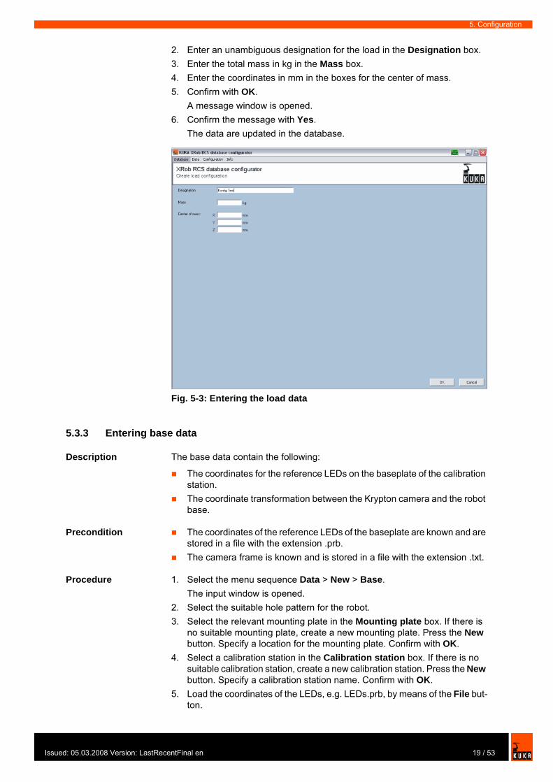
2. Enter an unambiguous designation for the load in the Designation box.3. Enter the total mass in kg in the Mass box.4. Enter the coordinates in mm in the boxes for the center of mass.5. Confirm with OK.
A message window is opened.6. Confirm the message with Yes.
The data are updated in the database.
5.3.3 Entering base data
Description The base data contain the following:
The coordinates for the reference LEDs on the baseplate of the calibration station.The coordinate transformation between the Krypton camera and the robot base.
Precondition The coordinates of the reference LEDs of the baseplate are known and are stored in a file with the extension .prb.The camera frame is known and is stored in a file with the extension .txt.
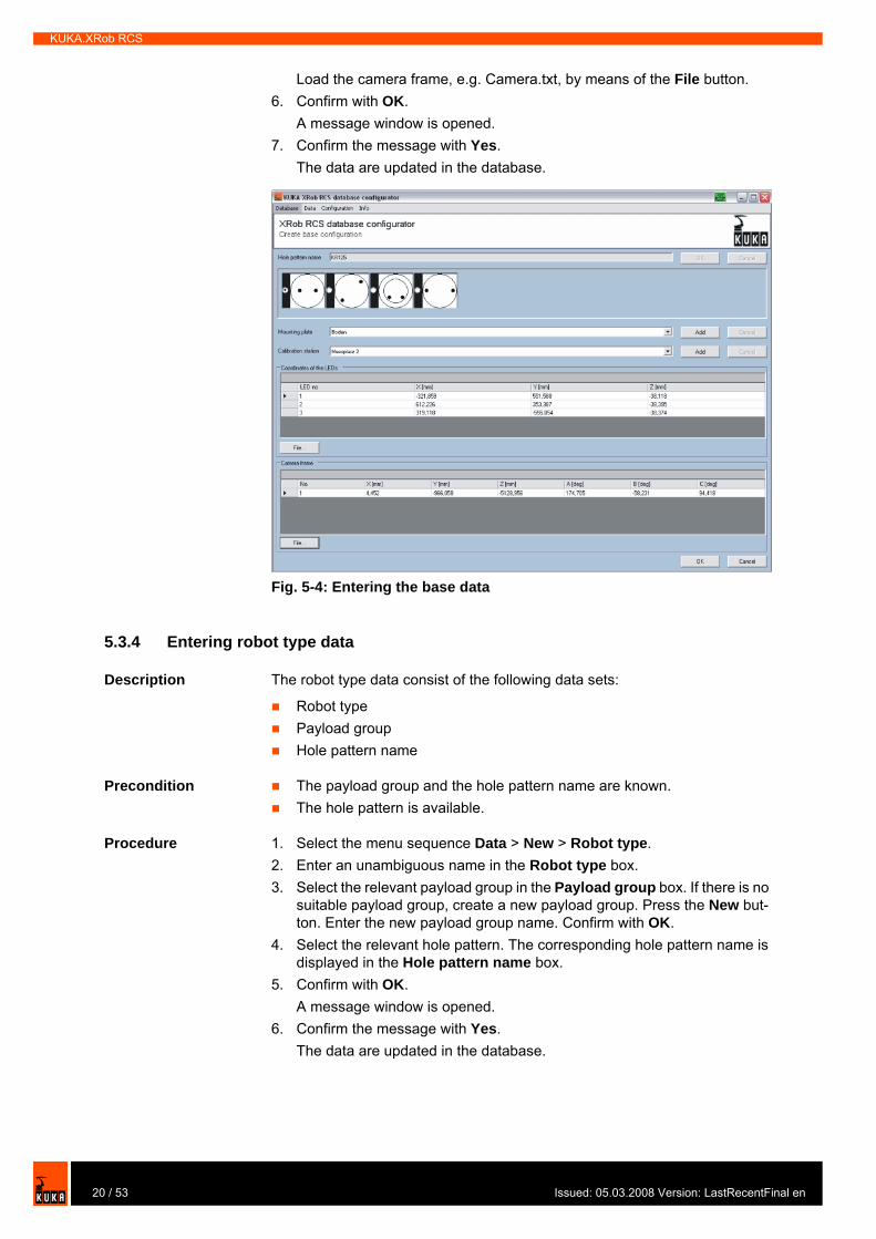
Procedure 1. Select the menu sequence Data > New > Base.The input window is opened.
2. Select the suitable hole pattern for the robot.3. Select the relevant mounting plate in the Mounting plate box. If there is
no suitable mounting plate, create a new mounting plate. Press the New button. Specify a location for the mounting plate. Confirm with OK.
4. Select a calibration station in the Calibration station box. If there is no suitable calibration station, create a new calibration station. Press the New button. Specify a calibration station name. Confirm with OK.
5. Load the coordinates of the LEDs, e.g. LEDs.prb, by means of the File but-ton.
Fig. 5-3: Entering the load data
19 / 53ed: 05.03.2008 Version: LastRecentFinal en
KUKA.XRob RCS
Load the camera frame, e.g. Camera.txt, by means of the File button.6. Confirm with OK.
A message window is opened.7. Confirm the message with Yes.
The data are updated in the database.
5.3.4 Entering robot type data
Description The robot type data consist of the following data sets:
Robot typePayload groupHole pattern name
Precondition The payload group and the hole pattern name are known.The hole pattern is available.
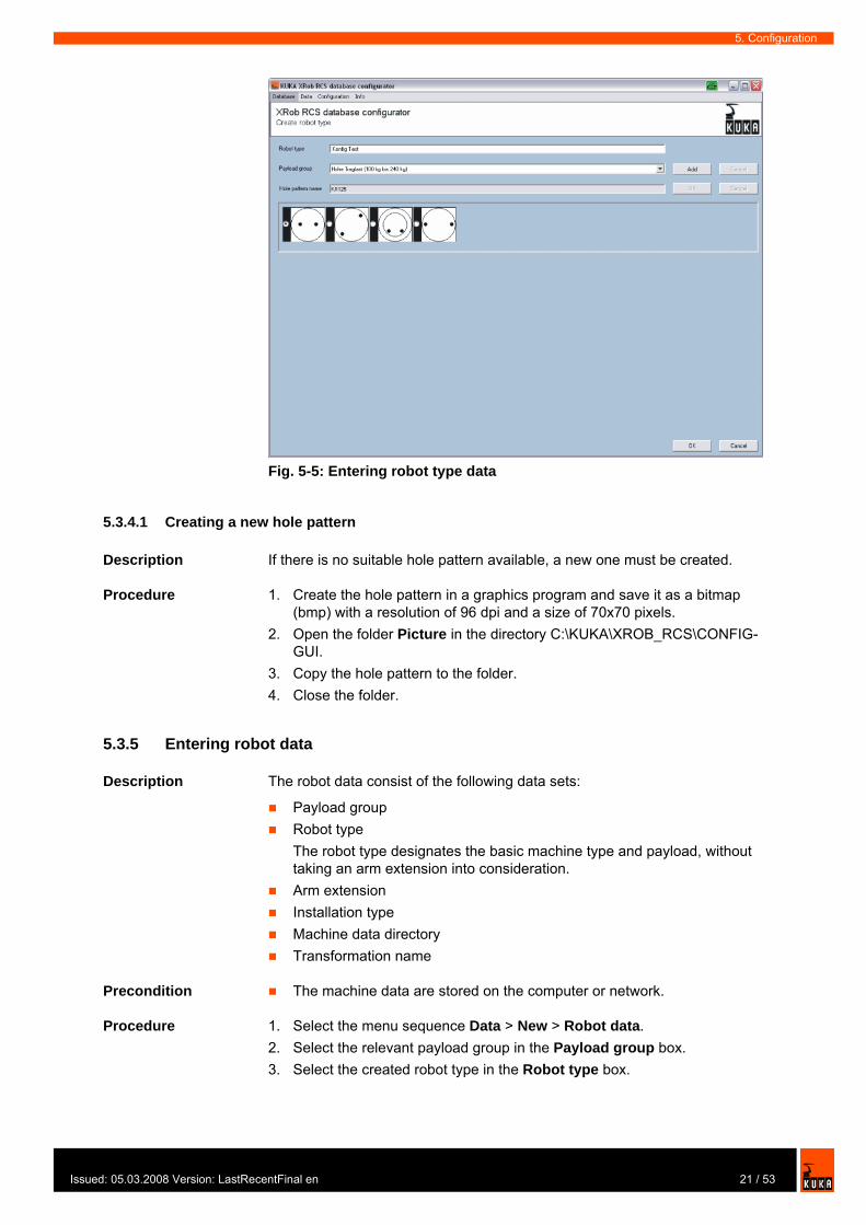
Procedure 1. Select the menu sequence Data > New > Robot type.2. Enter an unambiguous name in the Robot type box.3. Select the relevant payload group in the Payload group box. If there is no
suitable payload group, create a new payload group. Press the New but-ton. Enter the new payload group name. Confirm with OK.
4. Select the relevant hole pattern. The corresponding hole pattern name is displayed in the Hole pattern name box.
5. Confirm with OK.A message window is opened.
6. Confirm the message with Yes.The data are updated in the database.
Fig. 5-4: Entering the base data
20 / 53 Issued: 05.03.2008 Version: LastRecentFinal en
Issu
5. Configuration
5.3.4.1 Creating a new hole pattern
Description If there is no suitable hole pattern available, a new one must be created.
Procedure 1. Create the hole pattern in a graphics program and save it as a bitmap (bmp) with a resolution of 96 dpi and a size of 70x70 pixels.
2. Open the folder Picture in the directory C:\KUKA\XROB_RCS\CONFIG-GUI.
3. Copy the hole pattern to the folder.4. Close the folder.
5.3.5 Entering robot data
Description The robot data consist of the following data sets:
Payload groupRobot typeThe robot type designates the basic machine type and payload, without taking an arm extension into consideration.Arm extensionInstallation typeMachine data directory Transformation name
Precondition The machine data are stored on the computer or network.
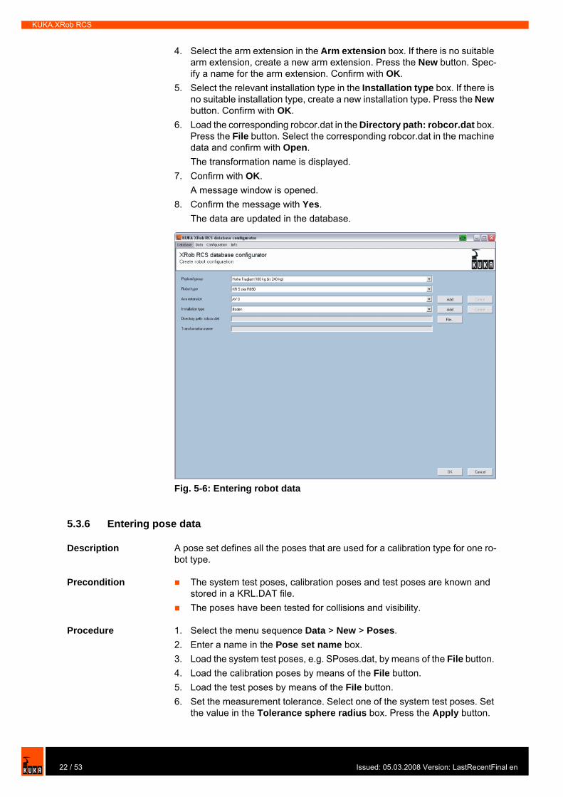
Procedure 1. Select the menu sequence Data > New > Robot data.2. Select the relevant payload group in the Payload group box. 3. Select the created robot type in the Robot type box.
Fig. 5-5: Entering robot type data
21 / 53ed: 05.03.2008 Version: LastRecentFinal en
KUKA.XRob RCS
4. Select the arm extension in the Arm extension box. If there is no suitable arm extension, create a new arm extension. Press the New button. Spec-ify a name for the arm extension. Confirm with OK.
5. Select the relevant installation type in the Installation type box. If there is no suitable installation type, create a new installation type. Press the New button. Confirm with OK.
6. Load the corresponding robcor.dat in the Directory path: robcor.dat box. Press the File button. Select the corresponding robcor.dat in the machine data and confirm with Open.The transformation name is displayed.
7. Confirm with OK.A message window is opened.
8. Confirm the message with Yes.The data are updated in the database.
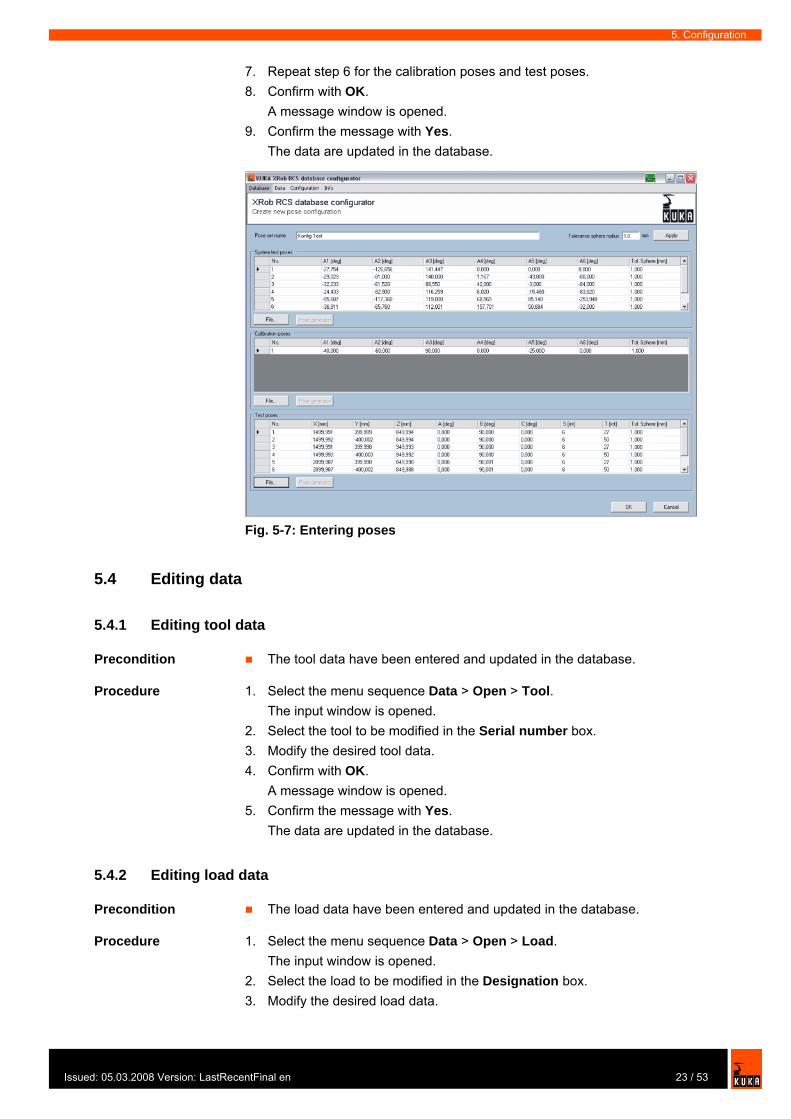
5.3.6 Entering pose data
Description A pose set defines all the poses that are used for a calibration type for one ro-bot type.
Precondition The system test poses, calibration poses and test poses are known and stored in a KRL.DAT file. The poses have been tested for collisions and visibility.
Procedure 1. Select the menu sequence Data > New > Poses.2. Enter a name in the Pose set name box.3. Load the system test poses, e.g. SPoses.dat, by means of the File button. 4. Load the calibration poses by means of the File button. 5. Load the test poses by means of the File button. 6. Set the measurement tolerance. Select one of the system test poses. Set
the value in the Tolerance sphere radius box. Press the Apply button.
Fig. 5-6: Entering robot data
22 / 53 Issued: 05.03.2008 Version: LastRecentFinal en
Issu
5. Configuration
7. Repeat step 6 for the calibration poses and test poses.8. Confirm with OK.
A message window is opened.9. Confirm the message with Yes.
The data are updated in the database.
5.4 Editing data
5.4.1 Editing tool data
Precondition The tool data have been entered and updated in the database.
Procedure 1. Select the menu sequence Data > Open > Tool.The input window is opened.
2. Select the tool to be modified in the Serial number box.3. Modify the desired tool data.4. Confirm with OK.
A message window is opened.5. Confirm the message with Yes.
The data are updated in the database.
5.4.2 Editing load data
Precondition The load data have been entered and updated in the database.
Procedure 1. Select the menu sequence Data > Open > Load.The input window is opened.
2. Select the load to be modified in the Designation box.3. Modify the desired load data.
Fig. 5-7: Entering poses
23 / 53ed: 05.03.2008 Version: LastRecentFinal en
KUKA.XRob RCS
4. Confirm with OK.A message window is opened.
5. Confirm the message with Yes.The data are updated in the database.
5.4.3 Editing base data
Precondition The base data have been entered and updated in the database.
Procedure 1. Select the menu sequence Data > Open > Base.The input window is opened.
2. Modify the desired base data.3. Confirm with OK.
A message window is opened.4. Confirm the message with Yes.
The data are updated in the database.
5.4.4 Editing robot type data
Precondition The robot type data have been entered and updated in the database.
Procedure 1. Select the menu sequence Data > Open > Robot type.The input window is opened.
2. Select the robot type to be modified in the Robot type box.3. Modify the desired robot type data.4. Confirm with OK.
A message window is opened.5. Confirm the message with Yes.
The data are updated in the database.
5.4.5 Editing robot data
Precondition The robot data have been entered and updated in the database.
Procedure 1. Select the menu sequence Data > Open > Robot data.The input window is opened.
2. Modify the desired robot data.3. Confirm with OK.
A message window is opened.4. Confirm the message with Yes.
The data are updated in the database.
5.4.6 Editing pose data
Precondition The pose data have been entered and updated in the database.
Procedure 1. Select the menu sequence Data > Open > Poses.The input window is opened.
2. Select the pose set to be modified in the Pose set name box.3. Modify the desired pose data.
24 / 53 Issued: 05.03.2008 Version: LastRecentFinal en
Issu
5. Configuration
4. Confirm with OK.A message window is opened.
5. Confirm the message with Yes.The data are updated in the database.
5.5 Configuring robot types
5.5.1 Creating a new configuration
Precondition All data have been entered and updated in the database.
Procedure 1. Select the menu sequence Configuration > New.The “Robot type and calibration station” tab is opened.
2. Enter an unambiguous name in the Designation box.3. Enter a comment in the Comment box (optional).4. Select the calibration type in the Calibration type box.5. Activate Configuration active.
Active configurations are now available for selection in the RCS Wizard.6. Select the desired payload group in the Payload group box.7. Select the corresponding robot in the Robot type box.8. Select the desired arm extension in the Arm extension box.9. Select the relevant installation type in the Installation type box.
The corresponding directory path and transformation name are displayed.10. Select the desired calibration station in the Calibration station box.11. Select the corresponding mounting plate in the Base tab.
The hole pattern name, hole pattern, coordinates of the LEDs and the camera frame are displayed.
12. Select the corresponding load in the Designation box on the Load tab.13. Select the corresponding pose in the Pose set name box on the Poses
tab.14. Select the corresponding tool in the Serial number box on the Tool tab.15. Select the relevant model in the Configuration name box on the Model
tab.16. Confirm with OK.
A message window is opened.17. Confirm the message with Yes.
The data are updated in the database.
25 / 53ed: 05.03.2008 Version: LastRecentFinal en

KUKA.XRob RCS
5.5.2 Editing a configuration
5.5.2.1 Selecting a configuration
Procedure 1. Select the menu sequence Configuration > Open.2. Only active configuration activated. Only active configurations can be
selected.Only active configuration not activated. All configurations can be select-ed.
3. Select the desired calibration station in the Calibration station box.4. Select the desired calibration type in the Calibration type box. 5. Select the desired robot type in the Robot type box.6. Select the configuration to be modified in the Configuration box.7. Confirm with Apply.
The “Robot type and calibration station” tab is opened.
Fig. 5-8: Creating a new configuration
26 / 53 Issued: 05.03.2008 Version: LastRecentFinal en

Issu
5. Configuration
5.5.2.2 Modifying a configuration
Precondition New data have been entered.A configuration for a robot type and calibration station has been selected.
Procedure 1. Modify the load in the Designation box on the Load tab.2. Modify the mounting plate in the Mounting plate box on the Base tab.3. Modify the poses in the Pose set name box on the Poses tab.4. Modify the tool in the Serial number box on the Tool tab.5. Modify the model in the Configuration name box on the Model tab.6. Confirm with OK.
A message window is opened.7. Confirm the message with Yes.
The data are updated in the database.
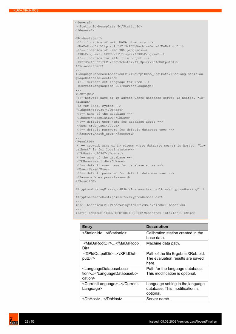
5.6 Configuration file XROBCONFIG.XML
Description In order to be able to exchange data between the computers, links must be en-tered in the XRobConfig file.
The configuration file XROBCONFIG.XML is situated, after installation of KU-KA.XRob RCS, in the directory ...\KRC\TP\XROB_RCS\UTIL.
To edit XROBCONFIG.XML, the file must be opened in edit mode.
Precondition RCS Wizard is installed.Windows interface
Procedure 1. Open the file XRobConfig in the directory C:\KRC\TP\XROB_RCS\UTIL using the editor.
2. Modify the following entries in the file:
27 / 53ed: 05.03.2008 Version: LastRecentFinal en
KUKA.XRob RCS
<General> <StationId>Messplatz 8</StationId></General>...<RcsAssistent> <!-- location of main MADA directory --> <MaDaRootDir>\\pcrc40382_3\RCS\MachineData</MaDaRootDir> <!-- location of used KRL programs--> <KRLProgramDir>KRC:\R1\Program</KRLProgramDir> <!-- location for XPId file output --> <XPIdOutputDir>C:\KRC\Roboter\IR_Spec</XPIdOutputDir></RcsAssistent>...<LanguageDatabaseLocation>C:\krc\tp\XRob_Rcs\Data\XRobLang.mdb</Lan-guageDatabaseLocation> <!-- current set language for xrob --> <CurrentLanguage>de-DE</CurrentLanguage>...<ConfigDB> <!--network name or ip adress where database server is hosted, "lo-calhost" is for local system --> <DbHost>pc40367</DbHost> <!-- name of the database --> <DbName>MessplatzDB</DbName> <!-- default user name for database acces --> <User>xrob_user</User> <!-- default password for default database user --> <Password>xrob_user</Password>...<ResultDB> <!-- network name or ip adress where database server is hosted, "lo-calhost" is for local system--> <DbHost>pc40367</DbHost> <!-- name of the database --> <DbName>resultdb</DbName> <!-- default user name for database acces --> <User>Name</User> <!-- default password for default database user --> <Password>testpas</Password></ResultDB>...<KryptonWorkingDir>\\pc40367\Austausch\rocal\bin</KryptonWorkingDir>...<KryptonRemoteHost>pc40367</KryptonRemoteHost>...<ShellLocation>C:\Windows\system32\cdm.exe</ShellLocation>...<IstFileName>C:\KRC\ROBOTER\IR_SPEC\Messdaten.ist</IstFileName>
Entry Description<StationId>...</StationId> Calibration station created in the
base data. <MaDaRootDir>...</MaDaRoot-Dir>
Machine data path.
<XPIdOutputDir>...</XPIdOut-putDir>
Path of the file ErgebnisXRob.pid. The evaluation results are saved here.
<LanguageDatabaseLoca-tion>...</LanguageDatabaseLo-cation>
Path for the language database. This modification is optional.
<CurrentLanguage>...</Current-Language>
Language setting in the language database. This modification is optional.
<DbHost>...</DbHost> Server name.
28 / 53 Issued: 05.03.2008 Version: LastRecentFinal en

Issu
5. Configuration
<DbName>...</DbName> Database name<User>...</User> Predefined user name. This modi-
fication is optional.<Password>...</Password> Predefined password. This modi-
fication is optional.<KryptonWorkingDir>...</Kryp-tonWorkingDir>
Path specification for the working directory of the Krypton software.
<KryptonRemoteHost>...</Kryp-tonRemoteHost>
Name of the Krypton computer.
<ShellLocation>...</ShellLoca-tion>
Path specification of CMD.exe on the Krypton computer. This modi-fication is optional.
<IstFileName>...</IstFileName> Path for the results database
Entry Description
29 / 53ed: 05.03.2008 Version: LastRecentFinal en

KUKA.XRob RCS
30 / 53 Issued: 05.03.2008 Version: LastRecentFinal en
Issu
6. Operation
6 Operation
6.1 Zero mastering with the RCS Wizard
Precondition Krypton RemoteControl.exe is started on the Krypton computer.The data have been entered and updated in the database.A configuration has been created and updated in the database.The network connection is established.Operating mode T1 or T2.
Procedure 1. Start the KUKA System Software (KSS) 5.5.2. Select the menu sequence Monitor > XRob RCS > Show.3. Press the Next softkey.
A prompt window is displayed.4. Select the calibration type. Press the Zero mastering softkey.
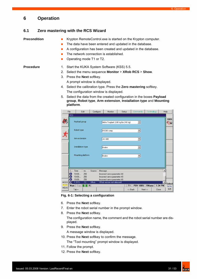
The configuration window is displayed.5. Select the data from the created configuration in the boxes Payload
group, Robot type, Arm extension, Installation type and Mounting platform.
6. Press the Next softkey.7. Enter the robot serial number in the prompt window.8. Press the Next softkey.
The configuration name, the comment and the robot serial number are dis-played.
9. Press the Next softkey.A message window is displayed.
10. Press the Next softkey to confirm the message.The “Tool mounting” prompt window is displayed.
11. Follow the prompt.12. Press the Next softkey.
Fig. 6-1: Selecting a configuration
31 / 53ed: 05.03.2008 Version: LastRecentFinal en
KUKA.XRob RCS
The “Unmaster robot” prompt window is displayed.13. Unmaster the axes.
14. Press the Next softkey.The “Master robot in home position” prompt window is displayed.
15. Master the robot.
16. Press the Next softkey.The “Test measurement for robot type check” prompt window is displayed.
17. Press the Next softkey.The program for checking the robot type is displayed.
18. Set mode selector switch to Automatic mode. Start the program. Once pro-gram execution has been completed, the result is displayed.
19. Press the Next softkey.The “Carry out mastering” prompt window is displayed.
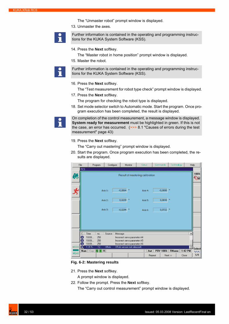
20. Start the program. Once program execution has been completed, the re-sults are displayed.
21. Press the Next softkey.A prompt window is displayed.
22. Follow the prompt. Press the Next softkey.The “Carry out control measurement” prompt window is displayed.
Further information is contained in the operating and programming instruc-tions for the KUKA System Software (KSS).
Further information is contained in the operating and programming instruc-tions for the KUKA System Software (KSS).
On completion of the control measurement, a message window is displayed. System ready for measurement must be highlighted in green. If this is not the case, an error has occurred. (>>> 8.1 "Causes of errors during the test measurement" page 43)
Fig. 6-2: Mastering results
32 / 53 Issued: 05.03.2008 Version: LastRecentFinal en
Issu
6. Operation
23. Press the Next softkey to confirm the prompt.The program for the control measurement is displayed.
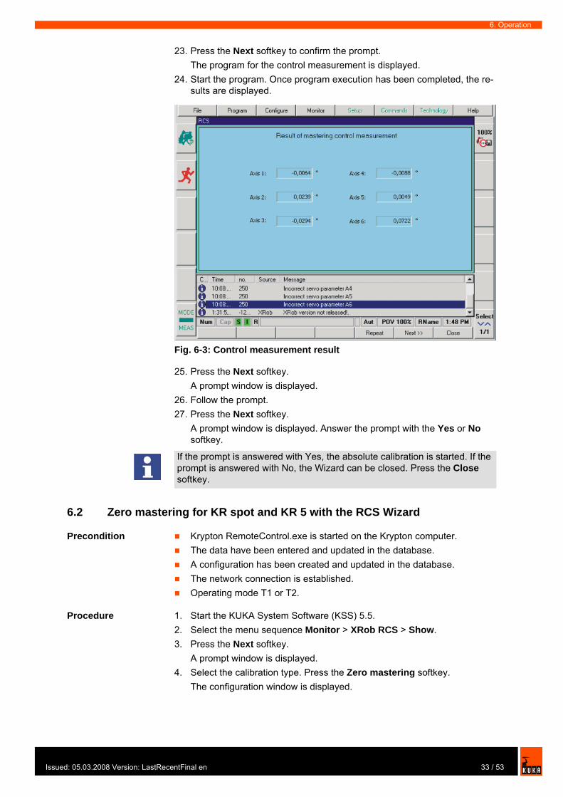
24. Start the program. Once program execution has been completed, the re-sults are displayed.
25. Press the Next softkey.A prompt window is displayed.
26. Follow the prompt.27. Press the Next softkey.
A prompt window is displayed. Answer the prompt with the Yes or No softkey.
6.2 Zero mastering for KR spot and KR 5 with the RCS Wizard
Precondition Krypton RemoteControl.exe is started on the Krypton computer.The data have been entered and updated in the database.A configuration has been created and updated in the database.The network connection is established.Operating mode T1 or T2.
Procedure 1. Start the KUKA System Software (KSS) 5.5.2. Select the menu sequence Monitor > XRob RCS > Show.3. Press the Next softkey.
A prompt window is displayed.4. Select the calibration type. Press the Zero mastering softkey.
The configuration window is displayed.
Fig. 6-3: Control measurement result
If the prompt is answered with Yes, the absolute calibration is started. If the prompt is answered with No, the Wizard can be closed. Press the Close softkey.
33 / 53ed: 05.03.2008 Version: LastRecentFinal en
KUKA.XRob RCS
5. Select the data from the created configuration in the boxes Payload group, Robot type, Arm extension, Installation type and Mounting platform.
6. Press the Next softkey.7. Enter the robot serial number in the prompt window.8. Press the Next softkey.
The configuration name, the comment and the robot serial number are dis-played.
9. Press the Next softkey.A message window is displayed.
10. Press the Next softkey to confirm the message.A prompt window is displayed.
11. Follow the prompt.12. Press the Next softkey.
The “Unmaster robot” prompt window is displayed.13. Unmaster the axes.
14. Press the Next softkey.The “Master robot in home position” prompt window is displayed.
15. Master the robot.
16. Press the Next softkey.The “Test measurement for robot type check” prompt window is displayed.
17. Press the Next softkey.The program for checking the robot type is displayed.
18. Set mode selector switch to Automatic mode. Start the program. Once pro-gram execution has been completed, the result is displayed.
19. Press the Next softkey.The “Carry out mastering” prompt window is displayed.
20. Start the program. Once program execution has been completed, the re-sults are displayed.
21. Press the Next softkey.A prompt window is displayed.
22. Follow the prompt.23. Press the Next softkey.
The “Standard EMT mastering: check mastering” prompt window is dis-played.
24. Check mastering.
25. Press the Next softkey.The “Save MAMES data” prompt window is displayed.
26. Press the Save softkey.The data are saved to the HD, RDC and DB.
Further information is contained in the operating and programming instruc-tions for the KUKA System Software (KSS).
Further information is contained in the operating and programming instruc-tions for the KUKA System Software (KSS).
Further information is contained in the operating and programming instruc-tions for the KUKA System Software (KSS).
34 / 53 Issued: 05.03.2008 Version: LastRecentFinal en

Issu
6. Operation
27. Press the Next softkey.A prompt window is displayed. Answer the prompt with the Yes or No softkey.
6.3 Absolute calibration with the RCS Wizard
Precondition Krypton RemoteControl.exe is started on the Krypton computer.The data have been entered and updated in the database.A configuration has been created and updated in the database.The network connection is established.Operating mode T1 or T2.
Procedure 1. Start the KUKA System Software (KSS) 5.5.2. Select the menu sequence Monitor > XRob RCS > Show.3. Press the Next softkey.
A prompt window is displayed.4. Select the calibration type. Press the AbsoluteC softkey.
The prompt is confirmed.The configuration window is displayed.
5. Select the data from the created configuration in the boxes Payload group, Robot type, Arm extension, Installation type and Mounting platform.
6. Press the Next softkey.7. Enter the robot serial number in the prompt window.8. Press the Next softkey.
The configuration name, the entered comment and the robot serial number are displayed.
If the prompt is answered with Yes, the absolute calibration is started. If the prompt is answered with No, the Wizard can be closed. Press the Close softkey.
Fig. 6-4: Selecting a configuration
35 / 53ed: 05.03.2008 Version: LastRecentFinal en

KUKA.XRob RCS
9. Press the Next softkey.The “Unmaster axes” prompt window is displayed.
10. Unmaster axes.
11. Press the Next softkey.The “Master axes” prompt window is displayed.
12. Master the axes.
13. Press the Next softkey.A message window is displayed.
14. Press the Next softkey to confirm the message.A prompt window is displayed.
15. Follow the prompt.16. Press the Next softkey.
A prompt window is displayed. 17. Press the Next softkey to confirm the prompt.
The program for the control measurement is displayed.18. Set mode selector switch to Automatic mode. Start the program.
19. Set mode selector switch to T1 mode.20. Press the Next softkey.
A prompt window is displayed.21. Press the Next softkey to confirm the prompt.
The program for absolute calibration is displayed.22. Start the program.
Once program execution has been completed, the results are displayed.
Further information is contained in the operating and programming instruc-tions for the KUKA System Software (KSS).
Further information is contained in the operating and programming instruc-tions for the KUKA System Software (KSS).
On completion of the control measurement, a message window is displayed. System ready for measurement must be highlighted in green. If this is not the case, an error has occurred. (>>> 8.1 "Causes of errors during the test measurement" page 43)
36 / 53 Issued: 05.03.2008 Version: LastRecentFinal en
Issu
6. Operation
23. Press the Next softkey.The “Positioning accuracy control measurement run” prompt window is displayed.
24. Press the Next softkey.The program for the positioning accuracy control measurement run is dis-played.
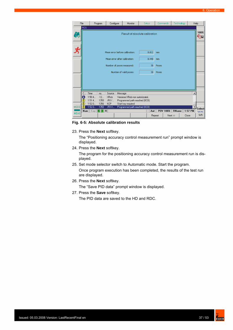
25. Set mode selector switch to Automatic mode. Start the program.Once program execution has been completed, the results of the test run are displayed.
26. Press the Next softkey.The “Save PID data” prompt window is displayed.
27. Press the Save softkey. The PID data are saved to the HD and RDC.
Fig. 6-5: Absolute calibration results
37 / 53ed: 05.03.2008 Version: LastRecentFinal en

KUKA.XRob RCS
38 / 53 Issued: 05.03.2008 Version: LastRecentFinal en
Issu
7. Messages
7 Messages
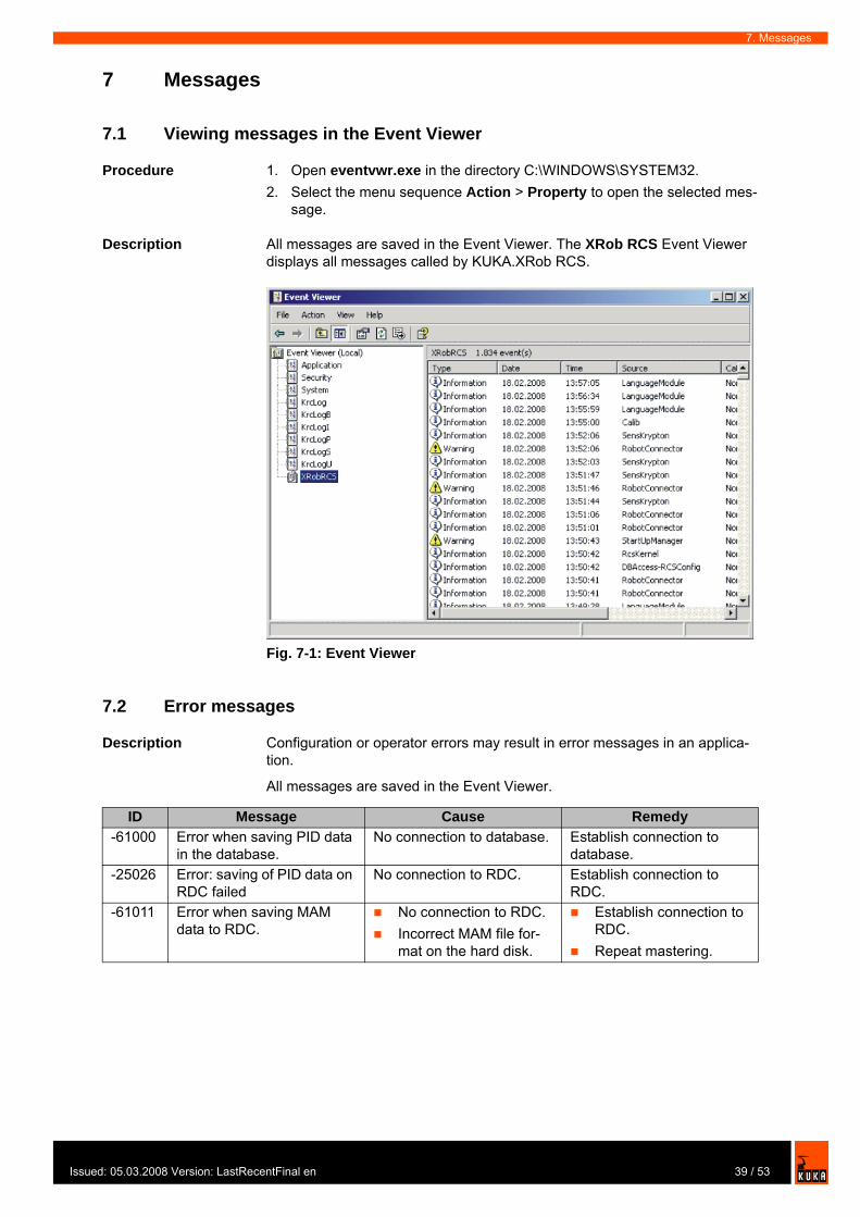
7.1 Viewing messages in the Event Viewer
Procedure 1. Open eventvwr.exe in the directory C:\WINDOWS\SYSTEM32. 2. Select the menu sequence Action > Property to open the selected mes-
sage.
Description All messages are saved in the Event Viewer. The XRob RCS Event Viewer displays all messages called by KUKA.XRob RCS.
7.2 Error messages
Description Configuration or operator errors may result in error messages in an applica-tion.
All messages are saved in the Event Viewer.
Fig. 7-1: Event Viewer
ID Message Cause Remedy-61000 Error when saving PID data
in the database.No connection to database. Establish connection to
database.-25026 Error: saving of PID data on
RDC failedNo connection to RDC. Establish connection to
RDC.-61011 Error when saving MAM
data to RDC.No connection to RDC.Incorrect MAM file for-mat on the hard disk.
Establish connection to RDC.Repeat mastering.
39 / 53ed: 05.03.2008 Version: LastRecentFinal en
KUKA.XRob RCS
-25035 Error: saving of MAM data on hard drive failed.
MAM file could not be gen-erated in the directory C:\KRC\ROBOTER\IR_SPEC.
Deactivate write protec-tion of directory C:\KRC\ROBOT-ER\IR_SPEC.Check that you have ac-cess rights to write to the directory C:\KRC\ROBOT-ER\IR_SPEC.
-25030 Error: MAM file could not be found in IR_SPEC directory.
MAM file <Serial_number>.mam could not be found in the directory C:\KRC\ROBOTER\IR_SPEC.
Compare the file name of the MAM file with the pro-grammed serial number of the robot (file name: <Serial_number>.mam)
-25032 Error: MAM file cannot be loaded from hard drive.
MAM file on hard drive faulty.
Repeat mastering.
-25033 Error: MAM file checksum incorrect.
Contents of the MAM file have been changed. Check sum check indi-cates faulty file integrity.Robot serial number or $Mames values have changed.
Copy the original MAM file to the directory C:\KRC\ROBOT-ER\IR_SPEC.Check the programmed robot serial number and the $Mames values in $machine.dat.
-25037 Error: loading of a KRL vari-able failed.
KRL variable could not be read.
Check whether the KRL variable can be read manu-ally in the variable display of the GUI.
-61005 Error when saving the mas-tering in the database.
No connection to database. Establish connection to database.
-61008 Error when saving meas-ured values to the hard drive.
Measurement values file <Serial_number>.ist could not be generated in the specified directory (see XROBCONFIG.XML).
Deactivate write protec-tion of specified directo-ry (see XROBCONFIG.XML file).Check that you have ac-cess rights to write to the specified directory (see XROBCON-FIG.XML file).
-61010 Error when calculating the mastering difference.
An error has occurred in the GUI function “Check mas-tering”.
Repeat the GUI function “Check mastering”.
-61013 Error when reading $RAT_MOT_AX.
The KRL variable $RAT_MOT_AX[…] could not be read.
Check whether the KRL variable can be read manu-ally in the variable display of the GUI.
-61014 Error when reading $RAT_MOT_ENC.
The KRL variable $RAT_MOT_ENC[…] could not be read.
Check whether the KRL variable can be read manu-ally in the variable display of the GUI.
-61015 Error when reading $AXIS_RESO.
The KRL variable $AXIS_RESO[…] could not be read.
Check whether the KRL variable can be read manu-ally in the variable display of the GUI.
ID Message Cause Remedy
40 / 53 Issued: 05.03.2008 Version: LastRecentFinal en
Issu
7. Messages
-61016 Error when reading the Mames values.
The KRL variable $mames[…] could not be read.
Check whether the KRL variable can be read manu-ally in the variable display of the GUI.
-61017 Directory not found. The specified directory path for reading or writing files does not exist.
Check whether all directory paths specified in the file XROBCONFIG.XML exist on the hard drive.
-61019 Access to file denied. File could not be opened. Check that you have access rights to read and write to the file.
-61018 File not found File could not be found in the specified directory.
Check whether the file is present in the specified directory.
-61021 Input/output error. General error when access-ing the storage medium.
Check access to the stor-age medium.
-61035 Error when copying a file. An error occurred while a file was being copied.
Check access rights and write protection of source and target directory.
-61029 Error when setting the robot serial number.
Unable to set serial number in robot system.
Check whether the robot serial number can be set manually via the GUI menu item Setup.
-24001 Serious system error. Details can be found in XRob log.
Unusual cause. Cold start of the robot controller.If the message is still present following a cold restart, inform KUKA Service.
-24004 Error in XRobConfig.xml file. (Section Command-Handler)
Entries in the Command-Handlers section of XROB-CONFIG.XML missing or incorrect.
Use the log to isolate the cause of the error and improve the file XROBCON-FIG.XML.
-24010 Feature measurement error (sensor activation failed)
Sensor with configured ID is not ready for measurement.
Make sure that the feature is correctly configured and that the sensor is functional.
-24011 Feature measurement error (sensor deactivation failed)
Sensor is not ready for measurement.Communication prob-lems.
Check that the measure-ment system is ready for operation.
-24012 Feature measurement error (trigger measurement)
Communication problems with the sensor.
Check that the measure-ment system is ready for operation.
-24013 Feature measurement error (calling measurement data)
Communication problems with the sensor
Check that the measure-ment system is ready for operation.
-24017 Initialization of calibration failed
An exceptional error has occurred.
Analyze XRob log.Cold start of the robot controller. If the message is still present following a cold restart, inform KUKA Service.
ID Message Cause Remedy
41 / 53ed: 05.03.2008 Version: LastRecentFinal en

KUKA.XRob RCS
42 / 53 Issued: 05.03.2008 Version: LastRecentFinal en
Issu
8. Troubleshooting
8 Troubleshooting
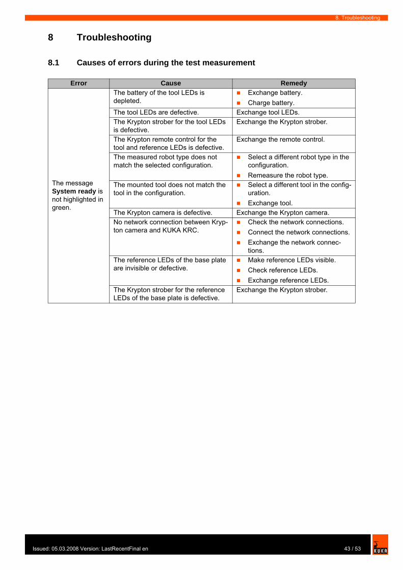
8.1 Causes of errors during the test measurement
Error Cause Remedy
The message System ready is not highlighted in green.
The battery of the tool LEDs is depleted.
Exchange battery.Charge battery.
The tool LEDs are defective. Exchange tool LEDs.The Krypton strober for the tool LEDs is defective.
Exchange the Krypton strober.
The Krypton remote control for the tool and reference LEDs is defective.
Exchange the remote control.
The measured robot type does not match the selected configuration.
Select a different robot type in the configuration.Remeasure the robot type.
The mounted tool does not match the tool in the configuration.
Select a different tool in the config-uration.Exchange tool.
The Krypton camera is defective. Exchange the Krypton camera.No network connection between Kryp-ton camera and KUKA KRC.
Check the network connections.Connect the network connections.Exchange the network connec-tions.
The reference LEDs of the base plate are invisible or defective.
Make reference LEDs visible.Check reference LEDs.Exchange reference LEDs.
The Krypton strober for the reference LEDs of the base plate is defective.
Exchange the Krypton strober.
43 / 53ed: 05.03.2008 Version: LastRecentFinal en

KUKA.XRob RCS
44 / 53 Issued: 05.03.2008 Version: LastRecentFinal en

Issu
9. KUKA Service
9 KUKA Service
9.1 Requesting support
Introduction The KUKA Robot Group documentation offers information on operation and provides assistance with troubleshooting. For further assistance, please con-tact your local KUKA subsidiary.
Information The following information is required for processing a support request:
Model and serial number of the robotModel and serial number of the controllerModel and serial number of the linear unit (if applicable)Version of the KUKA System SoftwareOptional software or modificationsArchive of the softwareApplication usedAny external axes usedDescription of the problem, duration and frequency of the fault
9.2 KUKA Customer Support
Availability KUKA Customer Support is available in many countries. Please do not hesi-tate to contact us if you have any questions.
Argentina Ruben Costantini S.A. (Agency)Luis Angel Huergo 13 20Parque Industrial2400 San Francisco (CBA)ArgentinaTel. +54 3564 421033Fax +54 3564 [email protected]
Australia Marand Precision Engineering Pty. Ltd. (Agency)153 Keys RoadMoorabbinVictoria 31 89AustraliaTel. +61 3 8552-0600Fax +61 3 [email protected]
Faults leading to production downtime are to be reported to the local KUKA subsidiary within one hour of their occurrence.
45 / 53ed: 05.03.2008 Version: LastRecentFinal en

KUKA.XRob RCS
Austria KUKA Roboter GmbHVertriebsbüro ÖsterreichRegensburger Strasse 9/14020 LinzAustriaTel. +43 732 784752Fax +43 732 [email protected]
Belgium KUKA Automatisering + Robots N.V.Centrum Zuid 10313530 HouthalenBelgiumTel. +32 11 516160Fax +32 11 [email protected]
Brazil KUKA Roboter do Brasil Ltda.Avenida Franz Liszt, 80Parque Novo MundoJd. GuançãCEP 02151 900 São PauloSP BrazilTel. +55 11 69844900Fax +55 11 [email protected]
Chile Robotec S.A. (Agency)Santiago de ChileChileTel. +56 2 331-5951Fax +56 2 [email protected]
China KUKA Flexible Manufacturing Equipment (Shanghai) Co., Ltd.Shanghai Qingpu Industrial ZoneNo. 502 Tianying Rd.201712 ShanghaiP.R. ChinaTel. +86 21 5922-8652Fax +86 21 [email protected]
46 / 53 Issued: 05.03.2008 Version: LastRecentFinal en
Issu
9. KUKA Service
France KUKA Automatisme + Robotique SASTechvallée6 Avenue du Parc91140 Villebon s/YvetteFranceTel. +33 1 6931-6600Fax +33 1 [email protected]
Germany KUKA Roboter GmbHBlücherstr. 14486165 AugsburgGermanyTel. +49 821 797-4000Fax +49 821 [email protected]
Hungary KUKA Robotics Hungaria Kft.Fö út 1402335 TaksonyHungaryTel. +36 24 501609Fax +36 24 [email protected]
India KUKA Robotics, Private Limited621 Galleria TowersDLF Phase IV122 002 GurgaonHaryanaIndiaTel. +91 124 [email protected]
Italy KUKA Roboter Italia S.p.A.Via Pavia 9/a - int.610098 Rivoli (TO)ItalyTel. +39 011 959-5013Fax +39 011 [email protected]
47 / 53ed: 05.03.2008 Version: LastRecentFinal en

KUKA.XRob RCS
Korea KUKA Robot Automation Korea Co. Ltd.4 Ba 806 Sihwa Ind. ComplexSung-Gok Dong, Ansan CityKyunggi Do425-110KoreaTel. +82 31 496-9937 or -9938Fax +82 31 [email protected]
Malaysia KUKA Robot Automation Sdn BhdSouth East Asia Regional OfficeNo. 24, Jalan TPP 1/10Taman Industri Puchong47100 PuchongSelangorMalaysiaTel. +60 3 8061-0613 or -0614Fax +60 3 [email protected]
Mexico KUKA de Mexico S. de R.L. de C.V.Rio San Joaquin #339, Local 5Colonia Pensil SurC.P. 11490 Mexico D.F.MexicoTel. +52 55 5203-8407Fax +52 55 [email protected]
Norway KUKA Sveiseanlegg + RoboterBryggeveien 92821 GjövikNorwayTel. +47 61 133422Fax +47 61 [email protected]
Portugal KUKA Sistemas de Automatización S.A.Rua do Alto da Guerra n° 50Armazém 042910 011 SetúbalPortugalTel. +351 265 729780Fax +351 265 [email protected]
48 / 53 Issued: 05.03.2008 Version: LastRecentFinal en
Issu
9. KUKA Service
Russia KUKA-VAZ EngineeringJushnoje Chaussee, 36 VAZ, PTO445633 TogliattiRussiaTel. +7 8482 391249 or 370564Fax +7 8482 [email protected]
South Africa Jendamark Automation LTD (Agency)76a York RoadNorth End6000 Port ElizabethSouth AfricaTel. +27 41 391 4700Fax +27 41 373 3869www.jendamark.co.za
Spain KUKA Sistemas de Automatización S.A.Pol. IndustrialTorrent de la PasteraCarrer del Bages s/n08800 Vilanova i la Geltrú (Barcelona)SpainTel. +34 93 814-2353Fax +34 93 [email protected]
Sweden KUKA Svetsanläggningar + Robotar ABA. Odhners gata 15421 30 Västra FrölundaSwedenTel. +46 31 7266-200Fax +46 31 [email protected]
Switzerland KUKA Roboter Schweiz AGRiedstr. 78953 DietikonSwitzerlandTel. +41 44 74490-90Fax +41 44 [email protected]
49 / 53ed: 05.03.2008 Version: LastRecentFinal en

KUKA.XRob RCS
Taiwan KUKA Robot Automation Taiwan Co. Ltd.136, Section 2, Huanjung E. RoadJungli City, TaoyuanTaiwan 320Tel. +886 3 4371902Fax +886 3 [email protected]
Thailand KUKA Robot Automation (M)SdnBhdThailand Officec/o Maccall System Co. Ltd.49/9-10 Soi Kingkaew 30 Kingkaew RoadTt. Rachatheva, A. BangpliSamutprakarn10540 ThailandTel. +66 2 7502737Fax +66 2 [email protected]
UK KUKA Automation + RoboticsHereward RiseHalesowenB62 8ANUKTel. +44 121 585-0800Fax +44 121 [email protected]
USA KUKA Robotics Corp.22500 Key DriveClinton Township48036 MichiganUSATel. +1 866 8735852Fax +1 586 [email protected]
50 / 53 Issued: 05.03.2008 Version: LastRecentFinal en
Issu
Index
Index
AAbsolute calibration 35
BBase data, editing 24Base data, entering 19
CCamera frame 6Center of gravity 18Configuration 15Configuration file XROBCONFIG.XML 27Configuration overview 15Creating a new configuration 25Creating a new hole pattern 21
DDatabase configurator, installing 12Database configurator, opening 15Database configurator, uninstalling 12Database, installing 12DB 6Documentation, robot system 5
EEditing data 23Entering data in the database configurator 16Entering pose data 22Entering robot data 21Entering robot type data 20Error messages 39Event Viewer 39
FFunctional principle 7
HHD 6Hole pattern 6
IInstallation 11Installation, overview 11Installing Microsoft SQL Server Desktop Engine 11Installing MSDE 11Introduction 5
KKnowledge, required 5Krypton computer 6Krypton strober 6KUKA Customer Support 45KUKA XRob RCS, overview 7
LLoad data, editing 23
Load data, entering 17
MMass 18Mass moments of inertia 18Messages 39Microsoft SQL Server Desktop Engine, uninstall-ing 12Modifying a configuration 27MSDE, uninstalling 12
OOperation 31Overall load 17
PPID data 6Pose data, editing 24Product description 7
RRCS 6RDC 6Robot data, editing 24Robot type data, editing 24Robot types, configuring 25
SSafety 9Safety instructions 5Saving settings 16Selecting a configuration 26Service, KUKA Roboter 45Support request 45System requirements 11
TTarget group 5Terms used 6Tool data, editing 23Tool data, entering 16Tool LEDs 6Tool locating holes 6Training program 5Troubleshooting 43
WWarnings 5Wizard 31, 35Wizard, installing 13Wizard, re-installing 13Wizard, uninstalling 13
XX-Rob 6XRob database, uninstalling 12
51 / 53ed: 05.03.2008 Version: LastRecentFinal en

KUKA.XRob RCS
ZZero mastering 31Zero mastering for KR spot and KR 5 33
52 / 53 Issued: 05.03.2008 Version: LastRecentFinal en

53 / 53Issued: 05.03.2008 Version: LastRecentFinal en


![[Rcs Iot] Rcs-e v1-2- Joyn](https://img.pdfslide.us/doc/110x75/577cd0231a28ab9e78917fbc/rcs-iot-rcs-e-v1-2-joyn.jpg)


![[XLS] OrderForm_v21_11_2014.xls · Web viewDate Drivers Database Tendering BOM Change Log Master Text Configurator Cortec Disclaimer Contacts Feuil4.CORTEC_CHECK_QuandClic Input_Area](https://img.pdfslide.us/doc/110x75/5abbb4487f8b9a76038d09ad/xls-orderformv21112014xlsweb-viewdate-drivers-database-tendering-bom-change.jpg)