Embed Size (px)
Citation preview

KUKA System Technology
KUKA.OPC Server 4.1
For KUKA System Software 8.2 and 8.3
KUKA Roboter GmbH
Issued: 20.02.2013
Version: KST OPC Server 4.1 V2 en (PDF)

KUKA.OPC Server 4.1
2 / 53 Issued: 20.02.2013 Version: KST OPC Server 4.1 V2 en (PDF)
© Copyright 2013
KUKA Roboter GmbH
Zugspitzstraße 140
D-86165 Augsburg
Germany
This documentation or excerpts therefrom may not be reproduced or disclosed to third parties without the express permission of KUKA Roboter GmbH.
Other functions not described in this documentation may be operable in the controller. The user has no claims to these functions, however, in the case of a replacement or service work.
We have checked the content of this documentation for conformity with the hardware and software described. Nevertheless, discrepancies cannot be precluded, for which reason we are not able to guarantee total conformity. The information in this documentation is checked on a regular basis, how-ever, and necessary corrections will be incorporated in the subsequent edition.
Subject to technical alterations without an effect on the function.
Translation of the original documentation
KIM-PS5-DOC
Publication: Pub KST OPC Server 4.1 (PDF) en
Bookstructure: KST OPC Server 4.1 V1.1
Version: KST OPC Server 4.1 V2 en (PDF)

Contents
Contents
1 Introduction .................................................................................................. 5
1.1 Target group .............................................................................................................. 5
1.2 Industrial robot documentation ................................................................................... 5
1.3 Representation of warnings and notes ...................................................................... 5
1.4 Terms used ................................................................................................................ 6
1.5 Trademarks ................................................................................................................ 7
2 Product description ..................................................................................... 9
2.1 Overview of KUKA.OPC Server ................................................................................. 9
2.2 Reading and writing industrial robot variables ........................................................... 11
3 Safety ............................................................................................................ 13
3.1 Safety measures for “single point of control” ............................................................. 13
4 Installation ................................................................................................... 15
4.1 System requirements ................................................................................................. 15
4.2 Installing or updating KUKA.OPC Server ................................................................... 15
4.3 Uninstalling KUKA.OPC Server ................................................................................. 15
5 Operation ...................................................................................................... 17
5.1 Starting the OPC server manually ............................................................................. 17
5.2 Connecting an OPC DA client to the OPC server ...................................................... 17
5.3 Connecting an OPC XML DA client to the OPC server ............................................. 18
6 Configuration for OPC clients .................................................................... 21
6.1 Configuration for OPC XML DA clients ...................................................................... 21
6.2 Configuration for OPC DA clients .............................................................................. 21
6.3 Configuring global DCOM settings ............................................................................. 21
6.3.1 Users and user groups ......................................................................................... 22
6.3.2 Default Properties tab ........................................................................................... 23
6.3.3 COM Security tab ................................................................................................. 24
6.3.3.1 Assigning access permissions .............................................................................. 24
6.3.3.2 Assigning launch and activation permissions ....................................................... 25
6.3.4 Default Protocols tab ............................................................................................ 27
6.3.5 DCOM settings for “OpcEnum” and “KUKA OPC Server” .................................... 29
6.3.5.1 Changing the “KUKA OPC Server Properties” in the DCOM configuration .......... 29
6.3.5.2 Changing the “OpcEnum Properties” in the DCOM configuration ........................ 30
6.4 Configuring the KUKA Line Interface (KLI) ................................................................ 31
6.5 Declaring the OPC server in the Window system directory ....................................... 32
7 Configuring the OPC server ....................................................................... 33
7.1 “OPC configuration” user interface ............................................................................ 33
7.1.1 Creating OPC items .............................................................................................. 34
7.1.2 Changing OPC items ............................................................................................ 34
7.1.3 Deleting OPC items .............................................................................................. 35
7.2 Configuration parameters .......................................................................................... 35
7.2.1 Configuration parameters: “KRC variables” .......................................................... 35
7.2.2 Configuration parameters: “Proxies” ..................................................................... 36
3 / 53Issued: 20.02.2013 Version: KST OPC Server 4.1 V2 en (PDF)

4 / 53
KUKA.OPC Server 4.1
7.2.3 Configuration parameters: “Messages” ................................................................ 36
7.2.4 Configuration parameters: “Registry” ................................................................... 37
7.3 Example configurations for communication with OPC ............................................... 38
7.3.1 Grouping variables ............................................................................................... 38
7.3.2 Serial data transfer ............................................................................................... 40
8 KUKA Service ............................................................................................... 43
8.1 Requesting support ................................................................................................... 43
8.2 KUKA Customer Support ........................................................................................... 43
Index ............................................................................................................. 51
Issued: 20.02.2013 Version: KST OPC Server 4.1 V2 en (PDF)

1 Introduction
1 Introduction
1.1 Target group
This documentation is aimed at users with the following knowledge and skills:
Advanced knowledge of the robot controller system
Advanced knowledge of Windows
Advanced knowledge of network connections
1.2 Industrial robot documentation
The industrial robot documentation consists of the following parts:
Documentation for the manipulator
Documentation for the robot controller
Operating and programming instructions for the KUKA System Software
Documentation relating to options and accessories
Parts catalog on storage medium
Each of these sets of instructions is a separate document.
1.3 Representation of warnings and notes
Safety These warnings are relevant to safety and must be observed.
This warning draws attention to procedures which serve to prevent or remedy emergencies or malfunctions:
Notes These hints serve to make your work easier or contain references to further information.
For optimal use of our products, we recommend that our customers take part in a course of training at KUKA College. Information about the training program can be found at www.kuka.com or can be ob-
tained directly from our subsidiaries.
These warnings mean that it is certain or highly probable that death or severe injuries will occur, if no precautions
are taken.
These warnings mean that death or severe injuries may occur, if no precautions are taken.
These warnings mean that minor injuries may occur, if no precautions are taken.
These warnings mean that damage to property may oc-cur, if no precautions are taken.
These warnings contain references to safety-relevant information or general safety measures. These warnings do not refer to individual hazards or individual pre-
cautionary measures.
Procedures marked with this warning must be followed exactly.
5 / 53Issued: 20.02.2013 Version: KST OPC Server 4.1 V2 en (PDF)

6 / 53
KUKA.OPC Server 4.1
1.4 Terms used
Tip to make your work easier or reference to further information.
Term Description
ACL Access Control List
Access control lists are used to control access rights, e.g. for access to files and programs in operating sys-tems.
DCOM Distributed Component Object Model
Protocol for direct communication of software compo-nents via a network. DCOM is a component of the Win-dows operating system.
KLI Line bus for the integration of the system in the cus-tomer network (KUKA Line Interface)
The KLI is the Ethernet interface of the robot controller for external communication.
KR C KUKA Robot Controller
CRR Controlled Robot Retraction
CRR is an operating mode only available when KUKA.SafeOperation or KUKA.SafeRangeMonitoring is used. If the robot has violated a monitoring function and been stopped by the safety controller, it can only be moved out of the violated area in CRR mode.
KUKA Cross Interface between the real-time operating system VxWorks and the Windows operating system of the KUKA System Software
KUKA smartHMI User interface of the KUKA System Software (KUKA smart Human-Machine Interface)
KUKA smart-PAD
Teach pendant for the industrial robot
OLE Object Link Embedding
Object system and protocol that enables the interaction of different applications within a Windows environment. The objects can be linked or embedded in a document.
OPC OLE for Process Control
Standardized software interface for data exchange between applications within a Windows environment. OPC uses the DCOM protocol.
OPC client An OPC client accesses the data made available by an OPC server.
OPC DA Specification for transferring real-time values via OPC (DCOM-based)
OPC XML-DA Specification for XML-based transfer of real-time val-ues (DCOM-independent)
OPC item An OPC item maps a real process variable. A process variable is an element of the address space of the OPC server, e.g. the input module of a PLC.
Issued: 20.02.2013 Version: KST OPC Server 4.1 V2 en (PDF)

1 Introduction
1.5 Trademarks
InTouch is a trademark of Wonderware GmbH.
Mac Os is a trademark of Apple Inc.
Softing OPC Toolbox Demo Client is a trademark of Softing AG.
VxWorks is a trademark of Wind River Systems Inc.
Windows is a trademark of Microsoft Corporation.
Item ID An OPC item is identified by its item ID. The item ID is the defined name of the OPC item that must be unique in the address space of the OPC server.
OpcEnum Service program that can be used by an OPC client to poll and display the OPC servers installed on a server computer.
Polling
Event
Polling types for reading a variable (OPC item)
With “Polling”, the state or value of a variable is polled and updated cyclically (synchronous read-ing).
With “Event”, the state or value of a variable is polled and updated when this changes (event-de-pendent reading).
SPOC Single Point of Control
PLC Programmable Logic Controller
The PLC is a module for higher-level control tasks in a plant bus system.
Subnet Subnetwork in the Internet Protocol (IP)
TCP/IP Transmission Control Protocol
Protocol of the data exchange between devices of a network. TCP constitutes a virtual channel between two sockets in a network connection. Data can be transmitted on this channel in both directions.
IP Internet Protocol
The Internet protocol is used to define subnetworks by means of physical MAC addresses.
URL Uniform Resource Locator
URLs identify and locate a resource via the access method to be used, eg. the network protocol HTTP, and the location of the resource in the network.
VxWorks Real-time operating system
Term Description
7 / 53Issued: 20.02.2013 Version: KST OPC Server 4.1 V2 en (PDF)

8 / 53
KUKA.OPC Server 4.1
Issued: 20.02.2013 Version: KST OPC Server 4.1 V2 en (PDF)

2 Product description
2 Product description
2.1 Overview of KUKA.OPC Server
KUKA.OPC Server is an add-on technology package. The OPC server makes it possible to communicate and exchange data with the robot controller from a local or remote OPC client.
Functions Reading and writing of system and program variables of the industrial ro-bot
Reading of robot controller messages
Reading of keys from the registration database
Reading of variables from other OPC servers via the proxy interface
Communication
without OPC
Without OPC, 2 machines or applications must know each other’s communi-cations options in order to be able to exchange data.
Communication
with OPC
With OPC, it suffices to configure an OPC-compliant driver for each machine or application. All programs that can request data as OPC clients work togeth-er with the OPC server. This simplifies and standardizes access.
KUKA.OPC Server uses the network protocol TCP/IP. The network connec-tion is established via the Windows interface of the KUKA Line Interface (KLI) of the robot controller.
Fig. 2-1: Communication without OPC
It is not possible to browse to the OPC server in Windows.
9 / 53Issued: 20.02.2013 Version: KST OPC Server 4.1 V2 en (PDF)
10 / 53
KUKA.OPC Server 4.1
Areas of appli-
cation
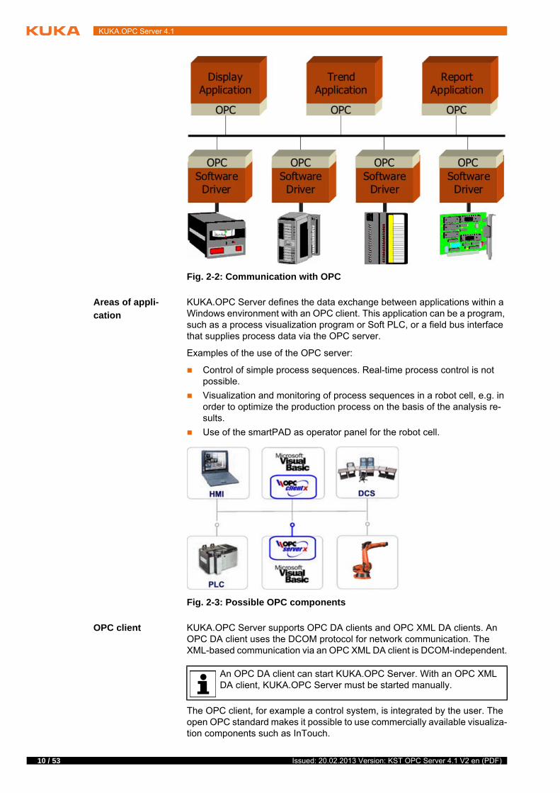
KUKA.OPC Server defines the data exchange between applications within a Windows environment with an OPC client. This application can be a program, such as a process visualization program or Soft PLC, or a field bus interface that supplies process data via the OPC server.
Examples of the use of the OPC server:
Control of simple process sequences. Real-time process control is not possible.
Visualization and monitoring of process sequences in a robot cell, e.g. in order to optimize the production process on the basis of the analysis re-sults.
Use of the smartPAD as operator panel for the robot cell.
OPC client KUKA.OPC Server supports OPC DA clients and OPC XML DA clients. An OPC DA client uses the DCOM protocol for network communication. The XML-based communication via an OPC XML DA client is DCOM-independent.
The OPC client, for example a control system, is integrated by the user. The open OPC standard makes it possible to use commercially available visualiza-tion components such as InTouch.
Fig. 2-2: Communication with OPC
Fig. 2-3: Possible OPC components
An OPC DA client can start KUKA.OPC Server. With an OPC XML DA client, KUKA.OPC Server must be started manually.
Issued: 20.02.2013 Version: KST OPC Server 4.1 V2 en (PDF)

2 Product description
The scope of supply of KUKA.OPC Server includes the source code for vari-ous example clients, as well as for the Softing OPC Toolbox Demo Client.
The source code of the example clients is located in the Tool.zip archive under Tools on the CD-ROM. The source code can be used as a template to create your own OPC clients:
C# client (MS Visual C#)
C++ client (MS Visual C++)
VB client (MS Visual Basic)
The Softing Demo Client is located in the folder Tools\Demo-Client. The Demo Client can be used to test the communication with the OPC Server. The following specifications are supported:
Data Access V1.0, V2.0 and V3.0 (DA)
XML Data Access V1.0 (XML DA)
User adminis-
tration
KUKA.OPC Server does not include any user administration. If required, this must be integrated with the OPC client by the user.
2.2 Reading and writing industrial robot variables
Access functions When it comes to reading and writing system and program variables of the in-dustrial robot, a basic distinction is made between synchronous and event-de-pendent access to the VxWorks real-time operating system.
Synchronous reading and writing are implemented using the Cross func-tions ShowVar and SetVar. A variable is updated at a defined interval.
Event-dependent reading is implemented using the Cross function SetIn-fo. The OPC item is read via SetInfo whenever the value of a variable changes.
The number of event-dependent access operations is limited by the kernel system (max. 40). Once the maximum number of SetInfos has been reached, all further OPC items are read synchronously.
The Softing Demo Client is not SPOC-compliant and must not be used in a system. The Softing Demo Client
must only be used to test whether the client and server are communicating.
The OPC server can be used with write access to modify programs, outputs or other parameters of the robot con-
troller, without this being noticed by any persons located inside the system.If the OPC server is used, safety measures must be taken to ensure com-plete implementation of the principle of “single point of control” (SPOC). It must be ensured that potentially hazardous signals (e.g. the opening/closing of a gun) can only be executed if AUT or AUT EXT mode is set and the safety gate is closed. For this, the variables $USER_SAF and $SPOC_MOTION_ENABLE must be polled accordingly.Failure to implement these safety measures may result in death to persons, severe injuries or considerable damage to property.
In AUT EXT mode, the setting of outputs is not possible by default.
A module that is connected via SetInfo cannot be edited or deleted.
11 / 53Issued: 20.02.2013 Version: KST OPC Server 4.1 V2 en (PDF)

12 / 53
KUKA.OPC Server 4.1
Configuration
tips
The update interval of the OPC server cannot be changed by the OPC client and is dependent on the following factors:
Number of variables (OPC items) created
During reading and writing, the variables are transferred one by one in data packets via the KUKA Cross interface. The time required for the com-plete transfer of the variables is roughly proportional to the number of the variables.
To reduce the transfer time, it is recommended to group variables, e.g. several Boolean variables can be grouped together as an integer variable, or several inputs or outputs as a signal.
Variable type
Complex variables such as data structures or arrays are broken down into a number of data packets. This increases the transmission time.
If only one array element needs to read, e.g. the input $IN[1], it is recom-mended that only this element is polled and not the entire array, in order to reduce the transmission time. To read several inputs, it is appropriate to poll the complete $IN[] array.
Polling type
Polling: Cyclically via ShowVar (synchronous reading)
Event: Acyclically via SetInfo (event-dependent reading)
Polling (ShowVar) generally causes more data traffic on the KUKA Cross interface than Event (SetInfo). The reason for this is that the “Polling” type entails regular polling, irrespective of whether the state or value of the OPC item has changed.
If SetInfo is set for an OPC item that changes its value frequently, the data traffic may be just as high as with ShowVar. This is the case when reading the variable $TIMER[x], for example.
Issued: 20.02.2013 Version: KST OPC Server 4.1 V2 en (PDF)

3 Safety
3 Safety
This documentation contains safety instructions which refer specifically to the software described here.
The fundamental safety information for the industrial robot can be found in the “Safety” chapter of the Operating and Programming Instructions for System In-tegrators or the Operating and Programming Instructions for End Users.
3.1 Safety measures for “single point of control”
Overview If certain components in the industrial robot are operated, safety measures must be taken to ensure complete implementation of the principle of “single point of control” (SPOC).
Components:
Submit interpreter
PLC
OPC Server
Remote control tools
Tools for configuration of bus systems with online functionality
KUKA.RobotSensorInterface
Since only the system integrator knows the safe states of actuators in the pe-riphery of the robot controller, it is his task to set these actuators to a safe state, e.g. in the event of an EMERGENCY STOP.
T1, T2, CRR In the test modes T1, T2 and CRR, the components referred to above may only access the industrial robot if the following signals have the following states:
The “Safety” chapter in the operating and programming instructions must be observed. It is particularly important
to observe those safety measures which are required to ensure complete im-plementation of the principle of “single point of control” (SPOC).It must be ensured that potentially hazardous signals (e.g. the opening/clos-ing of a gun) can only be executed if AUT or AUT EXT mode is set and the safety gate is closed. For this, the variables $USER_SAF and $SPOC_MOTION_ENABLE must be polled accordingly.Failure to implement these safety measures may result in death to persons, severe injuries or considerable damage to property.
DA enables many clients to connect to the OPC server and manipulate the robot controller. To reduce the risk of
unauthorized access to the robot controller, it is recommended to limit the number of authorized users to the necessary minimum in the DCOM safety settings.
XML DA enables many clients to connect to the OPC server and manipulate the robot controller. To reduce the
risk of unauthorized access to the robot controller, it is recommended to limit the number of authorized users to a few devices in a subnet. The client and server computers must be present in the subnet.
The implementation of additional safety measures may be required. This must be clarified for each specific application; this is the respon-sibility of the system integrator, programmer or user of the system.
13 / 53Issued: 20.02.2013 Version: KST OPC Server 4.1 V2 en (PDF)

14 / 53
KUKA.OPC Server 4.1
Submit inter-
preter, PLC
If motions, (e.g. drives or grippers) are controlled with the submit interpreter or the PLC via the I/O system, and if they are not safeguarded by other means, then this control will take effect even in T1, T2 and CRR modes or while an EMERGENCY STOP is active.
If variables that affect the robot motion (e.g. override) are modified with the submit interpreter or the PLC, this takes effect even in T1, T2 and CRR modes or while an EMERGENCY STOP is active.
Safety measures:
In T1, T2 and CRR, the system variable $OV_PRO must not be written to by the submit interpreter or the PLC.
Do not modify safety-relevant signals and variables (e.g. operating mode, EMERGENCY STOP, safety gate contact) via the submit interpreter or PLC.
If modifications are nonetheless required, all safety-relevant signals and variables must be linked in such a way that they cannot be set to a dan-gerous state by the submit interpreter or PLC.
OPC server,
remote control
tools
These components can be used with write access to modify programs, outputs or other parameters of the robot controller, without this being noticed by any persons located inside the system.
Safety measures:
KUKA stipulates that these components are to be used exclusively for di-agnosis and visualization.
Programs, outputs or other parameters of the robot controller must not be modified using these components.
If these components are used, outputs that could cause a hazard must be determined in a risk assessment. These outputs must be designed in such a way that they cannot be set without being enabled. This can be done us-ing an external enabling device, for example.
Tools for configu-
ration of bus
systems
If these components have an online functionality, they can be used with write access to modify programs, outputs or other parameters of the robot control-ler, without this being noticed by any persons located inside the system.
WorkVisual from KUKA
Tools from other manufacturers
Safety measures:
In the test modes, programs, outputs or other parameters of the robot con-troller must not be modified using these components.
Signal State required for SPOC
$USER_SAF TRUE
$SPOC_MOTION_ENABLE TRUE
Issued: 20.02.2013 Version: KST OPC Server 4.1 V2 en (PDF)

4 Installation
4 Installation
4.1 System requirements
Hardware KR C4
Software Robot controller:
KUKA System Software 8.2 and 8.3
External computer:
Operating system Windows XP, Windows XPe or Windows 7 for OPC DA clients
4.2 Installing or updating KUKA.OPC Server
Preparation Copy the software from the CD to the KUKA.USBData stick.
Precondition “Expert” user group
Procedure 1. Plug in USB stick.
2. In the main menu, select Start-up > Additional software.
3. Click on New software. If a software package that is on the USB stick is not displayed, click on Refresh.
4. Mark the entry KUKA.OPC Server and click on Install. Reply to the re-quest for confirmation with Yes. The files are copied onto the hard drive.
5. Remove USB stick.
6. It may be necessary to reboot the controller, depending on the additional software. In this case, a corresponding prompt is displayed. Confirm with OK and reboot the robot controller. Installation is resumed and completed.
LOG file A LOG file is created under C:\KRC\ROBOTER\LOG.
4.3 Uninstalling KUKA.OPC Server
Precondition “Expert” user group
Procedure 1. In the main menu, select Start-up > Additional software. All additional programs installed are displayed.
2. Mark the entry KUKA.OPC Server and click on Uninstall. Reply to the re-quest for confirmation with Yes. Uninstallation is prepared.
3. Reboot the robot controller. Uninstallation is resumed and completed.
OPC XML DA clients are DCOM-independent and can also be oper-ated on other operating systems than the Windows operating system, e.g. Mac OS or Linux.
It is advisable to archive all relevant data before updating a software package.
Only the KUKA.USB data stick may be used. Data may be lost or modified if any other USB stick is used.
It is advisable to archive all relevant data before uninstalling a soft-ware package.
15 / 53Issued: 20.02.2013 Version: KST OPC Server 4.1 V2 en (PDF)

16 / 53
KUKA.OPC Server 4.1
LOG file A LOG file is created under C:\KRC\ROBOTER\LOG.
Issued: 20.02.2013 Version: KST OPC Server 4.1 V2 en (PDF)

5 Operation
5 Operation
5.1 Starting the OPC server manually
Procedure 1. Select Configuration > OPC configuration from the main menu. The OPC configuration window is opened.
2. Select the Diagnostic screen and click on Start Server/ Connect Server.
Description The OPC server is started as an application and the connection is established with the server. Once the connection is established, the KRC OPCServer win-dow is opened, displaying the current status of the server.
The following buttons are available:
5.2 Connecting an OPC DA client to the OPC server
Precondition The robot controller is running.
The IP address of the active Windows interface is known.
The DCOM settings on the server and client computers are configured.
(>>> 6.2 "Configuration for OPC DA clients" Page 21)
Only if a remote client is being used:
The Windows user is logged in to the client and server computer with the same user name and password. If this is not the case, further DCOM settings are required to declare the user in DCOM.
If the OPC configuration window is closed via the Close symbol, the connection to the OPC server is terminated and the KRC OPCServer for status display is closed. This does not stop the OPC server.
Fig. 5-1: Starting the OPC server manually
Button Description
Start Server/ Connect Serv-er
Starts the OPC server as an application and establishes the connection to the OPC server in order to poll the sta-tus of the server. (LED lights up green - status running.) If the server has already been started, the connection to the server is established automatically.
The button is only active if the server has not been start-ed. (LED lights up red - status unknown)
17 / 53Issued: 20.02.2013 Version: KST OPC Server 4.1 V2 en (PDF)

18 / 53
KUKA.OPC Server 4.1
Port 135 and the dynamic ports for communication via DCOM are ac-tivated for TCP on the Windows interface of the KLI.
(>>> 6.4 "Configuring the KUKA Line Interface (KLI)" Page 31)
Procedure Enter the following URL: opcda://IP address/KUKASrvr.DA.1
The OPC client connects to the OPC server. If the OPC server is not yet running, it is started by the OPC client.
Example
5.3 Connecting an OPC XML DA client to the OPC server
Precondition The robot controller is running.
The IP address of the active Windows interface is known.
Only if a remote client is being used:
Port 8081 is activated for TCP on the Windows interface of the KLI.
(>>> 6.4 "Configuring the KUKA Line Interface (KLI)" Page 31)
Procedure 1. Start the OPC server manually.
2. Enter the following URL: http://IP address:8081/DA
The OPC client connects to the OPC server.
An OPC server that has been started by a client is stopped automat-ically when the last connected OPC client is closed.
Fig. 5-2: Softing Demo Client – URL for OPC DA
Issued: 20.02.2013 Version: KST OPC Server 4.1 V2 en (PDF)

5 Operation
Example
Fig. 5-3: Softing Demo Client – URL for OPC XML DA
19 / 53Issued: 20.02.2013 Version: KST OPC Server 4.1 V2 en (PDF)

20 / 53
KUKA.OPC Server 4.1
Issued: 20.02.2013 Version: KST OPC Server 4.1 V2 en (PDF)

6 Configuration for OPC clients
6 Configuration for OPC clients
6.1 Configuration for OPC XML DA clients
Overview
6.2 Configuration for OPC DA clients
Overview
6.3 Configuring global DCOM settings
Precondition “Expert” user group
Administrator privileges on the Windows user interface
Procedure 1. In the main menu, select Start-up > Service > Minimize HMI.
2. In the Windows Start menu, select Run….
Step Description
1 Activate port 8081 for TCP on the Windows interface of the KLI.
(>>> 6.4 "Configuring the KUKA Line Interface (KLI)" Page 31)
2 Recommended if remote clients access the OPC server: Con-figure the network so that the number of users that can connect to the OPC server as a client is limited to the necessary mini-mum.
Step Description
1 Configure global DCOM settings.
Activate DCOM on the server and client computers.
Define users or user groups that are authorized to start or use DCOM applications.
If remote clients access the OPC server: Define the port range for DCOM communication on the server computer.
2 If remote clients access the OPC server: In the DCOM configu-ration, assign the Interactive user the right to start the OPC server.
3 If necessary, change the properties of OpcEnum in the DCOM configuration.
4 Activate port 135 and the dynamic ports for communication via DCOM for TCP on the Windows interface of the KLI.
(>>> 6.4 "Configuring the KUKA Line Interface (KLI)" Page 31)
5 In the Windows system directory of the client computer, declare the network names and IP addresses of the OPC servers accessed by a remote client.
(>>> 6.5 "Declaring the OPC server in the Window system directory" Page 32)
The configuration of the DCOM settings is described here for Win-dows XPe SP3. The procedures and software texts may differ, de-pending on the Windows operating system and the installed Windows
language.
21 / 53Issued: 20.02.2013 Version: KST OPC Server 4.1 V2 en (PDF)

22 / 53
KUKA.OPC Server 4.1
3. In the Open box, enter “DCOMCNFG” and confirm with OK. The Compo-nent Services window opens.
4. Open the Component Services\Computers folder in the tree structure and select the element My Computer.
5. Right-click on My Computer and select Properties. The My Computer Properties window is opened.
6. Make the required settings on the tabs.
(>>> 6.3.2 "Default Properties tab" Page 23)
(>>> 6.3.3 "COM Security tab" Page 24)
(>>> 6.3.4 "Default Protocols tab" Page 27)
7. Save the settings with OK and reboot the PC.
6.3.1 Users and user groups
For operating and configuring OPC servers, the users and user groups spec-ified here are required, at least:
Fig. 6-1: Component Services window
In order to connect to the OPC server, a Windows user must be logged in to the client and server computers with the same user name and password. If this is not the case, further DCOM settings are re-
quired to declare the user in DCOM.
Windows language: German
Windows language: English
Description
Administrator Administrator The Administrator is the default user group. This user group is protected by means of a password.
Note: The password of the default user group should not be changed if at all possible. Changing the password causes the automatic booting of the robot controller to be interrupted by the Window logon.
INTERAKTIV INTERACTIVE Interactive user (= user currently logged on)
SYSTEM SYSTEM User account of the operating system (only used for starting services)
ANONYMOUS-ANMELDUNG
ANONYMOUS LOGON
—
Issued: 20.02.2013 Version: KST OPC Server 4.1 V2 en (PDF)

6 Configuration for OPC clients
6.3.2 Default Properties tab
Description The default safety settings for DCOM are defined here.
The following setting is required:
Enable DCOM (Distributed COM) on this computer (set check mark).
The DCOM protocol must be enabled on the robot controller and on each of the networked computers from which the OPC server is to be accessed.
The following settings are recommended:
Default Authentication Level:
Connect: Authentication is carried out the first time the client access-es the server.
Default Impersonation Level:
Identify: The client can be identified by the server and perform ACL checks.
Depending on the system or application, it may be necessary to add further users or user groups that are authorized to access the OPC server. It must be ensured, however, that the number of authorized
users is limited to the minimum number necessary. The risk of unauthorized access to the robot controller can thus be reduced, if not entirely excluded.
Fig. 6-2: My Computer Properties – Default Properties window
Depending on the system or application, other settings than those recommended here may be required in the default properties for DCOM communication. The DCOM protocol must always be activat-
ed.
23 / 53Issued: 20.02.2013 Version: KST OPC Server 4.1 V2 en (PDF)

24 / 53
KUKA.OPC Server 4.1
6.3.3 COM Security tab
Description The users or user groups that are authorized to start or use DCOM applica-tions are defined here.
The Access, Launch and Activation Permissions must be defined on the robot controller and on each of the networked computers from which the OPC server is to be accessed.
6.3.3.1 Assigning access permissions
Description The following users or user groups must be present, at least:
Administrator
ANONYMOUS LOGON
INTERACTIVE
SYSTEM
For each of these users, Local Access must be activated. If remote clients are to access the OPC server, Remote Access must also be activated for each us-er.
Fig. 6-3: My Computer Properties – COM Security window
Issued: 20.02.2013 Version: KST OPC Server 4.1 V2 en (PDF)
6 Configuration for OPC clients
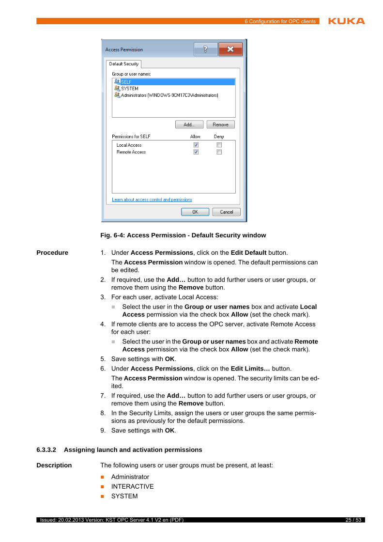
Procedure 1. Under Access Permissions, click on the Edit Default button.
The Access Permission window is opened. The default permissions can be edited.
2. If required, use the Add… button to add further users or user groups, or remove them using the Remove button.
3. For each user, activate Local Access:
Select the user in the Group or user names box and activate Local Access permission via the check box Allow (set the check mark).
4. If remote clients are to access the OPC server, activate Remote Access for each user:
Select the user in the Group or user names box and activate Remote Access permission via the check box Allow (set the check mark).
5. Save settings with OK.
6. Under Access Permissions, click on the Edit Limits… button.
The Access Permission window is opened. The security limits can be ed-ited.
7. If required, use the Add… button to add further users or user groups, or remove them using the Remove button.
8. In the Security Limits, assign the users or user groups the same permis-sions as previously for the default permissions.
9. Save settings with OK.
6.3.3.2 Assigning launch and activation permissions
Description The following users or user groups must be present, at least:
Administrator
INTERACTIVE
SYSTEM
Fig. 6-4: Access Permission - Default Security window
25 / 53Issued: 20.02.2013 Version: KST OPC Server 4.1 V2 en (PDF)

26 / 53
KUKA.OPC Server 4.1
For each of these users, Local Access must be activated. If remote clients are to access the OPC server, Remote Access must also be activated for each us-er.
Procedure 1. Under Launch and Activation Permissions, click on the Edit Default… button.
The window Launch and Activation Permission is opened. The default permissions can be edited.
2. If required, use the Add… button to add further users or user groups, or remove them using the Remove button.
3. For each user, activate Local Access:
Select the user in the Group or user names box and activate Local Launch and Local Activation permissions via the check box Allow (set the check mark).
4. If remote clients are to access the OPC server, activate Remote Access for each user:
Select the user in the Group or user names box and activate Remote Launch and Remote Activation permissions via the check box Allow (set the check mark).
5. Save settings with OK.
6. Under Launch and Activation Permissions, click on the Edit Limits… button.
The Launch Permission window is opened. The security limits can be ed-ited.
7. If required, use the Add… button to add further users or user groups, or remove them using the Remove button.
8. In the Security Limits, assign the users or user groups the same permis-sions as previously for the default permissions.
9. Save settings with OK.
Fig. 6-5: Launch and Activation Permission window
Issued: 20.02.2013 Version: KST OPC Server 4.1 V2 en (PDF)

6 Configuration for OPC clients
6.3.4 Default Protocols tab
Description The network protocol TCP/IP is defined here for DCOM communication, in-cluding the port range in which this communication takes place.
By default, DCOM uses dynamic ports, i.e. communication takes place via a randomly assigned port, which can lie between port 1,024 and 65,534. This port range must be limited, since the ports defined here must be enabled for the TCP protocol on the Windows interface of the KLI. (A maximum total of 40 ports can be enabled on the interface.)
(>>> 6.4 "Configuring the KUKA Line Interface (KLI)" Page 31)
The port range 20,000 … 20,300 is reserved by KUKA for communication with the OPC server. It is recommended to use ports from this range to avoid con-flicts with other DCOM applications.
The number of ports required depends on the expected number of simultane-ous client connections. Overly restricting the number of ports can result in there being insufficient ports available for communication in the event of ac-cess by multiple clients. It must also be considered that it can take 1 to 2 min-utes before a port is available again after an OPC client has terminated its connection with the OPC server. It is therefore not enough to enable the same number of ports as OPC clients. The number of ports must always be at least the number of OPC clients accessing the OPC server, plus a sufficiently large buffer.
Procedure 1. Under DCOM Protocols, select the entry Connection-oriented TCP/IP.
If the port range 20,000 … 20,300 is already used by the customer for other applications, it is recommended to request other KUKA-re-served port ranges from KUKA Roboter GmbH. Faults in the opera-
tion of the OPC server may otherwise result. (>>> 8 "KUKA Service" Page 43)
For stable operation of the OPC server, at least 10 ports are required for most applications. In tests, the best results were achieved with ap-prox. 20 ports.
27 / 53Issued: 20.02.2013 Version: KST OPC Server 4.1 V2 en (PDF)

28 / 53
KUKA.OPC Server 4.1
2. Select the Properties… button. The Properties for COM Internet Ser-vices window is opened.
3. Select the Add… button. The Add port range window is opened.
4. Under Port Ranges, enter the desired port range, e.g. 20100-20110, and confirm with OK.
5. Under Port range assignment and Default dynamic port allocation, ac-tivate the radio button Internet range in each case.
Fig. 6-6: My Computer Properties – Default Protocols window
Fig. 6-7: Properties for COM Internet Services window
Issued: 20.02.2013 Version: KST OPC Server 4.1 V2 en (PDF)

6 Configuration for OPC clients
6. Save settings with OK.
7. Check that the defined port range has been added in the window Proper-ties for COM Internet Services. If the port range is not displayed, enter and save the port range again.
6.3.5 DCOM settings for “OpcEnum” and “KUKA OPC Server”
Overview This section describes the DCOM settings required on the server computer for the services OpcEnum and KUKA OPC Server.
The properties of OpcEnum are preset so that the default settings can be used without changes. This also applies to the properties of KUKA OPC Serv-er, with one exception: the identity of the user who is authorized to start the OPC server as an application must be changed. Only the interactive user is authorized to do this.
6.3.5.1 Changing the “KUKA OPC Server Properties” in the DCOM configuration
Description Every OPC DA client which connects to the OPC server starts it. To ensure that the OPC server is only started once as an application, it must be defined in the DCOM configuration that only the Interactive user may execute the ap-plication.
Precondition “Expert” user group
Administrator privileges on the Windows user interface
Procedure 1. In the main menu, select Start-up > Service > Minimize HMI.
2. In the Windows Start menu, select Run….
3. In the Open box, enter “DCOMCNFG” and confirm with OK. The Compo-nent Services window opens.
4. In the tree structure, open the folder Component Services\Computer\My Computer\DCOM Config.
5. Confirm the DCOM Configuration Warning with Yes.
Tab OpcEnum KUKA OPC Server
General Authentication Level:
None: No authentication is car-ried out.
Authentication Level:
Default: Authentication is carried out the first time an OPC client accesses the OPC server.
Location The applications are only to be executed locally.
The check box Run application on this computer must be activated (check mark is set).
Security The default permissions entered for OpcEnum may be used. It is not necessary to add any more users or assign any permissions.
The default permissions configured in the global DCOM settings (COM Security tab) are inserted here. It is not necessary to add any more users or assign any permissions.
Endpoints The default protocol is used. No other DCOM protocol needs to be added.
Identity OpcEnum is started by default by the user account of the operating system.
The radio button This system account (services only) must be activated.
Only the interactive user may start the OPC server as an application.
The radio button Interactive user must be activated.
29 / 53Issued: 20.02.2013 Version: KST OPC Server 4.1 V2 en (PDF)

30 / 53
KUKA.OPC Server 4.1
6. Select the element KUKA OPC Server and select Action > Properties from the menu. The KUKA OPC Server Properties window is opened.
7. Select the Identity tab and activate the radio button Interactive user.
8. Save the settings with OK and reboot the PC.
6.3.5.2 Changing the “OpcEnum Properties” in the DCOM configuration
Description The service OpcEnum can be used to poll and display the OPC servers that are installed on a server computer. OpcEnum can only be configured in such a way that either all or none of the installed OPC servers are displayed to the user. OpcEnum cannot be used to display only selected OPC servers, e.g. in order to hide safety-critical data sources.
Precondition “Expert” user group
Administrator privileges on the Windows user interface
Procedure 1. In the main menu, select Start-up > Service > Minimize HMI.
Fig. 6-8: DCOM Configuration Warning
Fig. 6-9: KUKA OPC Server Properties - General window
The configuration of OpcEnum is not covered by this documentation. The properties of OpcEnum are preset on the server computer so that the default settings can be used without changes, although the
settings may also be adapted.
Issued: 20.02.2013 Version: KST OPC Server 4.1 V2 en (PDF)

6 Configuration for OPC clients
2. In the Windows Start menu, select Run….
3. In the Open box, enter “DCOMCNFG” and confirm with OK. The Compo-nent Services window opens.
4. In the tree structure, open the folder Component Services\Computer\My Computer\DCOM Config.
5. Confirm the DCOM Configuration Warning with Yes.
6. Select the element OpcEnum and select Action > Properties from the menu. The OpcEnum Properties window is opened.
7. Make the desired settings on the tabs.
8. Save the settings with OK and reboot the PC.
6.4 Configuring the KUKA Line Interface (KLI)
In order for an external PC to be able to connect to the robot controller via the network, the KUKA Line Interface (KLI) of the robot controller must be config-ured accordingly.
Fig. 6-10: DCOM Configuration Warning
Fig. 6-11: OpcEnum Properties - General window
Detailed information about network configuration via the KUKA Line Interface (KLI) of the robot controller is contained in the Operating and Programming Instructions for System Integrators.
31 / 53Issued: 20.02.2013 Version: KST OPC Server 4.1 V2 en (PDF)
32 / 53
KUKA.OPC Server 4.1
The Windows interface is a virtual interface of the KLI. For communication be-tween the OPC client and OPC server, the following ports of the Windows in-terface must be enabled for the TCP protocol:
For XML DA clients:
Port 8081 for XML-based communication
For DA clients:
Port 135 for establishing connections via DCOM
Dynamic ports for communication via DCOM
6.5 Declaring the OPC server in the Window system directory
Description The IP addresses and the network names of the OPC servers accessed by a remote client must be declared in the Windows system directory of the client computer.
Procedure 1. Open the file C:\WINDOWS\system32\drivers\etc\hosts in a text editor.
2. Enter the IP address and network name of the OPC server.
3. Close the file and save the changes.
Example
Each entry must be written on a separate line. The IP address should be in the first column, followed by the corresponding network name. The IP address and network name must be separated by at least one space.
...10.129.221.221 Robi110.129.221.222 Robi210.129.221.223 Robi3
Issued: 20.02.2013 Version: KST OPC Server 4.1 V2 en (PDF)

7 Configuring the OPC server
7 Configuring the OPC server
7.1 “OPC configuration” user interface
Call Select Configuration > OPC configuration from the main menu.
In the user group “User”, the current configuration of the OPC server can be displayed but not edited.
Overview
The following configuration screens are available:
Fig. 7-1: OPC configuration user interface
Item Description
1 Item list
The configured OPC items are displayed here.
The following OPC items are preconfigured by default:
SPOC_MOTION_ENABLE
USER_SAF
The OPC items can be used to poll the signals $USER_SAF and $SPOC_MOTION_ENABLE.
2 Configuration parameters
33 / 53Issued: 20.02.2013 Version: KST OPC Server 4.1 V2 en (PDF)

34 / 53
KUKA.OPC Server 4.1
The following buttons are available. The buttons are not active in the user group “User”:
7.1.1 Creating OPC items
Precondition “Expert” user group
Procedure 1. In the main menu, select Configuration > OPC configuration and then select the desired configuration screen.
2. Click on Add and configure the parameters as required.
3. Click on Save and answer the request for confirmation with Yes. The new-ly created item is saved.
The configuration of the OPC server is applied immediately. The OPC server is automatically closed and all open client connections are terminat-ed.
7.1.2 Changing OPC items
Precondition “Expert” user group
Procedure 1. In the main menu, select Configuration > OPC configuration and then select the desired configuration screen.
2. Select the OPC item in the item list and change the parameters as re-quired.
3. Click on Save and answer the request for confirmation with Yes. The mod-ified item is saved.
The configuration of the OPC server is applied immediately. The OPC server is automatically closed and all open client connections are terminat-ed.
Screen Description
KRC variables OPC items for read and write access to system or pro-gram variables of the industrial robot
(>>> 7.2.1 "Configuration parameters: “KRC vari-ables”" Page 35)
Proxies OPC items for read access to items of other OPC serv-ers in the network
(>>> 7.2.2 "Configuration parameters: “Proxies”" Page 36)
Messages OPC items for read access to messages on the KUKA smartHMI
(>>> 7.2.3 "Configuration parameters: “Messages”" Page 36)
Registry OPC items for read access to Windows operating sys-tem registry database keys on the robot controller
(>>> 7.2.4 "Configuration parameters: “Registry”" Page 37)
Button Description
Add Creates a new OPC item in the item list.
Delete Deletes the selected OPC item from the item list.
Save Saves the configuration of the OPC Server.
The button only becomes active if the configuration is changed.
Issued: 20.02.2013 Version: KST OPC Server 4.1 V2 en (PDF)

7 Configuring the OPC server
7.1.3 Deleting OPC items
Precondition “Expert” user group
Procedure 1. In the main menu, select Configuration > OPC configuration and then select the desired configuration screen.
2. Select an OPC item in the item list, click on Delete and answer the request for confirmation with Yes. The item is deleted from the item list.
3. Click on Save and answer the request for confirmation with Yes. The change is saved.
The configuration of the OPC server is applied immediately. The OPC server is automatically closed and all open client connections are terminat-ed.
7.2 Configuration parameters
7.2.1 Configuration parameters: “KRC variables”
Parameter Description
DA identifier Name of the OPC item (item ID)
The name can be freely chosen and must be unique.
KRL variable Name of the system or program variable
All specified variables can be browsed hierarchically with an OPC client.
Note: The variables that OPC is to access must be globally valid. The syntax of the variables is not monitored and no check is made as to whether the variable exists.
Variable type Data type of the variable
String
Enum
Integer
Real
Boolean
StringArray
IntegerArray
RealArray
BooleanArray
EnumArray
StructArray
Access rights Access rights
Read: Read only (write-protected)
ReadWrite: Read and write
Note: Arrays and structures can only be read.
Access type Polling type for reading the variable (OPC item)
Event: Acyclically via SetInfo (event-dependent reading); max. 40 access operations
Polling: Cyclically via ShowVar (synchronous reading)
Note: A module that is connected via SetInfo cannot be edited or deleted.
35 / 53Issued: 20.02.2013 Version: KST OPC Server 4.1 V2 en (PDF)

36 / 53
KUKA.OPC Server 4.1
7.2.2 Configuration parameters: “Proxies”
7.2.3 Configuration parameters: “Messages”
Parameter Description
DA identifier Name of the OPC item (item ID)
The name can be freely chosen and must be unique.
URL URL of the OPC server in the network
Example:
opcda://XSrv.DA.1
Note: The syntax of the URL is not monitored.
DA Item Name of the OPC item on the OPC server in the network
The name can be structured as follows:
group_name.item_name
A number of OPC items are grouped under a common name, e.g. KRC.IN1, KRC.IN2, KRC.OUT3, etc.
Item_name
Individual OPC item that is not assigned to a group, e.g. TOOL
Variable type Data type of the OPC item on the OPC server in the network
Double
Integer
Bool
String
IntArray
DoubleArray
StringArray
Parameter Description
DA identifier Name of the OPC item (item ID)
The name can be freely chosen and must be unique.
Type of message task Type of message task
Message: The message is generated individually.
MessageArray: The message is output in a message table.
Array size Size of the message table
Default: 10
This parameter is only available for the message type MessageArray.
Issued: 20.02.2013 Version: KST OPC Server 4.1 V2 en (PDF)

7 Configuring the OPC server
7.2.4 Configuration parameters: “Registry”
Message types Select the message type. For this, activate the check box (set the check mark) by clicking on the button in the menu.
To open the menu, click on Message types:
State: Status message
SubState: Message about an acknowledged status message
Quit: Acknowledgement message
Subquit: Message about an acknowledged acknowledgement mes-sage
Dialog: Dialog message
Subdialog: Message about an acknowledged dialog message
XLate: Message is translated.
Info: Notification message
Message elements Select additional elements that are to be displayed together with the mes-sage. For this, activate the check box (set the check mark) by clicking on the button in the menu.
To open the menu, click on Message elements:
Handle: Handle of the message
Type: Message type
Time: Message time
Number: Message number
Sender: Originator of the message
Mode: Currently without function.
Parameter Description
Parameter Description
DA identifier Name of the OPC item (item ID)
Example:
Version of the KR C
The name can be freely chosen and must be unique.
Root Main key
HKEY_CURRENT_USER
HKEY_CLASSES_ROOT
HKEY_LOCAL_MACHINE
HKEY_USERS
HKEY_CURRENT_CONFIG
37 / 53Issued: 20.02.2013 Version: KST OPC Server 4.1 V2 en (PDF)
38 / 53
KUKA.OPC Server 4.1
7.3 Example configurations for communication with OPC
The available OPC resources are limited. The following examples show how the utilization of OPC resources can be reduced by skillful configuration and programming.
7.3.1 Grouping variables
In a palletizing system, the setpoint package coordinates on the pallet are to be sent from a Windows OPC application to the robot and the current actual package coordinates on the pallet are to be sent from the robot to the Windows OPC application.
Configuration of
OPC items
Usual configuration:
For this application, the user configures 6 OPC integer variables (OPC items):
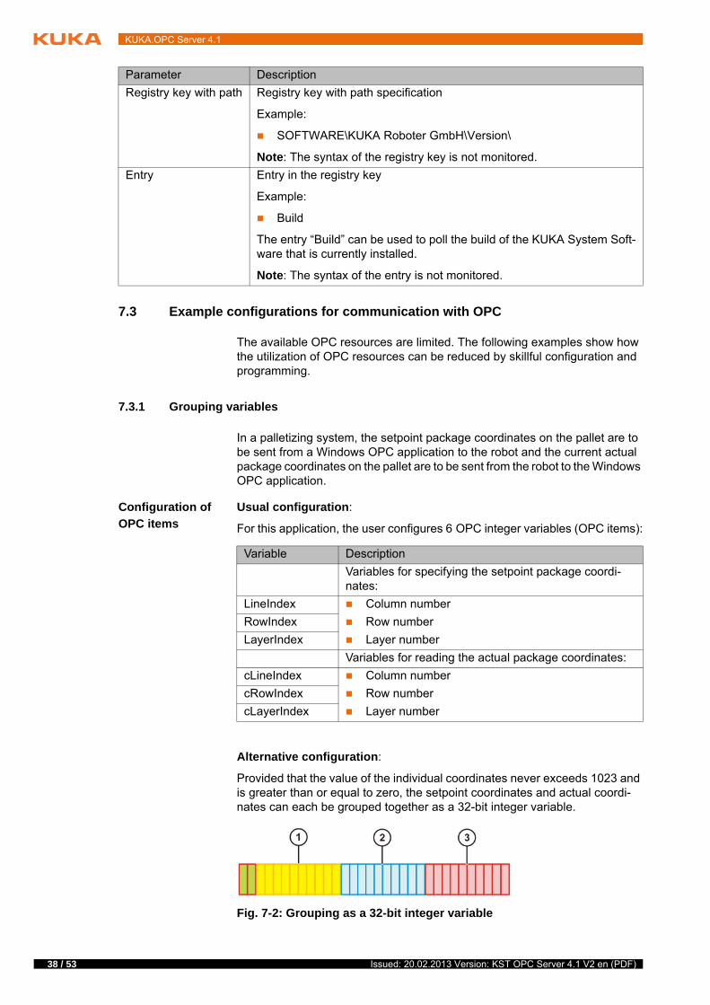
Alternative configuration:
Provided that the value of the individual coordinates never exceeds 1023 and is greater than or equal to zero, the setpoint coordinates and actual coordi-nates can each be grouped together as a 32-bit integer variable.
Registry key with path Registry key with path specification
Example:
SOFTWARE\KUKA Roboter GmbH\Version\
Note: The syntax of the registry key is not monitored.
Entry Entry in the registry key
Example:
Build
The entry “Build” can be used to poll the build of the KUKA System Soft-ware that is currently installed.
Note: The syntax of the entry is not monitored.
Parameter Description
Variable Description
Variables for specifying the setpoint package coordi-nates:
LineIndex Column number
Row number
Layer number
RowIndex
LayerIndex
Variables for reading the actual package coordinates:
cLineIndex Column number
Row number
Layer number
cRowIndex
cLayerIndex
Fig. 7-2: Grouping as a 32-bit integer variable
Issued: 20.02.2013 Version: KST OPC Server 4.1 V2 en (PDF)

7 Configuring the OPC server
By grouping the package coordinates, the user now only requires 2 OPC inte-ger variables (OPC items):
Programming the
OPC client
Example code in C# for the OPC client for grouping the 3 setpoint package co-ordinates as a specification for the robot:
Example code in C# for the OPC client for reading the 3 actual package coor-dinates:
Programming the
robot
Example code in KRL for the robot for ungrouping the 3 setpoint package co-ordinates:
Example code in KRL for the robot for grouping the 3 actual package coordi-nates:
1 10 bits for the layer 3 10 bits for the column
2 10 bits for the row
Variable Description
CommonIndex Variable for specifying the 3 setpoint package coordi-nates
cCommonIndex Variable for reading the 3 actual package coordinates
INT RowIndex, LineIndex, LayerIndex ;// Int32 but actually only 10 bits to useLineIndex = 3; // condition >=0 & <1024 RowIndex = 7; // condition >=0 & <1024LayerIndex = 15; // condition >=0 & <1024// Output as OPC variableINT CommonIndex = (LineIndex | RowIndex <<10 | LayerIndex<<20);
INT cCommonIndex = 0; // Input as OPC variable – current Coordinates...INT cLineIndex = (cCommonIndex & 1023); // extracts index line from cCommonIndexINT cRowIndex = (cCommonIndex >> 10 & 1023); // extracts index row from cCommonIndexINT cLayerIndex = (cCommonIndex >> 20 & 1023); // extracts index layer from cCommonIndex
DEFDAT $CONFIG...DECL INT CommonIndex = 0; this variable must be global available and mapped to OPCServer...
DEFDAT TEST...DECL INT LineIndex = 0; local copy of index lineDECL INT RowIndex = 0; local copy of index rowDECL INT LayerIndex = 0; local copy of index layer...DEF TEST()...LineIndex = (CommonIndex) B_AND 'B1111111111'; extracts index line from CommonIndexRowIndex = (CommonIndex / 'B10000000000') B_AND 'B1111111111'; extracts index row from CommonIndexLayerIndex = (CommonIndex / 'B100000000000000000000') B_AND 'B1111111111'; extracts index layer from CommonIndex
DEFDAT $CONFIG...DECL INT cCommonIndex = 0; this variable must be global available and mapped to OPCServer...
39 / 53Issued: 20.02.2013 Version: KST OPC Server 4.1 V2 en (PDF)

40 / 53
KUKA.OPC Server 4.1
7.3.2 Serial data transfer
The weight data of 20 packages are to be transferred from a Windows OPC application to a robotic palletizing system.
Programming the
robot
Usual programming:
For this application, the user declares one real variable per package weight in $CONFIG.DAT and defines these as readable and writable OPC items in the OPC configuration:
The variables configured in this way can be read and written directly as OPC items by the OPC client. The resource utilization rate is high, however, as 20 OPC real variables are required.
Alternative programming:
Provided that the information is not time-critical, the weight data can be trans-ferred serially. By grouping the weight data as an array, the user needs only a few OPC variables.
The user declares the following variables in $CONFIG.DAT:
For reading and writing the weight data sent by the OPC client to the robot, the user writes a KRL program that is called cyclically. For this, the program is in-
DEFDAT TEST...DECL INT cLineIndex = 0; current index lineDECL INT cRowIndex = 0; current index rowDECL INT cLayerIndex = 0; current index layer...DEF TEST()...cCommonIndex = cLayerIndex *'B100000000000000000000' + cRowIndex *'B10000000000' + cLineIndex
DEFDAT $CONFIG...DECL Real Package1Weight=0.0DECL Real Package2Weight=0.0
...DECL Real Package20Weight=0.0
Variable Description
Package-Weight[20]
Array with 20 real variables: PackageWeight[1] … PackageWeight[20]
PackageWeight_t Temporary real variable to which the package weight is written
PackageIndex Integer variable for the package index
DEFDAT $CONFIG...DECL Real PackageWeight[20]PackageWeight[1]=0.0PackageWeight[2]=0.0...PackageWeight[19]=0.0PackageWeight[20]=0.0
DECL Real PackageWeight_t =0.0
DECL Int PackageIndex=1
Issued: 20.02.2013 Version: KST OPC Server 4.1 V2 en (PDF)

7 Configuring the OPC server
tegrated into the Submit interpreter. This is usually the SUB program SPS.SUB.
When a package index between 1 and 20 is read from the PackageIndex vari-able, the program writes the package weight from the variable PackageWeight_t to the array PackageWeight[20] in $CONFIG.DAT, this is, to the variable with the corresponding package index. Finally, the PackageIn-dex variable is overwritten with zero to prevent further write operations.
Programming the
OPC client
Example code in C# for the OPC client for setting the package weight:
Configuration of
OPC items
The user configures the following OPC variables (OPC items):
Overview
Extended config-
uration
The weight data of the packages is to be determined in the robotic palletizing system and sent to the OPC client.
Example code in C# for the OPC client for reading the package weight:
DEF Read_Weight() IF (PackageIndex > 0) AND (PackageIndex < 21) THEN PackageWeight[PackageIndex] = PackageWeight_t
PackageIndex = 0 ENDIFEND
bool SetPackageWeight(int pi, double pw){ int _pi; if (PackageIndex.read(out _pi) == true) { if (_pi == 0) { if (PackageIndex.write(pw) == true) { //insert if necessary a delay if (PackageIndex.write(pi) == true) { return true; } } } } return false;}
Variable Variable type Access type Polling type
PackageWeight_t
Real ReadWrite Event
PackageIndex Integer ReadWrite Event
Fig. 7-3: Transferring weight data to the robot (example)
41 / 53Issued: 20.02.2013 Version: KST OPC Server 4.1 V2 en (PDF)

42 / 53
KUKA.OPC Server 4.1
The user additionally configures the following OPC variable (OPC item):
Extended
overview
bool GetPackageWeight(int pi, out double pw){ int _pi; if (PackageIndex.read(out _pi) == true) { if (_pi == 0) double[] pwArray; if (PackageIndex.read(out _pi) == true) { if (PackageWeight.read(out pwArray) == true) { if (pwArray != null) { if (pwArray.Count() >= pi) { pw = pwArray[pi - 1]; return true; } } } } } return false;}
Variable Variable type Access type Polling type
PackageWeight RealArray Read Event
Fig. 7-4: Transferring weight data to the robot (extended example)
Issued: 20.02.2013 Version: KST OPC Server 4.1 V2 en (PDF)

8 KUKA Service
8 KUKA Service
8.1 Requesting support
Introduction The KUKA Roboter GmbH documentation offers information on operation and provides assistance with troubleshooting. For further assistance, please con-tact your local KUKA subsidiary.
Information The following information is required for processing a support request:
Model and serial number of the robot
Model and serial number of the controller
Model and serial number of the linear unit (if applicable)
Model and serial number of the energy supply system (if applicable)
Version of the KUKA System Software
Optional software or modifications
Archive of the software
For KUKA System Software V8: instead of a conventional archive, gener-ate the special data package for fault analysis (via KrcDiag).
Application used
Any external axes used
Description of the problem, duration and frequency of the fault
8.2 KUKA Customer Support
Availability KUKA Customer Support is available in many countries. Please do not hesi-tate to contact us if you have any questions.
Argentina Ruben Costantini S.A. (Agency)
Luis Angel Huergo 13 20
Parque Industrial
2400 San Francisco (CBA)
Argentina
Tel. +54 3564 421033
Fax +54 3564 428877
Australia Headland Machinery Pty. Ltd.
Victoria (Head Office & Showroom)
95 Highbury Road
Burwood
Victoria 31 25
Australia
Tel. +61 3 9244-3500
Fax +61 3 9244-3501
www.headland.com.au
43 / 53Issued: 20.02.2013 Version: KST OPC Server 4.1 V2 en (PDF)

44 / 53
KUKA.OPC Server 4.1
Belgium KUKA Automatisering + Robots N.V.
Centrum Zuid 1031
3530 Houthalen
Belgium
Tel. +32 11 516160
Fax +32 11 526794
www.kuka.be
Brazil KUKA Roboter do Brasil Ltda.
Travessa Claudio Armando, nº 171
Bloco 5 - Galpões 51/52
Bairro Assunção
CEP 09861-7630 São Bernardo do Campo - SP
Brazil
Tel. +55 11 4942-8299
Fax +55 11 2201-7883
www.kuka-roboter.com.br
Chile Robotec S.A. (Agency)
Santiago de Chile
Chile
Tel. +56 2 331-5951
Fax +56 2 331-5952
www.robotec.cl
China KUKA Robotics China Co.,Ltd.
Songjiang Industrial Zone
No. 388 Minshen Road
201612 Shanghai
China
Tel. +86 21 6787-1888
Fax +86 21 6787-1803
www.kuka-robotics.cn
Germany KUKA Roboter GmbH
Zugspitzstr. 140
86165 Augsburg
Germany
Tel. +49 821 797-4000
Fax +49 821 797-1616
www.kuka-roboter.de
Issued: 20.02.2013 Version: KST OPC Server 4.1 V2 en (PDF)

8 KUKA Service
France KUKA Automatisme + Robotique SAS
Techvallée
6, Avenue du Parc
91140 Villebon S/Yvette
France
Tel. +33 1 6931660-0
Fax +33 1 6931660-1
www.kuka.fr
India KUKA Robotics India Pvt. Ltd.
Office Number-7, German Centre,
Level 12, Building No. - 9B
DLF Cyber City Phase III
122 002 Gurgaon
Haryana
India
Tel. +91 124 4635774
Fax +91 124 4635773
www.kuka.in
Italy KUKA Roboter Italia S.p.A.
Via Pavia 9/a - int.6
10098 Rivoli (TO)
Italy
Tel. +39 011 959-5013
Fax +39 011 959-5141
www.kuka.it
Japan KUKA Robotics Japan K.K.
YBP Technical Center
134 Godo-cho, Hodogaya-ku
Yokohama, Kanagawa
240 0005
Japan
Tel. +81 45 744 7691
Fax +81 45 744 7696
Canada KUKA Robotics Canada Ltd.
6710 Maritz Drive - Unit 4
Mississauga
L5W 0A1
Ontario
Canada
Tel. +1 905 670-8600
Fax +1 905 670-8604
www.kuka-robotics.com/canada
45 / 53Issued: 20.02.2013 Version: KST OPC Server 4.1 V2 en (PDF)

46 / 53
KUKA.OPC Server 4.1
Korea KUKA Robotics Korea Co. Ltd.
RIT Center 306, Gyeonggi Technopark
1271-11 Sa 3-dong, Sangnok-gu
Ansan City, Gyeonggi Do
426-901
Korea
Tel. +82 31 501-1451
Fax +82 31 501-1461
Malaysia KUKA Robot Automation Sdn Bhd
South East Asia Regional Office
No. 24, Jalan TPP 1/10
Taman Industri Puchong
47100 Puchong
Selangor
Malaysia
Tel. +60 3 8061-0613 or -0614
Fax +60 3 8061-7386
Mexico KUKA de México S. de R.L. de C.V.
Progreso #8
Col. Centro Industrial Puente de Vigas
Tlalnepantla de Baz
54020 Estado de México
Mexico
Tel. +52 55 5203-8407
Fax +52 55 5203-8148
www.kuka-robotics.com/mexico
Norway KUKA Sveiseanlegg + Roboter
Sentrumsvegen 5
2867 Hov
Norway
Tel. +47 61 18 91 30
Fax +47 61 18 62 00
Austria KUKA Roboter Austria GmbH
Vertriebsbüro Österreich
Regensburger Strasse 9/1
4020 Linz
Austria
Tel. +43 732 784752
Fax +43 732 793880
www.kuka-roboter.at
Issued: 20.02.2013 Version: KST OPC Server 4.1 V2 en (PDF)

8 KUKA Service
Poland KUKA Roboter Austria GmbH
Spółka z ograniczoną odpowiedzialnością
Oddział w Polsce
Ul. Porcelanowa 10
40-246 Katowice
Poland
Tel. +48 327 30 32 13 or -14
Fax +48 327 30 32 26
Portugal KUKA Sistemas de Automatización S.A.
Rua do Alto da Guerra n° 50
Armazém 04
2910 011 Setúbal
Portugal
Tel. +351 265 729780
Fax +351 265 729782
Russia OOO KUKA Robotics Rus
Webnaja ul. 8A
107143 Moskau
Russia
Tel. +7 495 781-31-20
Fax +7 495 781-31-19
kuka-robotics.ru
Sweden KUKA Svetsanläggningar + Robotar AB
A. Odhners gata 15
421 30 Västra Frölunda
Sweden
Tel. +46 31 7266-200
Fax +46 31 7266-201
Switzerland KUKA Roboter Schweiz AG
Industriestr. 9
5432 Neuenhof
Switzerland
Tel. +41 44 74490-90
Fax +41 44 74490-91
www.kuka-roboter.ch
47 / 53Issued: 20.02.2013 Version: KST OPC Server 4.1 V2 en (PDF)
48 / 53
KUKA.OPC Server 4.1
Spain KUKA Robots IBÉRICA, S.A.
Pol. Industrial
Torrent de la Pastera
Carrer del Bages s/n
08800 Vilanova i la Geltrú (Barcelona)
Spain
Tel. +34 93 8142-353
Fax +34 93 8142-950
www.kuka-e.com
South Africa Jendamark Automation LTD (Agency)
76a York Road
North End
6000 Port Elizabeth
South Africa
Tel. +27 41 391 4700
Fax +27 41 373 3869
www.jendamark.co.za
Taiwan KUKA Robot Automation Taiwan Co., Ltd.
No. 249 Pujong Road
Jungli City, Taoyuan County 320
Taiwan, R. O. C.
Tel. +886 3 4331988
Fax +886 3 4331948
www.kuka.com.tw
Thailand KUKA Robot Automation (M)SdnBhd
Thailand Office
c/o Maccall System Co. Ltd.
49/9-10 Soi Kingkaew 30 Kingkaew Road
Tt. Rachatheva, A. Bangpli
Samutprakarn
10540 Thailand
Tel. +66 2 7502737
Fax +66 2 6612355
www.kuka-roboter.de
Czech Republic KUKA Roboter Austria GmbH
Organisation Tschechien und Slowakei
Sezemická 2757/2
193 00 Praha
Horní Počernice
Czech Republic
Tel. +420 22 62 12 27 2
Fax +420 22 62 12 27 0
Issued: 20.02.2013 Version: KST OPC Server 4.1 V2 en (PDF)

8 KUKA Service
Hungary KUKA Robotics Hungaria Kft.
Fö út 140
2335 Taksony
Hungary
Tel. +36 24 501609
Fax +36 24 477031
USA KUKA Robotics Corporation
51870 Shelby Parkway
Shelby Township
48315-1787
Michigan
USA
Tel. +1 866 873-5852
Fax +1 866 329-5852
www.kukarobotics.com
UK KUKA Automation + Robotics
Hereward Rise
Halesowen
B62 8AN
UK
Tel. +44 121 585-0800
Fax +44 121 585-0900
49 / 53Issued: 20.02.2013 Version: KST OPC Server 4.1 V2 en (PDF)

50 / 53
KUKA.OPC Server 4.1
Issued: 20.02.2013 Version: KST OPC Server 4.1 V2 en (PDF)

Index
Index
Symbols$SPOC_MOTION_ENABLE 11, 13, 33$USER_SAF 11, 13, 33
AAccess functions 11Access permissions, assigning 24ACL 6Activation permissions, assigning 25Areas of application, OPC server 10
CCOM Security, tab 24Communication 9Configuration tips 12Configuration, OPC client 21Configuration, OPC server 33CRR 6
DData, serial transfer 40DCOM 6DCOM settings, configuration 21DCOM, enabling 23Default Properties, tab 23Default Protocols, tab 27Documentation, industrial robot 5
EEvent 7, 12, 35Event-dependent reading 35Example clients 11
FFunctions, OPC server 9
IInstallation 15Installation, OPC Server 15Introduction 5IP 7Item ID 7
KKLI 6KLI, configuration 31Knowledge, required 5KR C 6KUKA Cross 6KUKA Customer Support 43
LLaunch permissions, assigning 25
OOLE 6OPC 6OPC client 6, 10
OPC DA 6OPC DA client 10OPC DA client, configuration 21OPC DA client, connecting 17OPC item 6OPC items, changing 34OPC items, creating 34OPC items, deleting 35OPC server, configuration 33OPC server, manual start 17OPC XML DA client 10OPC XML DA client, configuration 21OPC XML DA client, connecting 18OPC XML-DA 6OpcEnum 7, 29, 30Operation 17Overview, OPC Server 9Overview, user interface 33
PPLC 7Polling 7, 12, 35Port range, DCOM communication 27Product description 9
SSafety 13Safety instructions 5Service, KUKA Roboter 43SetInfo 11SetVar 11ShowVar 11Single point of control 13smartHMI 6smartPAD 6SPOC 7, 13Subnet 7Support request 43Synchronous reading 7, 35System requirements 15System requirements, hardware 15System requirements, software 15
TTarget group 5TCP/IP 7Terms used 6Trademarks 7Training 5
UUninstallation, OPC Server 15Updating, OPC Server 15URL 7User administration 11User groups 22User interface, OPC configuration 33Users 22
51 / 53Issued: 20.02.2013 Version: KST OPC Server 4.1 V2 en (PDF)

52 / 53
KUKA.OPC Server 4.1
VVariables, grouping 38Variables, reading and writing 11VxWorks 7
WWarnings 5
Issued: 20.02.2013 Version: KST OPC Server 4.1 V2 en (PDF)

53 / 53Issued: 20.02.2013 Version: KST OPC Server 4.1 V2 en (PDF)
KUKA.OPC Server 4.1