Embed Size (px)
Citation preview
Keithley Instruments 28775 Aurora Road Cleveland, Ohio 44139 1-800-833-9200tek.com/keithley
KTTI-TSP Communication and Digital I/O Accessory Instruction Sheet
077143801 Februrary 2021 *P077143801* 1
Introduction The KTTI-TSP Communication and Digital I/O Accessory card provides instruments that have an accessory card slot with a TSP-Link® interface that allows the instrument to trigger and communicate with other TSP-Link equipped instruments.
Keithley Instruments TSP-Link is a high-speed trigger synchronization and communication bus that test-system builders can use to connect multiple instruments in a master and subordinate configuration. Using TSP-Link, multiple instruments can be connected and used as if they are part of the same physical unit for simultaneous multi-channel testing. The test system can be expanded to include up to 32 TSP-Link-enabled instruments.
Once connected, all the instruments that are equipped with TSP-Link can be programmed and operated under the control of the master instrument or instruments. This allows instruments to run tests more quickly because they can be decoupled from frequent computer interaction. The test system can have multiple master and subordinate groups that can handle multi-device testing in parallel. Combining TSP-Link with a flexible programmable trigger model ensures speed.
The card provides six independently configurable digital input/output lines that can be used to control external digital circuitry, for example, a handler that is used to perform binning operations. The digital I/O port is a standard female DB-9 connector. You can also use these lines for triggering. The instrument can generate output trigger pulses and detect input trigger pulses.
This card requires a shielded twisted-pair Category 5e LAN crossover cable that allows triggering and communications between ethernet-enabled instruments and TSP-Link enabled instruments.
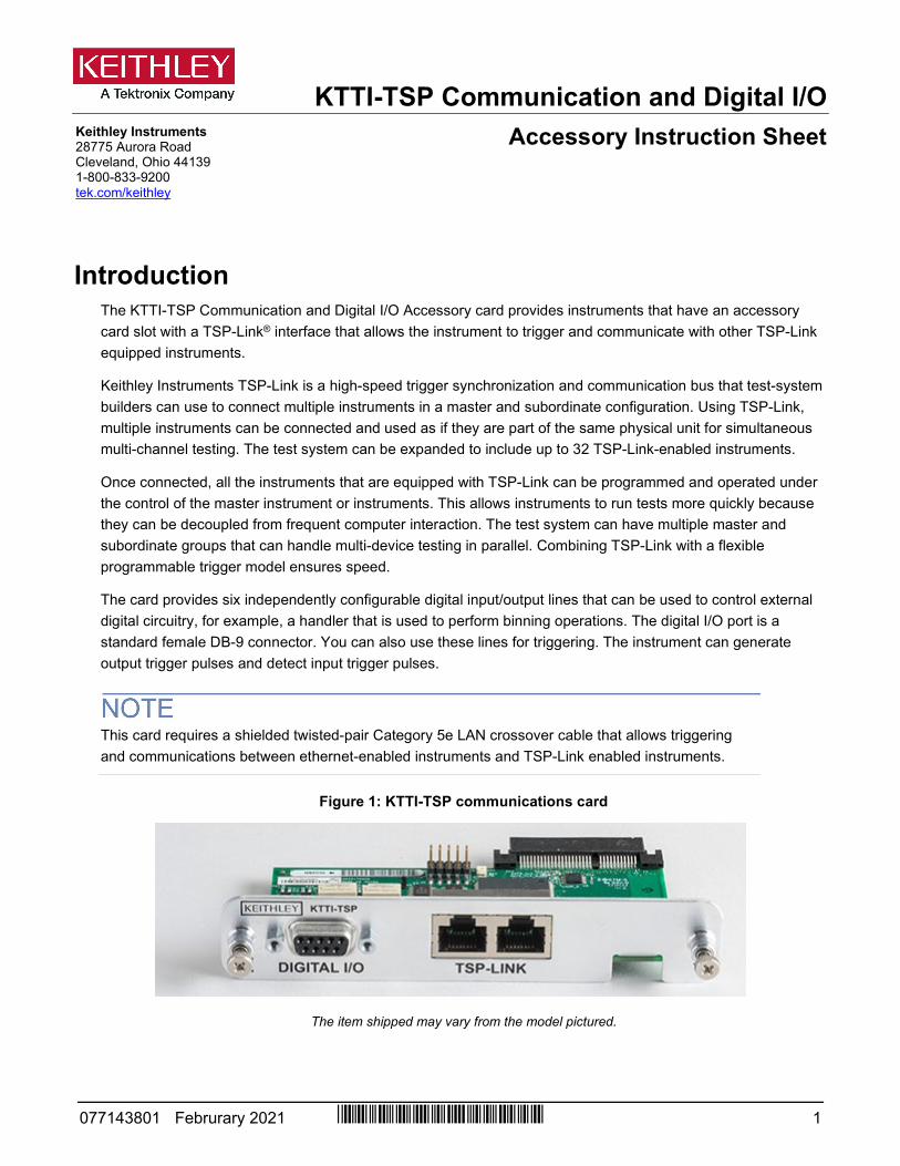
Figure 1: KTTI-TSP communications card
The item shipped may vary from the model pictured.
KTTI-TSP Communication and Digital I/O Accessory Instruction Sheet
2 077143801 / Februrary 2021
General specifications General ratings for the KTTI-TSP are listed in the following table.
Category Specification TSP-Link Interface Maximum connections: Connect up to 32 instruments
I/O connector: RJ-45 Cable: Shielded twisted-pair Category 5e LAN crossover cable
Environmental conditions I/O connector: CAT5/RJ-45 Operating temperature: 0 °C to 55 °C Storage temperature: –20 °C to 80 °C Relative humidity: 5% to 95%, noncondensing Power consumption: +5.0 V: 250 mA (typical), 300 mA (maximum) Dimensions, (not including connectors): 120 mm (4.72 in.) x 64.5 mm (2.54 in.)
Digital I/O Connector: 9-pin female D 5V Power supply Pin: Limited to 500 mA at > 4 V (solid-state fuse protected) Lines: Six input/output, user-defined, for digital I/O or triggering Input signal levels: 0.7 V (maximum logic low), 3.7 V (minimum logic high) Input voltage limits: –0.25 V (absolute minimum), +5.25 V (absolute maximum) Maximum source current: +2.0 mA at >2.7 V (per pin) Maximum sink current: –50 mA at 0.7 V (per pin, solid-state fuse protected)
Environmental conditions Operating environment: Temperature 18 ºC to 28 ºC, 5% to 80% relative humidity, noncondensing Storage environment: –25 ºC to 65 ºC
Unpack and inspect Make sure to handle the KTTI-TSP carefully. Always grasp the card by the side edges. Do not touch board surfaces, components, or areas adjacent to electrical contacts. Contamination from foreign materials such as dirt, dust, and body oils can substantially degrade card performance.
To unpack and inspect your card:
1. Inspect the box for damage.
2. Open the box.
3. Remove the card and inspect for any obvious signs of physical damage.
4. Report any damage to the shipping agent immediately.
Installation
Slot covers must be installed on unused slots to prevent personal contact with high-voltage circuits. Failure to recognize and observe standard safety precautions could result in personal injury or death due to electric shock.
KTTI-TSP Communication and Digital I/O Accessory Instruction Sheet
077143801 / Februrary 2021 3
To install the communications card:
1. Turn the instrument off and disconnect the power line cord and any other cables connected to the rear panel.
2. Position the instrument so that you are facing the rear panel.
3. Remove the slot cover plate from the slot on the back of the instrument. Retain the plate and screws for future use.
4. Align the card with the connector toward the inside edge of the slot and slide the card into the chassis. For the last ¼ inch, press in firmly to mate the card to the connector.
5. On each side of the card, there is a spring-loaded mounting screw. Tighten these two screws, either by hand or with a Phillips-head screwdriver, to secure the card in the case. Do not overtighten.
6. Reconnect the power line cable and any other cables to the rear panel.
7. Turn on the instrument.
Making TSP-Link connections The TSP-Link expansion interface uses CAT5 and RJ-45 connectors to connect up to 32 devices.
TSP-Link Operation The instrument recognizes the installed communications card when the power is turned on. Once connected, all instruments that are equipped with TSP-Link in a test system can be programmed and operated under the control of the master instrument or instruments.
This allows instruments to:
Run tests more quickly because they can be decoupled from frequent computer interaction. Have multiple master and subordinate groups. Handle multi-device testing in parallel. When combined with a flexible programmable trigger model, ensure speed. Use multiple instruments as if they are part of the same physical instrument for simultaneous multi-channel
testing.
You can run a script from the front panel of any connected instrument (node). When a script is run, all the other instruments go into remote operation and the instrument running the script becomes the primary and the other instruments become subordinates. When the script is finished running, all the nodes return to local operation and the primary/subordinate relationship between nodes is dissolved.
Each instrument attached to the TSP-Link network must be identified by a unique TSP-Link node number.
Refer to the instrument reference manual for information about controlling the instrument from a remote interface.
KTTI-TSP Communication and Digital I/O Accessory Instruction Sheet
4 077143801 / Februrary 2021
TSP-Link Configuration To configure the TSP-Link card from the front panel:
1. Press the MENU key.
2. Under the System column, select Communication. The SYSTEM COMMUNICATIONS window opens.
3. Select the TSP-Link tab.
4. Select the Node option. The TSP-Link Node screen appears.
5. Set the node number and select OK.
6. Select Initialize and the instrument forms a network with other connected TSP-Link instruments.
Digital I/O The KTTI-TSP digital I/O port provides six independently configurable digital input/output lines.
You can use these lines for digital control by writing a bit pattern to the digital I/O lines. Digital control is used for applications such as providing binning codes to a component handler. Digital control uses the state of the line to determine the action to take.
You can also use these lines for triggering by using the transition of the line state to initiate an action. The instrument can generate output trigger pulses and detect input trigger pulses. Triggering is used for applications such as synchronizing the operations of a measurement instrument with the operations of other instruments.
You cannot configure or directly control the digital I/O lines from the front panel. To configure and control any of the six digital input/output lines, you need to send commands to the KTTI-TSP over a remote interface. You can use either the SCPI or TSP command set.
See "Remote digital I/O commands (on page 14)" for information about setting up a remote interface and choosing a command set.
KTTI-TSP Communication and Digital I/O Accessory Instruction Sheet
077143801 / Februrary 2021 5
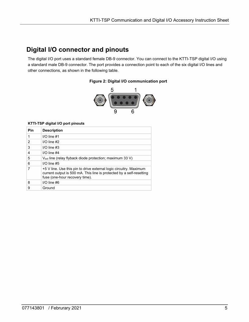
Digital I/O connector and pinouts The digital I/O port uses a standard female DB-9 connector. You can connect to the KTTI-TSP digital I/O using a standard male DB-9 connector. The port provides a connection point to each of the six digital I/O lines and other connections, as shown in the following table.
Figure 2: Digital I/O communication port
KTTI-TSP digital I/O port pinouts
Pin Description 1 I/O line #1 2 I/O line #2 3 I/O line #3 4 I/O line #4 5 Vext line (relay flyback diode protection; maximum 33 V) 6 I/O line #5 7 +5 V line. Use this pin to drive external logic circuitry. Maximum
current output is 500 mA. This line is protected by a self-resetting fuse (one-hour recovery time).
8 I/O line #6 9 Ground
KTTI-TSP Communication and Digital I/O Accessory Instruction Sheet
6 077143801 / Februrary 2021
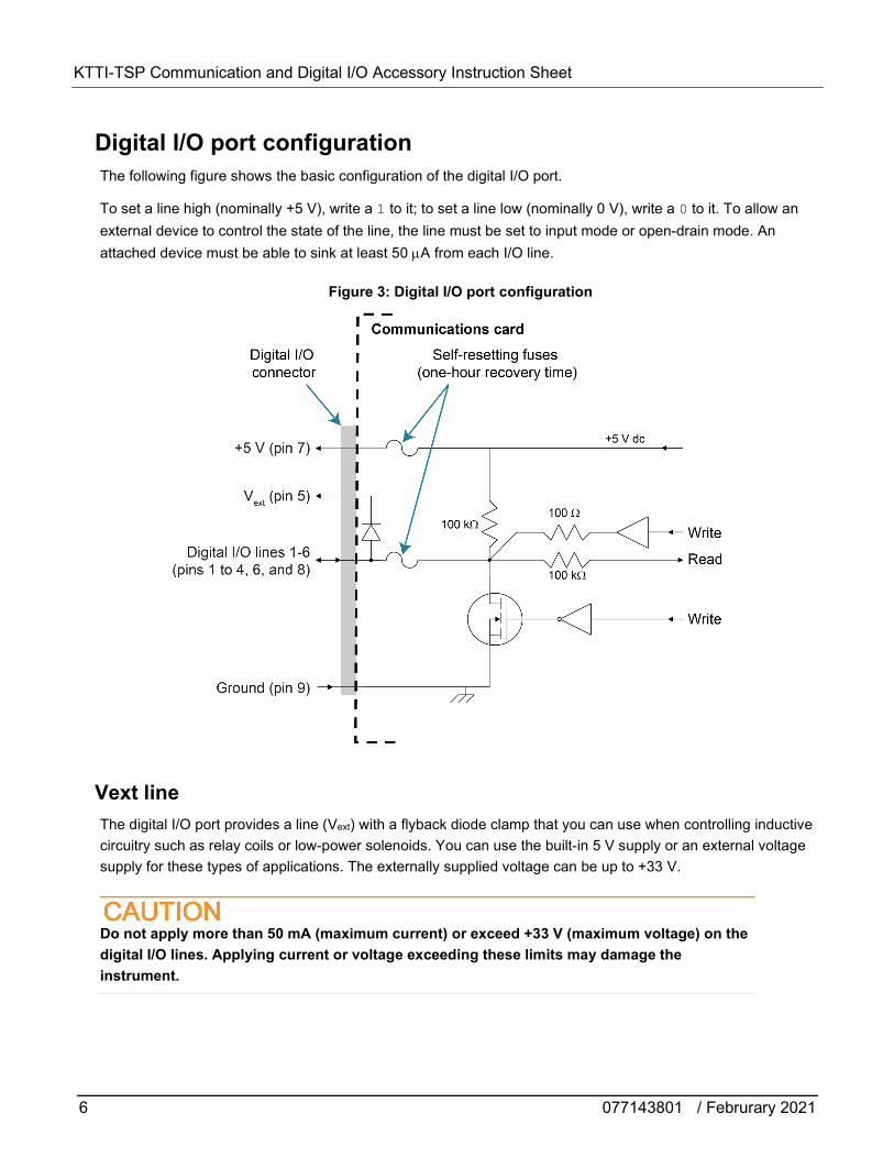
Digital I/O port configuration The following figure shows the basic configuration of the digital I/O port.
To set a line high (nominally +5 V), write a 1 to it; to set a line low (nominally 0 V), write a 0 to it. To allow an external device to control the state of the line, the line must be set to input mode or open-drain mode. An attached device must be able to sink at least 50 µA from each I/O line.
Figure 3: Digital I/O port configuration
Vext line The digital I/O port provides a line (Vext) with a flyback diode clamp that you can use when controlling inductive circuitry such as relay coils or low-power solenoids. You can use the built-in 5 V supply or an external voltage supply for these types of applications. The externally supplied voltage can be up to +33 V.
Do not apply more than 50 mA (maximum current) or exceed +33 V (maximum voltage) on the digital I/O lines. Applying current or voltage exceeding these limits may damage the instrument.
KTTI-TSP Communication and Digital I/O Accessory Instruction Sheet
077143801 / Februrary 2021 7
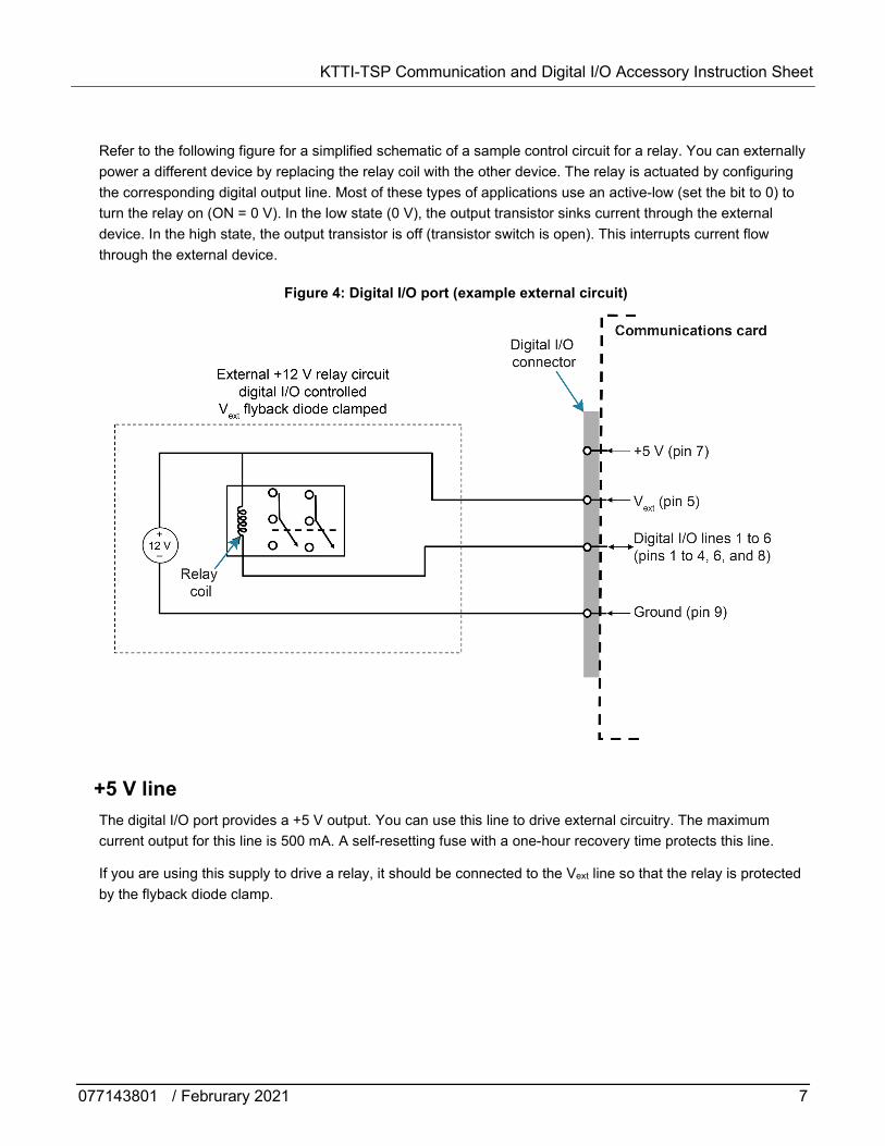
Refer to the following figure for a simplified schematic of a sample control circuit for a relay. You can externally power a different device by replacing the relay coil with the other device. The relay is actuated by configuring the corresponding digital output line. Most of these types of applications use an active-low (set the bit to 0) to turn the relay on (ON = 0 V). In the low state (0 V), the output transistor sinks current through the external device. In the high state, the output transistor is off (transistor switch is open). This interrupts current flow through the external device.
Figure 4: Digital I/O port (example external circuit)
+5 V line The digital I/O port provides a +5 V output. You can use this line to drive external circuitry. The maximum current output for this line is 500 mA. A self-resetting fuse with a one-hour recovery time protects this line.
If you are using this supply to drive a relay, it should be connected to the Vext line so that the relay is protected by the flyback diode clamp.
KTTI-TSP Communication and Digital I/O Accessory Instruction Sheet
8 077143801 / Februrary 2021
Digital I/O lines You can place each digital I/O line into one of the following modes:
Digital open-drain, output, or input Trigger open-drain, output, or input Trigger synchronous master or acceptor
When you configure the digital I/O lines for triggering applications, configure the output lines before the input lines. This prevents possible false input trigger detection in certain situations.
Digital control modes If you are setting a line for digital control, you can set the line to be open-drain, output, or input, as described in the following topics.
Open-drain When you place a line in open-drain mode, the line is configured to be an open-drain signal with a 100 kΩ pull-up resistor. This makes the line compatible with other instruments that use open-drain digital I/O lines, such as other Keithley Instruments products that only support open-drain for its digital I/O. In this mode, the line can serve as an input, an output, or both. You can read from the line or write to it. When a digital I/O line is used as an input in open-drain mode, you must write a 1 to the line to enable it to detect logic levels that are generated from external sources.
Output When you place a line in output mode, you can set the line as logic high (+5 V) or as logic low (0 V). The default level is logic low (0 V). When the instrument is in output mode, the line is actively driven high or low. Unlike the input or open-drain modes, it will not respond to externally generated logic levels.
When you read the line, it shows the present output status and an event message is generated.
Input The input mode is similar to the open-drain mode, except that a line in this mode is intended to be used strictly as an input. When you place a line in input mode, the instrument automatically writes a 1 to the line to enable it to detect externally generated logic levels.
You can read an input line, but you cannot write to it. You also cannot change the logic level while the line is in input mode. If you attempt to change the logic level of a line that is in input mode, an event message is generated.
KTTI-TSP Communication and Digital I/O Accessory Instruction Sheet
077143801 / Februrary 2021 9
Trigger control modes You can use the trigger control modes to synchronize instrument operation with the operation of other instruments. These modes either detect or generate transitions in the state of the line, from high to low (falling edge) or from low to high (rising edge). The input edge detection setting of the instrument determines which type of transition is detected as an input trigger. Output triggers are typically generated in the form of a pulse. The type of transition that occurs on the leading edge of the pulse is determined by an output logic setting. The duration of the pulse is determined by a pulse width setting.
You can use the trigger control modes with interactive triggering or with the trigger model. For more information about the trigger modes and triggering, refer to the triggering section of the instrument reference manual.
Open-drain When you set the instrument to trigger mode and place a line in open-drain mode, the line is configured to be an open-drain signal with a 100 kΩ pull-up resistor. This makes the line compatible with other instruments that use open-drain trigger signals, such as other Keithley Instruments products that only support open-drain for its digital I/O. In this mode, you can use the line to detect input triggers or generate output triggers, or both. To use this mode successfully, you must carefully configure the input edge and output logic settings because both of these affect the initial state of the trigger line. It is recommended that you reset the line before selecting and configuring this mode.
To use the line only as a trigger input:
1. Reset the line.
2. Set the input trigger edge detection type to falling, rising, or either.
The command that sets the detection type automatically sets the line high. This enables the line to respond to and detect externally generated triggers.
Do not set the output trigger logic type to positive after setting the edge detection type. This sets the line low, which will prevent the line from operating correctly as a trigger input.
KTTI-TSP Communication and Digital I/O Accessory Instruction Sheet
10 077143801 / Februrary 2021
To use the line only as a trigger output:
1. Reset the line.
2. Set the output trigger logic type to negative (falling edge) or positive (rising edge).
When you set the logic type to negative, the instrument automatically sets the line high. Setting the logic type to positive automatically sets the line low.
Do not set the input trigger edge detection type after setting the positive logic type. This will set the line high, which will prevent the line from operating correctly as a trigger output.
To use the line as both a trigger input and a trigger output (falling edge triggers only):
1. Reset the line.
2. Set the output trigger logic type to negative (falling edge).
3. Set the input trigger edge detection type to falling, rising, or either.
You can use these settings for triggering applications that use Keithley Instrument products offering Trigger Link.
Output When you place a line in output mode, it is automatically set high or low depending on the output logic setting. Use the negative logic setting when you want to generate a falling edge trigger. Use the positive logic setting when you want to generate a rising edge trigger. You cannot detect incoming triggers on a line configured as a trigger output.
Input When you place a line in input mode, it is automatically set high to allow it to respond to and detect externally generated triggers. Depending on the input edge detection setting, the line can detect falling-edge triggers, rising-edge triggers, or both.
The line cannot generate an output trigger if it is set to the trigger input mode.
KTTI-TSP Communication and Digital I/O Accessory Instruction Sheet
077143801 / Februrary 2021 11
Synchronous triggering The synchronous triggering modes allow you to:
Implement bidirectional triggering on a single trigger line Start operations on one or more external instruments using a single trigger line Wait for all instruments to complete all triggered actions
To coordinate non-Keithley instrumentation with synchronous triggering, the non-Keithley instrument must have a trigger mode that is similar to the synchronous acceptor or synchronous master trigger mode.
To use synchronous triggering, configure the triggering master to synchronous master trigger mode or the non-Keithley equivalent. Configure all other instruments in the test system to the synchronous acceptor trigger mode or equivalent.
Synchronous master
Use the synchronous master trigger mode with the synchronous acceptor mode or its non-Keithley equivalent.
Configure only one instrument as a synchronous master. Configure all other instruments that are connected to the synchronization line as synchronous acceptors.
When a digital I/O line is set to the synchronous master mode, it generates falling edge output triggers and detects rising edge input triggers on the same trigger line.
Instruments that are configured as synchronous acceptors detect the falling-edge trigger and begin their triggered actions. At the same time, they latch the line low and hold it in that state until their triggered actions complete. Each instrument configured as an acceptor releases the line upon completion of its triggered actions.
When all instruments have released the line, the line changes state and generates a rising edge trigger. This trigger is detected by the synchronous master, which then performs its next triggered action.
KTTI-TSP Communication and Digital I/O Accessory Instruction Sheet
12 077143801 / Februrary 2021
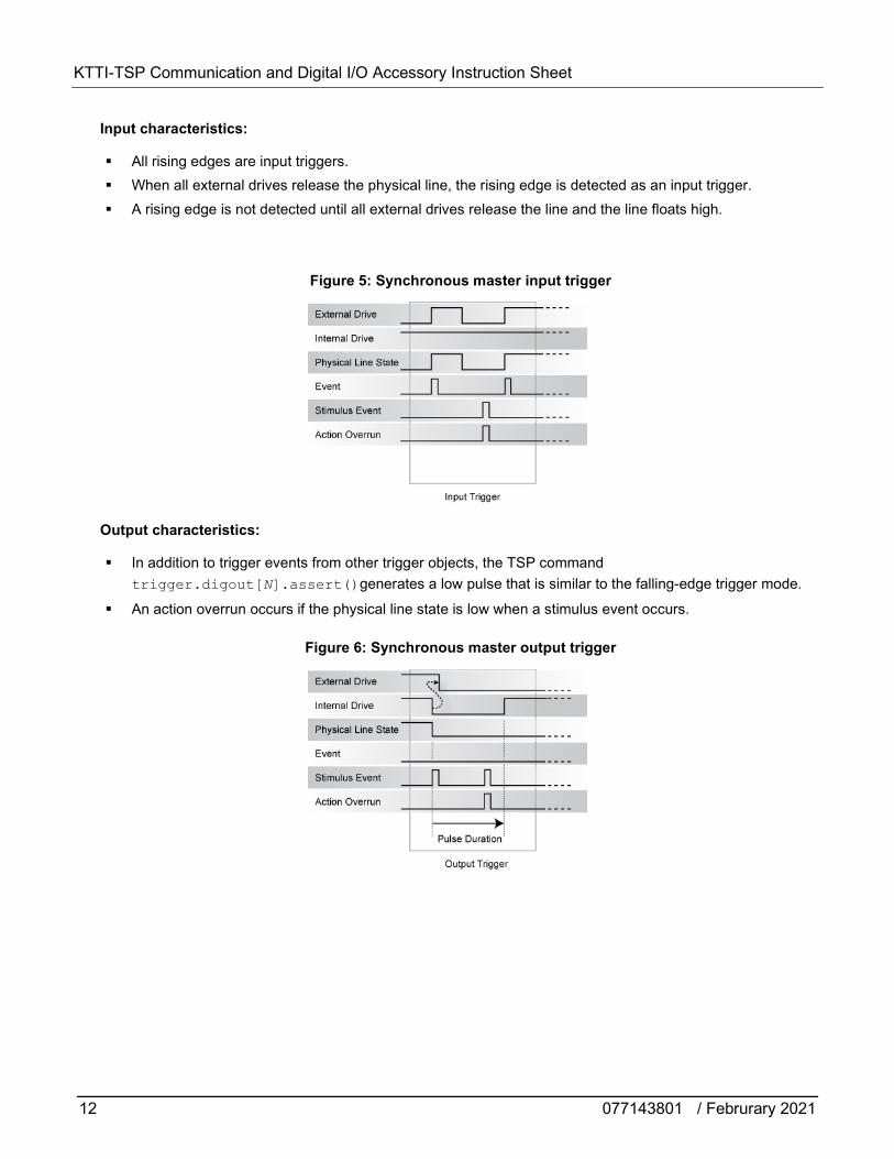
Input characteristics:
All rising edges are input triggers. When all external drives release the physical line, the rising edge is detected as an input trigger. A rising edge is not detected until all external drives release the line and the line floats high.
Figure 5: Synchronous master input trigger
Output characteristics:
In addition to trigger events from other trigger objects, the TSP command trigger.digout[N].assert()generates a low pulse that is similar to the falling-edge trigger mode.
An action overrun occurs if the physical line state is low when a stimulus event occurs.
Figure 6: Synchronous master output trigger
KTTI-TSP Communication and Digital I/O Accessory Instruction Sheet
077143801 / Februrary 2021 13
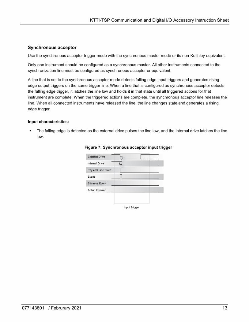
Synchronous acceptor Use the synchronous acceptor trigger mode with the synchronous master mode or its non-Keithley equivalent.
Only one instrument should be configured as a synchronous master. All other instruments connected to the synchronization line must be configured as synchronous acceptor or equivalent.
A line that is set to the synchronous acceptor mode detects falling edge input triggers and generates rising edge output triggers on the same trigger line. When a line that is configured as synchronous acceptor detects the falling edge trigger, it latches the line low and holds it in that state until all triggered actions for that instrument are complete. When the triggered actions are complete, the synchronous acceptor line releases the line. When all connected instruments have released the line, the line changes state and generates a rising edge trigger.
Input characteristics:
The falling edge is detected as the external drive pulses the line low, and the internal drive latches the line low.
Figure 7: Synchronous acceptor input trigger
KTTI-TSP Communication and Digital I/O Accessory Instruction Sheet
14 077143801 / Februrary 2021
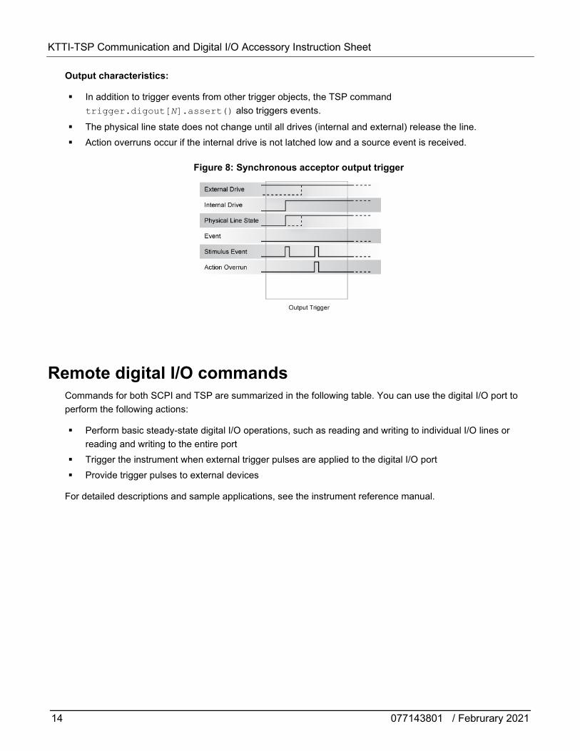
Output characteristics:
In addition to trigger events from other trigger objects, the TSP command trigger.digout[N].assert() also triggers events.
The physical line state does not change until all drives (internal and external) release the line. Action overruns occur if the internal drive is not latched low and a source event is received.
Figure 8: Synchronous acceptor output trigger
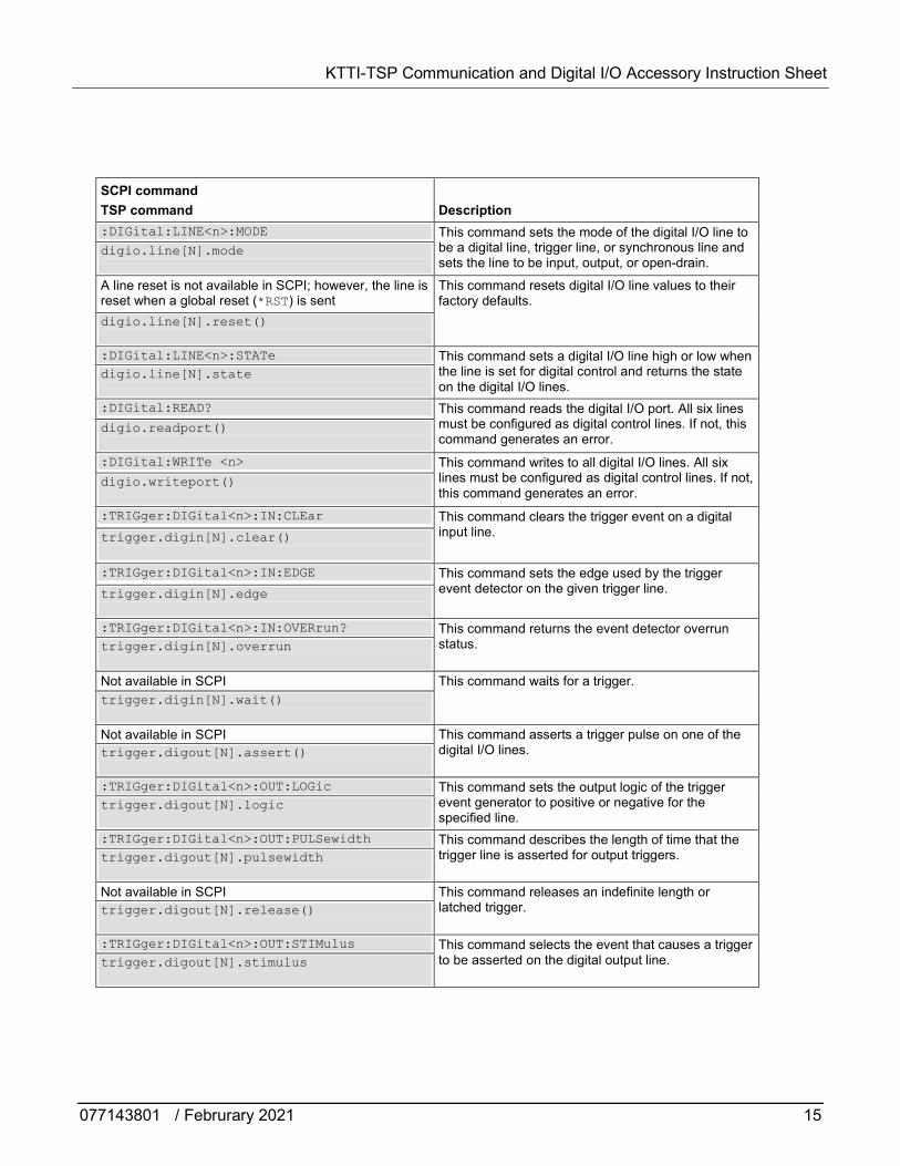
Remote digital I/O commands Commands for both SCPI and TSP are summarized in the following table. You can use the digital I/O port to perform the following actions:
Perform basic steady-state digital I/O operations, such as reading and writing to individual I/O lines or reading and writing to the entire port
Trigger the instrument when external trigger pulses are applied to the digital I/O port Provide trigger pulses to external devices
For detailed descriptions and sample applications, see the instrument reference manual.
KTTI-TSP Communication and Digital I/O Accessory Instruction Sheet
077143801 / Februrary 2021 15
SCPI command TSP command
Description
:DIGital:LINE<n>:MODE This command sets the mode of the digital I/O line to be a digital line, trigger line, or synchronous line and sets the line to be input, output, or open-drain.
digio.line[N].mode
A line reset is not available in SCPI; however, the line is reset when a global reset (*RST) is sent
This command resets digital I/O line values to their factory defaults.
digio.line[N].reset()
:DIGital:LINE<n>:STATe This command sets a digital I/O line high or low when the line is set for digital control and returns the state on the digital I/O lines.
digio.line[N].state
:DIGital:READ? This command reads the digital I/O port. All six lines must be configured as digital control lines. If not, this command generates an error.
digio.readport()
:DIGital:WRITe <n> This command writes to all digital I/O lines. All six lines must be configured as digital control lines. If not, this command generates an error.
digio.writeport()
:TRIGger:DIGital<n>:IN:CLEar This command clears the trigger event on a digital input line. trigger.digin[N].clear()
:TRIGger:DIGital<n>:IN:EDGE This command sets the edge used by the trigger event detector on the given trigger line. trigger.digin[N].edge
:TRIGger:DIGital<n>:IN:OVERrun? This command returns the event detector overrun
status. trigger.digin[N].overrun
Not available in SCPI This command waits for a trigger. trigger.digin[N].wait()
Not available in SCPI This command asserts a trigger pulse on one of the digital I/O lines. trigger.digout[N].assert()
:TRIGger:DIGital<n>:OUT:LOGic This command sets the output logic of the trigger
event generator to positive or negative for the specified line.
trigger.digout[N].logic
:TRIGger:DIGital<n>:OUT:PULSewidth This command describes the length of time that the trigger line is asserted for output triggers. trigger.digout[N].pulsewidth
Not available in SCPI This command releases an indefinite length or latched trigger. trigger.digout[N].release()
:TRIGger:DIGital<n>:OUT:STIMulus This command selects the event that causes a trigger
to be asserted on the digital output line.
trigger.digout[N].stimulus
KTTI-TSP Communication and Digital I/O Accessory Instruction Sheet
16 077143801 / Februrary 2021
To use the trigger model as a stimulus to a digital I/O line, you can use the trigger model Notify block. For information on the Notify block, see the reference manual for your instrument.
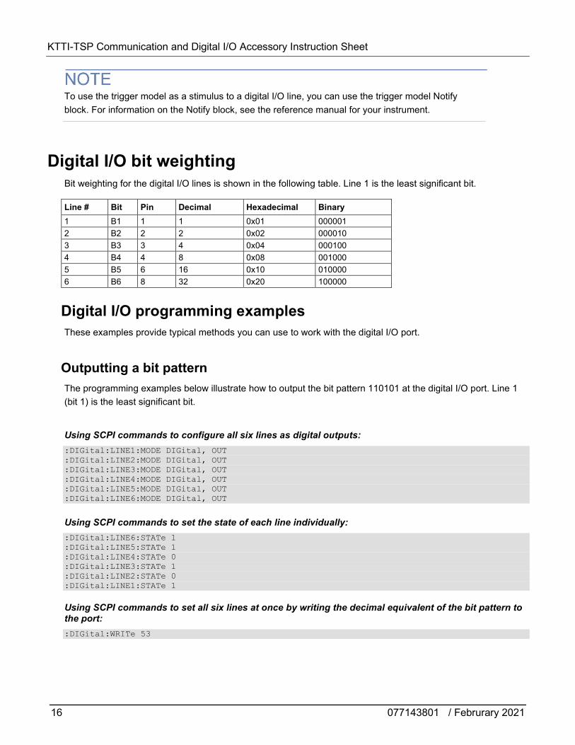
Digital I/O bit weighting Bit weighting for the digital I/O lines is shown in the following table. Line 1 is the least significant bit.
Line # Bit Pin Decimal Hexadecimal Binary 1 B1 1 1 0x01 000001 2 B2 2 2 0x02 000010 3 B3 3 4 0x04 000100 4 B4 4 8 0x08 001000 5 B5 6 16 0x10 010000 6 B6 8 32 0x20 100000
Digital I/O programming examples These examples provide typical methods you can use to work with the digital I/O port.
Outputting a bit pattern The programming examples below illustrate how to output the bit pattern 110101 at the digital I/O port. Line 1 (bit 1) is the least significant bit.
Using SCPI commands to configure all six lines as digital outputs: :DIGital:LINE1:MODE DIGital, OUT :DIGital:LINE2:MODE DIGital, OUT :DIGital:LINE3:MODE DIGital, OUT :DIGital:LINE4:MODE DIGital, OUT :DIGital:LINE5:MODE DIGital, OUT :DIGital:LINE6:MODE DIGital, OUT
Using SCPI commands to set the state of each line individually: :DIGital:LINE6:STATe 1 :DIGital:LINE5:STATe 1 :DIGital:LINE4:STATe 0 :DIGital:LINE3:STATe 1 :DIGital:LINE2:STATe 0 :DIGital:LINE1:STATe 1
Using SCPI commands to set all six lines at once by writing the decimal equivalent of the bit pattern to the port: :DIGital:WRITe 53
KTTI-TSP Communication and Digital I/O Accessory Instruction Sheet
077143801 / Februrary 2021 17
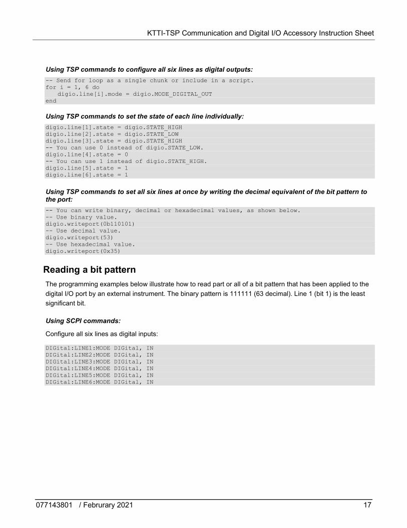
Using TSP commands to configure all six lines as digital outputs: -- Send for loop as a single chunk or include in a script. for i = 1, 6 do digio.line[i].mode = digio.MODE_DIGITAL_OUT end
Using TSP commands to set the state of each line individually: digio.line[1].state = digio.STATE_HIGH digio.line[2].state = digio.STATE_LOW digio.line[3].state = digio.STATE_HIGH -- You can use 0 instead of digio.STATE_LOW. digio.line[4].state = 0 -- You can use 1 instead of digio.STATE_HIGH. digio.line[5].state = 1 digio.line[6].state = 1
Using TSP commands to set all six lines at once by writing the decimal equivalent of the bit pattern to the port: -- You can write binary, decimal or hexadecimal values, as shown below. -- Use binary value. digio.writeport(0b110101) -- Use decimal value. digio.writeport(53) -- Use hexadecimal value. digio.writeport(0x35)
Reading a bit pattern The programming examples below illustrate how to read part or all of a bit pattern that has been applied to the digital I/O port by an external instrument. The binary pattern is 111111 (63 decimal). Line 1 (bit 1) is the least significant bit.
Using SCPI commands:
Configure all six lines as digital inputs:
DIGital:LINE1:MODE DIGital, IN DIGital:LINE2:MODE DIGital, IN DIGital:LINE3:MODE DIGital, IN DIGital:LINE4:MODE DIGital, IN DIGital:LINE5:MODE DIGital, IN DIGital:LINE6:MODE DIGital, IN
KTTI-TSP Communication and Digital I/O Accessory Instruction Sheet
18 077143801 / Februrary 2021
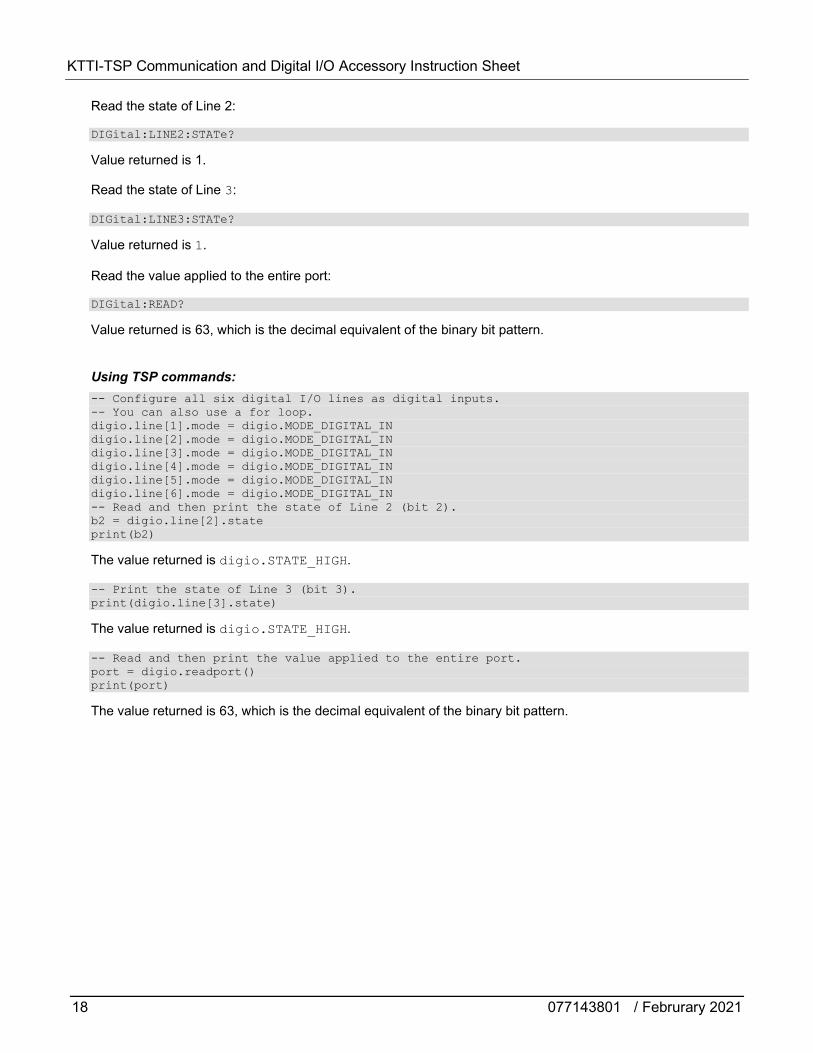
Read the state of Line 2:
DIGital:LINE2:STATe?
Value returned is 1.
Read the state of Line 3:
DIGital:LINE3:STATe?
Value returned is 1.
Read the value applied to the entire port:
DIGital:READ?
Value returned is 63, which is the decimal equivalent of the binary bit pattern.
Using TSP commands: -- Configure all six digital I/O lines as digital inputs. -- You can also use a for loop. digio.line[1].mode = digio.MODE_DIGITAL_IN digio.line[2].mode = digio.MODE_DIGITAL_IN digio.line[3].mode = digio.MODE_DIGITAL_IN digio.line[4].mode = digio.MODE_DIGITAL_IN digio.line[5].mode = digio.MODE_DIGITAL_IN digio.line[6].mode = digio.MODE_DIGITAL_IN -- Read and then print the state of Line 2 (bit 2). b2 = digio.line[2].state print(b2)
The value returned is digio.STATE_HIGH.
-- Print the state of Line 3 (bit 3). print(digio.line[3].state)
The value returned is digio.STATE_HIGH.
-- Read and then print the value applied to the entire port. port = digio.readport() print(port)
The value returned is 63, which is the decimal equivalent of the binary bit pattern.
KTTI-TSP Communication and Digital I/O Accessory Instruction Sheet
077143801 / Februrary 2021 19
TSP-Link System Expansion Interface
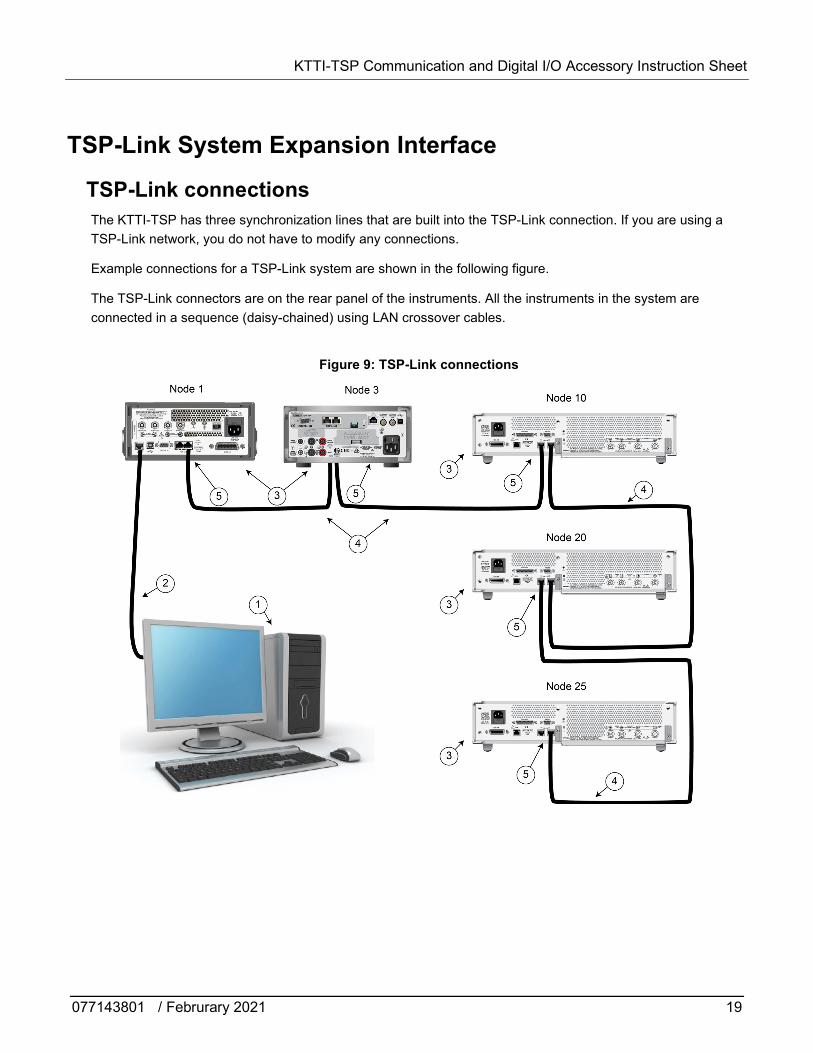
TSP-Link connections The KTTI-TSP has three synchronization lines that are built into the TSP-Link connection. If you are using a TSP-Link network, you do not have to modify any connections.
Example connections for a TSP-Link system are shown in the following figure.
The TSP-Link connectors are on the rear panel of the instruments. All the instruments in the system are connected in a sequence (daisy-chained) using LAN crossover cables.
Figure 9: TSP-Link connections
KTTI-TSP Communication and Digital I/O Accessory Instruction Sheet
20 077143801 / Februrary 2021
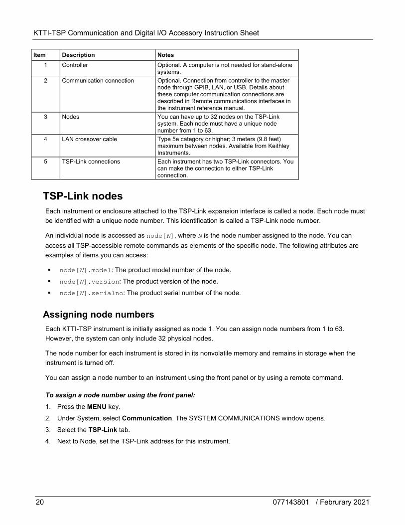
Item Description Notes 1 Controller Optional. A computer is not needed for stand-alone
systems. 2 Communication connection Optional. Connection from controller to the master
node through GPIB, LAN, or USB. Details about these computer communication connections are described in Remote communications interfaces in the instrument reference manual.
3 Nodes You can have up to 32 nodes on the TSP-Link system. Each node must have a unique node number from 1 to 63.
4 LAN crossover cable Type 5e category or higher; 3 meters (9.8 feet) maximum between nodes. Available from Keithley Instruments.
5 TSP-Link connections Each instrument has two TSP-Link connectors. You can make the connection to either TSP-Link connection.
TSP-Link nodes Each instrument or enclosure attached to the TSP-Link expansion interface is called a node. Each node must be identified with a unique node number. This identification is called a TSP-Link node number.
An individual node is accessed as node[N], where N is the node number assigned to the node. You can access all TSP-accessible remote commands as elements of the specific node. The following attributes are examples of items you can access:
node[N].model: The product model number of the node.
node[N].version: The product version of the node.
node[N].serialno: The product serial number of the node.
Assigning node numbers Each KTTI-TSP instrument is initially assigned as node 1. You can assign node numbers from 1 to 63. However, the system can only include 32 physical nodes.
The node number for each instrument is stored in its nonvolatile memory and remains in storage when the instrument is turned off.
You can assign a node number to an instrument using the front panel or by using a remote command.
To assign a node number using the front panel:
1. Press the MENU key.
2. Under System, select Communication. The SYSTEM COMMUNICATIONS window opens.
3. Select the TSP-Link tab.
4. Next to Node, set the TSP-Link address for this instrument.
KTTI-TSP Communication and Digital I/O Accessory Instruction Sheet
077143801 / Februrary 2021 21
To assign a node number using a remote command:
Set the tsplink.node attribute of the instrument:
tsplink.node = N
Where N = 1 to 63
To determine the node number of an instrument, you can read the tsplink.node attribute by sending the following command:
print(tsplink.node)
The above print command outputs the node number. For example, if the node number is 1, a 1 is displayed.
Master and subordinates In a TSP-Link system, one of the nodes (instruments) is the master node and the other nodes are the subordinate nodes. The master node in a TSP-Link system can control the other nodes (subordinates) in the system.
A TSP-Link system can be stand-alone or computer-based.
In a stand-alone system, scripts are loaded into the instruments. You can run a script from the front panel of any instrument (node) connected to the system. When a script is run, all nodes in the system go into remote operation. When the script is finished running, all the nodes in the system return to local operation, and the master/subordinate relationship between nodes is dissolved.
In a computer-based system, you can use a computer and a remote interface to communicate with a single node in the system. This node becomes the interface to the entire system. When a command is sent through this node, all nodes go into remote operation. The node that receives the command becomes the master and can control all other nodes, which become its subordinates. In a computer-based system, the master/subordinate relationship between nodes can only be dissolved by performing an abort operation. For more information about remote interfaces, see Remote communications interfaces.
When linking with earlier models of Keithley instruments, such as the Model 2600B, make sure to use the instrument that contains the KTTI-TSP as the master node and the earlier instruments as subordinates.
KTTI-TSP Communication and Digital I/O Accessory Instruction Sheet
22 077143801 / Februrary 2021
Initializing the TSP-Link system The TSP-Link system must be initialized after configuration changes. You need to initialize the system after you:
Turn off power or reboot any instrument in the system Change node numbers on any instrument in the system Rearrange or disconnect the TSP-Link cable connections between instruments
If initialization is not successful, you can check the event log for error messages that indicate the problem. Some typical problems include:
Two or more instruments in the system have the same node number There are no other instruments connected to the instrument performing the initialization One or more of the instruments in the system is turned off The actual number of nodes is less than the expected number
From the front panel:
1. Power on all instruments connected to the TSP-Link network.
2. Press the MENU key.
3. Under System, select Communication. The SYSTEM COMMUNICATIONS window opens.
4. Select the TSP-Link tab.
5. Select Initialize.
Using TSP commands:
To initialize the TSP-Link system, send the command:
tsplink.initialize()
To check the state of the TSP-Link system, send the command:
print(tsplink.state)
If initialization was successful, online is returned. If initialization was not successful, offline is returned.
Sending commands to TSP-Link nodes You can send remote commands to any instrument on the TSP-Link system by adding node[N]. to the beginning of the remote command, where N is the node number.
For example, to sound the beeper on node 10, you would send the command:
node[10].beeper.beep(2, 2400)
To send a command to the master, you can interact with it as if it were a single instrument.
KTTI-TSP Communication and Digital I/O Accessory Instruction Sheet
077143801 / Februrary 2021 23
Using the reset() command Most TSP-Link system operations target a single node in the system, but the reset() command affects the system as a whole by resetting all nodes to their default settings:
-- Reset all nodes in a TSP-Link system to their default state. reset()
Using the reset() command in a TSP-Link network differs from using the tsplink.initialize() command. The tsplink.initialize() command reinitializes the TSP-Link network and turns off the output of any TSP-linked instrument. It may change the state of individual nodes in the system.
Use node[N].reset() or localnode.reset() to reset only one of the nodes. The other nodes are not affected. The following programming example shows this type of reset operation with code that is run on node 1.
-- Reset node 1 only. node[1].reset() -- Reset the node you are connected to (in this case, node 1). localnode.reset() -- Reset node 4 only. node[4].reset()
Terminating scripts on the TSP-Link system You can terminate a script that is executing on a TSP-Link system.
To terminate an executing script and return all nodes to local control, send the following command:
abort
This dissolves the master/subordinate relationships between nodes.
From the front panel, you can abort a script by pressing the TRIGGER key for a few seconds and selecting Abort Trigger Model from the dialog box that is displayed.
Triggering using TSP-Link trigger lines The KTTI-TSP has three trigger lines that you can use for triggering, digital I/O, and to synchronize multiple instruments on a TSP-Link® network.
KTTI-TSP Communication and Digital I/O Accessory Instruction Sheet
24 077143801 / Februrary 2021
Using TSP-Link trigger lines for digital I/O Each trigger line is an open-drain signal. When using the TSP-Link® trigger lines for digital I/O, any node that sets the programmed line state to zero (0) causes all nodes to read 0 from the line state. This occurs regardless of the programmed line state of any other node. Refer to the table in the Digital I/O bit weighting (on page 16) topic for digital bit weight values.
Running simultaneous test scripts Running test scripts simultaneously improves functional testing, provides higher throughput, and expands system flexibility. You can use TSP-Link and TSP scripting to run simultaneous test scripts. You can also manage the resources that are allocated to test scripts that are running simultaneously.
In addition, you can use the data queue to do real-time communication between nodes on the TSP-Link system.
To run test scripts simultaneously, you can set up your TSP-Link network in one of the following configurations:
Multiple TSP-Link networks Single TSP-Link network with groups
Using groups to manage nodes on a TSP-Link system TSP-Link groups allow each group to run a different test script simultaneously. This method requires one TSP-Link network and a single remote connection to the computer that is connected to the master node.
A group can consist of one or more nodes. You must assign group numbers to each node using remote commands. If you do not assign a node to a group, it defaults to group 0, which will always be grouped with the master node (regardless of the group to which the master node is assigned).
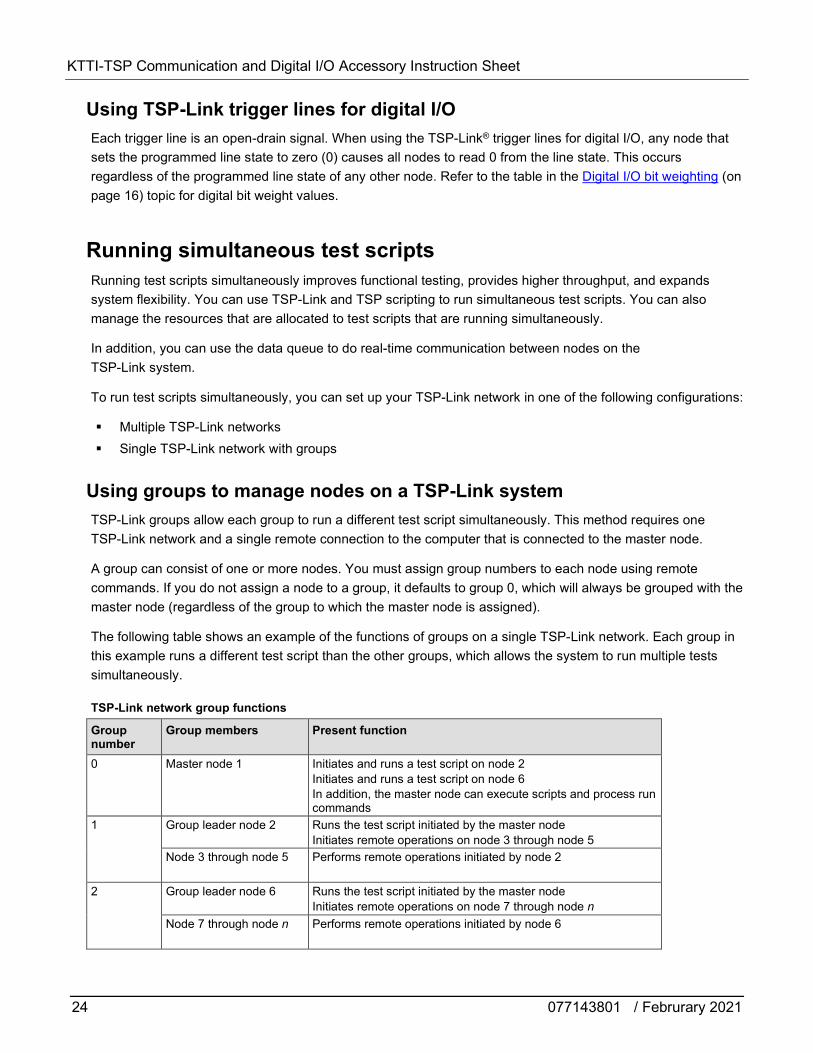
The following table shows an example of the functions of groups on a single TSP-Link network. Each group in this example runs a different test script than the other groups, which allows the system to run multiple tests simultaneously.
TSP-Link network group functions
Group number
Group members Present function
0 Master node 1 Initiates and runs a test script on node 2 Initiates and runs a test script on node 6 In addition, the master node can execute scripts and process run commands
1 Group leader node 2 Runs the test script initiated by the master node Initiates remote operations on node 3 through node 5
Node 3 through node 5 Performs remote operations initiated by node 2
2
Group leader node 6 Runs the test script initiated by the master node Initiates remote operations on node 7 through node n
Node 7 through node n Performs remote operations initiated by node 6
KTTI-TSP Communication and Digital I/O Accessory Instruction Sheet
077143801 / Februrary 2021 25
Master node overview You can assign the master node to any group. You can also include other nodes in the group that includes the master. Note that any nodes that are set to group 0 are automatically included in the group that contains the master node, regardless of the group that is assigned to the master node.
The master node is always the node that coordinates activity on the TSP-Link network.
The master node:
Is the only node that can use the execute() command on a remote node
Cannot initiate remote operations on any node in a remote group if any node in that remote group is performing an overlapped operation (a command that continues to operate after the command that initiated it has finished running)
Can execute the waitcomplete() command to wait for the group to which the master node belongs; to wait for another group; or to wait for all nodes on the TSP-Link network to complete overlapped operations (overlapped commands allow the execution of subsequent commands while device operations of the overlapped command are still in progress)
Group leader overview Each group has a dynamic group leader. The last node in a group that performs any operation initiated by the master node is the group leader.
The group leader:
Performs operations initiated by the master node Initiates remote operations on any node with the same group number Cannot initiate remote operations on any node with a different group number Can use the waitcomplete() command without a parameter to wait for all overlapped operations
running on nodes in the same group
Assigning groups Group numbers can range from zero (0) to 64. The default group number is 0. You can change the group number at any time. You can also add or remove a node to or from a group at any time.
Each time the power for a node is turned off, the group number for that node changes to 0.
The following example code dynamically assigns a node to a group:
-- Assign node 3 to group 1. node[3].tsplink.group = 1
KTTI-TSP Communication and Digital I/O Accessory Instruction Sheet
26 077143801 / Februrary 2021
Running test scripts and programs on remote nodes You can send the execute() command from the master node to initiate a test script and Lua code on a remote node. The execute() command places the remote node in the overlapped operation state. As a test script runs on the remote node, the master node continues to process other commands simultaneously.
Use the following code to send the execute() command for a remote node. The N parameter represents the node number that runs the test script (replace N with the node number).
To set the global variable "setpoint" on node N to 2.5: node[N].execute("setpoint = 2.5")
The following code demonstrates how to run a test script that is defined on the local node. For this example, scriptVar is defined on the local node, which is the node that initiates the code to run on the remote node. The local node must be the master node.
To run scriptVar on node N: node[N].execute(scriptVar.source)
The programming example below demonstrates how to run a test script that is defined on a remote node. For this example, scriptVar is defined on the remote node.
To run a script defined on the remote node: node[N].execute("scriptVar()")
It is recommended that you copy large scripts to a remote node to improve system performance.
KTTI-TSP Communication and Digital I/O Accessory Instruction Sheet
077143801 / Februrary 2021 27
Coordinating overlapped operations in remote groups All overlapped operations on all nodes in a group must have completed before the master node can send a command to the group. If you send a command to a node in a remote group when an overlapped operation is running on any node in that group, errors will occur.
You can execute the waitcomplete() command on the master node or group leader to wait for overlapped operations. The action of waitcomplete() depends on the parameters specified.
If you want to wait for completion of overlapped operations for:
All nodes in the local group: Use waitcomplete() without a parameter from the master node or group leader.
A specific group: Use waitcomplete(N) with a group number as the parameter from the master node. This option is not available for group leaders.
All nodes in the system: Use waitcomplete(0) from the master node. This option is not available for group leaders.
For additional information, refer to waitcomplete().
The following code shows two examples of using the waitcomplete() command from the master node:
-- Wait for each node in group N to complete all overlapped operations. waitcomplete(N) -- Wait for all groups on the TSP-Link network to complete overlapped operations. waitcomplete(0)
A group leader can issue the waitcomplete() command to wait for the local group to complete all overlapped operations.
The following code is an example of how to use the waitcomplete() command from a group leader:
-- Wait for all nodes in the local group to complete all overlapped operations. waitcomplete()

KTTI-TSP Communication and Digital I/O Accessory Instruction Sheet
28 077143801 / Februrary 2021
Using the data queue for real-time communication Nodes that are running test scripts at the same time can store data in the data queue for real-time communication. Each instrument has an internal data queue that uses the first-in, first-out (FIFO) structure to store data. You can use the data queue to post numeric values, strings, and tables.
Use the data queue commands to:
Share data between test scripts running in parallel Access data from a remote group or a local node on a TSP-Link network at any time
You cannot access the reading buffers or global variables from any node in a remote group while a node in that group is performing an overlapped operation. However, you can use the data queue to retrieve data from any node in a group that is performing an overlapped operation. In addition, the master node and the group leaders can use the data queue to coordinate activities.
Tables in the data queue consume one entry. When a node stores a table in the data queue, a copy of the data in the table is made. When the data is retrieved from the data queue, a new table is created on the node that is retrieving the data. The new table contains a separate copy of the data in the original table, with no references to the original table or any subtables.
You can access data from the data queue even if a remote group or a node has overlapped operations in process. See the dataqueue commands for more information.
KTTI-TSP Communication and Digital I/O Accessory Instruction Sheet
077143801 / Februrary 2021 29
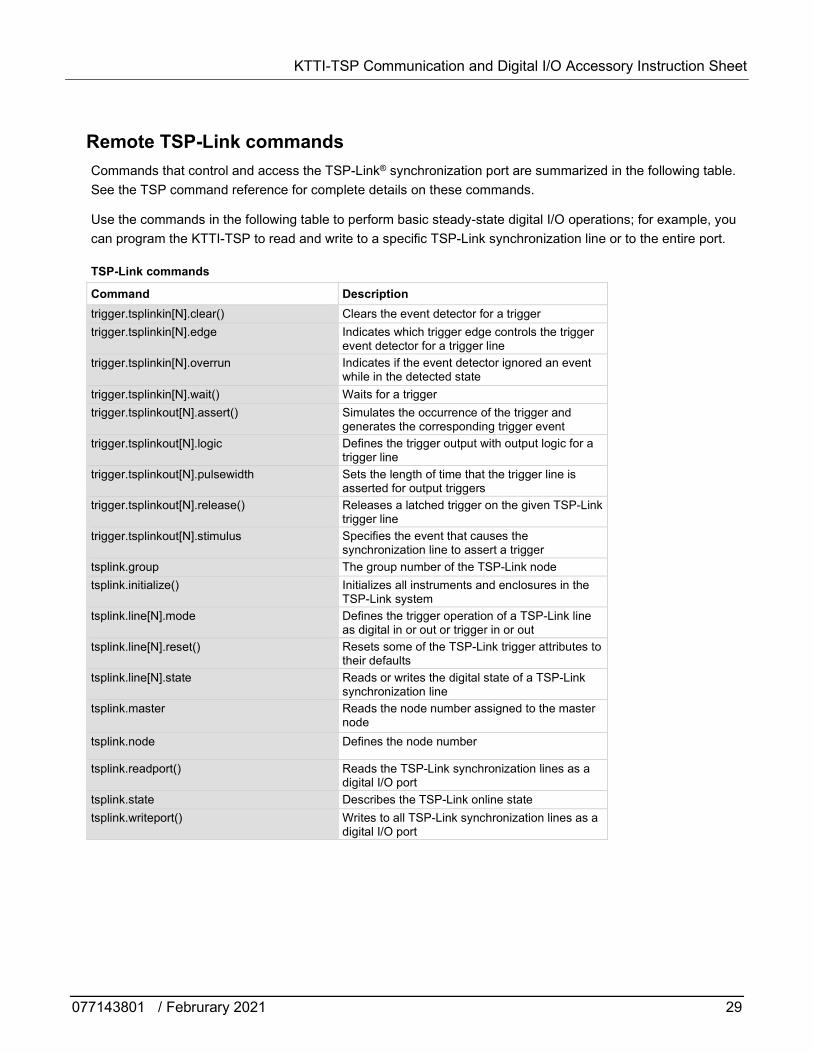
Remote TSP-Link commands Commands that control and access the TSP-Link® synchronization port are summarized in the following table. See the TSP command reference for complete details on these commands.
Use the commands in the following table to perform basic steady-state digital I/O operations; for example, you can program the KTTI-TSP to read and write to a specific TSP-Link synchronization line or to the entire port.
TSP-Link commands
Command Description trigger.tsplinkin[N].clear() Clears the event detector for a trigger trigger.tsplinkin[N].edge Indicates which trigger edge controls the trigger
event detector for a trigger line trigger.tsplinkin[N].overrun Indicates if the event detector ignored an event
while in the detected state trigger.tsplinkin[N].wait() Waits for a trigger trigger.tsplinkout[N].assert() Simulates the occurrence of the trigger and
generates the corresponding trigger event trigger.tsplinkout[N].logic Defines the trigger output with output logic for a
trigger line trigger.tsplinkout[N].pulsewidth Sets the length of time that the trigger line is
asserted for output triggers trigger.tsplinkout[N].release() Releases a latched trigger on the given TSP-Link
trigger line trigger.tsplinkout[N].stimulus Specifies the event that causes the
synchronization line to assert a trigger tsplink.group The group number of the TSP-Link node tsplink.initialize() Initializes all instruments and enclosures in the
TSP-Link system tsplink.line[N].mode Defines the trigger operation of a TSP-Link line
as digital in or out or trigger in or out tsplink.line[N].reset() Resets some of the TSP-Link trigger attributes to
their defaults tsplink.line[N].state Reads or writes the digital state of a TSP-Link
synchronization line tsplink.master Reads the node number assigned to the master
node tsplink.node Defines the node number
tsplink.readport() Reads the TSP-Link synchronization lines as a digital I/O port
tsplink.state Describes the TSP-Link online state tsplink.writeport() Writes to all TSP-Link synchronization lines as a
digital I/O port
KTTI-TSP Communication and Digital I/O Accessory Instruction Sheet
30 077143801 / Februrary 2021
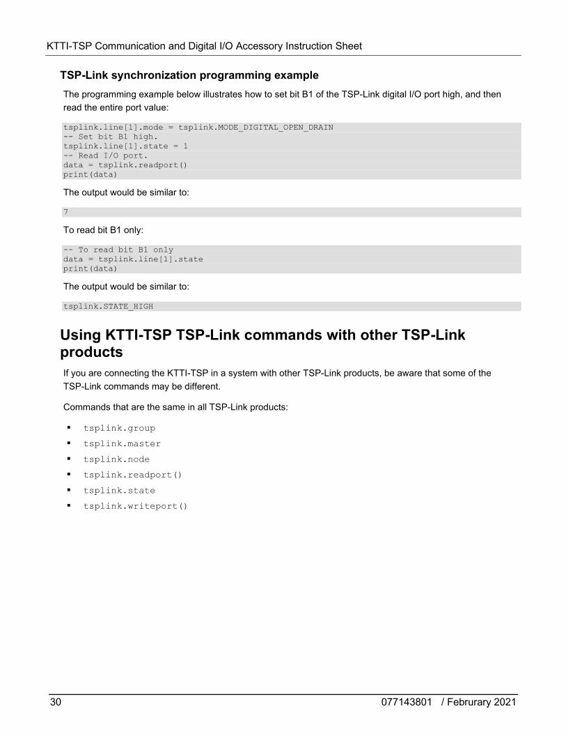
TSP-Link synchronization programming example The programming example below illustrates how to set bit B1 of the TSP-Link digital I/O port high, and then read the entire port value:
tsplink.line[1].mode = tsplink.MODE_DIGITAL_OPEN_DRAIN -- Set bit B1 high. tsplink.line[1].state = 1 -- Read I/O port. data = tsplink.readport() print(data)
The output would be similar to:
7
To read bit B1 only:
-- To read bit B1 only data = tsplink.line[1].state print(data)
The output would be similar to:
tsplink.STATE_HIGH
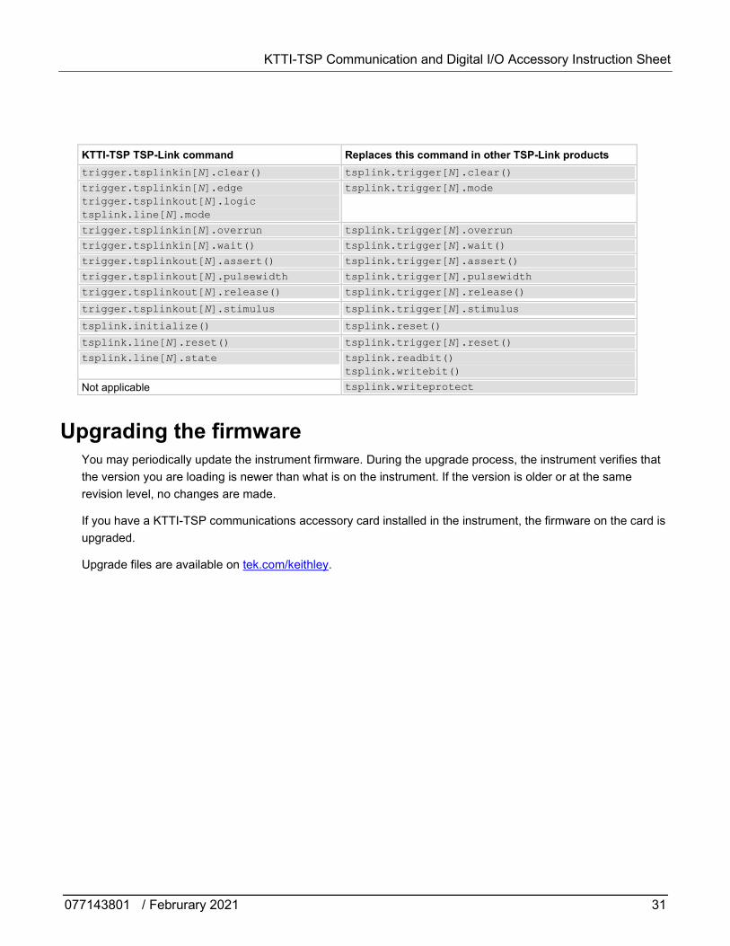
Using KTTI-TSP TSP-Link commands with other TSP-Link products If you are connecting the KTTI-TSP in a system with other TSP-Link products, be aware that some of the TSP-Link commands may be different.
Commands that are the same in all TSP-Link products:
tsplink.group tsplink.master tsplink.node tsplink.readport() tsplink.state tsplink.writeport()
KTTI-TSP Communication and Digital I/O Accessory Instruction Sheet
077143801 / Februrary 2021 31
KTTI-TSP TSP-Link command Replaces this command in other TSP-Link products trigger.tsplinkin[N].clear() tsplink.trigger[N].clear()
trigger.tsplinkin[N].edge trigger.tsplinkout[N].logic tsplink.line[N].mode
tsplink.trigger[N].mode
trigger.tsplinkin[N].overrun tsplink.trigger[N].overrun trigger.tsplinkin[N].wait() tsplink.trigger[N].wait()
trigger.tsplinkout[N].assert() tsplink.trigger[N].assert()
trigger.tsplinkout[N].pulsewidth tsplink.trigger[N].pulsewidth
trigger.tsplinkout[N].release() tsplink.trigger[N].release()
trigger.tsplinkout[N].stimulus tsplink.trigger[N].stimulus
tsplink.initialize() tsplink.reset()
tsplink.line[N].reset() tsplink.trigger[N].reset()
tsplink.line[N].state tsplink.readbit() tsplink.writebit()
Not applicable tsplink.writeprotect
Upgrading the firmware You may periodically update the instrument firmware. During the upgrade process, the instrument verifies that the version you are loading is newer than what is on the instrument. If the version is older or at the same revision level, no changes are made.
If you have a KTTI-TSP communications accessory card installed in the instrument, the firmware on the card is upgraded.
Upgrade files are available on tek.com/keithley.
32 077143801 / Februrary 2021
Safety precautions The following safety precautions should be observed before using this product and any associated instrumentation. Although some instruments and accessories would normally be used with nonhazardous voltages, there are situations where hazardous conditions may be present.
This product is intended for use by personnel who recognize shock hazards and are familiar with the safety precautions required to avoid possible injury. Read and follow all installation, operation, and maintenance information carefully before using the product. Refer to the user documentation for complete product specifications.
If the product is used in a manner not specified, the protection provided by the product warranty may be impaired.
The types of product users are:
Responsible body is the individual or group responsible for the use and maintenance of equipment, for ensuring that the equipment is operated within its specifications and operating limits, and for ensuring that operators are adequately trained.
Operators use the product for its intended function. They must be trained in electrical safety procedures and proper use of the instrument. They must be protected from electric shock and contact with hazardous live circuits.
Maintenance personnel perform routine procedures on the product to keep it operating properly, for example, setting the line voltage or replacing consumable materials. Maintenance procedures are described in the user documentation. The procedures explicitly state if the operator may perform them. Otherwise, they should be performed only by service personnel.
Service personnel are trained to work on live circuits, perform safe installations, and repair products. Only properly trained service personnel may perform installation and service procedures.
Keithley products are designed for use with electrical signals that are measurement, control, and data I/O connections, with low transient overvoltages, and must not be directly connected to mains voltage or to voltage sources with high transient overvoltages. Measurement Category II (as referenced in IEC 60664) connections require protection for high transient overvoltages often associated with local AC mains connections. Certain Keithley measuring instruments may be connected to mains. These instruments will be marked as category II or higher.
Unless explicitly allowed in the specifications, operating manual, and instrument labels, do not connect any instrument to mains.
Exercise extreme caution when a shock hazard is present. Lethal voltage may be present on cable connector jacks or test fixtures. The American National Standards Institute (ANSI) states that a shock hazard exists when voltage levels greater than 30 V RMS, 42.4 V peak, or 60 VDC are present. A good safety practice is to expect that hazardous voltage is present in any unknown circuit before measuring.
Operators of this product must be protected from electric shock at all times. The responsible body must ensure that operators are prevented access and/or insulated from every connection point. In some cases, connections must be exposed to potential human contact. Product operators in these circumstances must be trained to protect themselves from the risk of electric shock. If the circuit is capable of operating at or above 1000 V, no conductive part of the circuit may be exposed.
For maximum safety, do not touch the product, test cables, or any other instruments while power is applied to the circuit under test. ALWAYS remove power from the entire test system and discharge any capacitors before: connecting or disconnecting cables or jumpers, installing or removing switching cards, or making internal changes, such as installing or removing jumpers.
Do not touch any object that could provide a current path to the common side of the circuit under test or power line (earth) ground. Always make measurements with dry hands while standing on a dry, insulated surface capable of withstanding the voltage being measured.
For safety, instruments and accessories must be used in accordance with the operating instructions. If the instruments or accessories are used in a manner not specified in the operating instructions, the protection provided by the equipment may be impaired.
Do not exceed the maximum signal levels of the instruments and accessories. Maximum signal levels are defined in the specifications and operating information and shown on the instrument panels, test fixture panels, and switching cards.
Chassis connections must only be used as shield connections for measuring circuits, NOT as protective earth (safety ground) connections.
The WARNING heading in the user documentation explains hazards that might result in personal injury or death. Always read the associated information very carefully before performing the indicated procedure.
077143801 / Februrary 2021 33
The CAUTION heading in the user documentation explains hazards that could damage the instrument. Such damage may invalidate the warranty.
The CAUTION heading with the symbol in the user documentation explains hazards that could result in moderate or minor injury or damage the instrument. Always read the associated information very carefully before performing the indicated procedure. Damage to the instrument may invalidate the warranty.
Instrumentation and accessories shall not be connected to humans.
Before performing any maintenance, disconnect the line cord and all test cables.
To maintain protection from electric shock and fire, replacement components in mains circuits — including the power transformer, test leads, and input jacks — must be purchased from Keithley. Standard fuses with applicable national safety approvals may be used if the rating and type are the same. The detachable mains power cord provided with the instrument may only be replaced with a similarly rated power cord. Other components that are not safety-related may be purchased from other suppliers as long as they are equivalent to the original component (note that selected parts should be purchased only through Keithley to maintain accuracy and functionality of the product). If you are unsure about the applicability of a replacement component, call a Keithley office for information.
Unless otherwise noted in product-specific literature, Keithley instruments are designed to operate indoors only, in the following environment: Altitude at or below 2,000 m (6,562 ft); temperature 0 °C to 50 °C (32 °F to 122 °F); and pollution degree 1 or 2.
To clean an instrument, use a cloth dampened with deionized water or mild, water-based cleaner. Clean the exterior of the instrument only. Do not apply cleaner directly to the instrument or allow liquids to enter or spill on the instrument. Products that consist of a circuit board with no case or chassis (e.g., a data acquisition board for installation into a computer) should never require cleaning if handled according to instructions. If the board becomes contaminated and operation is affected, the board should be returned to the factory for proper cleaning/servicing.
Safety precaution revision as of June 2017.