Embed Size (px)
Citation preview
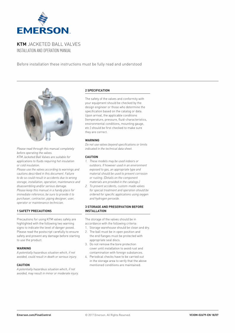
Please read through this manual completely before operating the valves.KTM Jacketed Ball Valves are suitable for applications to fluids requiring hot insulation or cold insulation.Please use the valves according to warnings and cautions described in this document. Failure to do so could result in accidents due to wrong storage, installation, operation, maintenance and disassembling and/or serious damage.Please keep this manual in a handy place for immediate reference; be sure to provide it to purchaser, contractor, piping designer, user, operator or maintenance technician.
KTM Jacketed ball valvesInstallatIon and operatIon manual
1 SafeTy precauTionS
Precautions for using ktM valves safely are highlighted with the following two warning signs to indicate the level of danger posed. Please read the postscript carefully to ensure safety and prevent any damage before starting to use the product.
WarningA potentially hazardous situation which, if not avoided, could result in death or serious injury.
cauTionA potentially hazardous situation which, if not avoided, may result in minor or moderate injury.
3 STorage and preServaTion before inSTallaTion
the storage of the valves should be in accordance with the following criteria:1. storage warehouse should be clean and dry.2. the ball must be in open position and
the end flanges must be protected with appropriate seal discs.
3. do not remove the bore protection cover until installation to avoid rust and contamination with foreign substances.
4. Periodical checks have to be carried out in the storage area to verify that the above mentioned conditions are maintained.
2 SpecificaTion
the safety of the valves and conformity with your equipment should be checked by the design engineer or those who determine the specification based on the catalog or data.Upon arrival, the applicable conditions (temperature, pressure, fluid-characteristics, environmental conditions, mounting gauge, etc.) should be first checked to make sure they are correct.
WarningDo not use valves beyond specifications or limits indicated in the technical data sheet.
cauTion1. These models may be used indoors or
outdoors. If however used in an environment exposed to gas, an appropriate type and material should be used to prevent corrosion or rusting. (Details on the component materials are provided in the catalogs.)
2. To prevent accidents, custom-made valves for special treatment and operation should be ordered for specific applications using oxygen and hydrogen peroxide.
vcioM-02679-en 18/07emerson.com/finalcontrol © 2017 emerson. all Rights Reserved.
before installation these instructions must be fully read and understood
2
½ 1½ -¾ 1½ -1 2 -1½ 2½ -2 3 -2½ 4 -3 6 44 8 65 8 -6 10 88 14 1010 - 14
15 40 -20 40 -25 50 -40 65 -50 80 -65 100 -80 150 100100 200 150125 200 -150 250 200200 350 250250 - 350
5 inSTallaTion
the following instructions will make for a satisfactory and long life of the valve.1. Remove the valve from the shipping package
(box or pallet) carefully to avoid any damage to the valve and actuator (plus accessories where applicable).
2. confirm that the materials of construction listed on the valve nameplates are appropriate for the intended service for and according to specification. When in doubt, contact ktM or your local emerson facility.
3. define the preferred mounting orientation with respect to the system pressure. Where applicable, the arrow on the body helps to identify the upstream side (high pressure) and downstream side (low pressure).
4. Fasteners like bolts and nuts at each connecting portion on the valve should be checked and retightened in case they were loosened due to shock during transportation. When tightening nuts, use a closed wrench for safety.
5. before installation, the protection cover on the bore must be removed.
6. Manually operated valves, may be installed on pipes at any angle, horizontally, vertically or any other direction. It is however recommended they are installed to facilitate maintenance, handling, and nozzle, drain position.
7. Maintenance space must be provided.8. the flange size of both side of the valve is
different from the nominal size of the valve as shown right. ensure correct fitting of the flange size before installation.
flange Size (MeTric)valve size flange size (mm)dn full bore reduced bore
flange Size (iMperial)valve size flange size (inch)npS full bore reduced bore
4 TranSporTaTion
Warning1. When handling valves, the correct equipment
and accessories (slings, fasteners, hooks etc.) must be sized and selected, taking into consideration the individual and/or overall valves weight indicated in the packing list and/or delivery note.
2. Lifting and handling must be done only by qualified personnel. Improper hoisting can cause valve deformation or damage from dropping the valve.
3. Do not lift the valves by using lifting points or lugs on the actuator, as these lifting points/lugs are for the actuator only.
4. Do not lift the valve by its hand-lever as these levers are not designed to take the load of the whole valve. Doing so may cause the lever to brake off or be disconnected from the valve, resulting in possible valve damage or a person’s injury.
cauTion1. The ball valves are delivered with the ball in
full-open position and should be stored as they are. Keeping the ball in other positions, incl. half-open position, for an extended period of time could cause seat leakage.
2. Do not place consignment package directly on the ground.
3. Do not expose consignment packages to the rain/wind or directly to the sun.
4. Storage in an open area for a limited period can be considered only if the valves have appropriate packing (packed in cases covered with vinyl sheets protecting from rain, wind, dust etc).
5. Store in a dry and well ventilated condition.6. If storage is anticipated for an extended period,
the desiccant bags (if supplied) should be changed every six months.
KTM Jacketed ball valvesInstallatIon and operatIon manual
5. Avoid lifting over people’s heads, equipment or anything else that can possibly be damaged or caused injury in the event that the lifted load falls off the handling equipment.
6. All local safety regulations must be observed and complied with at all times.
3
①
⑧
③
⑤
⑥④
⑦②
cauTion1. Ensure that there are no solid objects such as
pieces of wood, plastic or packing materials within the valve or on the valve seat. It is recommended to flush pipes before installing the valve. If this is not possible, the installed valve must be in its open position before flushing takes place.
2. Unless otherwise recommended by KTM, the valves should be installed with the ball in open position to ensure that the seat rings are not damaged during installation.
3. Use appropriate gaskets which comply with standards or specifications.
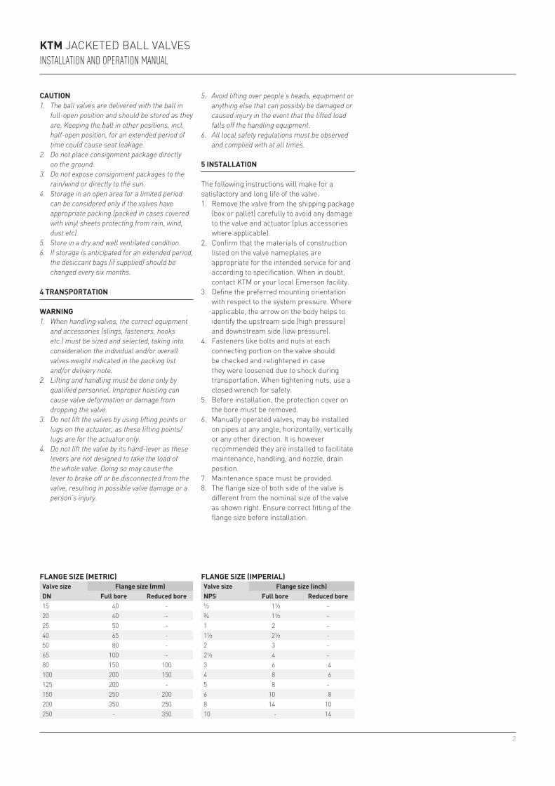
4. Tighten the flange bolts with a closed wrench; using a ‘crisscross’ pattern that alternately tightens the bolts located 180 degrees apart. (see Figure 1) Unequal partial tightening places stress on lined pipes which may damage the flange or produce excessive operation torque.
FIgURe 1tightening of bolt
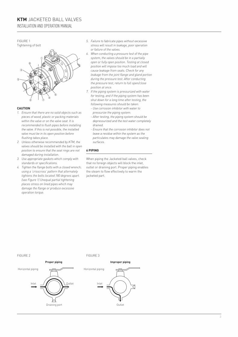
6 piping
When piping the Jacketed ball valves, check that no foreign objects will block the inlet, outlet or draining port. Proper piping enables the steam to flow effectively to warm the jacketed part.
proper piping
Horizontal piping
Inlet Outlet
draining port
improper piping
Horizontal piping
Inlet
Outlet
FIgURe 2 FIgURe 3
KTM Jacketed ball valvesInstallatIon and operatIon manual
5. Failure to fabricate pipes without excessive stress will result in leakage, poor operation or failure of the valves.
6. When conducting a pressure test of the pipe system, the valves should be in a partially open or fully open position. Testing at closed position will impose too much load and will cause leakage from seats. Check for any leakage from the joint flange and gland portion during the pressure test. After conducting the pressure test, return to full open/close position at once.
7. If the piping system is pressurized with water for testing, and if the piping system has been shut down for a long time after testing, the following measures should be taken:
- Use corrosion inhibitor with water to pressurize the piping system.
- After testing, the piping system should be depressurized and the test water completely drained.
- Ensure that the corrosion inhibitor does not leave a residue within the system as the particulates may damage the valve sealing surfaces.
4
11.5
25
2315
4.5
ød0
ød
l
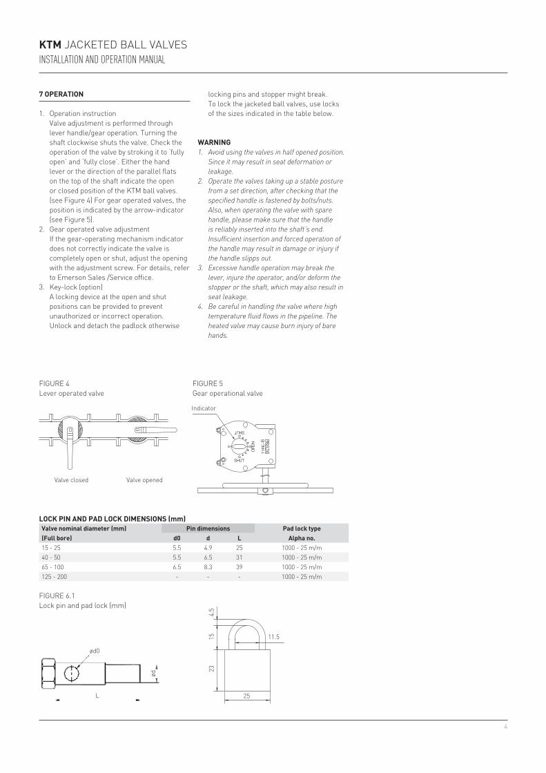
15 - 25 5.5 4.9 25 1000 - 25 m/m40 - 50 5.5 6.5 31 1000 - 25 m/m65 - 100 6.5 8.3 39 1000 - 25 m/m125 - 200 - - - 1000 - 25 m/m
7 operaTion
1. Operation instruction valve adjustment is performed through
lever handle/gear operation. turning the shaft clockwise shuts the valve. check the operation of the valve by stroking it to ‘fully open’ and ‘fully close’. either the hand lever or the direction of the parallel flats on the top of the shaft indicate the open or closed position of the ktM ball valves. (see Figure 4) For gear operated valves, the position is indicated by the arrow-indicator (see Figure 5).
2. gear operated valve adjustment If the gear-operating mechanism indicator
does not correctly indicate the valve is completely open or shut, adjust the opening with the adjustment screw. For details, refer to emerson sales /service office.
3. key-lock (option) a locking device at the open and shut
positions can be provided to prevent unauthorized or incorrect operation. Unlock and detach the padlock otherwise
Indicator
FIgURe 4lever operated valve
FIgURe 5gear operational valve
valve closed valve opened
Warning1. Avoid using the valves in half opened position.
Since it may result in seat deformation or leakage.
2. Operate the valves taking up a stable posture from a set direction, after checking that the specified handle is fastened by bolts/nuts. Also, when operating the valve with spare handle, please make sure that the handle is reliably inserted into the shaft’s end. Insufficient insertion and forced operation of the handle may result in damage or injury if the handle slipps out.
3. Excessive handle operation may break the lever, injure the operator, and/or deform the stopper or the shaft, which may also result in seat leakage.
4. Be careful in handling the valve where high temperature fluid flows in the pipeline. The heated valve may cause burn injury of bare hands.
locK pin and pad locK diMenSionS (mm)valve nominal diameter (mm) pin dimensions pad lock type(full bore) d0 d l alpha no.
FIgURe 6.1lock pin and pad lock (mm)
KTM Jacketed ball valvesInstallatIon and operatIon manual
locking pins and stopper might break. to lock the jacketed ball valves, use locks
of the sizes indicated in the table below.
5
0.453
0.984
0.90
60.
591
0.17
7
ød0
ød
l
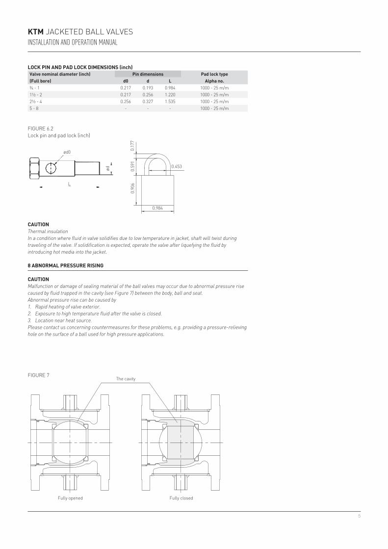
¾ - 1 0.217 0.193 0.984 1000 - 25 m/m1½ - 2 0.217 0.256 1.220 1000 - 25 m/m2½ - 4 0.256 0.327 1.535 1000 - 25 m/m5 - 8 - - - 1000 - 25 m/m
FIgURe 6.2lock pin and pad lock (inch)
cauTionThermal insulationIn a condition where fluid in valve solidifies due to low temperature in jacket, shaft will twist during traveling of the valve. If solidification is expected, operate the valve after liquefying the fluid by introducing hot media into the jacket.
Fully opened Fully closed
the cavityFIgURe 7
8 abnorMal preSSure riSing
cauTionMalfunction or damage of sealing material of the ball valves may occur due to abnormal pressure rise caused by fluid trapped in the cavity (see Figure 7) between the body, ball and seat.Abnormal pressure rise can be caused by1. Rapid heating of valve exterior.2. Exposure to high temperature fluid after the valve is closed.3. Location near heat source.Please contact us concerning countermeasures for these problems, e.g. providing a pressure-relieving hole on the surface of a ball used for high pressure applications.
KTM Jacketed ball valvesInstallatIon and operatIon manual
locK pin and pad locK diMenSionS (inch)valve nominal diameter (inch) pin dimensions pad lock type(full bore) d0 d l alpha no.
6
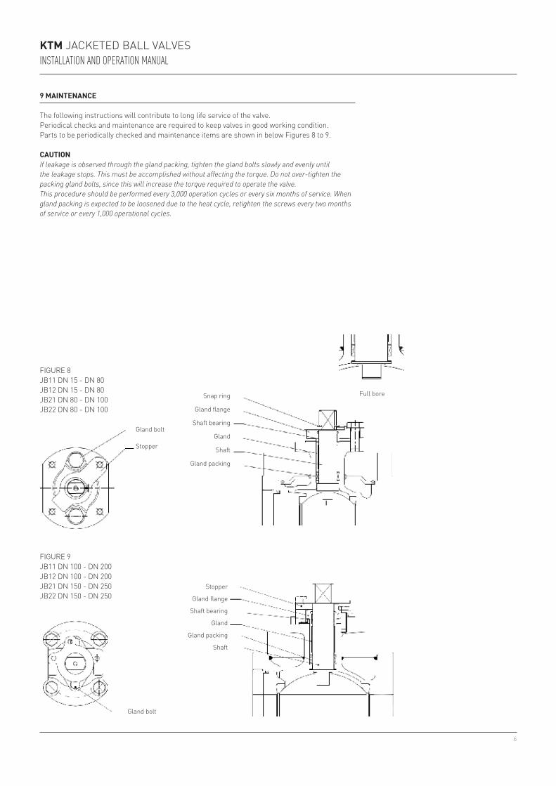
FIgURe 8Jb11 dN 15 - dN 80Jb12 dN 15 - dN 80Jb21 dN 80 - dN 100Jb22 dN 80 - dN 100
FIgURe 9Jb11 dN 100 - dN 200Jb12 dN 100 - dN 200Jb21 dN 150 - dN 250Jb22 dN 150 - dN 250
gland bolt
stopper
snap ring
gland flange
shaft bearing
gland
shaft
gland packing
gland bolt
stopper
gland flange
shaft bearing
gland
gland packing
shaft
9 MainTenance
the following instructions will contribute to long life service of the valve.Periodical checks and maintenance are required to keep valves in good working condition. Parts to be periodically checked and maintenance items are shown in below Figures 8 to 9.
cauTionIf leakage is observed through the gland packing, tighten the gland bolts slowly and evenly until the leakage stops. This must be accomplished without affecting the torque. Do not over-tighten the packing gland bolts, since this will increase the torque required to operate the valve.This procedure should be performed every 3,000 operation cycles or every six months of service. When gland packing is expected to be loosened due to the heat cycle, retighten the screws every two months of service or every 1,000 operational cycles.
Full bore
KTM Jacketed ball valvesInstallatIon and operatIon manual
7
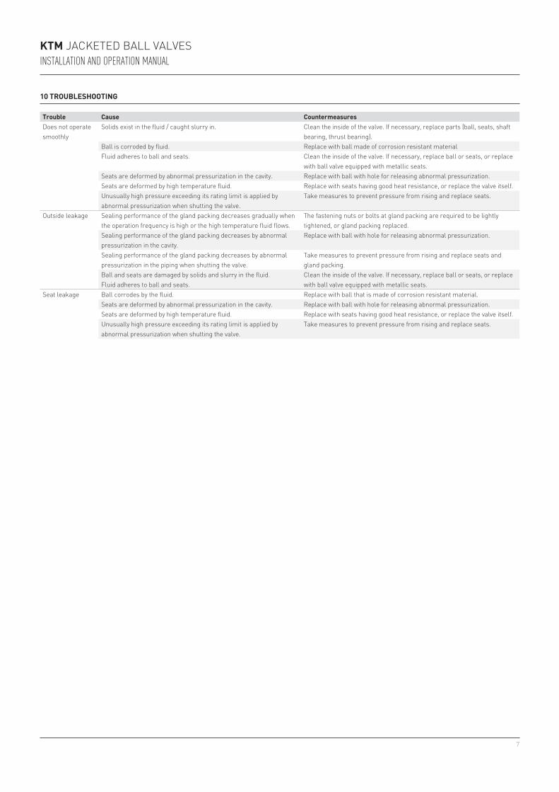
Trouble cause countermeasuresdoes not operate smoothly
solids exist in the fluid / caught slurry in. clean the inside of the valve. If necessary, replace parts (ball, seats, shaft bearing, thrust bearing).
ball is corroded by fluid. Replace with ball made of corrosion resistant materialFluid adheres to ball and seats. clean the inside of the valve. If necessary, replace ball or seats, or replace
with ball valve equipped with metallic seats.seats are deformed by abnormal pressurization in the cavity. Replace with ball with hole for releasing abnormal pressurization.seats are deformed by high temperature fluid. Replace with seats having good heat resistance, or replace the valve itself.Unusually high pressure exceeding its rating limit is applied by abnormal pressurization when shutting the valve.
take measures to prevent pressure from rising and replace seats.
Outside leakage sealing performance of the gland packing decreases gradually when the operation frequency is high or the high temperature fluid flows.
the fastening nuts or bolts at gland packing are required to be lightly tightened, or gland packing replaced.
sealing performance of the gland packing decreases by abnormal pressurization in the cavity.
Replace with ball with hole for releasing abnormal pressurization.
sealing performance of the gland packing decreases by abnormal pressurization in the piping when shutting the valve.
take measures to prevent pressure from rising and replace seats and gland packing.
ball and seats are damaged by solids and slurry in the fluid. clean the inside of the valve. If necessary, replace ball or seats, or replace with ball valve equipped with metallic seats.Fluid adheres to ball and seats.
seat leakage ball corrodes by the fluid. Replace with ball that is made of corrosion resistant material.seats are deformed by abnormal pressurization in the cavity. Replace with ball with hole for releasing abnormal pressurization.seats are deformed by high temperature fluid. Replace with seats having good heat resistance, or replace the valve itself.Unusually high pressure exceeding its rating limit is applied by abnormal pressurization when shutting the valve.
take measures to prevent pressure from rising and replace seats.
KTM Jacketed ball valvesInstallatIon and operatIon manual
10 TroubleShooTing
8
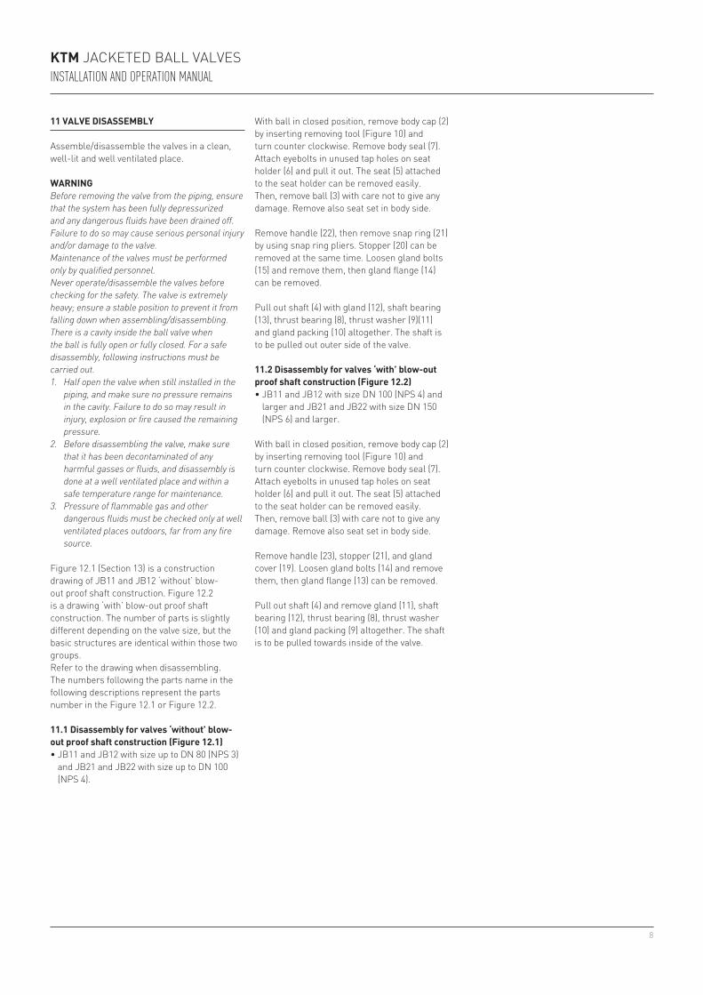
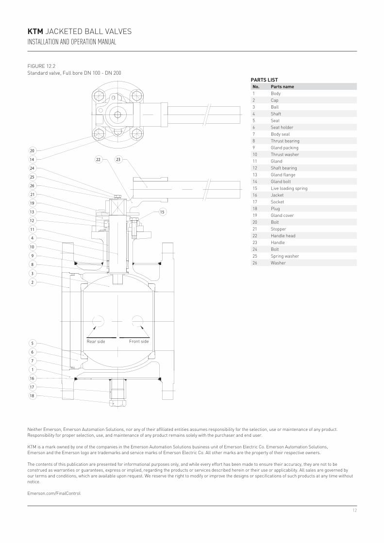
Figure 12.1 (section 13) is a construction drawing of Jb11 and Jb12 ‘without’ blow-out proof shaft construction. Figure 12.2 is a drawing ‘with’ blow-out proof shaft construction. the number of parts is slightly different depending on the valve size, but the basic structures are identical within those two groups.Refer to the drawing when disassembling. the numbers following the parts name in the following descriptions represent the parts number in the Figure 12.1 or Figure 12.2.
11.1 disassembly for valves ‘without’ blow-out proof shaft construction (figure 12.1)• Jb11 and Jb12 with size up to dN 80 (NPs 3)
and Jb21 and Jb22 with size up to dN 100 (NPs 4).
11 valve diSaSSeMbly
assemble/disassemble the valves in a clean, well-lit and well ventilated place.
WarningBefore removing the valve from the piping, ensure that the system has been fully depressurized and any dangerous fluids have been drained off. Failure to do so may cause serious personal injury and/or damage to the valve.Maintenance of the valves must be performed only by qualified personnel.Never operate/disassemble the valves before checking for the safety. The valve is extremely heavy; ensure a stable position to prevent it from falling down when assembling/disassembling.There is a cavity inside the ball valve when the ball is fully open or fully closed. For a safe disassembly, following instructions must be carried out.1. Half open the valve when still installed in the
piping, and make sure no pressure remains in the cavity. Failure to do so may result in injury, explosion or fire caused the remaining pressure.
2. Before disassembling the valve, make sure that it has been decontaminated of any harmful gasses or fluids, and disassembly is done at a well ventilated place and within a safe temperature range for maintenance.
3. Pressure of flammable gas and other dangerous fluids must be checked only at well ventilated places outdoors, far from any fire source.
KTM Jacketed ball valvesInstallatIon and operatIon manual
With ball in closed position, remove body cap (2) by inserting removing tool (Figure 10) and turn counter clockwise. Remove body seal (7). attach eyebolts in unused tap holes on seat holder (6) and pull it out. the seat (5) attached to the seat holder can be removed easily. then, remove ball (3) with care not to give any damage. Remove also seat set in body side.
Remove handle (22), then remove snap ring (21) by using snap ring pliers. stopper (20) can be removed at the same time. loosen gland bolts (15) and remove them, then gland flange (14) can be removed.
Pull out shaft (4) with gland (12), shaft bearing (13), thrust bearing (8), thrust washer (9)(11) and gland packing (10) altogether. the shaft is to be pulled out outer side of the valve.
11.2 disassembly for valves ‘with’ blow-out proof shaft construction (figure 12.2)• Jb11 and Jb12 with size dN 100 (NPs 4) and
larger and Jb21 and Jb22 with size dN 150 (NPs 6) and larger.
With ball in closed position, remove body cap (2) by inserting removing tool (Figure 10) and turn counter clockwise. Remove body seal (7). attach eyebolts in unused tap holes on seat holder (6) and pull it out. the seat (5) attached to the seat holder can be removed easily. then, remove ball (3) with care not to give any damage. Remove also seat set in body side.
Remove handle (23), stopper (21), and gland cover (19). loosen gland bolts (14) and remove them, then gland flange (13) can be removed.
Pull out shaft (4) and remove gland (11), shaft bearing (12), thrust bearing (8), thrust washer (10) and gland packing (9) altogether. the shaft is to be pulled towards inside of the valve.
9
a
a
bb
c
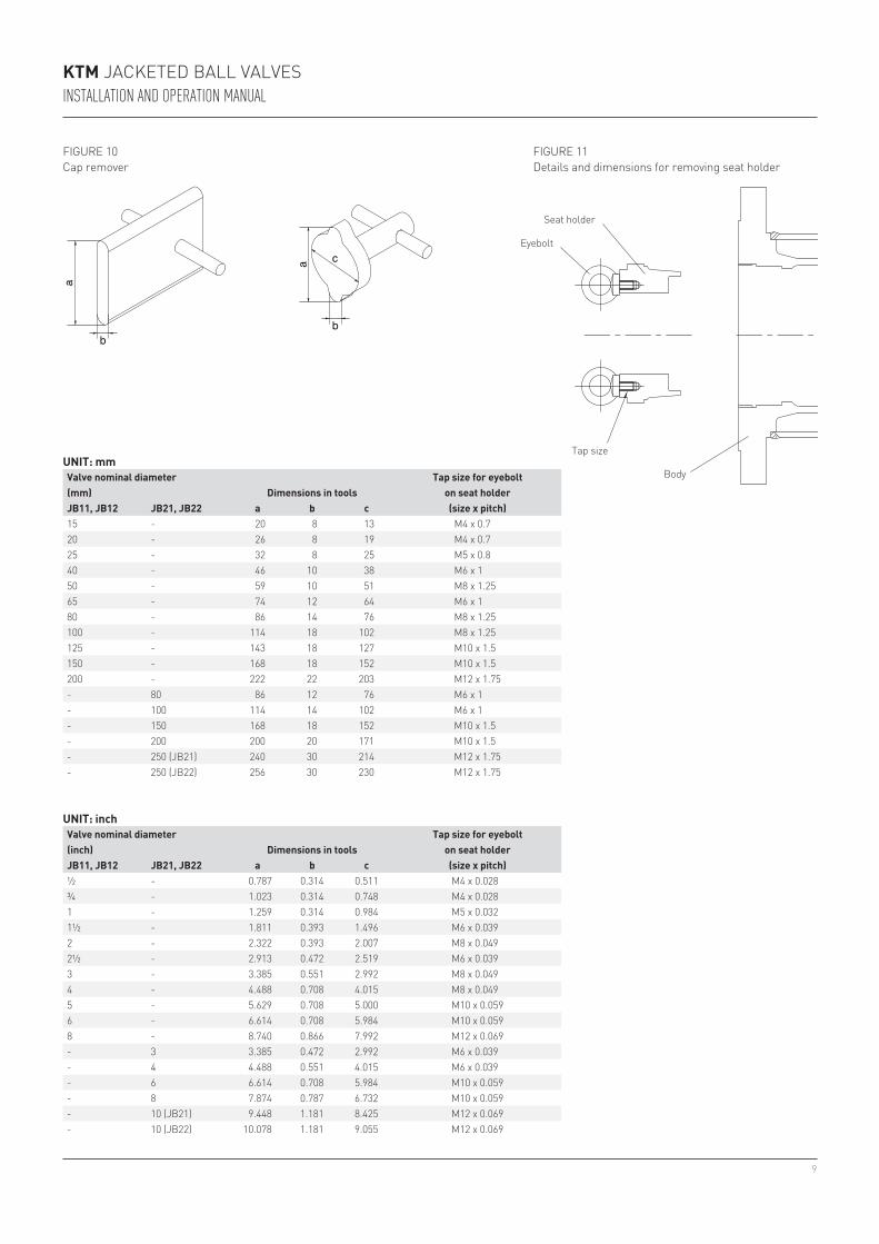
½ - 0.787 0.314 0.511 M4 x 0.028¾ - 1.023 0.314 0.748 M4 x 0.0281 - 1.259 0.314 0.984 M5 x 0.0321½ - 1.811 0.393 1.496 M6 x 0.0392 - 2.322 0.393 2.007 M8 x 0.0492½ - 2.913 0.472 2.519 M6 x 0.0393 - 3.385 0.551 2.992 M8 x 0.0494 - 4.488 0.708 4.015 M8 x 0.0495 - 5.629 0.708 5.000 M10 x 0.0596 - 6.614 0.708 5.984 M10 x 0.0598 - 8.740 0.866 7.992 M12 x 0.069- 3 3.385 0.472 2.992 M6 x 0.039- 4 4.488 0.551 4.015 M6 x 0.039- 6 6.614 0.708 5.984 M10 x 0.059- 8 7.874 0.787 6.732 M10 x 0.059- 10 (Jb21) 9.448 1.181 8.425 M12 x 0.069- 10 (Jb22) 10.078 1.181 9.055 M12 x 0.069
15 - 20 8 13 M4 x 0.720 - 26 8 19 M4 x 0.725 - 32 8 25 M5 x 0.840 - 46 10 38 M6 x 150 - 59 10 51 M8 x 1.2565 - 74 12 64 M6 x 180 - 86 14 76 M8 x 1.25100 - 114 18 102 M8 x 1.25125 - 143 18 127 M10 x 1.5150 - 168 18 152 M10 x 1.5200 - 222 22 203 M12 x 1.75- 80 86 12 76 M6 x 1- 100 114 14 102 M6 x 1- 150 168 18 152 M10 x 1.5- 200 200 20 171 M10 x 1.5- 250 (Jb21) 240 30 214 M12 x 1.75- 250 (Jb22) 256 30 230 M12 x 1.75
seat holder
eyebolt
tap size
body
FIgURe 11details and dimensions for removing seat holder
FIgURe 10cap remover
uniT: mmvalve nominal diameter
dimensions in toolsTap size for eyebolt
on seat holder(mm)Jb11, Jb12 Jb21, Jb22 a b c (size x pitch)
uniT: inchvalve nominal diameter
dimensions in toolsTap size for eyebolt
on seat holder(inch)Jb11, Jb12 Jb21, Jb22 a b c (size x pitch)
KTM Jacketed ball valvesInstallatIon and operatIon manual
10
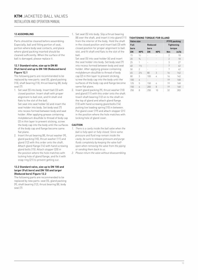
15 ½ - - 2 1820 ¾ - - 2 1825 1 - - 3 2740 1½ - - 7 6250 2 - - 7 6265 2½ 80 3 16 14280 3 100 4 16 142100 4 - - 19 168125 5 150 6 19 168150 6 200 8 19 168250 8 250 10 32 283
12 aSSeMbling
Parts should be cleaned before assembling. especially, ball and fitting portion of seat, portion where body seal contacts, and place where gland packing inserted should be cleaned sufficiently. When the surface of the ball is damaged, please replace it.
12.1 Standard valve, size up to dn 80 (full bore) and up to dn 100 (reduced bore) figure 12.1the following parts are recommended to be replaced by new parts: seat (5), gland packing (10), shaft bearing (13), thrust bearing (8), body seal (7)1. set seat (5) into body. Insert ball (3) with
closed position. Insert shaft with proper alignment to ball slot, and fit shaft end flats to the slot of the ball.
set seat into seat holder (6) and insert the seat holder into body. set body seal (7) into recess formed between body and seat holder. after applying grease containing molybdenum disulfide to thread of body cap (2) in thin layer to prevent sticking, screw the body cap into the body until the surfaces of the body cap and flange become same flat plane.
2. Insert thrust bearing (8), thrust washer (9), gland packing (10), thrust washer (11) and gland (12) with this order onto the shaft. attach gland flange (14) with hand screwing gland bolts (15). attach stopper (20) in the position where the hole matches with locking hole of gland flange, and fix it with snap ring (21) to prevent getting out.
12.2 Standard valve, size up to dn 100 and larger (full bore) and dn 150 and larger (reduced bore) figure 12.2the following parts are recommended to be replaced by new parts: seat (5), gland packing (9), shaft bearing (12), thrust bearing (8), body seal (7)
cauTion1. There is a cavity inside the ball valve when the
ball is fully open or fully closed. Since some pressure and fluid may remain inside the cavity, be sure to release pressure and purge fluids completely by keeping the valve half-open when removing the valve from the piping or sending them back to us.
2. Please return the valve without disassembling.
TighTening Torque for glandvalve size pTfe packingfull bore
reduced bore
Tightening torque
dn npS dn npS nm in/lb
KTM Jacketed ball valvesInstallatIon and operatIon manual
1. set seat (5) into body. slip a thrust bearing (8) over the shaft, and insert it into gland (11) from the interior of the body. Hold the shaft in the closed position and insert ball (3) with closed position for proper alignment to ball slot, and fit shaft end flats to the slot of the ball.
set seat (5) into seat holder (6) and insert the seat holder into body. set body seal (7) into recess formed between body and seat holder. after applying grease containing molybdenum disulfide to thread of body cap (2) in thin layer to prevent sticking, screw the body cap into the body until the surfaces of the body cap and flange become same flat plane.
2. Insert gland packing (9), thrust washer (10) and gland (11) with this order onto the shaft. Insert shaft bearing (12) on to the shaft on the top of gland and attach gland flange (13) with hand screwing gland bolts (14) putting live loading spring (15) in between. Put gland cover (19) and attach stopper (21) in the position where the hole matches with locking hole of gland cover.
11
1
19
18
6
7
17
2
5
3
8
9
10
4
12
13
14
20
21
22
11
23
25
24
16
15
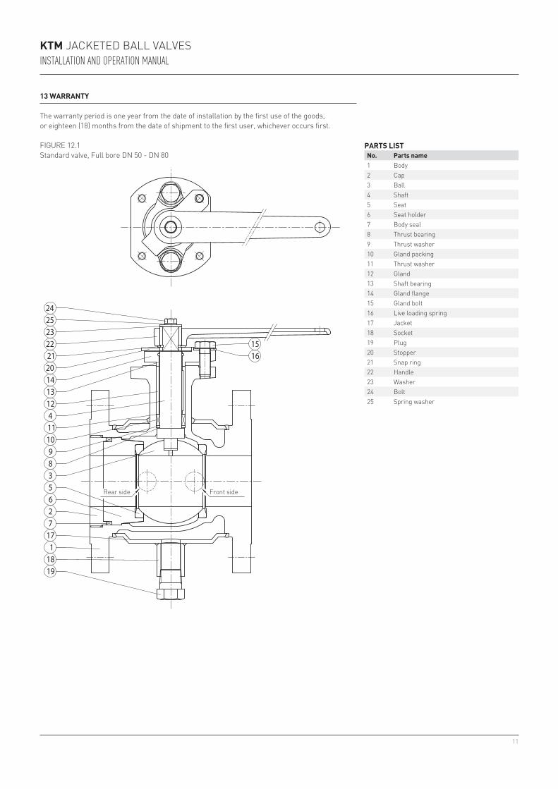
13 WarranTy
the warranty period is one year from the date of installation by the first use of the goods, or eighteen (18) months from the date of shipment to the first user, whichever occurs first.
FIgURe 12.1standard valve, Full bore dN 50 - dN 80
parTS liSTno. parts name1 body2 cap3 ball4 shaft5 seat6 seat holder7 body seal8 thrust bearing9 thrust washer10 gland packing11 thrust washer12 gland13 shaft bearing14 gland flange15 gland bolt16 live loading spring17 Jacket18 socket19 Plug20 stopper21 snap ring22 Handle23 Washer24 bolt25 spring washer
Front sideRear side
KTM Jacketed ball valvesInstallatIon and operatIon manual
12
18
17
16
1
7
6
5
2
3
8
9
10
4
11
12
13
19
21
26
25
24
14 22 23
20
15
parTS liSTno. parts name1 body2 cap3 ball4 shaft5 seat6 seat holder7 body seal8 thrust bearing9 gland packing10 thrust washer11 gland12 shaft bearing13 gland flange14 gland bolt15 live loading spring16 Jacket17 socket18 Plug19 gland cover20 bolt21 stopper22 Handle head23 Handle24 bolt25 spring washer26 Washer
FIgURe 12.2standard valve, Full bore dN 100 - dN 200
Front sideRear side
KTM Jacketed ball valvesInstallatIon and operatIon manual
Neither emerson, emerson automation solutions, nor any of their affiliated entities assumes responsibility for the selection, use or maintenance of any product. Responsibility for proper selection, use, and maintenance of any product remains solely with the purchaser and end user.
ktM is a mark owned by one of the companies in the emerson automation solutions business unit of emerson electric co. emerson automation solutions, emerson and the emerson logo are trademarks and service marks of emerson electric co. all other marks are the property of their respective owners.
the contents of this publication are presented for informational purposes only, and while every effort has been made to ensure their accuracy, they are not to be construed as warranties or guarantees, express or implied, regarding the products or services described herein or their use or applicability. all sales are governed by our terms and conditions, which are available upon request. We reserve the right to modify or improve the designs or specifications of such products at any time without notice.
emerson.com/Finalcontrol