Embed Size (px)
Citation preview

KILEWS JAPAN CO., LTD.
���� KTM-15
���� KTM-150
DIGITAL TORQUE METER INSTRUCTION MANUAL

1
Operation Manual for Digital Torque Meter Model: KTM -150/KTM-15
1、、、、Caution for safety � Keep work area always clean.
Cluttered areas and benches may cause injuries.
� Consider work area environment.
Do not use torque meter in the rain or in the damp or wet place. Use the product at a place left at
constant temperature (about 24℃). Keep work place well lighted.
Do not use or charge the product in presence of flammable liquids or gases.
� Keep children away.
Keep any person other than the operator(s) away from work area.
� Dress properly.
Do not wear loose clothing or jewelry, which may be caught in moving parts.
� Work with the most care.
When using the product, carefully work, with consideration to how to handle, how to work, work
environment, etc.
� Fix main body firmly.
When operated for measuring a large torque, use clamps or vises, etc. It is not only more safe
than holding by hand but also makes it possible to grip the screwdriver by both hands.
� Do not apply a torque exceeding the permissible load.
If applied beyond the permissible load, it may cause damage to the sensor, resulting in accident
or injury.
� Do not disassembly, shock and vibrate this product.
Avoid disassembling the product that is a precise instrument. If the torque meter is damaged by
excessive shock or vibration, the product may not only show the full performance but also result
in accident or injury.
� Caution to electric shock.
Do not touch power plug by wet hand. It may cause electric shock.
� For charging the battery be sure to use only exclusive charger.
Using an original charger other than compatible may cause fire or injury.
� Charge properly.
Charge on the indicated voltage. Do not use DC power or engine generator. It may cause
abnormal heat, resulting in a fire. Keep the charging time not longer than 8 hours. Overcharge
may bursting, overheat and liquid leakage, resulting in a fire or injury.
Charge in a well-ventilated place. While being charged, do not cover with cloth.
2
� Never throw the battery (built-in the torque meter) into fire.
It may cause burst or give off toxic substance. (The procedure for scrapping the battery shall be
followed in accordance with local or regional law on waste disposal. If there is no local or
regional law on waste disposal, be sure to dispose of the battery at a recycling shop.)
� In the following cases, turn off the main switch and disconnect the plug from outlet. When not
used or charged; When repaired; When any other danger is expected.
� Maintain torque meter with care.
For better and safer performance, check screw joints regularly and use ones whose tips are free
from deformation and wear down. For replacement of accessories follow the instruction manual.
Inspect cords and extension cords periodically and if damaged, replace them.
� Do not handle cord violently.
Do not carry the product hanging by cord or draw out socket from outlet by pulling cord. Do not
put cord near to a hot, oily or edgy part.
� Check for absence of damaged parts.
Before further use of the product, carefully check for no damage, normal operation, or intended
functions. Check whether or not any other components that may affect its operation are normal.
Replace parts according to the instruction manual.
� Have the product repaired by the authorized dealer. Do not modify this product.
Repair should be made always by the dealer where you purchased the product. If repaired by any
person with no knowledge or skills of repair, it may not only show the full performance but also
may cause any accident or injury.
� Use only the original accessories and attachments.
Do not use any accessories and attachments other than ones specified in this instruction manual.
� Store properly when not in use.
Store the torque meter in a dry place and in a height out of children's reach, or secured area.
To transport the product, reuse the packing case with which this product was delivered.
� AJ screw joint need be lubricated by attached lubrication. Torque test will become unstable if
lubrication is neglected quite awhile.
Digital Torque Meter
3
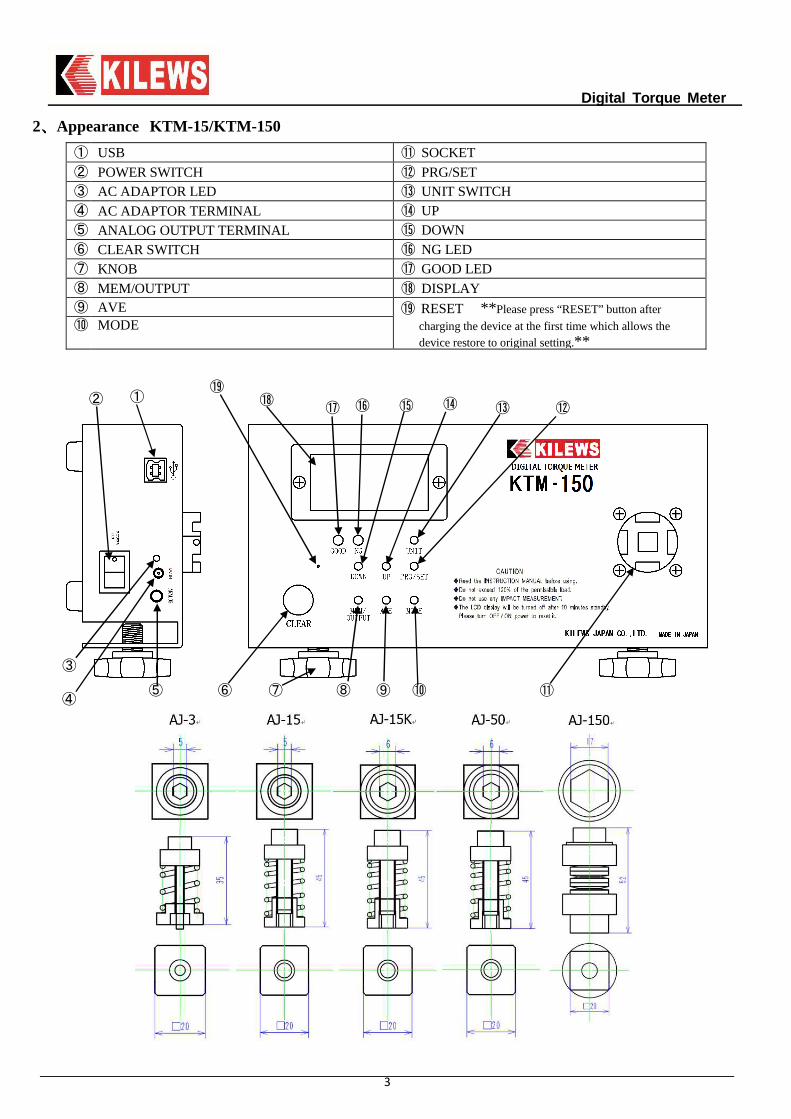
2、、、、Appearance KTM-15/KTM-150
① USB ⑪ SOCKET ② POWER SWITCH ⑫ PRG/SET ③ AC ADAPTOR LED ⑬ UNIT SWITCH ④ AC ADAPTOR TERMINAL ⑭ UP ⑤ ANALOG OUTPUT TERMINAL ⑮ DOWN ⑥ CLEAR SWITCH ⑯ NG LED ⑦ KNOB ⑰ GOOD LED ⑧ MEM/OUTPUT ⑱ DISPLAY ⑨ AVE ⑲ RESET ** Please press “RESET” button after
charging the device at the first time which allows the device restore to original setting.**
⑩ MODE
⑥ ⑦ ⑧ ⑨ ⑩ ⑪
⑫ ⑭ ⑮
⑬
⑲
⑱
⑯ ⑰
① ②
③
④
⑤
Digital Torque Meter
4
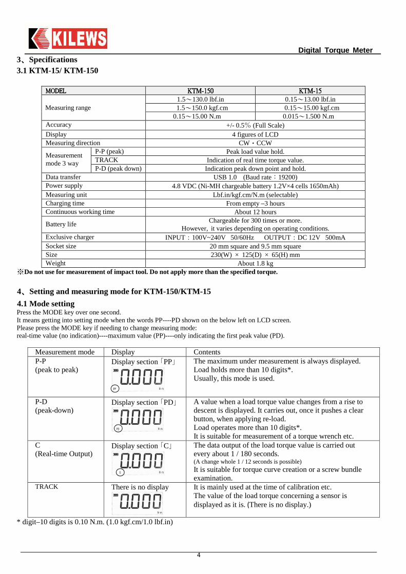
3、、、、Specifications 3.1 KTM-15/ KTM-150
MODELMODELMODELMODEL KTMKTMKTMKTM----150150150150 KTMKTMKTMKTM----11115555
Measuring range 1.5~130.0 lbf.in 0.15~13.00 lbf.in
1.5~150.0 kgf.cm 0.15~15.00 kgf.cm 0.15~15.00 N.m 0.015~1.500 N.m
Accuracy +/- 0.5% (Full Scale) Display 4 figures of LCD Measuring direction CW・CCW
Measurement mode 3 way
P-P (peak) Peak load value hold. TRACK Indication of real time torque value. P-D (peak down) Indication peak down point and hold.
Data transfer USB 1.0 (Baud rate:19200) Power supply 4.8 VDC (Ni-MH chargeable battery 1.2V×4 cells 1650mAh) Measuring unit Lbf.in/kgf.cm/N.m (selectable) Charging time From empty –3 hours Continuous working time About 12 hours
Battery life Chargeable for 300 times or more. However, it varies depending on operating conditions.
Exclusive charger INPUT:100V~240V 50/60Hz OUTPUT:DC 12V 500mA Socket size 20 mm square and 9.5 mm square Size 230(W) × 125(D) × 65(H) mm Weight About 1.8 kg
※Do not use for measurement of impact tool. Do not apply more than the specified torque.
4、、、、Setting and measuring mode for KTM-150/KTM-15
4.1 Mode setting Press the MODE key over one second. It means getting into setting mode when the words PP----PD shown on the below left on LCD screen. Please press the MODE key if needing to change measuring mode: real-time value (no indication)----maximum value (PP)----only indicating the first peak value (PD).
Measurement mode Display Contents P-P (peak to peak)
Display section 「PP」
The maximum under measurement is always displayed. Load holds more than 10 digits*. Usually, this mode is used.
P-D (peak-down)
Display section 「PD」
A value when a load torque value changes from a rise to descent is displayed. It carries out, once it pushes a clear button, when applying re-load. Load operates more than 10 digits*. It is suitable for measurement of a torque wrench etc.
C (Real-time Output)
Display section 「C」
The data output of the load torque value is carried out every about 1 / 180 seconds. (A change whole 1 / 12 seconds is possible) It is suitable for torque curve creation or a screw bundle examination.
TRACK There is no display
It is mainly used at the time of calibration etc. The value of the load torque concerning a sensor is displayed as it is. (There is no display.)
* digit–10 digits is 0.10 N.m. (1.0 kgf.cm/1.0 lbf.in)
Digital Torque Meter
5
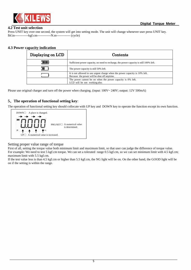
4.2 Test unit selection Press UNIT key over one second, the system will get into setting mode. The unit will change whenever user press UNIT key. lbf.in-------------kgf.cm-------------N.m------------- (cycle) 4.3 Power capacity indication
DisplayingDisplayingDisplayingDisplaying onononon LCDLCDLCDLCD ContentsContentsContentsContents
Sufficient power capacity, no need to recharge, the power capacity is still 100% left.
The power capacity is still 50% left.
It is not allowed to use urgent charge when the power capacity is 10% left. Because the power will be shut off anytime.
The power cannot be on when the power capacity is 0% left. LCD will be not working also.
Please use original charger and turn off the power when charging. (input: 100V~ 240V; output: 12V 500mA)
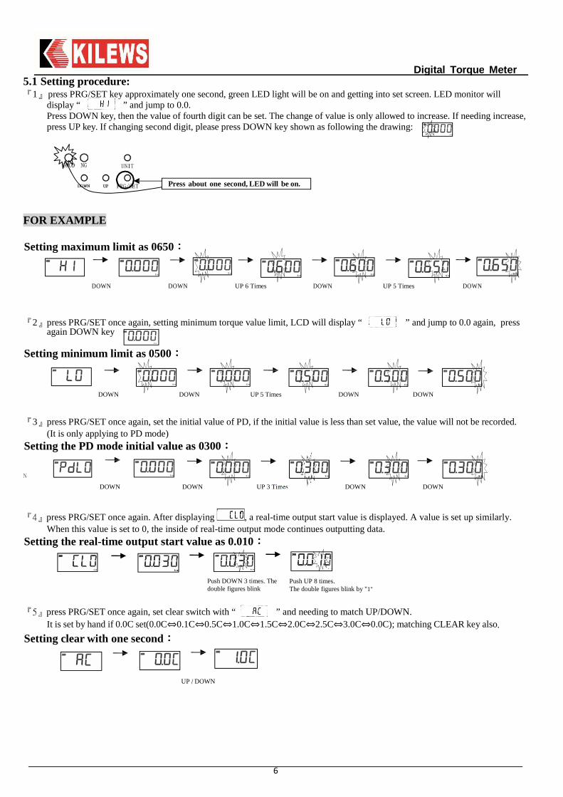
5、、、、The operation of functional setting key: The operation of functional setting key should collocate with UP key and DOWN key to operate the function except its own function.
Setting proper value range of torque First of all, setting the torque value both minimum limit and maximum limit, so that user can judge the difference of torque value. For example: We need to test 5 kgf.cm torque. We can set a tolerated range 0.5 kgf.cm, so we can set minimum limit with 4.5 kgf.cm; maximum limit with 5.5 kgf.cm. If the test value less is than 4.5 kgf.cm or higher than 5.5 kgf.cm, the NG light will be on. On the other hand, the GOOD light will be on if the setting is within the range.
UP○ A numerical value is increased.
DOWN○ A place is changed.
PRG/SET○ A numerical value is determined.
Digital Torque Meter
6
5.1 Setting procedure: 『1』 press PRG/SET key approximately one second, green LED light will be on and getting into set screen. LED monitor will
display “ ” and jump to 0.0. Press DOWN key, then the value of fourth digit can be set. The change of value is only allowed to increase. If needing increase, press UP key. If changing second digit, please press DOWN key shown as following the drawing:
FOR EXAMPLE
Setting maximum limit as 0650::::
DOWN DOWN UP 6 Times DOWN UP 5 Times DOWN
『2』press PRG/SET once again, setting minimum torque value limit, LCD will display “ ” and jump to 0.0 again, press again DOWN key
Setting minimum limit as 0500::::
DOWN DOWN UP 5 Times DOWN DOWN
『3』press PRG/SET once again, set the initial value of PD, if the initial value is less than set value, the value will not be recorded. (It is only applying to PD mode)
Setting the PD mode initial value as 0300::::
N
DOWN DOWN UP 3 Times DOWN DOWN
『4』press PRG/SET once again. After displaying , a real-time output start value is displayed. A value is set up similarly. When this value is set to 0, the inside of real-time output mode continues outputting data.
Setting the real-time output start value as 0.010::::
『5』press PRG/SET once again, set clear switch with “ ” and needing to match UP/DOWN. It is set by hand if 0.0C set(0.0C⇔0.1C⇔0.5C⇔1.0C⇔1.5C⇔2.0C⇔2.5C⇔3.0C⇔0.0C); matching CLEAR key also.
Setting clear with one second::::
UP / DOWN
Push DOWN 3 times. The double figures blink
Push UP 8 times. The double figures blink by "1"
Press about one second, LED will be on.
Digital Torque Meter
7
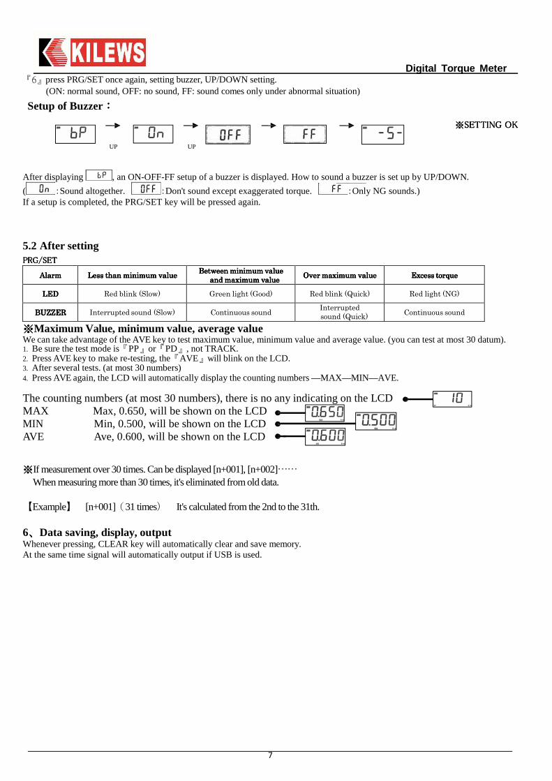
『6』press PRG/SET once again, setting buzzer, UP/DOWN setting. (ON: normal sound, OFF: no sound, FF: sound comes only under abnormal situation)
Setup of Buzzer::::
※※※※SSSSETTING OKETTING OKETTING OKETTING OK
UP UP
After displaying , an ON-OFF-FF setup of a buzzer is displayed. How to sound a buzzer is set up by UP/DOWN.
( :Sound altogether. :Don't sound except exaggerated torque. :Only NG sounds.) If a setup is completed, the PRG/SET key will be pressed again.
5.2 After setting PRG/SETPRG/SETPRG/SETPRG/SET
AlarmAlarmAlarmAlarm LessLessLessLess thanthanthanthan minimumminimumminimumminimum valuevaluevaluevalue BetweenBetweenBetweenBetween minimumminimumminimumminimum valuevaluevaluevalue
andandandand maximummaximummaximummaximum valuevaluevaluevalue OverOverOverOver maximummaximummaximummaximum valuevaluevaluevalue ExcessExcessExcessExcess torquetorquetorquetorque
LEDLEDLEDLED Red blink (Slow) Green light (Good) Red blink (Quick) Red light (NG)
BUZZERBUZZERBUZZERBUZZER Interrupted sound (Slow) Continuous sound Interrupted sound (Quick)
Continuous sound
※※※※Maximum Value, minimum value, average value We can take advantage of the AVE key to test maximum value, minimum value and average value. (you can test at most 30 datum). 1. Be sure the test mode is『PP』or『PD』, not TRACK. 2. Press AVE key to make re-testing, the『AVE』will blink on the LCD. 3. After several tests. (at most 30 numbers) 4. Press AVE again, the LCD will automatically display the counting numbers —MAX—MIN—AVE.
The counting numbers (at most 30 numbers), there is no any indicating on the LCD MAX Max, 0.650, will be shown on the LCD MIN Min, 0.500, will be shown on the LCD AVE Ave, 0.600, will be shown on the LCD
※※※※If measurement over 30 times. Can be displayed [n+001], [n+002]……
When measuring more than 30 times, it's eliminated from old data. 【Example】 [n+001](31 times) It's calculated from the 2nd to the 31th. 6、、、、Data saving, display, output Whenever pressing, CLEAR key will automatically clear and save memory. At the same time signal will automatically output if USB is used.
Digital Torque Meter
8
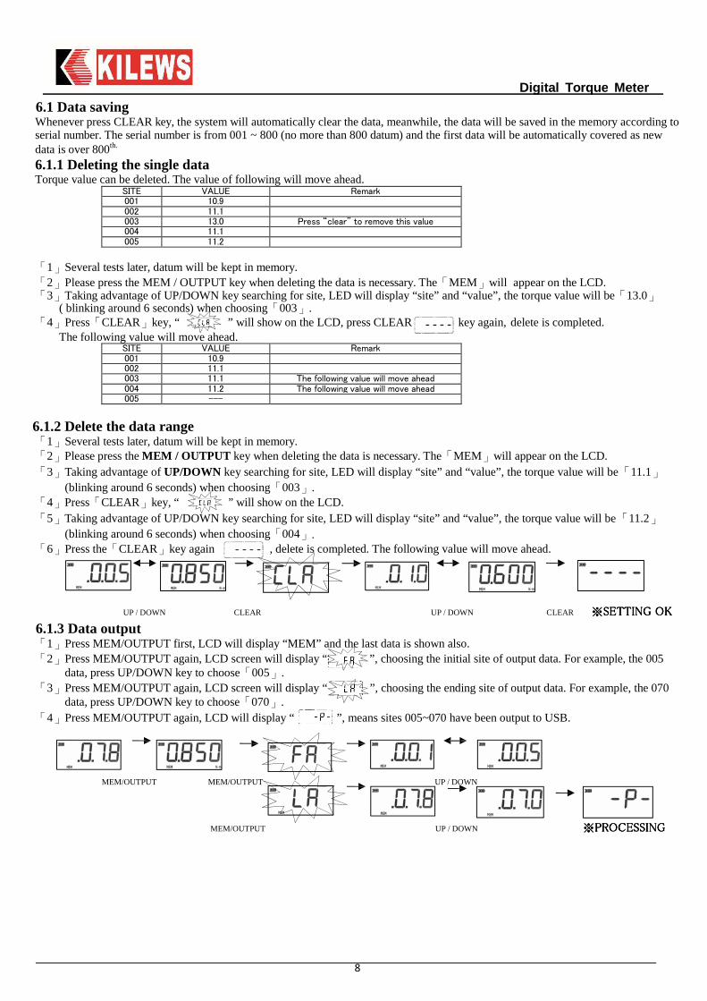
6.1 Data saving Whenever press CLEAR key, the system will automatically clear the data, meanwhile, the data will be saved in the memory according to serial number. The serial number is from 001 ~ 800 (no more than 800 datum) and the first data will be automatically covered as new data is over 800th.
6.1.1 Deleting the single data Torque value can be deleted. The value of following will move ahead.
SITE VALUE Remark
001 10.9 002 11.1 003 13.0 Press “clear” to remove this value
004 11.1 005 11.2
「1」Several tests later, datum will be kept in memory. 「2」Please press the MEM / OUTPUT key when deleting the data is necessary. The「MEM」will appear on the LCD. 「3」Taking advantage of UP/DOWN key searching for site, LED will display “site” and “value”, the torque value will be「13.0」
( blinking around 6 seconds) when choosing「003」. 「4」Press「CLEAR」key, “ ” will show on the LCD, press CLEAR key again, delete is completed.
The following value will move ahead. SITE VALUE Remark
001 10.9 002 11.1 003 11.1 The following value will move ahead
004 11.2 The following value will move ahead
005 ---
6.1.2 Delete the data range 「1」Several tests later, datum will be kept in memory. 「2」Please press the MEM / OUTPUT key when deleting the data is necessary. The「MEM」will appear on the LCD. 「3」Taking advantage of UP/DOWN key searching for site, LED will display “site” and “value”, the torque value will be「11.1」
(blinking around 6 seconds) when choosing「003」. 「4」Press「CLEAR」key, “ ” will show on the LCD. 「5」Taking advantage of UP/DOWN key searching for site, LED will display “site” and “value”, the torque value will be「11.2」
(blinking around 6 seconds) when choosing「004」. 「6」Press the「CLEAR」key again , delete is completed. The following value will move ahead.
UP / DOWN CLEAR UP / DOWN CLEAR ※※※※SSSSETTETTETTETTINGINGINGING OKOKOKOK
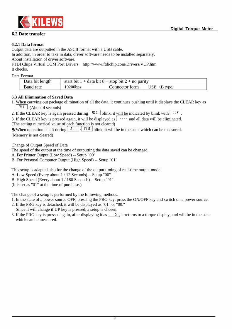
6.1.3 Data output 「1」Press MEM/OUTPUT first, LCD will display “MEM” and the last data is shown also. 「2」Press MEM/OUTPUT again, LCD screen will display “ ”, choosing the initial site of output data. For example, the 005
data, press UP/DOWN key to choose「005」. 「3」Press MEM/OUTPUT again, LCD screen will display “ ”, choosing the ending site of output data. For example, the 070
data, press UP/DOWN key to choose「070」. 「4」Press MEM/OUTPUT again, LCD will display “ ”, means sites 005~070 have been output to USB.
MEM/OUTPUT MEM/OUTPUT UP / DOWN
MEM/OUTPUT UP / DOWN ※※※※PROCESSINGPROCESSINGPROCESSINGPROCESSING
Digital Torque Meter
9
6.2 Date transfer 6.2.1 Data format Output data are outputted in the ASCII format with a USB cable. In addition, in order to take in data, driver software needs to be installed separately. About installation of driver software. FTDI Chips Virtual COM Port Drivers http://www.ftdichip.com/Drivers/VCP.htm It checks.
Data Format Data bit length start bit 1 + data bit 8 + stop bit 2 + no parity Baud rate 19200bps Connector form USB(B type)
6.3 All Elimination of Saved Data 1. When carrying out package elimination of all the data, it continues pushing until it displays the CLEAR key as
. (About 4 seconds) 2. If the CLEAR key is again pressed during blink, it will be indicated by blink with . 3. If the CLEAR key is pressed again, it will be displayed as and all data will be eliminated. (The setting numerical value of each function is not cleared) ※※※※When operation is left during ・ blink, it will be in the state which can be measured. (Memory is not cleared)
Change of Output Speed of Data The speed of the output at the time of outputting the data saved can be changed. A. For Printer Output (Low Speed) -- Setup "00" B. For Personal Computer Output (High Speed) -- Setup "01" This setup is adapted also for the change of the output timing of real-time output mode. A. Low Speed (Every about 1 / 12 Seconds) -- Setup "00" B. High Speed (Every about 1 / 180 Seconds) -- Setup "01" (It is set as "01" at the time of purchase.) The change of a setup is performed by the following methods. 1. In the state of a power source OFF, pressing the PRG key, press the ON/OFF key and switch on a power source. 2. If the PRG key is detached, it will be displayed as "01" or "00."
Since it will change if UP key is pressed, a setup is chosen. 3. If the PRG key is pressed again, after displaying it as , it returns to a torque display, and will be in the state
which can be measured.
Digital Torque Meter
10
7、、、、Preparation and the measuring method Installation A measuring instrument may be brandished at the time of measurement of a large torque. Surely, a measuring instrument should use a fixed knob etc. and fix it firmly.
A setup in the measurement mode The 3 following modes can be chosen with the setting. (It unites with the use purpose and please choose.)
PP (peak measurement): The maximum under measurement is always displayed. TRACK (track measurement): The value of the load torque concerning the detection machine is displayed as it is. PD (peak down measurement) : Value when load torque value changes from a rise to descent is displayed. Carry out after pushing a CLEAR button at once when applying re-load. ※※※※PD and PP measurement operates from 10 or more numerical values.
Measuring method
Check that the display part is zero at the time of power supply ON. If display is not show as zero, set a measurement mode select switch to TRACK, push CLEAR button, and set it as back PP which performed zero adjustment. The bit of screwdriver to measure among the screw part of screw joint is set firmly, and screwdriver is started. It checks that operation of screwdriver has been completed normally, the measurement torque value of a display part is read, and it becomes a measurement end. After a measurement end, if CLEAR button is pushed, a display will be cleared by zero. When continuing measurement, it repeats from (1) again. Choose the TRACK mode, if real time torque value want to be measured.
8、、、、Power supply If this measuring instrument is left 10 minutes or more or battery capacity stops being sufficient, a power supply is turned off automatically. If battery capacity decreases, since LOBAT will be displayed, charge by inserting the connector of an exclusive charger in an AC ADAPTOR terminal. The fully charge is in the state which turned OFF the power supply switch, and takes about 8 hours. (Do not perform charge of 8 hours or more. It may become the cause of the fire by a burst of a battery, generation of heat, and liquid leak, or an injury by fault charge.) Moreover, when turning off a power supply, a power supply SW is pushed for about 1 second.
9、、、、System Reset CPU in the tester might not start even if the battery charges it with electricity complete discharged. (When not using it for a long time.) In that case, an AC/DC adaptor is connected and a system reset button is pushed. It will be in an initial state (all the contents of memory are eliminated). Do not use it under the following condition. ※※※※When the display doesn't appear even if this machine is not used for a long time and charged. ※※※※Additionally, when the tester doesn't work. Since all the contents of memory are eliminated when system reset is performed, redo a setup once again.
10、、、、Guarantee
It is allowed to fix gratuitously, if the fault which will originate in manufacture, transportation, etc. of our company within one year after a purchase should occur, although product was manufactured under sufficient quality control. In the following case, it becomes the charge also within a guarantee term. Failure by the error, and unjust repair and unjust reconstruction and damage on use Failure by fall etc. and damage after a purchase. Failure by the natural disaster, pollution, and unusual voltage, and damage.
Digital Torque Meter
11
11、、、、Calibration trust service Periodical calibration is required in order to manage the accuracy of torque meter. By our company, the calibration with the high reliability traced to the national standard is performed, and in order to use it within accuracy, I recommend you calibration of one year. I offer a result of calibration document, a certification on calibration, and a traceability system figure by demand. (Periodical calibration is a charge.) Documents appended at the time of product purchase. Result of calibration document. Certification on calibration document. Traceability system figure.
The cautions on use ※※※※Please do not apply the load more than the measurement range by any means. ※※※※Attached grease is attached to the bolt or the bearing part, please check before use. ※※※※Where a spring is loosened, please be sure to keep after use. The number of times of an exchange standard is about 2500 times. When the following condition comes out, please stop using, and change to new joint. When there is bend and wear of a screw thread. When there is sound etc.
The new model KTM-15/KTM-150 itself has temporary memory. The memory will be cleared automatically once the machine is not used for a long time. Moreover it is necessary to press “Reset” button after full-charged, then it can be on normally. The user should pay attention to the battery status or save data periodically for keeping memory from losing.
12、、、、Electric Screwdriver & Torque Meter 1、、、、Torque adjustment for Electric Screwdriver A.Turn the Torque Adjusting Ring to increase or decrease the torque output. Adjust clockwise to higher scale means
torque increase; anti-clockwise to lower scale means torque decrease. B.Operate electric screwdriver should be step by step in proper sequence, first run with a small torque to fasten the
screw, if feel not enough torque, then adjust to higher torque gradually. C.The mutual relation between torque output and scale, please refer to the “Torque Range Chart” on the instruction.
The correct torque adjustment of fastening screws in subject to screws type, material, size and the object material of being screwed.
D.When object has been done screw-fastening, see if it meets the standard of quality, then measure the right torque value by Torque Meter, if the screw fastening situation is not yet to reach standard, adjust the torque from electric screwdriver until meets the standard.
E.Record the torque value with Torque Meter for electric screwdriver, and turn open the front clamping ring of electric screwdriver’s housing, then exchange Torque Fixing Ring to prevent from exceptional torque change.
※CAUTION※

Digital Torque Meter
12
For any inquiry, please contact your dealer!
KILEWS WEST USA INC. 6945 LTC PKWYPORT ST LUCIE, FL 34986 USAPH. +1(772)293-0071 FX. +1(772)465-4368EMAIL. [email protected]. WWW.KILEWSWEST.COM
2、、、、Torque Meter Operating Method (Tools: Torque Meter, Automatic Electric Screwdriver) A.Choose a proper electric screwdriver type in accordance with the required torque of screw-fastening. Please consult
with electric screwdriver catalogue or vector chart of electric screwdriver B.Choose a proper Torque Meter: KTM-15 can be measured torque at maximum 15 kgf.cm ; KTM-150 can be measured
torque at maximum 150 kgf.cm; KTM-250 can be measured torque at maximum 250 kgf.cm select the Screw Joint (According to the basis of requiring torque measurement which can be parted with 6 items as following tables:
Torque Range (kgf.cm) Torque Meter Spring Joint Remark
Under 3.0 KTM-15 AJ-3 Max measurable
3 kgf.cm
3.0~15.0 KTM-15 AJ-15 Max measurable
15 kgf.cm KTM-150 AJ-15K
10.0~50.0 KTM-150 AJ-50 Max measurable
50 kgf.cm
50~150 KTM-150 AJ-150 Max measurable
150 kgf.cm
50~250 KTM-250 AJ-250 Max measurable
250 kgf.cm
C.Test procedures: 1.Switch on the power2.Set Measure Mode (MODE) to “TRACK” 3.Unit Switch sets to required measurement of unit. (lbf.in;kgf.cm;N.m)
D.Reset adjustment: Check the value on LED display if is at zero status, if not then press Reset button (CLEAR) to display 0.0.
E.Set Measure Mode (MODE) to “PEAK”. F.Cover with connecting pole of Screw Joint on the electric screwdriver, put another end of connecting pole in the head
terminal of Screw Joint, power on the electric screwdriver and start to measure output torque of the electric screwdriver.
G.When torque value has been indicated, it means functional measurement for electric screwdriver is normal and accomplished; the value indicates on LED display is the output torque value of electric screwdriver.
H.After finishing the measurement of electric screwdriver, reverse to loose Screw Joint for keeping from springiness fatigue.
I . Use the same electric screwdriver on different brands of Torque Meters (or Screw Joint) could result in different torque value inaccuracy, such inaccuracy comes mostly from different spring character of Screw Joint. If there are two sets or more Torque Meters using on the work site, responsible department should examine Torque Meters periodically and check the gap of spring character among those Screw Joint whether too large, if the answer is yes, then need to change a new spring or the whole set of Screw Joint.
J.Please note while using Torque Meter, don’t charge the battery at the same time in order to avoid affecting the accuracy of test data.