Embed Size (px)
Citation preview
i
KT6 Delta
Version 2.0G52-M6590X9-K01
MS-6590 (v2.X) ATX Mainboard

ii
Manual Rev: 2.0Release Date: July 2003
FCC-B Radio Frequency Interference Statement
This equipment has been tested and found to comply with the limits for a classB digital device, pursuant to part 15 of the FCC rules. These limits are designedto provide reasonable protection against harmful interference when the equip-ment is operated in a commercial environment. This equipment generates, usesand can radiate radio frequency energy and, if not installed and used in accor-dance with the instruction manual, may cause harmful interference to radiocommunications. Operation of this equipment in a residential area is likely tocause harmful interference, in which case the user will be required to correctthe interference at his own expense.
Notice 1The changes or modifications not expressly approved by the party respon-sible for compliance could void the user’s authority to operate the equipment.
Notice 2Shielded interface cables and A.C. power cord, if any, must be used in order tocomply with the emission limits.
VOIR LA NOTICE D’INSTALLATION AVANT DE RACCORDER AURESEAU.
Micro-Star International MS-6590
Tested to comply with FCC Standard
For Home or Office Use
iii
Copyright Notice
The material in this document is the intellectual property of MICRO-STARINTERNATIONAL. We take every care in the preparation of this document,but no guarantee is given as to the correctness of its contents. Our productsare under continual improvement and we reserve the right to make changeswithout notice.
Trademarks
All trademarks are the properties of their respective owners.
AMD, Athlon™, Athlon™ XP, Thoroughbred™, and Duron™ are registeredtrademarks of AMD Corporation.Intel® and Pentium® are registered trademarks of Intel Corporation.PS/2 and OS®/2 are registered trademarks of International Business MachinesCorporation.Microsoft is a registered trademark of Microsoft Corporation. Windows® 98/2000/NT/XP are registered trademarks of Microsoft Corporation.NVIDIA, the NVIDIA logo, DualNet, and nForce are registered trademarks ortrademarks of NVIDIA Corporation in the United States and/or other countries.Netware® is a registered trademark of Novell, Inc.Award® is a registered trademark of Phoenix Technologies Ltd.AMI® is a registered trademark of American Megatrends Inc.Kensington and MicroSaver are registered trademarks of the Kensington Tech-nology Group.PCMCIA and CardBus are registered trademarks of the Personal ComputerMemory Card International Association.
Revision HistoryRevision Revision History DateV2.0 First release with chipset July 2003
VIA KT600 & VIA VT8237

iv
1. Always read the safety instructions carefully.2. Keep this User’s Manual for future reference.3. Keep this equipment away from humidity.4. Lay this equipment on a reliable flat surface before setting it up.5. The openings on the enclosure are for air convection hence protects the
equipment from overheating. Do not cover the openings.6. Make sure the voltage of the power source and adjust properly 110/220V
before connecting the equipment to the power inlet.7. Place the power cord such a way that people can not step on it. Do not
place anything over the power cord.8. Always Unplug the Power Cord before inserting any add-on card or module.9. All cautions and warnings on the equipment should be noted.10. Never pour any liquid into the opening that could damage or cause electrical
shock.11. If any of the following situations arises, get the equipment checked by a
service personnel:The power cord or plug is damaged.Liquid has penetrated into the equipment.The equipment has been exposed to moisture.The equipment has not work well or you can not get it work accordingto User’s Manual.The equipment has dropped and damaged.The equipment has obvious sign of breakage.
12. Do not leave this equipment in an environment unconditioned, storagetemperature above 600 C (1400F), it may damage the equipment.
Safety Instructions
CAUTION: Danger of explosion if battery is incorrectly replaced.Replace only with the same or equivalent type recommended by themanufacturer.
v
CONTENTSFCC-B Radio Frequency Interference Statement ........................................... iiCopyright Notice .......................................................................................... iiiRevision History ........................................................................................... iiiTechnical Support ......................................................................................... iiiSafety Instructions ....................................................................................... ivChapter 1. Getting Started ........................................................................ 1-1
Mainboard Specifications .................................................................... 1-2Mainboard Layout ............................................................................... 1-4MSI Special Features ........................................................................... 1-5
Super Pack (Optional) .................................................................... 1-5Core Center .................................................................................... 1-6Core Cell™ Chip ............................................................................ 1-8Live BIOS™ / Live Driver™ .......................................................... 1-9D-Bracket™ 2 (Optional) ............................................................. 1-10Color Management ...................................................................... 1-12Round Cable (Optional) ............................................................... 1-13S-Bracket (Optional) .................................................................... 1-14
Chapter 2. Hardware Setup ....................................................................... 2-1Quick Components Guide .................................................................... 2-2Central Processing Unit: CPU .............................................................. 2-3
CPU Core Speed Derivation Procedure ......................................... 2-3CPU Installation Procedures for Socket 462 .................................. 2-4Installing AMD Athlon CPU (Socket 462) Cooler Set ................... 2-5
Memory ................................................................................................ 2-6Introduction to DDR SDRAM ....................................................... 2-6DDR DIMM Module Combination ................................................ 2-7Installing DDR Modules ............................................................... 2-7
Power Supply ....................................................................................... 2-8ATX 20-Pin Power Connector: JWR1 ............................................ 2-8ATX 12V Power Connector: JPW1 ................................................ 2-8
vi
Back Panel ............................................................................................ 2-9Mouse Connector ......................................................................... 2-9Keyboard Connector ................................................................... 2-10USB 2.0 Connectors .................................................................... 2-10Serial Port Connectors: COM A & COM B.................................. 2-11RJ-45 LAN Jack (Optional) .......................................................... 2-11Parallel Port Connector: LPT1 ...................................................... 2-12Audio Port Connectors ............................................................... 2-13
Connectors ......................................................................................... 2-14Floppy Disk Drive Connector: FDD1........................................... 2-14Fan Power Connectors: CFAN1/SFAN1/NBFAN1 ...................... 2-15Hard Disk Connectors: IDE1 & IDE2 ........................................... 2-16Serial ATA/Serial ATA RAID Connectors controlled by VT8237: SATA1 & SATA2 .............................................. 2-17Hard Disk RAID Connectors controlled by Promise 20378: IDE3, SER1 & SER2 (Optional) .................................. 2-18CD-In Connector: J3 .................................................................... 2-20S-Bracket (SPDIF) Connector: JSP3 (Optional) ............................ 2-20IEEE 1394 Connectors: J1394_0, J1394_1, J1394_2 (Optional) ..... 2-22Front Panel Connectors: JFP1 & JFP2 ......................................... 2-24Front Panel Audio Connector: JAUD1 ........................................ 2-25Front USB Connectors: JUSB1 .................................................... 2-26D-Bracket™ 2 Connector: JLED1 (Optional) ............................... 2-27Chassis Intrusion Switch Connector: J6 ...................................... 2-28IrDA Infrared Module Header: JIR1 ............................................ 2-28
Jumpers .............................................................................................. 2-29Clear CMOS Jumper: JBAT1 ........................................................ 2-29Center/Subwoofer Speaker Setting Jumper: JS1 .......................... 2-30
Slots ................................................................................................... 2-31AGP (Accelerated Graphics Port) Slot ......................................... 2-31PCI (Peripheral Component Interconnect) Slots .......................... 2-31
vii
PCI Interrupt Request Routing .................................................... 2-32Chapter 3. BIOS Setup .............................................................................. 3-1
Entering Setup ...................................................................................... 3-2Selecting the First Boot Device ..................................................... 3-2Control Keys ................................................................................. 3-3Getting Help .................................................................................. 3-3
The Main Menu ................................................................................... 3-4Standard CMOS Features .................................................................... 3-6Advanced BIOS Features .................................................................... 3-8Advanced Chipset Features ............................................................... 3-13Power Management Features ............................................................. 3-17PNP/PCI Configurations ..................................................................... 3-21Integrated Peripherals ........................................................................ 3-23PC Health Status ................................................................................ 3-26Frequency/Voltage Control ................................................................ 3-27Set Supervisor/User Password ........................................................... 3-29Load High Performance/BIOS Setup Defaults .................................... 3-30
Appendix A. Using 4- or 6-Channel Audio Function .................................A-1Installing C-Media Drivers ..................................................................A-2Hardware Configuration ......................................................................A-4Software Configuration .......................................................................A-5Using 4- or 6-Channel Audio Function ............................................. A-19
Appendix B. VIA VT8237 Serial ATA RAID Introduction .......................B-1Introduction ........................................................................................ B-2BIOS Configuration ............................................................................. B-4Installing RAID Software & Drivers .................................................. B-14Using VIA RAID Tool ....................................................................... B-17
1-1
Getting Started
Chapter 1. Gett ingStarted
Thank you for purchasing KT6 Delta (MS-6590 v2.X)ATX mainboard. The KT6 Delta is based on VIA® Apollo KT600& VT8237 chipsets and provides eight USB 2.0 ports for high-speed data transmission, C-Media 9739A chip for 6-channel audiooutput and one SPDIF pinheader for digital audio transmission.Designed to fit the advanced AMD® Athlon™, Athlon™ XP orDuron™ processors, the KT6 Delta delivers a high performanceand professional desktop platform solution.
Getting Started
1-2
MS-6590 ATX Mainboard
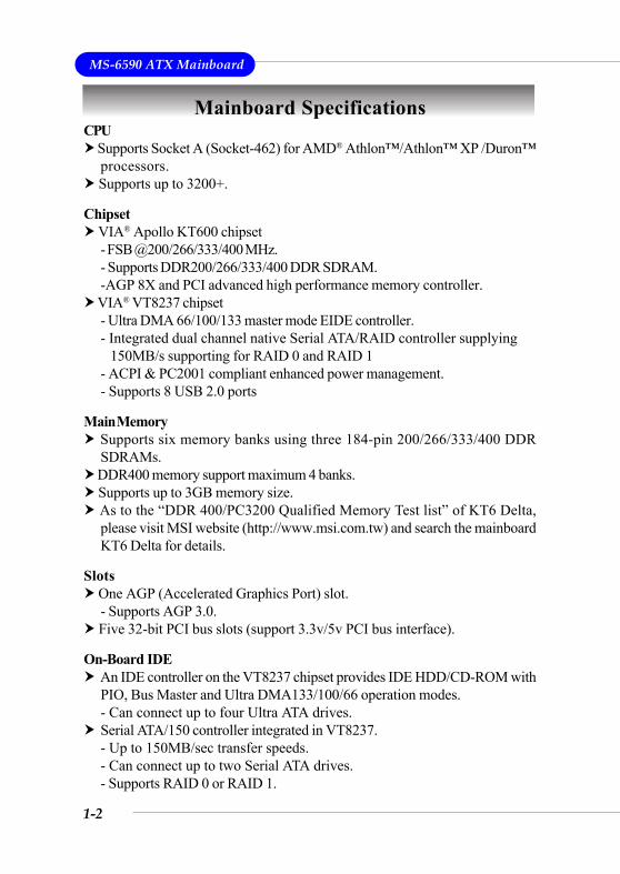
Mainboard SpecificationsCPU
Supports Socket A (Socket-462) for AMD® Athlon™/Athlon™ XP /Duron™processors.
Supports up to 3200+.
Chipset VIA® Apollo KT600 chipset- FSB @200/266/333/400 MHz.- Supports DDR200/266/333/400 DDR SDRAM.-AGP 8X and PCI advanced high performance memory controller.
VIA® VT8237 chipset- Ultra DMA 66/100/133 master mode EIDE controller.- Integrated dual channel native Serial ATA/RAID controller supplying 150MB/s supporting for RAID 0 and RAID 1- ACPI & PC2001 compliant enhanced power management.- Supports 8 USB 2.0 ports
Main Memory Supports six memory banks using three 184-pin 200/266/333/400 DDRSDRAMs.
DDR400 memory support maximum 4 banks. Supports up to 3GB memory size. As to the “DDR 400/PC3200 Qualified Memory Test list” of KT6 Delta,please visit MSI website (http://www.msi.com.tw) and search the mainboardKT6 Delta for details.
Slots One AGP (Accelerated Graphics Port) slot.- Supports AGP 3.0.
Five 32-bit PCI bus slots (support 3.3v/5v PCI bus interface).
On-Board IDE An IDE controller on the VT8237 chipset provides IDE HDD/CD-ROM withPIO, Bus Master and Ultra DMA133/100/66 operation modes.- Can connect up to four Ultra ATA drives.Serial ATA/150 controller integrated in VT8237.- Up to 150MB/sec transfer speeds.- Can connect up to two Serial ATA drives.- Supports RAID 0 or RAID 1.
1-3
Getting Started
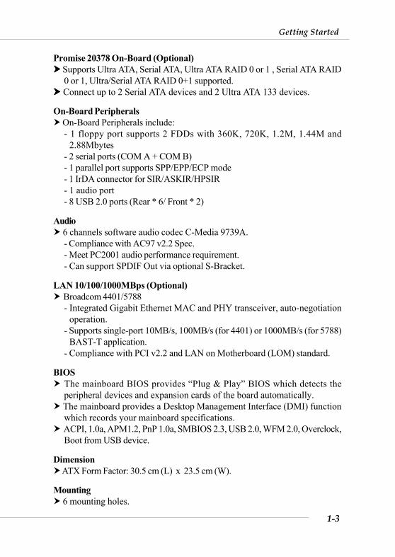
Promise 20378 On-Board (Optional) Supports Ultra ATA, Serial ATA, Ultra ATA RAID 0 or 1 , Serial ATA RAID0 or 1, Ultra/Serial ATA RAID 0+1 supported.
Connect up to 2 Serial ATA devices and 2 Ultra ATA 133 devices.
On-Board Peripherals On-Board Peripherals include:- 1 floppy port supports 2 FDDs with 360K, 720K, 1.2M, 1.44M and
2.88Mbytes- 2 serial ports (COM A + COM B)- 1 parallel port supports SPP/EPP/ECP mode- 1 IrDA connector for SIR/ASKIR/HPSIR- 1 audio port- 8 USB 2.0 ports (Rear * 6/ Front * 2)
Audio 6 channels software audio codec C-Media 9739A.- Compliance with AC97 v2.2 Spec.- Meet PC2001 audio performance requirement.- Can support SPDIF Out via optional S-Bracket.
LAN 10/100/1000MBps (Optional) Broadcom 4401/5788- Integrated Gigabit Ethernet MAC and PHY transceiver, auto-negotiation
operation.- Supports single-port 10MB/s, 100MB/s (for 4401) or 1000MB/s (for 5788)
BAST-T application.- Compliance with PCI v2.2 and LAN on Motherboard (LOM) standard.
BIOS The mainboard BIOS provides “Plug & Play” BIOS which detects theperipheral devices and expansion cards of the board automatically.
The mainboard provides a Desktop Management Interface (DMI) functionwhich records your mainboard specifications.
ACPI, 1.0a, APM1.2, PnP 1.0a, SMBIOS 2.3, USB 2.0, WFM 2.0, Overclock,Boot from USB device.
Dimension ATX Form Factor: 30.5 cm (L) x 23.5 cm (W).
Mounting 6 mounting holes.
1-4
MS-6590 ATX Mainboard
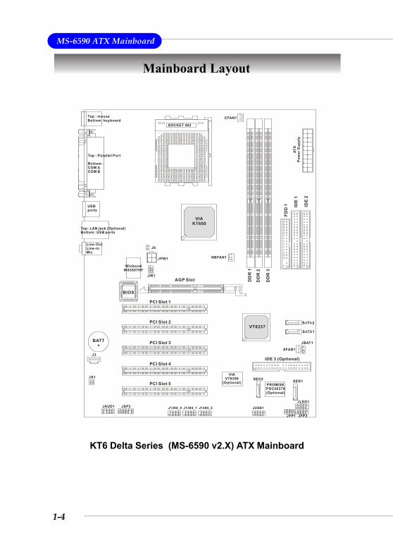
Mainboard Layout
KT6 Delta Series (MS-6590 v2.X) ATX Mainboard
BATT+
VT8237
VIAKT600
DD
R 1
DD
R 2
DD
R 3
ATX
Pow
er S
uppl
y
JAUD1
J3
SOCKET 462
BIOS
PCI Slot 5
PCI Slot 4
PCI Slot 3
PCI Slot 2
PCI Slot 1ID
E 1
IDE 3 (Optional)
IDE
2
JBAT1
JLED1
JFP1 JFP2
JSP3
SER1
USBports
Top: LAN jack (Optional)Bottom: USB ports
Top : Parallel Port
Bottom: COM ACOM B
Top : mouse Bottom: keyboard
CFAN1
NBFAN1
SFAN1
WinbondW83697HF
PROMISEPDC20378(Optional)
Line-OutLine-InMic
FDD
1AGP Slot
J1394_0
VIAVT6306
(Optional)
JIR1
J6
J1394_1 J1394_2 JUSB1
JS1
JPW1
1-5
Getting Started
MSI Special Features
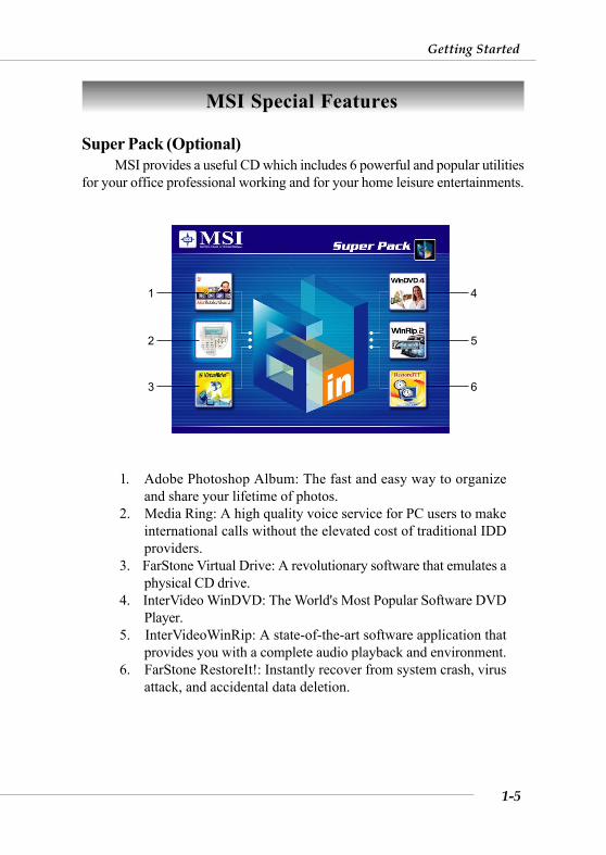
Super Pack (Optional)MSI provides a useful CD which includes 6 powerful and popular utilities
for your office professional working and for your home leisure entertainments.
1. Adobe Photoshop Album: The fast and easy way to organizeand share your lifetime of photos.
2. Media Ring: A high quality voice service for PC users to makeinternational calls without the elevated cost of traditional IDDproviders.
3. FarStone Virtual Drive: A revolutionary software that emulates aphysical CD drive.
4. InterVideo WinDVD: The World's Most Popular Software DVDPlayer.
5. InterVideoWinRip: A state-of-the-art software application thatprovides you with a complete audio playback and environment.
6. FarStone RestoreIt!: Instantly recover from system crash, virusattack, and accidental data deletion.
1
2
3
4
5
6
1-6
MS-6590 ATX Mainboard
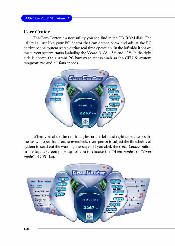
Core CenterThe Core Center is a new utility you can find in the CD-ROM disk. The
utility is just like your PC doctor that can detect, view and adjust the PChardware and system status during real time operation. In the left side it showsthe current system status including the Vcore, 3.3V, +5V and 12V. In the rightside it shows the current PC hardware status such as the CPU & systemtemperatures and all fans speeds.
When you click the red triangles in the left and right sides, two sub-menus will open for users to overclock, overspec or to adjust the thresholds ofsystem to send out the warning messages. If you click the Core Center buttonin the top, a screen pops up for you to choose the “Auto mode” or “Usermode” of CPU fan.
1-7
Getting Started
Left-side: Current system statusIn the left sub-menu, you can configure the settings of FSB, Vcore,
Memory Voltage and AGP Voltage by clicking the radio button in front of eachitem and make it available (the radio button will be lit as yellow when selected),use the “+” and “-” buttons to adjust, then click “OK” to apply the changes.Then you can click Save to save the desired FSB you just configured.
Also you may click Auto to start testing the maximal CPU overclockingvalue, The CPU FSB will automatically increase the testing value until the PCreboots. Or you may click Default to restore the default values.
Right-side: PC hardware status during real time operationIn the right sub-menu, here you can configure the PC hardware status
such as CPU & system temperatures and fan speeds. You may use the scrollbars to adjust each item, then click “OK” to apply the changes. The values youset for the temperatures are the maximum thresholds for the system for warnings,and the value for fan speeds are the minimum thresholds.
Top-side: User mode/Auto modeHere you may adjust the CPU fan speed. If you choose User mode, you
may adjust the CPU fan speed in 8 different modes, from Stop to Full speed.
1-8
MS-6590 ATX Mainboard
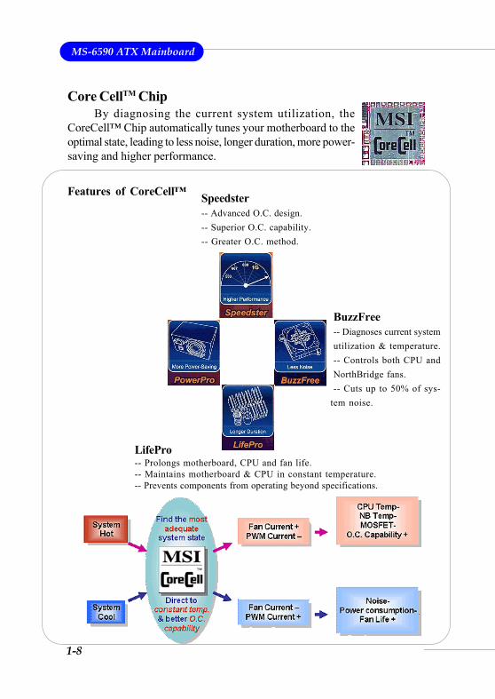
BuzzFree-- Diagnoses current systemutilization & temperature.-- Controls both CPU andNorthBridge fans.-- Cuts up to 50% of sys-
tem noise.
LifePro-- Prolongs motherboard, CPU and fan life.-- Maintains motherboard & CPU in constant temperature.-- Prevents components from operating beyond specifications.
Speedster-- Advanced O.C. design.-- Superior O.C. capability.-- Greater O.C. method.
Features of CoreCell™
Core CellTM ChipBy diagnosing the current system utilization, the
CoreCell™ Chip automatically tunes your motherboard to theoptimal state, leading to less noise, longer duration, more power-saving and higher performance.
1-9
Getting Started
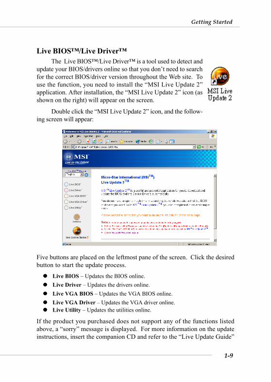
Live BIOS™/Live Driver™The Live BIOS™/Live Driver™ is a tool used to detect and
update your BIOS/drivers online so that you don’t need to searchfor the correct BIOS/driver version throughout the Web site. Touse the function, you need to install the “MSI Live Update 2”application. After installation, the “MSI Live Update 2” icon (asshown on the right) will appear on the screen.
Double click the “MSI Live Update 2” icon, and the follow-ing screen will appear:
Five buttons are placed on the leftmost pane of the screen. Click the desiredbutton to start the update process.
Live BIOS – Updates the BIOS online.Live Driver – Updates the drivers online.Live VGA BIOS – Updates the VGA BIOS online.Live VGA Driver – Updates the VGA driver online.Live Utility – Updates the utilities online.
If the product you purchased does not support any of the functions listedabove, a “sorry” message is displayed. For more information on the updateinstructions, insert the companion CD and refer to the “Live Update Guide”
1-10
MS-6590 ATX Mainboard
D-BracketTM2 Description
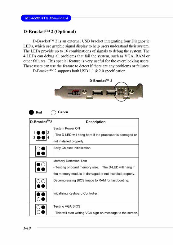
System Power ON
- The D-LED will hang here if the processor is damaged or
not installed properly.
Early Chipset Initialization
Memory Detection Test
- Testing onboard memory size. The D-LED will hang if
the memory module is damaged or not installed properly.
Decompressing BIOS image to RAM for fast booting.
Initializing Keyboard Controller.
Testing VGA BIOS
- This will start writing VGA sign-on message to the screen.
1 23 4
Red Green
D-Bracket™ 2
1 23 4
D-Bracket™ 2 (Optional)
D-Bracket™ 2 is an external USB bracket integrating four DiagnosticLEDs, which use graphic signal display to help users understand their system.The LEDs provide up to 16 combinations of signals to debug the system. The4 LEDs can debug all problems that fail the system, such as VGA, RAM orother failures. This special feature is very useful for the overclocking users.These users can use the feature to detect if there are any problems or failures.
D-Bracket™ 2 supports both USB 1.1 & 2.0 specification.
1-11
Getting Started
D-BracketTM2 Description
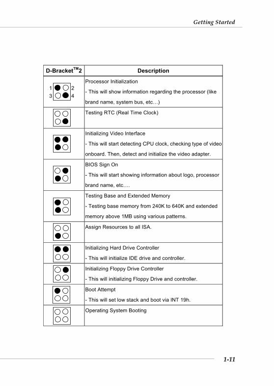
Processor Initialization
- This will show information regarding the processor (like
brand name, system bus, etc…)
Testing RTC (Real Time Clock)
Initializing Video Interface
- This will start detecting CPU clock, checking type of video
onboard. Then, detect and initialize the video adapter.
BIOS Sign On
- This will start showing information about logo, processor
brand name, etc….
Testing Base and Extended Memory
- Testing base memory from 240K to 640K and extended
memory above 1MB using various patterns.
Assign Resources to all ISA.
Initializing Hard Drive Controller
- This will initialize IDE drive and controller.
Initializing Floppy Drive Controller
- This will initializing Floppy Drive and controller.
Boot Attempt
- This will set low stack and boot via INT 19h.
Operating System Booting
1 23 4
1-12
MS-6590 ATX Mainboard
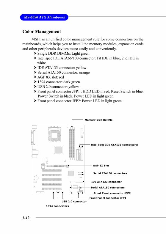
Color ManagementMSI has an unified color management rule for some connectors on the
mainboards, which helps you to install the memory modules, expansion cardsand other peripherals devices more easily and conveniently.
Single DDR DIMMs: Light green Intel spec IDE ATA66/100 connector: 1st IDE in blue, 2nd IDE in
white IDE ATA133 connector: yellow Serial ATA150 connector: orange AGP 8X slot: red 1394 connector: dark green USB 2.0 connector: yellow Front panel connector JFP1 : HDD LED in red, Reset Switch in blue,
Power Switch in black, Power LED in light green. Front panel connector JFP2: Power LED in light green.
Memory DDR DIMMs
Front Panel connector JFP2
USB 2.0 connector
AGP 8X Slot
Intel spec IDE ATA133 connectors:
Serial ATA150 connectors
Front Panel connector JFP1
1394 connectors
IDE ATA133 connector
Serial ATA150 connectors
1-13
Getting Started
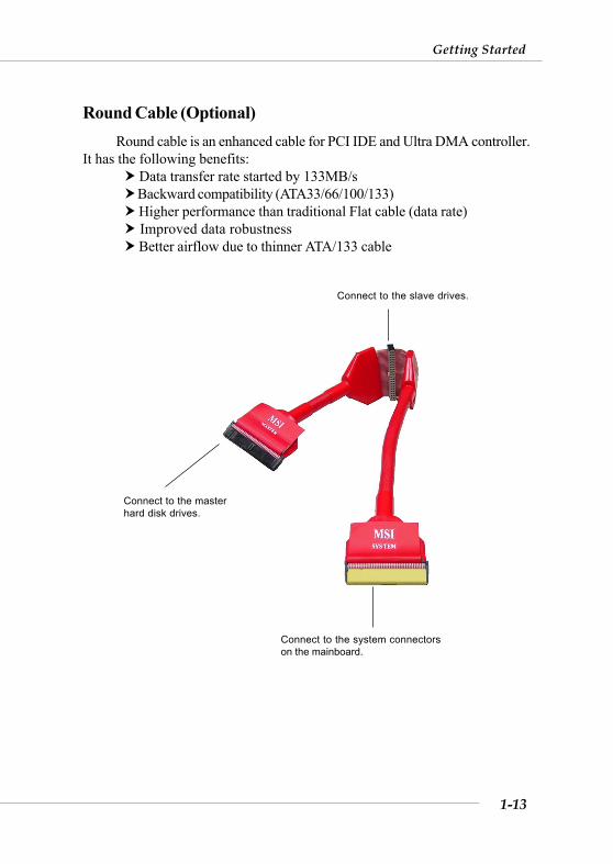
Round Cable (Optional)Round cable is an enhanced cable for PCI IDE and Ultra DMA controller.
It has the following benefits: Data transfer rate started by 133MB/s Backward compatibility (ATA33/66/100/133) Higher performance than traditional Flat cable (data rate) Improved data robustness Better airflow due to thinner ATA/133 cable
Connect to the slave drives.
Connect to the masterhard disk drives.
Connect to the system connectorson the mainboard.
1-14
MS-6590 ATX Mainboard
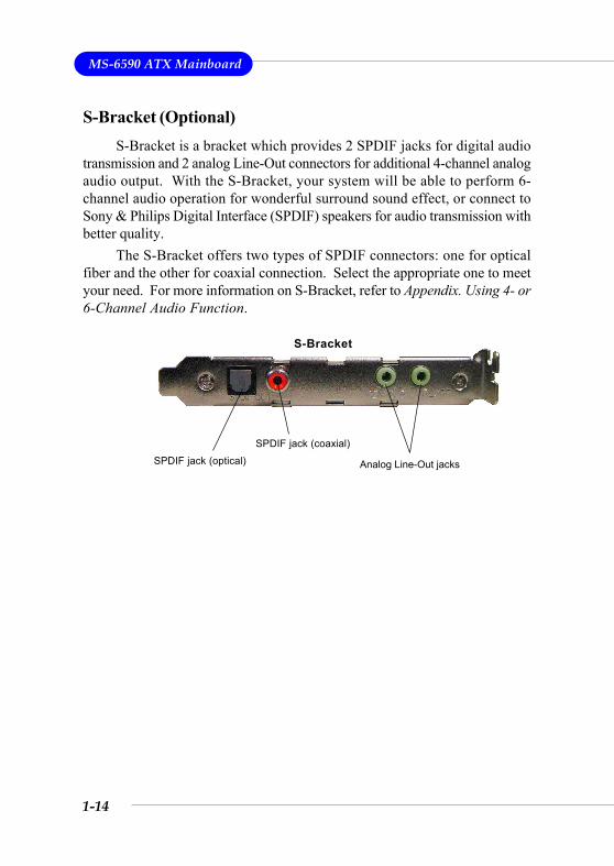
S-Bracket (Optional)S-Bracket is a bracket which provides 2 SPDIF jacks for digital audio
transmission and 2 analog Line-Out connectors for additional 4-channel analogaudio output. With the S-Bracket, your system will be able to perform 6-channel audio operation for wonderful surround sound effect, or connect toSony & Philips Digital Interface (SPDIF) speakers for audio transmission withbetter quality.
The S-Bracket offers two types of SPDIF connectors: one for opticalfiber and the other for coaxial connection. Select the appropriate one to meetyour need. For more information on S-Bracket, refer to Appendix. Using 4- or6-Channel Audio Function.
S-Bracket
SPDIF jack (optical)SPDIF jack (coaxial)
Analog Line-Out jacks
2-1
Hardware Setup
Chapter 2. HardwareSetup
This chapter tells you how to install the CPU, memorymodules, and expansion cards, as well as how to setup thejumpers on the mainboard. Also, it provides the instructions onconnecting the peripheral devices, such as the mouse, keyboard,etc.
While doing the installation, be careful in holding thecomponents and follow the installation procedures.
Hardware Setup
2-2
MS-6590 ATX Mainboard
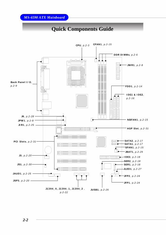
Quick Components Guide
JAUD1, p.2-25
J3, p.2-20
DDR DIMMs, p.2-6
CPU, p.2-3
Back Panel I/O,p.2-9
CFAN1, p.2-15
FDD1, p.2-14
IDE3, p.2-18
JFP2, p.2-24
JFP1, p.2-24
JUSB1, p.2-26
JIR1, p.2-25
JBAT1, p.2-29
AGP Slot, p.2-31
JSP3, p.2-20
PCI Slots, p.2-31
IDE1 & IDE2,p.2-16
NBFAN1, p.2-15
SER1, p.2-18
JLED1, p.2-27
SER2, p.2-18
SFAN1, p.2-15
JWR1, p.2-8
J1394_0, J1394_1, J1394_2 , p.2-22
J6, p.2-28
JS1, p.2-30
SATA2, p.2-17SATA1, p.2-17
JPW1, p.2-8
2-3
Hardware Setup
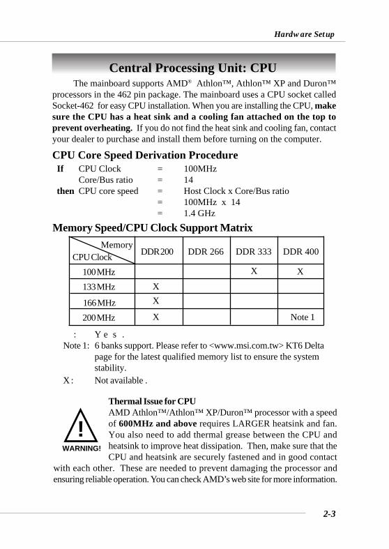
Central Processing Unit: CPU
CPU Core Speed Derivation Procedure If CPU Clock = 100MHz
Core/Bus ratio = 14 then CPU core speed = Host Clock x Core/Bus ratio
= 100MHz x 14= 1.4 GHz
The mainboard supports AMD® Athlon™, Athlon™ XP and Duron™processors in the 462 pin package. The mainboard uses a CPU socket calledSocket-462 for easy CPU installation. When you are installing the CPU, makesure the CPU has a heat sink and a cooling fan attached on the top toprevent overheating. If you do not find the heat sink and cooling fan, contactyour dealer to purchase and install them before turning on the computer.
Thermal Issue for CPUAMD Athlon™/Athlon™ XP/Duron™ processor with a speedof 600MHz and above requires LARGER heatsink and fan.You also need to add thermal grease between the CPU andheatsink to improve heat dissipation. Then, make sure that theCPU and heatsink are securely fastened and in good contact
with each other. These are needed to prevent damaging the processor andensuring reliable operation. You can check AMD’s web site for more information.
!WARNING!
Memory Speed/CPU Clock Support Matrix
○ : Yes.Note 1: 6 banks support. Please refer to <www.msi.com.tw> KT6 Delta
page for the latest qualified memory list to ensure the systemstability.
X : Not available .
CPU ClockMemory
DDR 266
133 MHz
DDR 333 DDR 400
166 MHz200 MHz
○
○
○
○
○
Note 1
DDR 200
X ○
100 MHz ○ X○
XX
X
○
○
2-4
MS-6590 ATX Mainboard
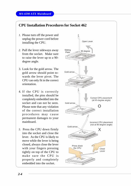
CPU Installation Procedures for Socket 462
1. Please turn off the power andunplug the power cord beforeinstalling the CPU.
2. Pull the lever sideways awayfrom the socket. Make sureto raise the lever up to a 90-degree angle.
3. Look for the gold arrow. Thegold arrow should point to-wards the lever pivot. TheCPU can only fit in the correctorientation.
4. If the CPU is correctlyinstalled, the pins should becompletely embedded into thesocket and can not be seen.Please note that any violationof the correct installationp rocedu re s may causepermanent damages to yourmainboard.
5. Press the CPU down firmlyinto the socket and close thelever. As the CPU is likely tomove while the lever is beingclosed, always close the leverwith your fingers pressingtightly on top of the CPU tomake sure the CPU i sproperly and completelyembedded into the socket.
Open Lever
90 degreeSliding Plate
Close Lever
Press downthe CPU
Gold arrow
Gold arrow
Gold arrow
Incorrect CPU placement(not at 90-degree angle)
X
O
2-5
Hardware Setup
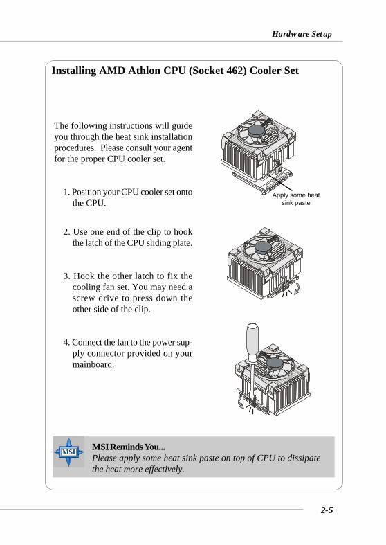
The following instructions will guideyou through the heat sink installationprocedures. Please consult your agentfor the proper CPU cooler set.
1. Position your CPU cooler set ontothe CPU.
2. Use one end of the clip to hookthe latch of the CPU sliding plate.
3. Hook the other latch to fix thecooling fan set. You may need ascrew drive to press down theother side of the clip.
4. Connect the fan to the power sup-ply connector provided on yourmainboard.
Installing AMD Athlon CPU (Socket 462) Cooler Set
Apply some heatsink paste
MSI Reminds You...Please apply some heat sink paste on top of CPU to dissipatethe heat more effectively.
2-6
MS-6590 ATX Mainboard
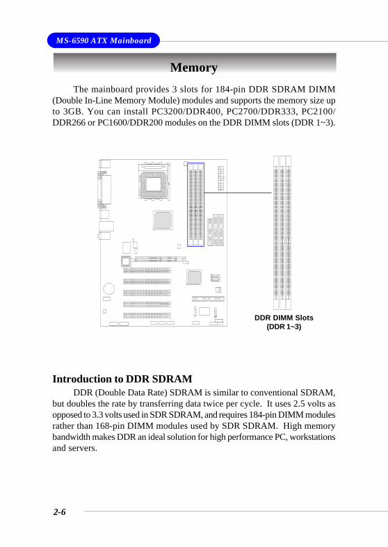
The mainboard provides 3 slots for 184-pin DDR SDRAM DIMM(Double In-Line Memory Module) modules and supports the memory size upto 3GB. You can install PC3200/DDR400, PC2700/DDR333, PC2100/DDR266 or PC1600/DDR200 modules on the DDR DIMM slots (DDR 1~3).
Memory
DDR DIMM Slots(DDR 1~3)
Introduction to DDR SDRAMDDR (Double Data Rate) SDRAM is similar to conventional SDRAM,
but doubles the rate by transferring data twice per cycle. It uses 2.5 volts asopposed to 3.3 volts used in SDR SDRAM, and requires 184-pin DIMM modulesrather than 168-pin DIMM modules used by SDR SDRAM. High memorybandwidth makes DDR an ideal solution for high performance PC, workstationsand servers.
2-7
Hardware Setup
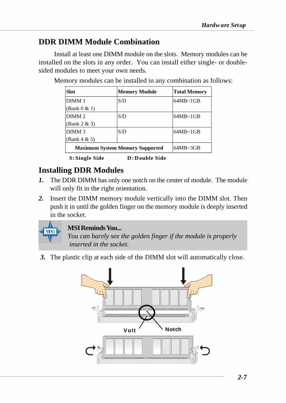
Installing DDR Modules1. The DDR DIMM has only one notch on the center of module. The module
will only fit in the right orientation.2. Insert the DIMM memory module vertically into the DIMM slot. Then
push it in until the golden finger on the memory module is deeply insertedin the socket.
3. The plastic clip at each side of the DIMM slot will automatically close.
MSI Reminds You...You can barely see the golden finger if the module is properly inserted in the socket.
Volt Notch
Install at least one DIMM module on the slots. Memory modules can beinstalled on the slots in any order. You can install either single- or double-sided modules to meet your own needs.
Memory modules can be installed in any combination as follows:Slot Memory Module Total Memory
DIMM 1 (Bank 0 & 1)
S/D 64MB~1GB
DIMM 2 (Bank 2 & 3)
S/D 64MB~1GB
DIMM 3 (Bank 4 & 5)
S/D 64MB~1GB
Maximum System Memory Supported 64MB~3GB
DDR DIMM Module Combination
S: Single Side D: Double Side
2-8
MS-6590 ATX Mainboard
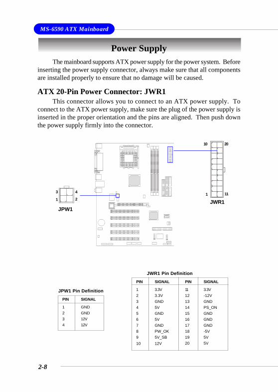
Power SupplyThe mainboard supports ATX power supply for the power system. Before
inserting the power supply connector, always make sure that all componentsare installed properly to ensure that no damage will be caused.
ATX 20-Pin Power Connector: JWR1This connector allows you to connect to an ATX power supply. To
connect to the ATX power supply, make sure the plug of the power supply isinserted in the proper orientation and the pins are aligned. Then push downthe power supply firmly into the connector.
PIN SIGNAL
11 3.3V12 -12V13 GND14 PS_ON15 GND16 GND17 GND18 -5V19 5V20 5V
PIN SIGNAL
1 3.3V2 3.3V3 GND4 5V5 GND6 5V7 GND8 PW_OK9 5V_SB10 12V
JWR1 Pin Definition
JWR1
10
1
20
11
JPW1
1
3 4
2
PIN SIGNAL
1 GND2 GND3 12V4 12V
JPW1 Pin Definition
2-9
Hardware Setup
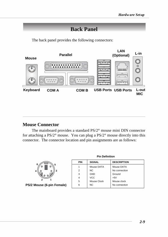
The back panel provides the following connectors:
Back Panel
Mouse ConnectorThe mainboard provides a standard PS/2® mouse mini DIN connector
for attaching a PS/2® mouse. You can plug a PS/2® mouse directly into thisconnector. The connector location and pin assignments are as follows:
PIN SIGNAL DESCRIPTION
1 Mouse DATA Mouse DATA2 NC No connection3 GND Ground4 VCC +5V5 Mouse Clock Mouse clock6 NC No connection
Pin Definition
PS/2 Mouse (6-pin Female)2 1
34
56
MouseParallel
USB PortsCOM A COM B USB PortsKeyboard L-out
L-in
MIC
LAN(Optional)
2-10
MS-6590 ATX Mainboard
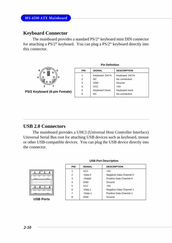
Keyboard ConnectorThe mainboard provides a standard PS/2® keyboard mini DIN connector
for attaching a PS/2® keyboard. You can plug a PS/2® keyboard directly intothis connector.
PIN SIGNAL DESCRIPTION
1 Keyboard DATA Keyboard DATA2 NC No connection3 GND Ground4 VCC +5V5 Keyboard Clock Keyboard clock6 NC No connection
Pin Definition
PS/2 Keyboard (6-pin Female)2 1
34
56
USB 2.0 ConnectorsThe mainboard provides a UHCI (Universal Host Controller Interface)
Universal Serial Bus root for attaching USB devices such as keyboard, mouseor other USB-compatible devices. You can plug the USB device directly intothe connector.
PIN SIGNAL DESCRIPTION
1 VCC +5V2 -Data 0 Negative Data Channel 03 +Data0 Positive Data Channel 04 GND Ground5 VCC +5V6 -Data 1 Negative Data Channel 17 +Data 1 Positive Data Channel 18 GND Ground
USB Port Description
USB Ports
1 2 3 4
5 6 7 8
2-11
Hardware Setup
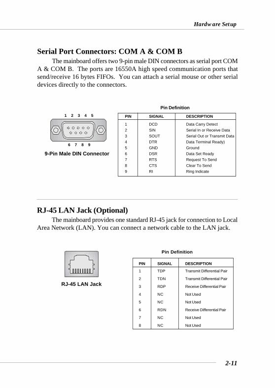
Serial Port Connectors: COM A & COM BThe mainboard offers two 9-pin male DIN connectors as serial port COM
A & COM B. The ports are 16550A high speed communication ports thatsend/receive 16 bytes FIFOs. You can attach a serial mouse or other serialdevices directly to the connectors.
PIN SIGNAL DESCRIPTION
1 DCD Data Carry Detect2 SIN Serial In or Receive Data3 SOUT Serial Out or Transmit Data4 DTR Data Terminal Ready)5 GND Ground6 DSR Data Set Ready7 RTS Request To Send8 CTS Clear To Send9 RI Ring Indicate
Pin Definition
9-Pin Male DIN Connector
1 2 3 4 5
6 7 8 9
RJ-45 LAN Jack (Optional)The mainboard provides one standard RJ-45 jack for connection to Local
Area Network (LAN). You can connect a network cable to the LAN jack.
Pin Definition
PIN SIGNAL DESCRIPTION
1 TDP Transmit Differential Pair
2 TDN Transmit Differential Pair
3 RDP Receive Differential Pair
4 NC Not Used
5 NC Not Used
6 RDN Receive Differential Pair
7 NC Not Used
8 NC Not Used
RJ-45 LAN Jack
2-12
MS-6590 ATX Mainboard
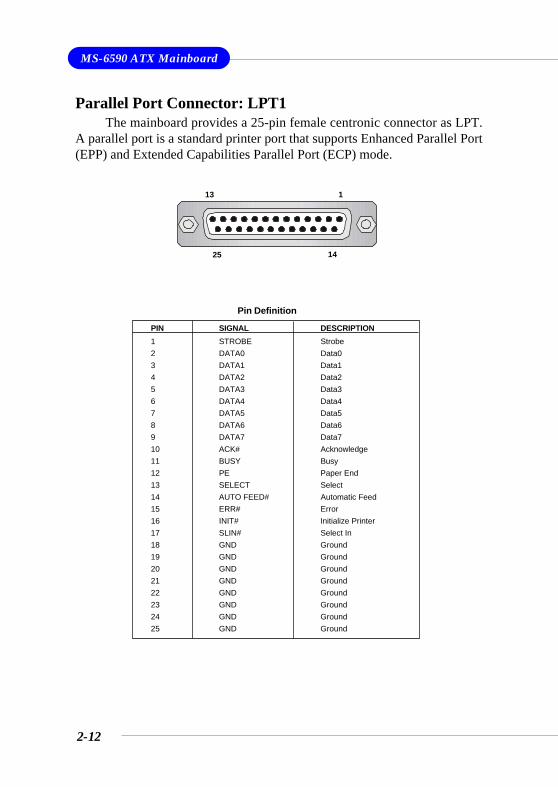
Parallel Port Connector: LPT1The mainboard provides a 25-pin female centronic connector as LPT.
A parallel port is a standard printer port that supports Enhanced Parallel Port(EPP) and Extended Capabilities Parallel Port (ECP) mode.
13 1
1425
PIN SIGNAL DESCRIPTION1 STROBE Strobe2 DATA0 Data03 DATA1 Data14 DATA2 Data25 DATA3 Data36 DATA4 Data47 DATA5 Data58 DATA6 Data69 DATA7 Data710 ACK# Acknowledge11 BUSY Busy12 PE Paper End13 SELECT Select14 AUTO FEED# Automatic Feed15 ERR# Error16 INIT# Initialize Printer17 SLIN# Select In18 GND Ground19 GND Ground20 GND Ground21 GND Ground22 GND Ground23 GND Ground24 GND Ground25 GND Ground
Pin Definition
2-13
Hardware Setup
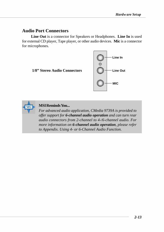
Audio Port ConnectorsLine Out is a connector for Speakers or Headphones. Line In is used
for external CD player, Tape player, or other audio devices. Mic is a connectorfor microphones.
1/8” Stereo Audio Connectors
MSI Reminds You...For advanced audio application, CMedia 9739A is provided tooffer support for 6-channel audio operation and can turn rearaudio connectors from 2-channel to 4-/6-channel audio. Formore information on 6-channel audio operation, please referto Appendix. Using 4- or 6-Channel Audio Function.
Line Out
Line In
MIC
2-14
MS-6590 ATX Mainboard
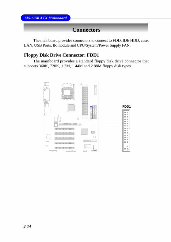
The mainboard provides connectors to connect to FDD, IDE HDD, case,LAN, USB Ports, IR module and CPU/System/Power Supply FAN.
Floppy Disk Drive Connector: FDD1The mainboard provides a standard floppy disk drive connector that
supports 360K, 720K, 1.2M, 1.44M and 2.88M floppy disk types.
Connectors
FDD1
2-15
Hardware Setup
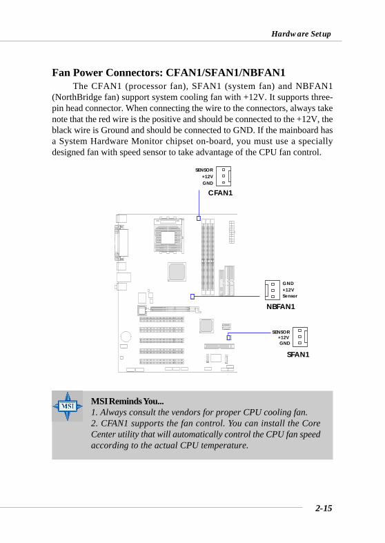
Fan Power Connectors: CFAN1/SFAN1/NBFAN1The CFAN1 (processor fan), SFAN1 (system fan) and NBFAN1
(NorthBridge fan) support system cooling fan with +12V. It supports three-pin head connector. When connecting the wire to the connectors, always takenote that the red wire is the positive and should be connected to the +12V, theblack wire is Ground and should be connected to GND. If the mainboard hasa System Hardware Monitor chipset on-board, you must use a speciallydesigned fan with speed sensor to take advantage of the CPU fan control.
CFAN1
SENSOR+12VGND
SFAN1
SENSOR+12VGND
MSI Reminds You...1. Always consult the vendors for proper CPU cooling fan.2. CFAN1 supports the fan control. You can install the CoreCenter utility that will automatically control the CPU fan speedaccording to the actual CPU temperature.
NBFAN1
+12VGND
Sensor
2-16
MS-6590 ATX Mainboard
IDE1 IDE2
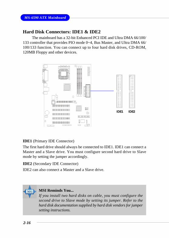
Hard Disk Connectors: IDE1 & IDE2The mainboard has a 32-bit Enhanced PCI IDE and Ultra DMA 66/100/
133 controller that provides PIO mode 0~4, Bus Master, and Ultra DMA 66/100/133 function. You can connect up to four hard disk drives, CD-ROM,120MB Floppy and other devices.
IDE1 (Primary IDE Connector)The first hard drive should always be connected to IDE1. IDE1 can connect aMaster and a Slave drive. You must configure second hard drive to Slavemode by setting the jumper accordingly.
IDE2 (Secondary IDE Connector)IDE2 can also connect a Master and a Slave drive.
MSI Reminds You...If you install two hard disks on cable, you must configure thesecond drive to Slave mode by setting its jumper. Refer to thehard disk documentation supplied by hard disk vendors for jumpersetting instructions.
2-17
Hardware Setup
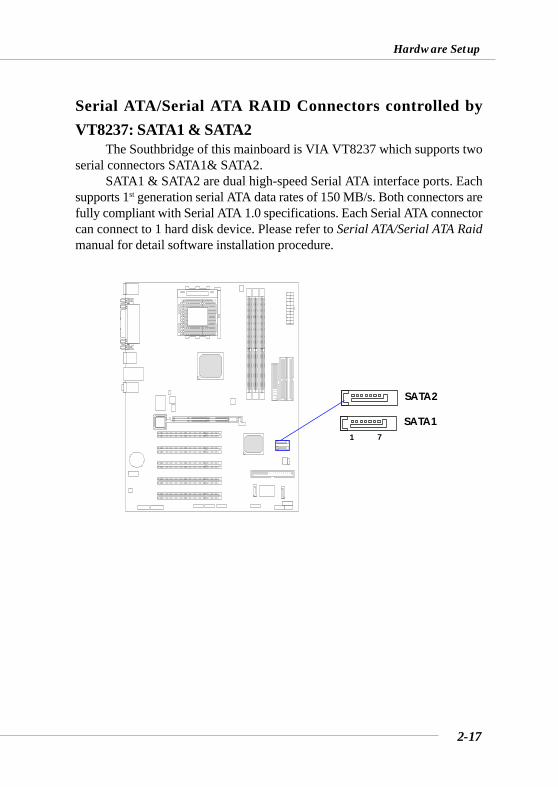
Serial ATA/Serial ATA RAID Connectors controlled byVT8237: SATA1 & SATA2
The Southbridge of this mainboard is VIA VT8237 which supports twoserial connectors SATA1& SATA2.
SATA1 & SATA2 are dual high-speed Serial ATA interface ports. Eachsupports 1st generation serial ATA data rates of 150 MB/s. Both connectors arefully compliant with Serial ATA 1.0 specifications. Each Serial ATA connectorcan connect to 1 hard disk device. Please refer to Serial ATA/Serial ATA Raidmanual for detail software installation procedure.
71
SATA2
SATA1
2-18
MS-6590 ATX Mainboard
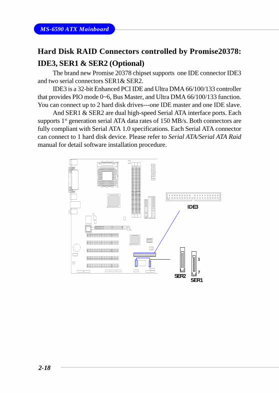
Hard Disk RAID Connectors controlled by Promise20378:IDE3, SER1 & SER2 (Optional)
The brand new Promise 20378 chipset supports one IDE connector IDE3and two serial connectors SER1& SER2.
IDE3 is a 32-bit Enhanced PCI IDE and Ultra DMA 66/100/133 controllerthat provides PIO mode 0~6, Bus Master, and Ultra DMA 66/100/133 function.You can connect up to 2 hard disk drives---one IDE master and one IDE slave.
And SER1 & SER2 are dual high-speed Serial ATA interface ports. Eachsupports 1st generation serial ATA data rates of 150 MB/s. Both connectors arefully compliant with Serial ATA 1.0 specifications. Each Serial ATA connectorcan connect to 1 hard disk device. Please refer to Serial ATA/Serial ATA Raidmanual for detail software installation procedure.
IDE3
SER1
1
7SER2
2-19
Hardware Setup
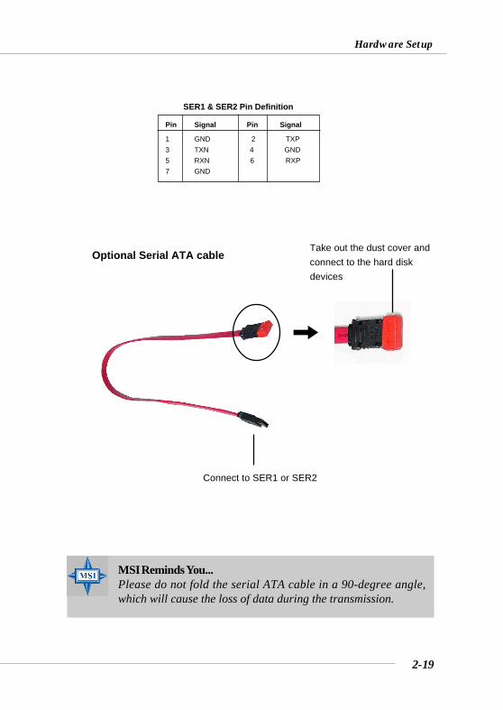
MSI Reminds You...Please do not fold the serial ATA cable in a 90-degree angle,which will cause the loss of data during the transmission.
SER1 & SER2 Pin Definition
Connect to SER1 or SER2
Take out the dust cover andconnect to the hard diskdevices
Optional Serial ATA cable
Pin Signal Pin Signal
1 GND 2 TXP3 TXN 4 GND5 RXN 6 RXP7 GND
2-20
MS-6590 ATX Mainboard
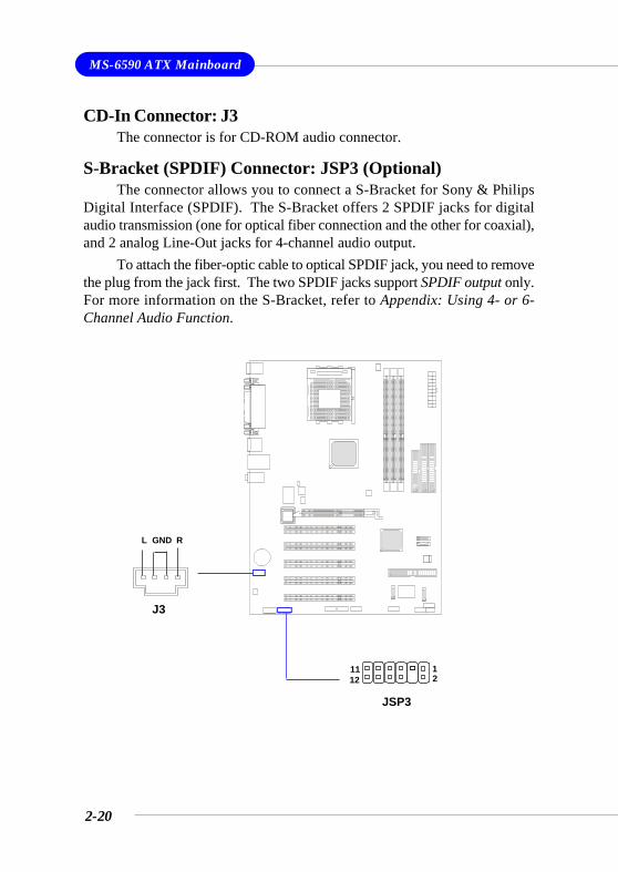
CD-In Connector: J3The connector is for CD-ROM audio connector.
S-Bracket (SPDIF) Connector: JSP3 (Optional)The connector allows you to connect a S-Bracket for Sony & Philips
Digital Interface (SPDIF). The S-Bracket offers 2 SPDIF jacks for digitalaudio transmission (one for optical fiber connection and the other for coaxial),and 2 analog Line-Out jacks for 4-channel audio output.
To attach the fiber-optic cable to optical SPDIF jack, you need to removethe plug from the jack first. The two SPDIF jacks support SPDIF output only.For more information on the S-Bracket, refer to Appendix: Using 4- or 6-Channel Audio Function.
J3
GNDL R
JSP3
1 11 2 12
2-21
Hardware Setup
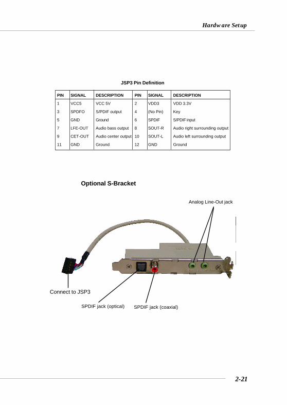
PIN SIGNAL DESCRIPTION PIN SIGNAL DESCRIPTION
1 VCC5 VCC 5V 2 VDD3 VDD 3.3V
3 SPDFO S/PDIF output 4 (No Pin) Key
5 GND Ground 6 SPDIF S/PDIF input
7 LFE-OUT Audio bass output 8 SOUT-R Audio right surrounding output
9 CET-OUT Audio center output 10 SOUT-L Audio left surrounding output
11 GND Ground 12 GND Ground
JSP3 Pin Definition
Optional S-Bracket
SPDIF jack (optical) SPDIF jack (coaxial)
Analog Line-Out jack
Connect to JSP3
2-22
MS-6590 ATX Mainboard
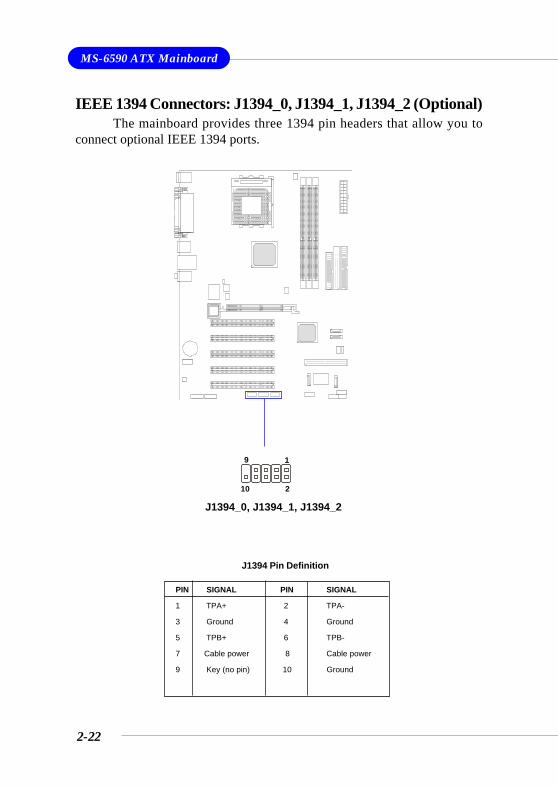
IEEE 1394 Connectors: J1394_0, J1394_1, J1394_2 (Optional)The mainboard provides three 1394 pin headers that allow you to
connect optional IEEE 1394 ports.
J1394_0, J1394_1, J1394_2
1 9
2 10
PIN SIGNAL PIN SIGNAL
1 TPA+ 2 TPA-
3 Ground 4 Ground
5 TPB+ 6 TPB-
7 Cable power 8 Cable power
9 Key (no pin) 10 Ground
J1394 Pin Definition
2-23
Hardware Setup
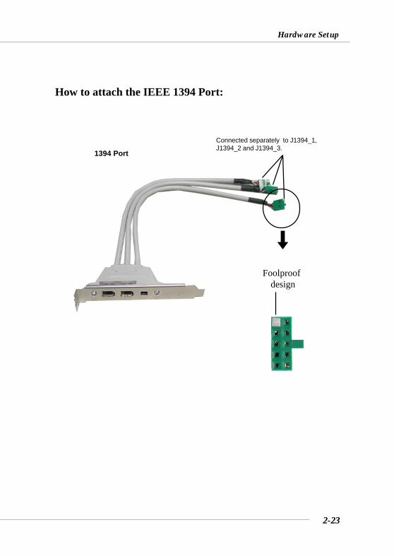
How to attach the IEEE 1394 Port:
Foolproofdesign
Connected separately to J1394_1,J1394_2 and J1394_3.
1394 Port
2-24
MS-6590 ATX Mainboard
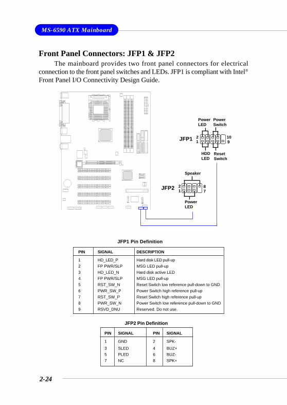
Front Panel Connectors: JFP1 & JFP2The mainboard provides two front panel connectors for electrical
connection to the front panel switches and LEDs. JFP1 is compliant with Intel®
Front Panel I/O Connectivity Design Guide.
12
910JFP1
HDDLED
ResetSwitch
PowerLED
PowerSwitch
PowerLED
Speaker
12
78JFP2
PIN SIGNAL DESCRIPTION
1 HD_LED_P Hard disk LED pull-up2 FP PWR/SLP MSG LED pull-up3 HD_LED_N Hard disk active LED4 FP PWR/SLP MSG LED pull-up5 RST_SW_N Reset Switch low reference pull-down to GND6 PWR_SW_P Power Switch high reference pull-up7 RST_SW_P Reset Switch high reference pull-up8 PWR_SW_N Power Switch low reference pull-down to GND9 RSVD_DNU Reserved. Do not use.
JFP1 Pin Definition
PIN SIGNAL PIN SIGNAL
1 GND 2 SPK-3 SLED 4 BUZ+5 PLED 6 BUZ-7 NC 8 SPK+
JFP2 Pin Definition
2-25
Hardware Setup
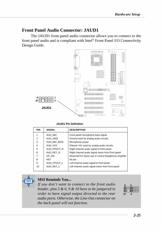
Front Panel Audio Connector: JAUD1The JAUD1 front panel audio connector allows you to connect to the
front panel audio and is compliant with Intel® Front Panel I/O ConnectivityDesign Guide.
PIN SIGNAL DESCRIPTION
1 AUD_MIC Front panel microphone input signal2 AUD_GND Ground used by analog audio circuits3 AUD_MIC_BIAS Microphone power4 AUD_VCC Filtered +5V used by analog audio circuits5 AUD_FPOUT_R Right channel audio signal to front panel6 AUD_RET_R Right channel audio signal return from front panel7 HP_ON Reserved for future use to control headphone amplifier8 KEY No pin9 AUD_FPOUT_L Left channel audio signal to front panel10 AUD_RET_L Left channel audio signal return from front panel
JAUD1 Pin Definition
MSI Reminds You...If you don’t want to connect to the front audioheader, pins 5 & 6, 9 & 10 have to be jumpered inorder to have signal output directed to the rearaudio ports. Otherwise, the Line-Out connector onthe back panel will not function.
5
610
9
JAUD1
12
910
2-26
MS-6590 ATX Mainboard
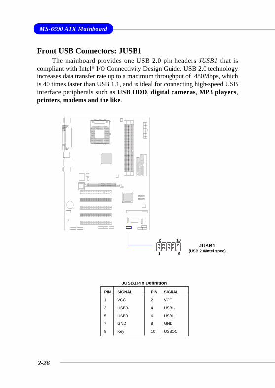
Front USB Connectors: JUSB1The mainboard provides one USB 2.0 pin headers JUSB1 that is
compliant with Intel® I/O Connectivity Design Guide. USB 2.0 technologyincreases data transfer rate up to a maximum throughput of 480Mbps, whichis 40 times faster than USB 1.1, and is ideal for connecting high-speed USBinterface peripherals such as USB HDD, digital cameras, MP3 players,printers, modems and the like.
JUSB1(USB 2.0/Intel spec)
PIN SIGNAL PIN SIGNAL
1 VCC 2 VCC
3 USB0- 4 USB1-
5 USB0+ 6 USB1+
7 GND 8 GND
9 Key 10 USBOC
JUSB1 Pin Definition
1 9
2 10
2-27
Hardware Setup
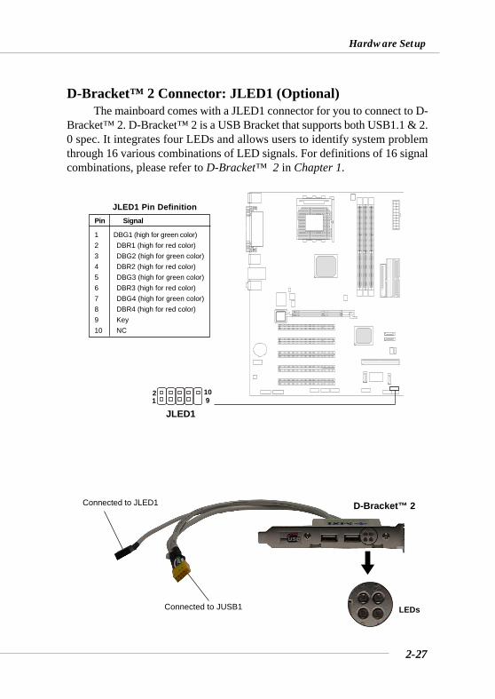
D-Bracket™ 2 Connector: JLED1 (Optional)The mainboard comes with a JLED1 connector for you to connect to D-
Bracket™ 2. D-Bracket™ 2 is a USB Bracket that supports both USB1.1 & 2.0 spec. It integrates four LEDs and allows users to identify system problemthrough 16 various combinations of LED signals. For definitions of 16 signalcombinations, please refer to D-Bracket™ 2 in Chapter 1.
JLED1 1 9 2 10
D-Bracket™ 2Connected to JLED1
LEDsConnected to JUSB1
Pin Signal
1 DBG1 (high for green color)2 DBR1 (high for red color)3 DBG2 (high for green color)4 DBR2 (high for red color)5 DBG3 (high for green color)6 DBR3 (high for red color)7 DBG4 (high for green color)8 DBR4 (high for red color)9 Key10 NC
JLED1 Pin Definition
2-28
MS-6590 ATX Mainboard
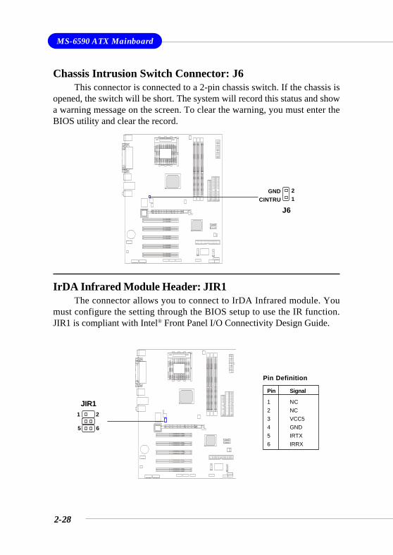
Chassis Intrusion Switch Connector: J6This connector is connected to a 2-pin chassis switch. If the chassis is
opened, the switch will be short. The system will record this status and showa warning message on the screen. To clear the warning, you must enter theBIOS utility and clear the record.
IrDA Infrared Module Header: JIR1The connector allows you to connect to IrDA Infrared module. You
must configure the setting through the BIOS setup to use the IR function.JIR1 is compliant with Intel® Front Panel I/O Connectivity Design Guide.
J6
21
GNDCINTRU
JIR1
65
21
Pin Signal
1 NC2 NC3 VCC54 GND5 IRTX6 IRRX
Pin Definition
2-29
Hardware Setup
The motherboard provides the following jumpers for you to set thecomputer’s function. This section will explain how to change yourmotherboard’s function through the use of jumpers.
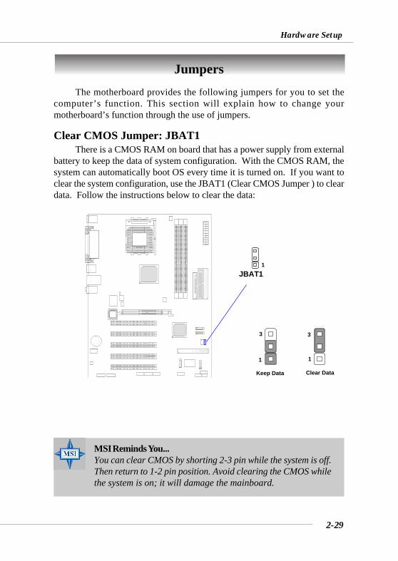
Clear CMOS Jumper: JBAT1There is a CMOS RAM on board that has a power supply from external
battery to keep the data of system configuration. With the CMOS RAM, thesystem can automatically boot OS every time it is turned on. If you want toclear the system configuration, use the JBAT1 (Clear CMOS Jumper ) to cleardata. Follow the instructions below to clear the data:
Jumpers
JBAT11
MSI Reminds You...You can clear CMOS by shorting 2-3 pin while the system is off.Then return to 1-2 pin position. Avoid clearing the CMOS whilethe system is on; it will damage the mainboard.
Keep Data
1
3
Clear Data
1
3
2-30
MS-6590 ATX Mainboard
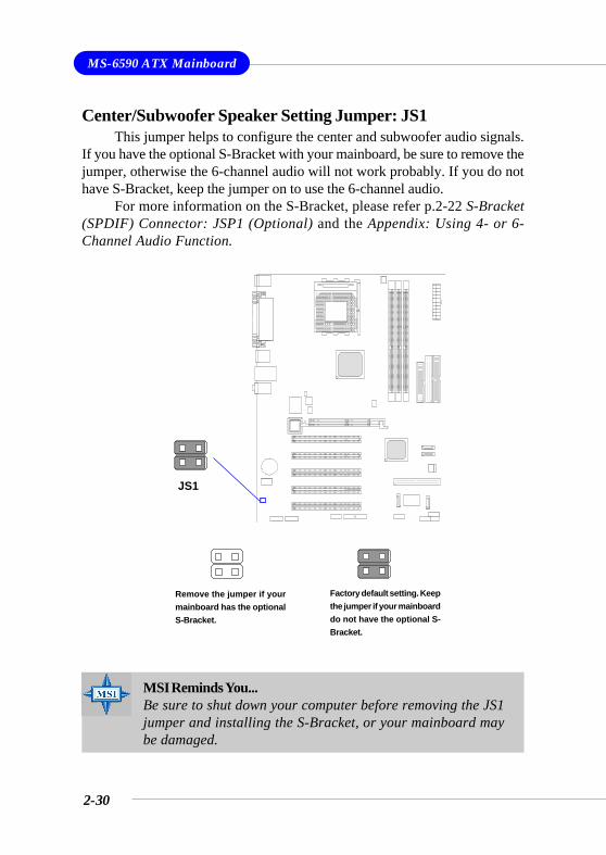
Center/Subwoofer Speaker Setting Jumper: JS1This jumper helps to configure the center and subwoofer audio signals.
If you have the optional S-Bracket with your mainboard, be sure to remove thejumper, otherwise the 6-channel audio will not work probably. If you do nothave S-Bracket, keep the jumper on to use the 6-channel audio.
For more information on the S-Bracket, please refer p.2-22 S-Bracket(SPDIF) Connector: JSP1 (Optional) and the Appendix: Using 4- or 6-Channel Audio Function.
Factory default setting. Keepthe jumper if your mainboarddo not have the optional S-Bracket.
Remove the jumper if yourmainboard has the optionalS-Bracket.
MSI Reminds You...Be sure to shut down your computer before removing the JS1jumper and installing the S-Bracket, or your mainboard maybe damaged.
JS1
2-31
Hardware Setup
Slots
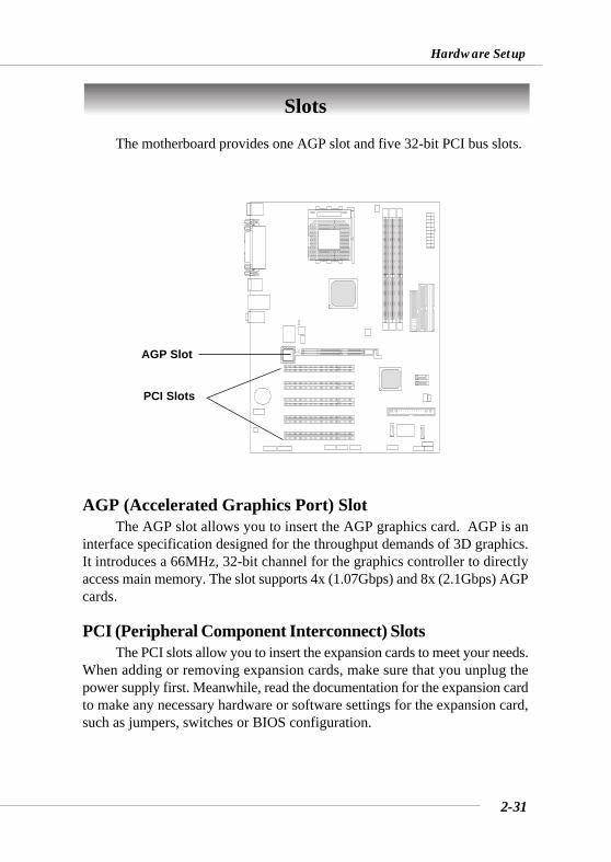
AGP (Accelerated Graphics Port) SlotThe AGP slot allows you to insert the AGP graphics card. AGP is an
interface specification designed for the throughput demands of 3D graphics.It introduces a 66MHz, 32-bit channel for the graphics controller to directlyaccess main memory. The slot supports 4x (1.07Gbps) and 8x (2.1Gbps) AGPcards.
PCI (Peripheral Component Interconnect) SlotsThe PCI slots allow you to insert the expansion cards to meet your needs.
When adding or removing expansion cards, make sure that you unplug thepower supply first. Meanwhile, read the documentation for the expansion cardto make any necessary hardware or software settings for the expansion card,such as jumpers, switches or BIOS configuration.
The motherboard provides one AGP slot and five 32-bit PCI bus slots.
PCI Slots
AGP Slot
2-32
MS-6590 ATX Mainboard
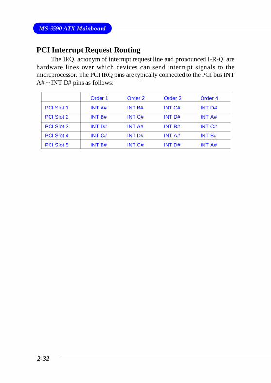
PCI Interrupt Request RoutingThe IRQ, acronym of interrupt request line and pronounced I-R-Q, are
hardware lines over which devices can send interrupt signals to themicroprocessor. The PCI IRQ pins are typically connected to the PCI bus INTA# ~ INT D# pins as follows:
Order 1 Order 2 Order 3 Order 4
PCI Slot 1 INT A# INT B# INT C# INT D#
PCI Slot 2 INT B# INT C# INT D# INT A#
PCI Slot 3 INT D# INT A# INT B# INT C#
PCI Slot 4 INT C# INT D# INT A# INT B#
PCI Slot 5 INT B# INT C# INT D# INT A#
3-1
BIOS Setup
Chapter 3. BIOS Setup
This chapter provides information on the BIOS Setupprogram and allows you to configure the system for optimumuse.
You may need to run the Setup program when:
An error message appears on the screen during the systembooting up, and requests you to run SETUP.
You want to change the default settings for customizedfeatures.
BIOS Setup
3-2
MS-6590 ATX Mainboard
Entering Setup
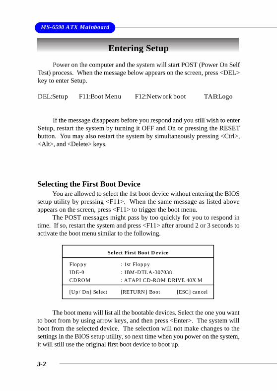
Power on the computer and the system will start POST (Power On SelfTest) process. When the message below appears on the screen, press <DEL>key to enter Setup.
DEL:Setup F11:Boot Menu F12:Network boot TAB:Logo
If the message disappears before you respond and you still wish to enterSetup, restart the system by turning it OFF and On or pressing the RESETbutton. You may also restart the system by simultaneously pressing <Ctrl>,<Alt>, and <Delete> keys.
Selecting the First Boot DeviceYou are allowed to select the 1st boot device without entering the BIOS
setup utility by pressing <F11>. When the same message as listed aboveappears on the screen, press <F11> to trigger the boot menu.
The POST messages might pass by too quickly for you to respond intime. If so, restart the system and press <F11> after around 2 or 3 seconds toactivate the boot menu similar to the following.
The boot menu will list all the bootable devices. Select the one you wantto boot from by using arrow keys, and then press <Enter>. The system willboot from the selected device. The selection will not make changes to thesettings in the BIOS setup utility, so next time when you power on the system,it will still use the original first boot device to boot up.
Select First Boot Device
Floppy : 1st FloppyIDE-0 : IBM-DTLA-307038CDROM : ATAPI CD-ROM DRIVE 40X M
[Up/Dn] Select [RETURN] Boot [ESC] cancel
3-3
BIOS Setup
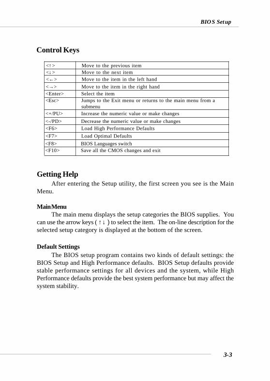
Control Keys
Getting HelpAfter entering the Setup utility, the first screen you see is the Main
Menu.
Main MenuThe main menu displays the setup categories the BIOS supplies. You
can use the arrow keys ( ↑↓ ) to select the item. The on-line description for theselected setup category is displayed at the bottom of the screen.
Default SettingsThe BIOS setup program contains two kinds of default settings: the
BIOS Setup and High Performance defaults. BIOS Setup defaults providestable performance settings for all devices and the system, while HighPerformance defaults provide the best system performance but may affect thesystem stability.
<↑> Move to the previous item<↓> Move to the next item<←> Move to the item in the left hand<→> Move to the item in the right hand<Enter> Select the item<Esc> Jumps to the Exit menu or returns to the main menu from a
<+/PU> Increase the numeric value or make changes<-/PD> Decrease the numeric value or make changes<F6> Load High Performance Defaults<F7> Load Optimal Defaults<F8> BIOS Languages switch<F10> Save all the CMOS changes and exit
submenu
3-4
MS-6590 ATX Mainboard
The Main Menu
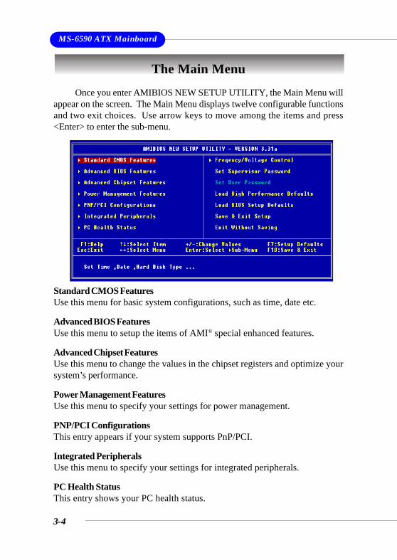
Standard CMOS FeaturesUse this menu for basic system configurations, such as time, date etc.
Advanced BIOS FeaturesUse this menu to setup the items of AMI® special enhanced features.
Advanced Chipset FeaturesUse this menu to change the values in the chipset registers and optimize yoursystem’s performance.
Power Management FeaturesUse this menu to specify your settings for power management.
PNP/PCI ConfigurationsThis entry appears if your system supports PnP/PCI.
Integrated PeripheralsUse this menu to specify your settings for integrated peripherals.
PC Health StatusThis entry shows your PC health status.
Once you enter AMIBIOS NEW SETUP UTILITY, the Main Menu willappear on the screen. The Main Menu displays twelve configurable functionsand two exit choices. Use arrow keys to move among the items and press<Enter> to enter the sub-menu.
3-5
BIOS Setup
Frequency/Voltage ControlUse this menu to specify your settings for frequency/voltage control.
Set Supervisor PasswordUse this menu to set Supervisor Password.
Set User PasswordUse this menu to set User Password.
Load High Performance DefaultsUse this menu to load the BIOS values for the best system performance, butthe system stability may be affected.
Load BIOS Setup DefaultsUse this menu to load factory default settings into the BIOS for stable systemperformance operations.
Save & Exit SetupSave changes to CMOS and exit setup.
Exit Without SavingAbandon all changes and exit setup.
3-6
MS-6590 ATX Mainboard
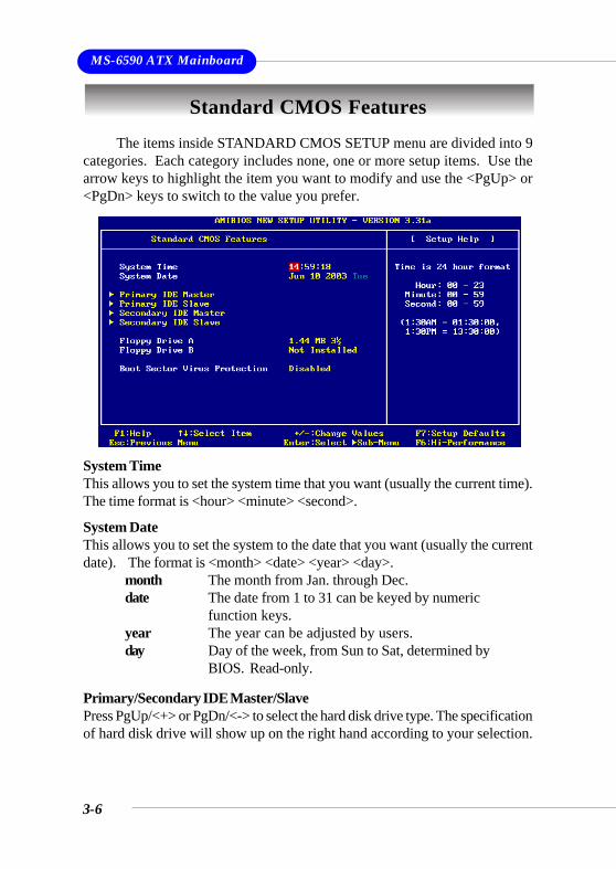
Standard CMOS FeaturesThe items inside STANDARD CMOS SETUP menu are divided into 9
categories. Each category includes none, one or more setup items. Use thearrow keys to highlight the item you want to modify and use the <PgUp> or<PgDn> keys to switch to the value you prefer.
System TimeThis allows you to set the system time that you want (usually the current time).The time format is <hour> <minute> <second>.
System DateThis allows you to set the system to the date that you want (usually the currentdate). The format is <month> <date> <year> <day>.
month The month from Jan. through Dec.date The date from 1 to 31 can be keyed by numeric
function keys.year The year can be adjusted by users.day Day of the week, from Sun to Sat, determined by
BIOS. Read-only.
Primary/Secondary IDE Master/SlavePress PgUp/<+> or PgDn/<-> to select the hard disk drive type. The specificationof hard disk drive will show up on the right hand according to your selection.
3-7
BIOS Setup
Type Select how to define the HDD parametersCylinders Enter cylinder numberHeads Enter head numberWrite Precompensation Enter write precomp cylinderSectors Enter sector numberMaximum Capacity Read the maximal HDD capacityLBA Mode Select Auto for a hard disk > 512 MB un-
der Windows and DOS, or Disabled un-der Netware and UNIX
Block Mode Select Auto to enhance the hard diskperformance
Fast Programmed I/O Select Auto to enhance hard disk perfor-Modes mance by optimizing the hard disk timing32 Bit Transfer Mode Enable 32 bit to maximize the IDE hard
disk data transfer rate
Floppy Drive A:/B:This item allows you to set the type of floppy drives installed. Availableoptions: Not Installed, 1.2 MB 5¼, 720 KB 3½, 1.44 MB 3½ and 2.88 MB 3½.
Boot Sector Virus ProtectionThe item is to set the Virus Warning feature for IDE Hard Disk boot sectorprotection. When Enabled, BIOS will issue a virus warning message and beepif a write to the boot sector or the partition table of the HDD is attempted.Setting options: Disabled and Enabled.
MSI Reminds You...This feature only protects the boot sector, not the whole harddisk.
3-8
MS-6590 ATX Mainboard
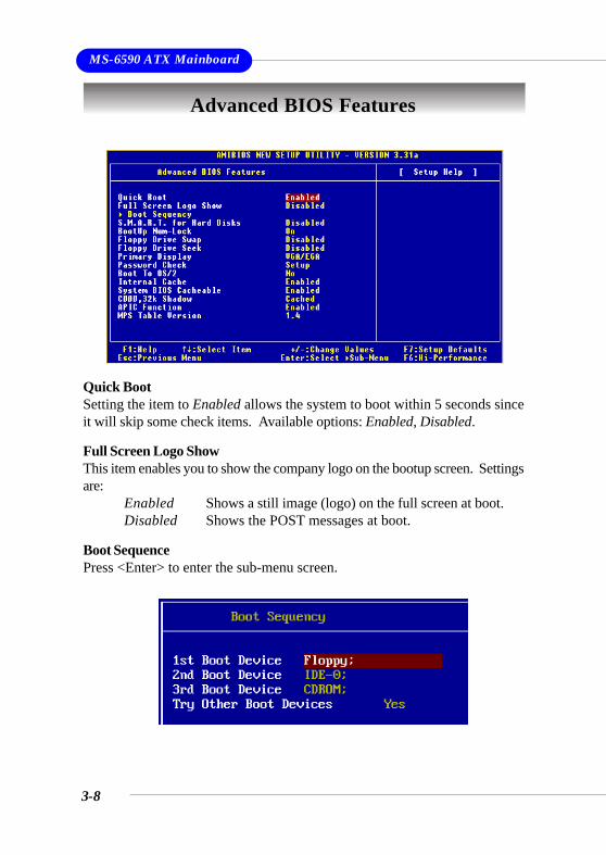
Advanced BIOS Features
Quick BootSetting the item to Enabled allows the system to boot within 5 seconds sinceit will skip some check items. Available options: Enabled, Disabled.
Full Screen Logo ShowThis item enables you to show the company logo on the bootup screen. Settingsare:
Enabled Shows a still image (logo) on the full screen at boot.Disabled Shows the POST messages at boot.
Boot SequencePress <Enter> to enter the sub-menu screen.
3-9
BIOS Setup
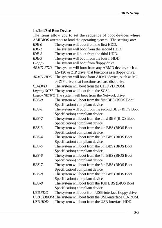
1st/2nd/3rd Boot DeviceThe items allow you to set the sequence of boot devices whereAMIBIOS attempts to load the operating system. The settings are:IDE-0 The system will boot from the first HDD.IDE-1 The system will boot from the second HDD.IDE-2 The system will boot from the third HDD.IDE-3 The system will boot from the fourth HDD.Floppy The system will boot from floppy drive.ARMD-FDD The system will boot from any ARMD device, such as
LS-120 or ZIP drive, that functions as a floppy drive.ARMD-HDD The system will boot from ARMD device, such as MO
or ZIP drive, that functions as hard disk drive.CD/DVD The system will boot from the CD/DVD ROM.Legacy SCSI The system will boot from the SCSI.Legacy NETWO The system will boot from the Network drive.BBS-0 The system will boot from the first BBS (BIOS Boot
Specification) compliant device.BBS-1 The system will boot from the second BBS (BIOS Boot
Specification) compliant device.BBS-2 The system will boot from the third BBS (BIOS Boot
Specification) compliant device.BBS-3 The system will boot from the 4th BBS (BIOS Boot
Specification) compliant device.BBS-4 The system will boot from the 5th BBS (BIOS Boot
Specification) compliant device.BBS-5 The system will boot from the 6th BBS (BIOS Boot
Specification) compliant device.BBS-6 The system will boot from the 7th BBS (BIOS Boot
Specification) compliant device.BBS-7 The system will boot from the 8th BBS (BIOS Boot
Specification) compliant device.BBS-8 The system will boot from the 9th BBS (BIOS Boot
Specification) compliant device.BBS-9 The system will boot from the 10th BBS (BIOS Boot
Specification) compliant device.USB FDD The system will boot from USB-interface floppy drive.USB CDROM The system will boot from the USB-interface CD-ROM.USB HDD The system will boot from the USB-interface HDD.
3-10
MS-6590 ATX Mainboard
USB RMD-FDD The system will boot from any USB-interface ARMDdevice, such as LS-120 or ZIP drive, that functions as afloppy drive.
USB RMD-HDD The system will boot from USB-interface ARMDdevice, such as MO or ZIP drive, that functions as harddisk drive.
Disabled Disable this sequence.
Try Other Boot DevicesSetting the option to Yes allows the system to try to boot from otherdevices if the system fails to boot from the 1st/2nd/3rd boot device.
S.M.A.R.T. for Hard DisksThis allows you to activate the S.M.A.R.T. (Self-Monitoring Analysis &Reporting Technology) capability for the hard disks. S.M.A.R.T is a utility thatmonitors your disk status to predict hard disk failure. This gives you anopportunity to move data from a hard disk that is going to fail to a safe placebefore the hard disk becomes offline. Settings: Enabled, Disabled.
BootUp Num-LockThis item is to set the Num Lock status when the system is powered on. Settingto On will turn on the Num Lock key when the system is powered on. Setting toOff will allow end users to use the arrow keys on the numeric keypad. Settingoptions: On, Off.
Floppy Drive SwapSetting to Enabled will swap floppy drives A: and B:.
Floppy Drive SeekThis setting causes the BIOS to search for floppy disk drives at boot time.When enabled, the BIOS will activate the floppy disk drives during the bootprocess: the drive activity light will come on and the head will move back andforth once. First A: will be done and then B: if it exists. Setting options:Disabled, Enabled.
MSI Reminds You...Available settings for “1st/2nd/3rd Boot Device” varydepending on the bootable devices you have installed. Forexample, if you did not install a floppy drive, the setting“Floppy” does not show up.
3-11
BIOS Setup
Primary DisplayThis configures the primary subsystem in the computer. Available options:Mono (monochrome), CGA40x25, CGA80x25, VGA/EGA, Absent.
Password CheckThis specifies the type of AMIBIOS password protection that is implemented.Setting options are described below.
Boot To OS/2This allows you to run the OS/2® operating system with DRAM larger than64MB. When you choose No, you cannot run the OS/2® operating systemwith DRAM larger than 64MB. But it is possible if you choose Yes.
Internal CacheCache memory is additional memory that is much faster than conventionalDRAM (system memory). When the CPU requests data, the system transfersthe requested data from the main DRAM into cache memory, for even fasteraccess by the CPU. The setting controls the internal cache (also known as L1or level 1 cache). Setting to Enabled will speed up the system performance.
System BIOS CacheableSelecting Enabled allows caching of the system BIOS ROM at F0000h-FFFFFh,resulting in better system performance. However, if any program writes to thismemory area, a system error may result. Setting options: Enabled, Disabled.
C000, 32k ShadowThis item specifies how the contents of the adapter ROM named in the item arehandled. Settings are described below:
Option DescriptionSetup The password prompt appears only when end users try to
run Setup.Always A password prompt appears every time when the com-
puter is powered on or when end users try to run Setup.
3-12
MS-6590 ATX Mainboard
APIC FunctionThis field is used to enable or disable the APIC (Advanced ProgrammableInterrupt Controller). Due to compliance to PC2001 design guide, the system isable to run in APIC mode. Enabling APIC mode will expand available IRQsresources for the system. Settings: Enabled, Disabled.
MPS Table VersionThis field allows you to select which MPS (Multi-Processor Specification)version to be used for the operating system. You need to select the MPSversion supported by your operating system. To find out which version to use,consult the vendor of your operating system. Settings: 1.4, 1.1.
Option DescriptionDisabled The specified ROM is not copied to RAM.Enabled The contents of specified ROM are copied to RAM
for faster system performance.Cached The contents of specified ROM are not only copied
to RAM, the contents of the ROM area can be writ-ten to and read from cache memory.
3-13
BIOS Setup
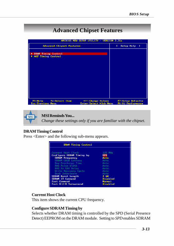
Advanced Chipset Features
DRAM Timing ControlPress <Enter> and the following sub-menu appears.
Current Host ClockThis item shows the current CPU frequency.
Configure SDRAM Timing bySelects whether DRAM timing is controlled by the SPD (Serial PresenceDetect) EEPROM on the DRAM module. Setting to SPD enables SDRAM
MSI Reminds You...Change these settings only if you are familiar with the chipset.
3-14
MS-6590 ATX Mainboard
Frequency, SDRAM CAS# Latency, Row Precharge Time, RAS PulseWidth, RAS to CAS Delay and SDRAM Bank Interleave automatically tobe determined by BIOS based on the configurations on the SPD. SelectingUser allows users to configure these fields manually.
SDRAM FrequencyUse this item to configure the clock frequency of the installed SDRAM.Settings options: 200MHz, 266MHz, 333MHz, 400MHz, Auto.
SDRAM CAS# LatencyThis controls the timing delay (in clock cycles) before SDRAM startsa read command after receiving it. Settings: Auto, 1.5, 2, 2.5, 3.0(clocks). 2 (clocks) increases the system performance the most while 3(clocks) provides the most stable performance.
Row Precharge TimeThis item controls the number of cycles for Row Address Strobe (RAS)to be allowed to precharge. If insufficient time is allowed for the RASto accumulate its charge before DRAM refresh, refreshing may beincomplete and DRAM may fail to retain data. This item applies onlywhen synchronous DRAM is installed in the system. Available settings:Auto, 2, 3, 4, 5.
RAS Pulse WidthThis setting allows you to select the number of clock cycles allottedfor the RAS pulse width, according to DRAM specifications. The lessthe clock cycles, the faster the DRAM performance. Settings: Auto, 6,7, 8, 9.
RAS to CAS DelayWhen DRAM is refreshed, both rows and columns are addressedseparately. This setup item allows you to determine the timing of thetransition from RAS (row address strobe) to CAS (column addressstrobe). The less the clock cycles, the faster the DRAM performance.Setting options: Auto, 2, 3, 4, 5.
Write Recovery CycleYou may set the write recovery cycle of DRAM. The less the clockcycles, the less time the DRAM recovery cycle writes. Setting options:Auto, 1T, 2T.
3-15
BIOS Setup
Bank InterleaveThis field selects 2-bank or 4-bank interleave for the installed SDRAM.Disable the function if 16MB SDRAM is installed. Settings: Disabled,2-Way and 4-Way.
SDRAM Burst LengthThis setting allows you to set the size of Burst-Length for DRAM. Burstingfeature is a technique that DRAM itself predicts the address of the nextmemory location to be accessed after the first address is accessed. Touse the feature, you need to define the burst length, which is the actuallength of burst plus the starting address and allows internal addresscounter to properly generate the next memory location. The bigger thesize, the faster the DRAM performance. Settings: 4 QW, 8 QW.
SDRAM 1T CommandThis setting controls the SDRAM command rate. Selecting Enabledallows SDRAM signal controller to run at 1T (T=clock cycles) rate.Selecting Disabled makes SDRAM signal controller run at 2T rate. 1T isfaster than 2T. Setting options: Disabled, Enabled.
Fast CommandThis item controls the internal timing of CPU. Selecting Ultra allows CPUto handle data/instructions at the fastest speed. Fast enables CPU tohandle at a faster speed, while Normal let CPU handle them at the slowestrate.
Fast R-2-R TurnaroundBurst read operation can be interrupted by new read of any bank.Random column access is allowed. READ to READ interval is minimum 1CLK. Selecting Enabled to shorten the turnaround interval to improvethe performance. Setting options: Disabled, Enabled.
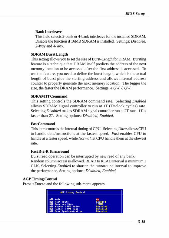
AGP Timing ControlPress <Enter> and the following sub-menu appears.
3-16
MS-6590 ATX Mainboard
AGP ModeThe item sets an appropriate mode for the installed AGP card. Settingoptions: 1x, 2x, 4x, Auto. Select 4x only if your AGP card supports it.
AGP Fast WriteThis option enables or disables the AGP Fast Write feature. The FastWrite technology allows the CPU to write directly to the graphics cardwithout passing anything through the system memory and improves theAGP 4X speed. Select Enabled only when the installed AGP card supportsthis function. Settings: Enabled, Disabled.
AGP Aperture SizeThis setting controls just how much system RAM can be allocated toAGP for video purposes. The aperture is a portion of the PCI memoryaddress range dedicated to graphics memory address space. Host cyclesthat hit the aperture range are forwarded to the AGP without any translation.The option allows the selection of an aperture size of 4MB, 8MB, 16MB,32MB, 64MB, 128MB, and 256 MB.
AGP Master 1 W/S WriteThe field allows users to insert one wait state into the AGP write cycle.Settings: Enabled, Disabled.
AGP Master 1 W/S ReadThe field allows users to insert one wait state into the AGP read cycle.Settings: Enabled, Disabled.
AGP Read SynchronizationThe field allows you to enable or disable the AGP Read Synchronizationfeature. Settings: Enabled, Disabled.
3-17
BIOS Setup
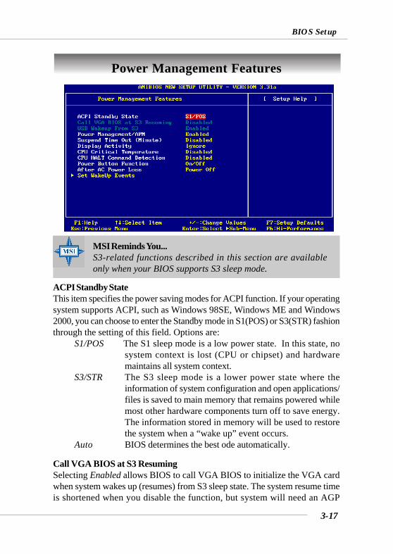
Power Management Features
ACPI Standby StateThis item specifies the power saving modes for ACPI function. If your operatingsystem supports ACPI, such as Windows 98SE, Windows ME and Windows2000, you can choose to enter the Standby mode in S1(POS) or S3(STR) fashionthrough the setting of this field. Options are:
S1/POS The S1 sleep mode is a low power state. In this state, nosystem context is lost (CPU or chipset) and hardwaremaintains all system context.
S3/STR The S3 sleep mode is a lower power state where theinformation of system configuration and open applications/files is saved to main memory that remains powered whilemost other hardware components turn off to save energy.The information stored in memory will be used to restorethe system when a “wake up” event occurs.
Auto BIOS determines the best ode automatically.
Call VGA BIOS at S3 ResumingSelecting Enabled allows BIOS to call VGA BIOS to initialize the VGA cardwhen system wakes up (resumes) from S3 sleep state. The system resume timeis shortened when you disable the function, but system will need an AGP
MSI Reminds You...S3-related functions described in this section are availableonly when your BIOS supports S3 sleep mode.
3-18
MS-6590 ATX Mainboard
driver to initialize the VGA card. Therefore, if the AGP driver of the card doesnot support the initialization feature, the display may work abnormally or notfunction after resuming from S3.
USB Wakeup From S3This item allows the activity of the USB device to wake up the system from S3(Suspend to RAM) sleep state. Settings: Enabled, Disabled.
Power Management/APMSetting to Enabled will activate an Advanced Power Management (APM)device to enhance Max Saving mode and stop CPU internal clock. Settings:Disabled, Enabled.
Suspend Time Out (Minute)After the selected period of system inactivity, all devices except the CPU shutoff. Settings: Disabled, 1, 2, 4, 8, 10, 20, 30, 40, 50, 60.
Display ActivityThese items specify if the BIOS will monitor the activity of the specified hardwareperipheral or component. If set to Monitor, any activity detected on the specifiedhardware peripheral or component will wake up the system or prevent thesystem from entering the power saving modes. Settings: Monitor, Ignore.
CPU Critical TemperatureIf the CPU temperature reaches the upper limit preset in this setting, the warningmechanism will be activated. This helps you to prevent the CPU overheatingproblem.
CPU HALT Command DetectionThis item allows your OS to determine whether the CPU will enter the HALTcommand state. Options: Enabled, Disabled.
Power Button FunctionThis feature sets the function of the power button. Settings are:
On/Off The power button functions as normal power off button.Suspend When you press the power button, the computer enters
the suspend/sleep mode, but if the button is pressed formore than four seconds, the computer is turned off.
After AC Power LossThis setting specifies whether your system will reboot after a power failure or
3-19
BIOS Setup
interrupt occurs. Available settings are:Power Off Leaves the computer in the power off state.Power On Reboots the computer.Last State Restores the system to the previous status before power
failure or interrupt occurred.
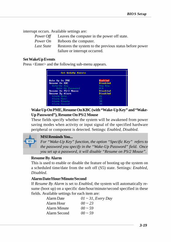
Set WakeUp EventsPress <Enter> and the following sub-menu appears.
Wake Up On PME, Resume On KBC (with “Wake-Up Key” and “Wake-Up Password”), Resume On PS/2 MouseThese fields specify whether the system will be awakened from powersaving modes when activity or input signal of the specified hardwareperipheral or component is detected. Settings: Enabled, Disabled.
MSI Reminds You...For “Wake-Up Key” function, the option “Specific Key” refers tothe password you specify in the “Wake-Up Password” field. Onceyou set up a password, it will disable “Resume on PS/2 Mouse”.
Resume By AlarmThis is used to enable or disable the feature of booting up the system ona scheduled time/date from the soft off (S5) state. Settings: Enabled,Disabled.Alarm Date/Hour/Minute/SecondIf Resume By Alarm is set to Enabled, the system will automatically re-sume (boot up) on a specific date/hour/minute/second specified in thesefields. Available settings for each item are:
Alarm Date 01 ~ 31, Every DayAlarm Hour 00 ~ 23Alarm Minute 00 ~ 59Alarm Second 00 ~ 59

3-20
MS-6590 ATX Mainboard
MSI Reminds You...If you have changed this setting, you must let the system boot upuntil it enters the operating system, before this function will work.
3-21
BIOS Setup
PNP/PCI Configurations
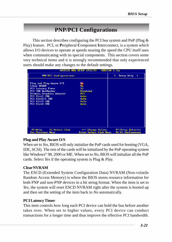
This section describes configuring the PCI bus system and PnP (Plug &Play) feature. PCI, or Peripheral Component Interconnect, is a system whichallows I/O devices to operate at speeds nearing the speed the CPU itself useswhen communicating with its special components. This section covers somevery technical items and it is strongly recommended that only experiencedusers should make any changes to the default settings.
Plug and Play Aware O/SWhen set to Yes, BIOS will only initialize the PnP cards used for booting (VGA,IDE, SCSI). The rest of the cards will be initialized by the PnP operating systemlike Windows® 98, 2000 or ME. When set to No, BIOS will initialize all the PnPcards. Select Yes if the operating system is Plug & Play.
Clear NVRAMThe ESCD (Extended System Configuration Data) NVRAM (Non-volatileRandom Access Memory) is where the BIOS stores resource information forboth PNP and non-PNP devices in a bit string format. When the item is set toYes, the system will reset ESCD NVRAM right after the system is booted upand then set the setting of the item back to No automatically.
PCI Latency TimerThis item controls how long each PCI device can hold the bus before anothertakes over. When set to higher values, every PCI device can conducttransactions for a longer time and thus improve the effective PCI bandwidth.
3-22
MS-6590 ATX Mainboard
For better PCI performance, you should set the item to higher values. Settingsrange from 32 to 248 at a 32 increment.
PCI IDE BusMasterSet this option to Enabled to specify that the IDE controller on the PCI localbus has bus mastering capability. Settings options: Disabled, Enabled.
Primary Graphics AdaptorThis setting specifies which VGA card is your primary graphics adapter. Settingoptions are:
AGP The system initializes the installed AGP card first. If theAGP card is not available, it will initialize the PCI VGAcard.
PCI The system initializes the installed PCI VGA card first.If the PCI VGA card is not available, it will initialize theAGP card.
PCI Slot1 IRQ, PCI Slot2/5 IRQ, PCI Slot3 IRQ, PCI Slot4 IRQThese items specify the IRQ line for each PCI slot. Setting options: 3, 4, 5, 7, 9,10, 11, Auto. Selecting Auto allows BIOS to automatically determine the IRQline for each PCI slot.
3-23
BIOS Setup
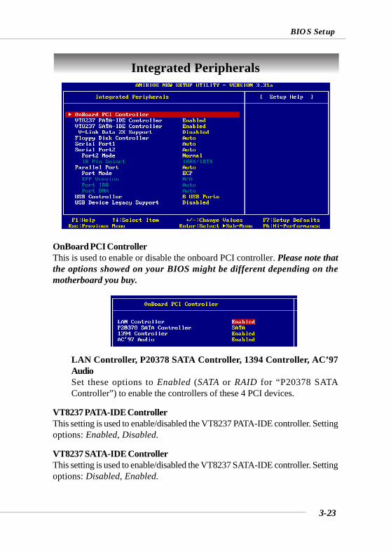
Integrated Peripherals
OnBoard PCI ControllerThis is used to enable or disable the onboard PCI controller. Please note thatthe options showed on your BIOS might be different depending on themotherboard you buy.
LAN Controller, P20378 SATA Controller, 1394 Controller, AC’97AudioSet these options to Enabled (SATA or RAID for “P20378 SATAController”) to enable the controllers of these 4 PCI devices.
VT8237 PATA-IDE ControllerThis setting is used to enable/disabled the VT8237 PATA-IDE controller. Settingoptions: Enabled, Disabled.
VT8237 SATA-IDE ControllerThis setting is used to enable/disabled the VT8237 SATA-IDE controller. Settingoptions: Disabled, Enabled.
3-24
MS-6590 ATX Mainboard
V-Link Data 2X SupportThis setting controls the onboard V-Link Data 2X Support. Setting options:Enabled, Disabled.
Floopy Disk ControllerThis is used to enable or disable the onboard Floppy controller.
Serial Port 1/2These items specify the base I/O port addresses of the onboard Serial Port 1(COM A)/Serial Port 2 (COM B). Selecting Auto allows AMIBIOS toautomatically determine the correct base I/O port address. Settings: Auto,3F8/COM1, 2F8/COM2, 3E8/COM3, 2E8/COM4 and Disabled.
Port2 ModeThis item sets the operation mode for Serial Port 2. Settings: Normal,1.6 uS, 3/16 Baud and ASKIR (the last three operation modes are settingoptions for IR function).
IR Pin SelectSet to IRRX/IRTX when using an internal IR module connected to the IRheader. Set to SINB/SOUTB. when connecting an IR adapter to COM B.
Parallel PortThis field specifies the base I/O port address of the onboard parallel port.Selecting Auto allows AMIBIOS to automatically determine the correct baseI/O port address. Settings: Auto, 378, 278, 3BC, Disabled.
Port ModeThis item selects the operation mode for the onboard parallel port: ECP,Normal, Bi-Dir or EPP.
Option DescriptionAuto BIOS will automatically determine whether to enable the
onboard Floppy controller or not.
Enabled Enables the onboard Floppy controller.
Disabled Disables the onboard Floppy controller.
3-25
BIOS Setup
EPP VersionThe item selects the EPP version used by the parallel port if the port is setto EPP mode. Settings: 1.7, 1.9.
Port IRQWhen OnBoard Parallel Port is set to Auto, the item shows Auto indicatingthat BIOS determines the IRQ for the parallel port automatically.
Port DMAThis feature needs to be configured only when Parallel Port Mode is setto the ECP mode. When Parallel Port is set to Auto, the field will showAuto indicating that BIOS automatically determines the DMA channel forthe parallel port.
USB ControllerThis setting is used to enable/disable the onboard USB ports. Setting options:Disabled, 2 USB Ports, 4 USB Ports, 6 USB Ports.
USB Device Legacy SupportSet to All Device if you need to use any USB device in the operating systemthat does not support or have any USB driver installed, such as DOS and SCOUnix. Set to No Mice only if you want to use any USB device other than theUSB mouse.
3-26
MS-6590 ATX Mainboard
PC Health Status
This section shows the status of your CPU, fan, overall system status,etc. Monitor function is available only if there is hardware monitoringmechanism onboard.
Chassis IntrusionThe field enables or disables the feature of recording the chassis intrusionstatus and issuing a warning message if the chassis is once opened. To clearthe warning message, set the field to Reset. The setting of the field willautomatically return to Enabled later. Settings: Enabled, Reset, Disabled.
CPU/System Temperature, CPU/System Fan Speed, Vcore, +5.0V, +12.0V,-12.0V, -5.0V, Battery, +5V SBThese items display the current status of all of the monitored hardware devices/components such as CPU voltages, temperatures and all fans’ speeds.
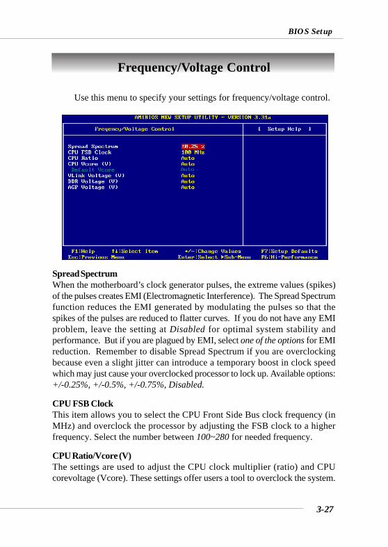
3-27
BIOS Setup
Use this menu to specify your settings for frequency/voltage control.
Spread SpectrumWhen the motherboard’s clock generator pulses, the extreme values (spikes)of the pulses creates EMI (Electromagnetic Interference). The Spread Spectrumfunction reduces the EMI generated by modulating the pulses so that thespikes of the pulses are reduced to flatter curves. If you do not have any EMIproblem, leave the setting at Disabled for optimal system stability andperformance. But if you are plagued by EMI, select one of the options for EMIreduction. Remember to disable Spread Spectrum if you are overclockingbecause even a slight jitter can introduce a temporary boost in clock speedwhich may just cause your overclocked processor to lock up. Available options:+/-0.25%, +/-0.5%, +/-0.75%, Disabled.
CPU FSB ClockThis item allows you to select the CPU Front Side Bus clock frequency (inMHz) and overclock the processor by adjusting the FSB clock to a higherfrequency. Select the number between 100~280 for needed frequency.
CPU Ratio/Vcore (V)The settings are used to adjust the CPU clock multiplier (ratio) and CPUcorevoltage (Vcore). These settings offer users a tool to overclock the system.
Frequency/Voltage Control
3-28
MS-6590 ATX Mainboard
MSI Reminds You...Changing CPU Ratio/Vcore could result in the instability of thesystem; therefore, it is NOT recommended to change the defaultsetting for long-term usage.
Default VcoreIt shows the default Vcore of the CPU, which is read-only.
VLink Voltage (V)Adjusting the VLink voltage can increase the VLink voltage for the possibleoverclocking. Setting options: Auto, 2.60, 2.70, 2.80.
DDR Voltage (V)Adjusting the DDR voltage can increase the DDR speed. Any changes madeto this setting may cause a stability issue, so changing the DDR voltage forlong-term purpose is NOT recommended. Setting options: Auto, 2.55, 2.60, 2.65, 2.70, 2.75, 2.80, 2.85, 2.90, 2.95, 3.00, 3.05, 3.10, 3.20, 3.25, 3.30.
AGP Voltage (V)AGP voltage is adjustable in the field, allowing you to increase the performanceof your AGP display card when overclocking, but the stability may be affected.Setting options: Auto, 1.55 to 2.10 at 0.05 increment.
MSI Reminds You...The settings shown in different color in CPU Vcore (V), VLinkVoltage (V), DDR Voltage (V) and AGP Voltage (V) helps toverify if your setting is proper for your system.White: Safe setting.Yellow: High performance setting.Red: Not recommended setting and the system may be unstable.
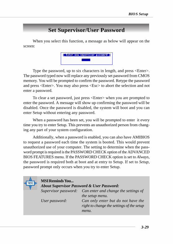
3-29
BIOS Setup
Set Supervisor/User Password
When you select this function, a message as below will appear on thescreen:
Type the password, up to six characters in length, and press <Enter>.The password typed now will replace any previously set password from CMOSmemory. You will be prompted to confirm the password. Retype the passwordand press <Enter>. You may also press <Esc> to abort the selection and notenter a password.
To clear a set password, just press <Enter> when you are prompted toenter the password. A message will show up confirming the password will bedisabled. Once the password is disabled, the system will boot and you canenter Setup without entering any password.
When a password has been set, you will be prompted to enter it everytime you try to enter Setup. This prevents an unauthorized person from chang-ing any part of your system configuration.
Additionally, when a password is enabled, you can also have AMIBIOSto request a password each time the system is booted. This would preventunauthorized use of your computer. The setting to determine when the pass-word prompt is required is the PASSWORD CHECK option of the ADVANCEDBIOS FEATURES menu. If the PASSWORD CHECK option is set to Always,the password is required both at boot and at entry to Setup. If set to Setup,password prompt only occurs when you try to enter Setup.
MSI Reminds You...About Supervisor Password & User Password:Supervisor password: Can enter and change the settings of
the setup menu.User password: Can only enter but do not have the
right to change the settings of the setupmenu.

3-30
MS-6590 ATX Mainboard
Load High Performance/BIOS Setup DefaultsThe two options on the main menu allow users to restore all of the BIOS
settings to High Performance defaults or BIOS Setup defaults. The High Per-formance Defaults are the values set by the mainboard manufacturer for thebest system performance but probably will cause a stability issue. The BIOSSetup Defaults are the default values also set by the mainboard manufacturerfor stable performance of the mainboard.
When you select Load High Performance Defaults, a message as belowappears:
Pressing ‘Enter’ loads the default BIOS values that enable the best sys-tem performance but may lead to a stability issue.
When you select Load BIOS Setup Defaults, a message as below appears:
Pressing ‘Enter’ loads the default values that are factory settings forstable system performance.
MSI Reminds You...The option is for power or overclocking users only. Use of highperformance defaults will tighten most timings to increase thesystem performance. Therefore, a high-end system configurationis a must, which means you need high-quality VGA adapter,RAM and so on. We don’t recommend that users should applythe high performance defaults in their regular systems.Otherwise, the system may become unstable or even crash. If thesystem crashes or hangs after enabling the feature, please CLEARCMOS DATA to resolve the problem. For more information, referto “Clear CMOS Jumper:JBAT1” in Chapter 2.
Using 2-, 4- or 6-Channel Audio Function
A-1
Appendix. Using 4- or 6-ChannelAudio FunctionAppendix: Using 2-, 4- or 6-Channel AudioFunction
The motherboard comes with C-Media 9739A AC’97 audio chip, whichprovides exclusive Xear 3DTM technology, a value-add PC audio total solution.In addition, C-Media designs a Universal Driver Architecture (UDA driver)which has a flexible interface so that it can be applied to different platforms andall C-Media audio chips. C-Media 9739A allows the board to attach 4 or 6speakers for better surround sound effect. The section will tell you how toinstall and use 2-/4-/6-channel audio function on the board.
A-2
MS-6590 ATX Mainboard
The mainboard is able to transform the audio connectors on the back panelfrom 2-channel to 4-/6-channel. To use the function, you need to install the C-Media UDA driver.
The UDA driver supports all Windows, C-Media AC’97 CODEC, and audiocontrollers (south bridges) on board. Moreover, there is no operation barrierwhen switching to other C-Media’s products.
Main Features of UDA Driver V.029:1. Xear 3D - 5.1 Virtual SPEAKER SHIFTER:
It allows users to enjoy multi-channel surround sound system with anykind of appliances including earphone (we call it 5.1 Xearphone feature), 2,2.1 to 5.1 speakers.
It has an user-friendly interface to shifting virtual speakers just likemoving the physical speakers literally to break through any spatial placementlimitation.
Users can adjust the best field dynamically adapted to different appliancesand sound sources.
A new multi-channel listening mode is provided: Earphone plus. You canuse open-aired earphones in place of rear speakers to save the cost andsetup trouble of rear speakers.
2. HRTF 3D Positional Audio : Xear 3D integrated world-standard Sensaura’sCRL3DTM engine for providing the best HRTF (Head-Related TransferFunction) 3D positional audio and related features as follows. They arenecessary for gaming and interactive applications:
EAXTM 1.0 & 2.0 (Creative Environment Audio eXtension has been aworld-wide standard for high-quality games.)
A3DTM 1.0 Compatible with Microsoft DirectSound 3DTM H/W & S/W
3. Sound Effects - Environment: It provides 27 options for simulating thelistening environment and get more magic and different sound field.
4. Sound Effects - Environment Size: It provides Small, Medium and Largespace for every type of Environment.
5. Sound Effects - Equalizer: It offers 10-band Equalizer and 12 pre-set modelslike “Live”, “Jazz” and so on for users to modify the frequency response ofsound signals. There is also “User Defined” list for users to save their own
Installing C-Media Drivers
Using 2-, 4- or 6-Channel Audio Function
A-3
settings.6. Demo Program - Play3D Demo: It provides 5 sound sources and moving
path for playing for 3D audio playing. You can feel 3D positional sound andalso use this program to adjust your virtual speakers before playing 3Daudio applications like gaming.
7. Demo Program - Multi-channel Music: Multi-channel Music DemoProgram has three 5.1-channel melodies for playing. You can also click onthe speakers respectively to test each channel and adjust virtual speakersbefore playing multi-channel audio applications like DVD.
To install C-Media drivers:1. Insert the companion CD into the CD-ROM drive. The setup screen will
automatically appear.2. Click on C-Media Sound Drivers.3. Follow the on-screen instructions to complete installation.4. Restart the system.
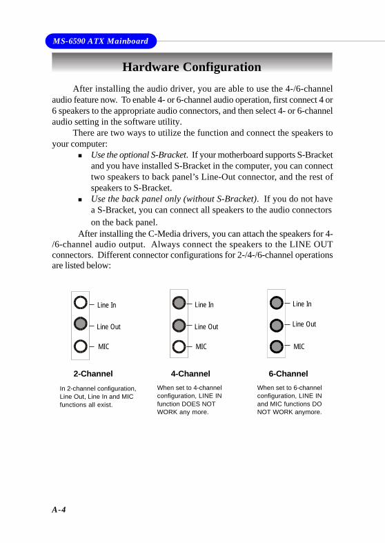
A-4
MS-6590 ATX Mainboard
After installing the audio driver, you are able to use the 4-/6-channelaudio feature now. To enable 4- or 6-channel audio operation, first connect 4 or6 speakers to the appropriate audio connectors, and then select 4- or 6-channelaudio setting in the software utility.
There are two ways to utilize the function and connect the speakers toyour computer:
Use the optional S-Bracket. If your motherboard supports S-Bracketand you have installed S-Bracket in the computer, you can connecttwo speakers to back panel’s Line-Out connector, and the rest ofspeakers to S-Bracket.Use the back panel only (without S-Bracket). If you do not havea S-Bracket, you can connect all speakers to the audio connectorson the back panel.
After installing the C-Media drivers, you can attach the speakers for 4-/6-channel audio output. Always connect the speakers to the LINE OUTconnectors. Different connector configurations for 2-/4-/6-channel operationsare listed below:
Hardware Configuration
2-ChannelIn 2-channel configuration,Line Out, Line In and MICfunctions all exist.
4-Channel 6-ChannelWhen set to 4-channelconfiguration, LINE INfunction DOES NOTWORK any more.
When set to 6-channelconfiguration, LINE INand MIC functions DONOT WORK anymore.
MIC
Line In
Line Out
MIC
Line Out
Line In
MIC
Line Out
Line In
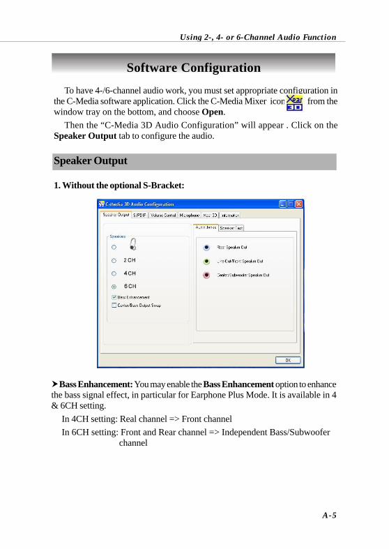
Using 2-, 4- or 6-Channel Audio Function
A-5
To have 4-/6-channel audio work, you must set appropriate configuration inthe C-Media software application. Click the C-Media Mixer icon from thewindow tray on the bottom, and choose Open.
Then the “C-Media 3D Audio Configuration” will appear . Click on theSpeaker Output tab to configure the audio.
Speaker Output
1. Without the optional S-Bracket:
Software Configuration
Bass Enhancement: You may enable the Bass Enhancement option to enhancethe bass signal effect, in particular for Earphone Plus Mode. It is available in 4& 6CH setting.
In 4CH setting: Real channel => Front channelIn 6CH setting: Front and Rear channel => Independent Bass/Subwoofer
channel
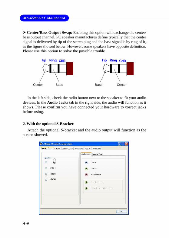
A-6
MS-6590 ATX Mainboard
2. With the optional S-Bracket:Attach the optional S-bracket and the audio output will function as the
screen showed.
Center/Bass Output Swap: Enabling this option will exchange the center/bass output channel. PC speaker manufactures define typically that the centersignal is delivered by tip of the stereo plug and the bass signal is by ring of it,as the figure showed below. However, some speakers have opposite definition.Please use this option to solve the possible trouble.
In the left side, check the radio button next to the speaker to fit your audiodevices. In the Audio Jacks tab in the right side, the audio will function as itshows. Please confirm you have connected your hardware to correct jacksbefore using.
CenterBassCenter Bass
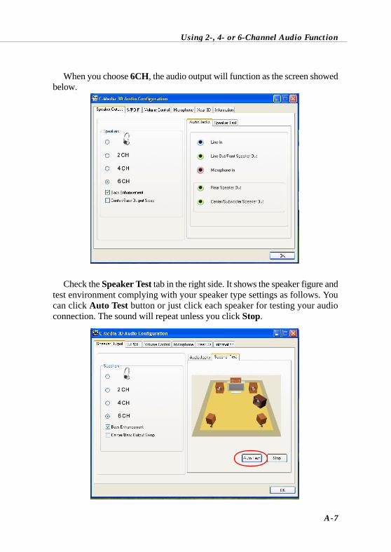
Using 2-, 4- or 6-Channel Audio Function
A-7
When you choose 6CH, the audio output will function as the screen showedbelow.
Check the Speaker Test tab in the right side. It shows the speaker figure andtest environment complying with your speaker type settings as follows. Youcan click Auto Test button or just click each speaker for testing your audioconnection. The sound will repeat unless you click Stop.
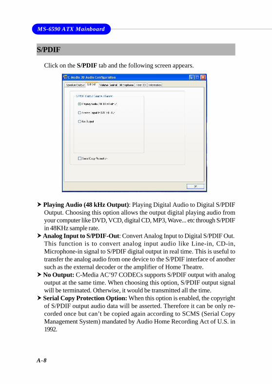
A-8
MS-6590 ATX Mainboard
S/PDIF
Click on the S/PDIF tab and the following screen appears.
Playing Audio (48 kHz Output): Playing Digital Audio to Digital S/PDIFOutput. Choosing this option allows the output digital playing audio fromyour computer like DVD, VCD, digital CD, MP3, Wave... etc through S/PDIFin 48KHz sample rate.
Analog Input to S/PDIF-Out: Convert Analog Input to Digital S/PDIF Out.This function is to convert analog input audio like Line-in, CD-in,Microphone-in signal to S/PDIF digital output in real time. This is useful totransfer the analog audio from one device to the S/PDIF interface of anothersuch as the external decoder or the amplifier of Home Theatre.
No Output: C-Media AC’97 CODECs supports S/PDIF output with analogoutput at the same time. When choosing this option, S/PDIF output signalwill be terminated. Otherwise, it would be transmitted all the time.
Serial Copy Protection Option: When this option is enabled, the copyrightof S/PDIF output audio data will be asserted. Therefore it can be only re-corded once but can’t be copied again according to SCMS (Serial CopyManagement System) mandated by Audio Home Recording Act of U.S. in1992.
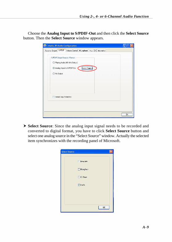
Using 2-, 4- or 6-Channel Audio Function
A-9
Select Source: Since the analog input signal needs to be recorded andconverted to digital format, you have to click Select Source button andselect one analog source in the “Select Source” window. Actually the selecteditem synchronizes with the recording panel of Microsoft.
Choose the Analog Input to S/PDIF-Out and then click the Select Sourcebutton. Then the Select Source window appears.
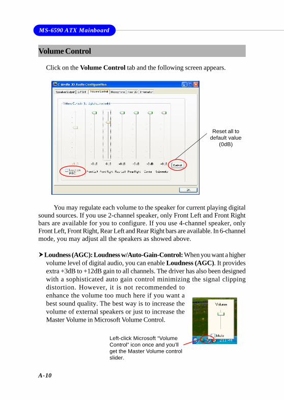
A-10
MS-6590 ATX Mainboard
You may regulate each volume to the speaker for current playing digitalsound sources. If you use 2-channel speaker, only Front Left and Front Rightbars are available for you to configure. If you use 4-channel speaker, onlyFront Left, Front Right, Rear Left and Rear Right bars are available. In 6-channelmode, you may adjust all the speakers as showed above.
Loudness (AGC): Loudness w/Auto-Gain-Control: When you want a highervolume level of digital audio, you can enable Loudness (AGC). It providesextra +3dB to +12dB gain to all channels. The driver has also been designedwith a sophisticated auto gain control minimizing the signal clippingdistortion. However, it is not recommended toenhance the volume too much here if you want abest sound quality. The best way is to increase thevolume of external speakers or just to increase theMaster Volume in Microsoft Volume Control.
Volume Control
Click on the Volume Control tab and the following screen appears.
Reset all todefault value
(0dB)
Left-click Microsoft “VolumeControl” icon once and you’llget the Master Volume controlslider.
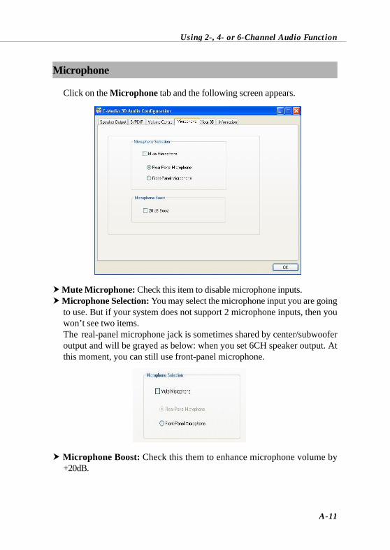
Using 2-, 4- or 6-Channel Audio Function
A-11
Microphone
Click on the Microphone tab and the following screen appears.
Mute Microphone: Check this item to disable microphone inputs. Microphone Selection: You may select the microphone input you are goingto use. But if your system does not support 2 microphone inputs, then youwon’t see two items.The real-panel microphone jack is sometimes shared by center/subwooferoutput and will be grayed as below: when you set 6CH speaker output. Atthis moment, you can still use front-panel microphone.
Microphone Boost: Check this them to enhance microphone volume by+20dB.
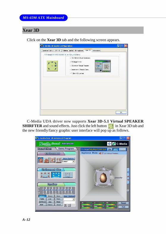
A-12
MS-6590 ATX Mainboard
Xear 3D
Click on the Xear 3D tab and the following screen appears.
C-Media UDA driver now supports Xear 3D-5.1 Virtual SPEAKERSHIRFTER and sound effects. Just click the left button in Xear 3D tab andthe new friendly/fancy graphic user interface will pop up as follows.
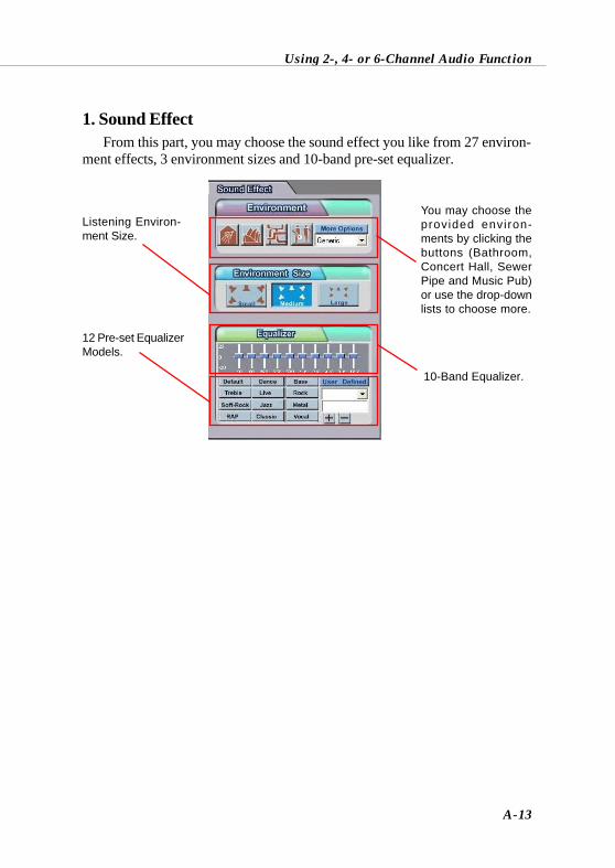
Using 2-, 4- or 6-Channel Audio Function
A-13
From this part, you may choose the sound effect you like from 27 environ-ment effects, 3 environment sizes and 10-band pre-set equalizer.
1. Sound Effect
You may choose theprovided environ-ments by clicking thebuttons (Bathroom,Concert Hall, SewerPipe and Music Pub)or use the drop-downlists to choose more.
Listening Environ-ment Size.
10-Band Equalizer.
12 Pre-set EqualizerModels.
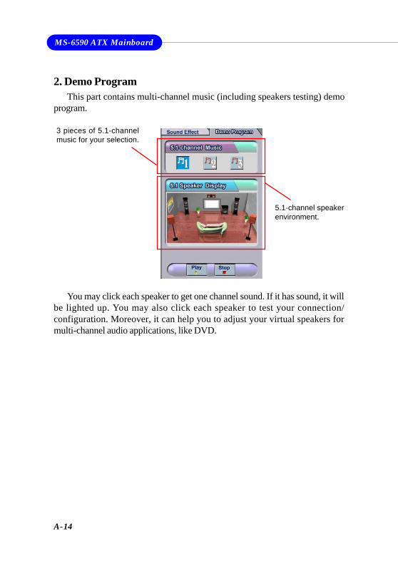
A-14
MS-6590 ATX Mainboard
You may click each speaker to get one channel sound. If it has sound, it willbe lighted up. You may also click each speaker to test your connection/configuration. Moreover, it can help you to adjust your virtual speakers formulti-channel audio applications, like DVD.
2. Demo ProgramThis part contains multi-channel music (including speakers testing) demo
program.
3 pieces of 5.1-channelmusic for your selection.
5.1-channel speakerenvironment.
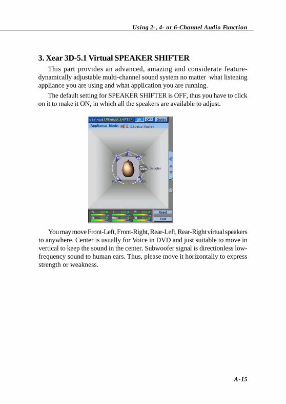
Using 2-, 4- or 6-Channel Audio Function
A-15
3. Xear 3D-5.1 Virtual SPEAKER SHIFTERThis part provides an advanced, amazing and considerate feature-
dynamically adjustable multi-channel sound system no matter what listeningappliance you are using and what application you are running.
The default setting for SPEAKER SHIFTER is OFF, thus you have to clickon it to make it ON, in which all the speakers are available to adjust.
You may move Front-Left, Front-Right, Rear-Left, Rear-Right virtual speakersto anywhere. Center is usually for Voice in DVD and just suitable to move invertical to keep the sound in the center. Subwoofer signal is directionless low-frequency sound to human ears. Thus, please move it horizontally to expressstrength or weakness.
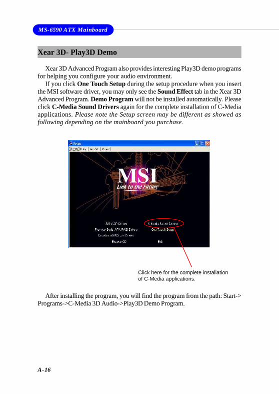
A-16
MS-6590 ATX Mainboard
Xear 3D- Play3D Demo
Xear 3D Advanced Program also provides interesting Play3D demo programsfor helping you configure your audio environment.
If you click One Touch Setup during the setup procedure when you insertthe MSI software driver, you may only see the Sound Effect tab in the Xear 3DAdvanced Program. Demo Program will not be installed automatically. Pleaseclick C-Media Sound Drivers again for the complete installation of C-Mediaapplications. Please note the Setup screen may be different as showed asfollowing depending on the mainboard you purchase.
Click here for the complete installationof C-Media applications.
After installing the program, you will find the program from the path: Start->Programs->C-Media 3D Audio->Play3D Demo Program.
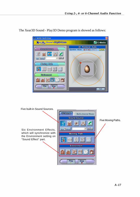
Using 2-, 4- or 6-Channel Audio Function
A-17
The Xear3D Sound - Play3D Demo program is showed as follows:
Five built-in Sound Sources.
Six Environment Effects,which will synchronize withthe Environment setting on“Sound Effect” part.
Five Moving Paths.
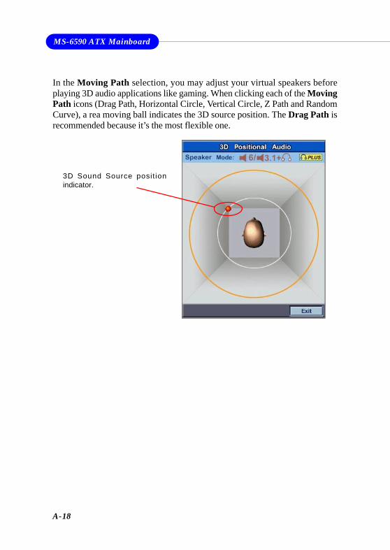
A-18
MS-6590 ATX Mainboard
In the Moving Path selection, you may adjust your virtual speakers beforeplaying 3D audio applications like gaming. When clicking each of the MovingPath icons (Drag Path, Horizontal Circle, Vertical Circle, Z Path and RandomCurve), a rea moving ball indicates the 3D source position. The Drag Path isrecommended because it’s the most flexible one.
3D Sound Source positionindicator.
Using 2-, 4- or 6-Channel Audio Function
A-19
Attaching SpeakersTo perform multichannel audio operation, connect multiple speakers to
the system. You should connect the same number of speakers as the audiochannels you will select in the software utility.
Using S-BRACKET connectors:
S-Bracket is an optional accessory. It gives access to analog and digitalaudio output by integrating both SPDIF (Sony & Philips Digital Interface) andanalog LINE OUT connectors. To use the S-Bracket, you should select correctsetting in the software utility. For information about the setting, refer to Se-lecting 2-, 4- or 6-Channel Setting later in the section.
Connector configurations for 2-, 4- and 6-channel using S-Bracket aredescribed below:
Using 2-, 4- or 6-Channel Audio Function
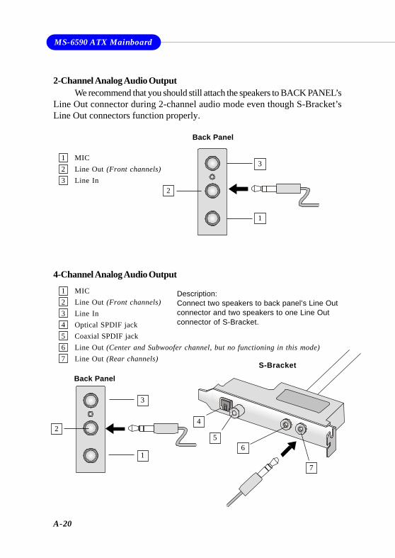
A-20
MS-6590 ATX Mainboard
4-Channel Analog Audio Output
Description:Connect two speakers to back panel’s Line Outconnector and two speakers to one Line Outconnector of S-Bracket.
2-Channel Analog Audio OutputWe recommend that you should still attach the speakers to BACK PANEL’s
Line Out connector during 2-channel audio mode even though S-Bracket’sLine Out connectors function properly.
1 MIC2 Line Out (Front channels)3 Line In4 Optical SPDIF jack5 Coaxial SPDIF jack6 Line Out (Center and Subwoofer channel, but no functioning in this mode)7 Line Out (Rear channels)
1 MIC2 Line Out (Front channels)3 Line In
1
2
3
Back Panel
Back Panel
1
2
3
6
7
4
5
S-Bracket
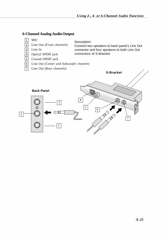
Using 2-, 4- or 6-Channel Audio Function
A-21
6-Channel Analog Audio Output
Description:Connect two speakers to back panel’s Line Outconnector and four speakers to both Line Outconnectors of S-Bracket.
1 MIC2 Line Out (Front channels)3 Line In4 Optical SPDIF jack5 Coaxial SPDIF jack6 Line Out (Center and Subwoofer channel)7 Line Out (Rear channels)
S-Bracket
1
2
3
Back Panel
6
7
4
5
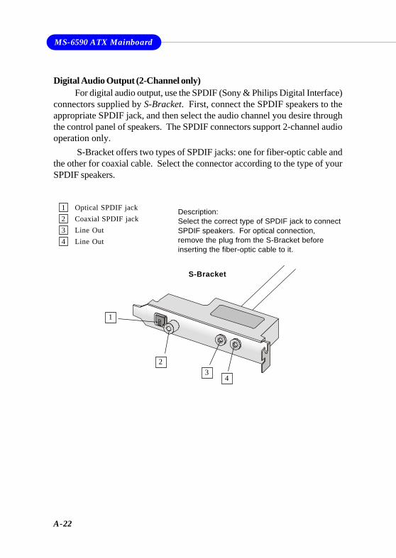
A-22
MS-6590 ATX Mainboard
1 Optical SPDIF jack2 Coaxial SPDIF jack3 Line Out4 Line Out
Description:Select the correct type of SPDIF jack to connectSPDIF speakers. For optical connection,remove the plug from the S-Bracket beforeinserting the fiber-optic cable to it.
Digital Audio Output (2-Channel only)For digital audio output, use the SPDIF (Sony & Philips Digital Interface)
connectors supplied by S-Bracket. First, connect the SPDIF speakers to theappropriate SPDIF jack, and then select the audio channel you desire throughthe control panel of speakers. The SPDIF connectors support 2-channel audiooperation only.
S-Bracket offers two types of SPDIF jacks: one for fiber-optic cable andthe other for coaxial cable. Select the connector according to the type of yourSPDIF speakers.
S-Bracket
1
23
4
VIA VT8237 Serial ATA RAID Introduction
B-1
Appendix. Using 4- or 6-ChannelAudio FunctionAppendix B: VIA VT8237 Serial ATA
RAID IntroductionThe Southbridge VT8237 provides a hybrid solution that combines two
independent SATA ports for support of up to two Serial ATA (Serial ATARAID) drives.
Serial ATA (SATA) is the latest generation of the ATA interface. SATAhard drives deliver blistering transfer speeds of up to 150MB/sec. Serial ATAuses long, thin cables, making it easier to connect your drive and improvingthe airflow inside your PC.
The key features of VT8237 SATA RAID are:1. Support two SATA + two PATA hard disk drives.2. Only SATA supports RAID.3. Supports ATA 133 high performance hard disk drive.4. Dual independent ATA channels and maximum connection of four
hard disk drives allowed.5. Supports Ultra DMA mode 6/5/4/3/2/1/0, DMA mode 2/1/0, and PIO
mode 4/3/2/1/0.6. Supports RAID 0 and RAID 1.7. 4 KB to 64 KB striping block size support.8. Bootable disk or disk array support.9. Windows-based RAID configure and management software tool.
(Compatible with BIOS)10. Supports hot-swap failed disk drive in RAID 1 array.11. ATA SMART function support.12. Microsoft Windows 98, Me, NT4.0, 2000, XP operating systems
support.13. Event log for easy troubleshooting.
MS-6590 ATX Mainboard
B-2
IntroductionThis section gives a brief introduction on the RAID-related background
knowledge and a brief introduction on VIA SATA RAID Host Controller. Forusers wishing to install their VIA SATA RAID driver and RAID software,proceed to Driver and RAID Software Installation section.
RAID Basics
RAID (Redundant Array of Independent Disks) is a method of combiningtwo or more hard disk drives into one logical unit. The advantage of an Arrayis to provide better performance or data fault tolerance. Fault tolerance isachieved through data redundant operation, where if one drives fails, a mirroredcopy of the data can be found on another drive. This can prevent data loss ifthe operating system fails or hangs. The individual disk drives in an array arecalled “members”. The configuration information of each member is recordedin the “reserved sector” that identifies the drive as a member. All disk membersin a formed disk array are recognized as a single physical drive to the operatingsystem.
Hard disk drives can be combined together through a few differentmethods. The different methods are referred to as different RAID levels.Different RAID levels represent different performance levels, security levelsand implementation costs. The RAID levels which the VIA VT8237 SATARAID Host Controller supports are RAID 0 and RAID 1. The table belowbriefly introduced these RAID levels.
RAID Level No. of Drives Capacity Benefits
RAID 0
(Striping)
2 Number drives * 2 Highest performance without data
protection
RAID 1
(Mirroring)
2 Smallest size Data protection
VIA VT8237 Serial ATA RAID Introduction
B-3
RAID 0 (Striping)RAID 0 reads and writes sectors of data interleaved between multiple
drives. If any disk member fails, it affects the entire array. The disk array datacapacity is equal to the number of drive members times the capacity of thesmallest member. The striping block size can be set from 4KB to 64KB. RAID0 does not support fault tolerance.
RAID 1 (Mirroring)RAID 1 writes duplicate data onto a pair of drives and reads both sets of
data in parallel. If one of the mirrored drives suffers a mechanical failure ordoes not respond, the remaining drive will continue to function. Due toredundancy, the drive capacity of the array is the capacity of the smallestdrive. Under a RAID 1 setup, an extra drive called the .spare drive. can beattached. Such a drive will be activated to replace a failed drive that is part ofa mirrored array. Due to the fault tolerance, if any RAID 1 drive fails, dataaccess will not be affected as long as there are other working drives in thearray.
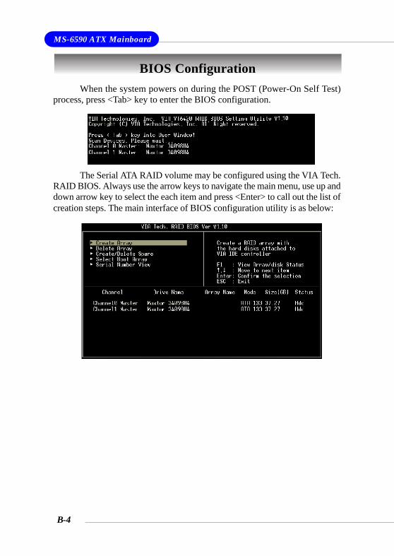
MS-6590 ATX Mainboard
B-4
BIOS ConfigurationWhen the system powers on during the POST (Power-On Self Test)
process, press <Tab> key to enter the BIOS configuration.
The Serial ATA RAID volume may be configured using the VIA Tech.RAID BIOS. Always use the arrow keys to navigate the main menu, use up anddown arrow key to select the each item and press <Enter> to call out the list ofcreation steps. The main interface of BIOS configuration utility is as below:
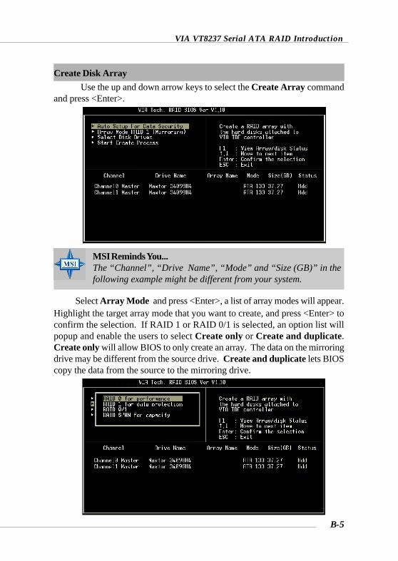
VIA VT8237 Serial ATA RAID Introduction
B-5
Create Disk ArrayUse the up and down arrow keys to select the Create Array command
and press <Enter>.
MSI Reminds You...The “Channel”, “Drive Name”, “Mode” and “Size (GB)” in thefollowing example might be different from your system.
Select Array Mode and press <Enter>, a list of array modes will appear.Highlight the target array mode that you want to create, and press <Enter> toconfirm the selection. If RAID 1 or RAID 0/1 is selected, an option list willpopup and enable the users to select Create only or Create and duplicate.Create only will allow BIOS to only create an array. The data on the mirroringdrive may be different from the source drive. Create and duplicate lets BIOScopy the data from the source to the mirroring drive.
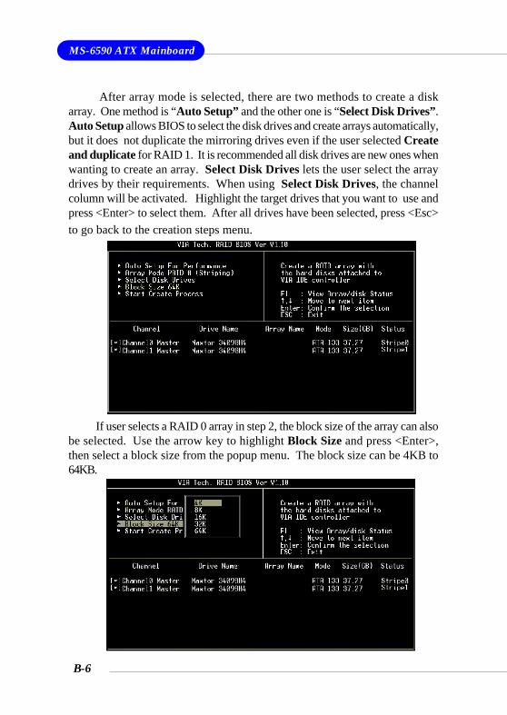
MS-6590 ATX Mainboard
B-6
If user selects a RAID 0 array in step 2, the block size of the array can alsobe selected. Use the arrow key to highlight Block Size and press <Enter>,then select a block size from the popup menu. The block size can be 4KB to64KB.
After array mode is selected, there are two methods to create a diskarray. One method is “Auto Setup” and the other one is “Select Disk Drives”.Auto Setup allows BIOS to select the disk drives and create arrays automatically,but it does not duplicate the mirroring drives even if the user selected Createand duplicate for RAID 1. It is recommended all disk drives are new ones whenwanting to create an array. Select Disk Drives lets the user select the arraydrives by their requirements. When using Select Disk Drives, the channelcolumn will be activated. Highlight the target drives that you want to use andpress <Enter> to select them. After all drives have been selected, press <Esc>to go back to the creation steps menu.

VIA VT8237 Serial ATA RAID Introduction
B-7
Use the arrow key to highlight Start Create Process and press <Enter>.A warning message will appear, Press Y to finish the creation, or press N tocancel the creation.
Important note: All existing content in the hard drive will be destroyedafter array creation.
MSI Reminds You...Even though 64KB is the recommended setting for most users, youshould choose the block size value which is best suited to yourspecific RAID usage model.4KB: For specialized usage models requiring 4KB blocks8KB: For specialized usage models requiring 8KB blocks16KB: Best for sequential transfers32KB: Good for sequential transfers64KB: Optimal setting
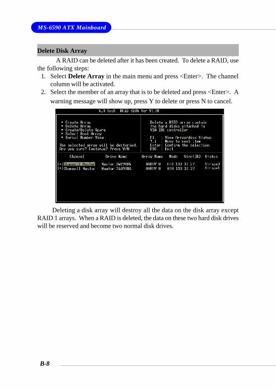
MS-6590 ATX Mainboard
B-8
Delete Disk ArrayA RAID can be deleted after it has been created. To delete a RAID, use
the following steps:1. Select Delete Array in the main menu and press <Enter>. The channel
column will be activated.2. Select the member of an array that is to be deleted and press <Enter>. A
warning message will show up, press Y to delete or press N to cancel.
Deleting a disk array will destroy all the data on the disk array exceptRAID 1 arrays. When a RAID is deleted, the data on these two hard disk driveswill be reserved and become two normal disk drives.
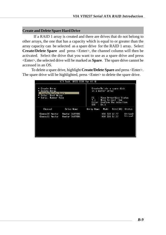
VIA VT8237 Serial ATA RAID Introduction
B-9
Create and Delete Spare Hard DriveIf a RAID 1 array is created and there are drives that do not belong to
other arrays, the one that has a capacity which is equal to or greater than thearray capacity can be selected as a spare drive for the RAID 1 array. SelectCreate/Delete Spare and press <Enter>, the channel column will then beactivated. Select the drive that you want to use as a spare drive and press<Enter>, the selected drive will be marked as Spare. The spare drive cannot beaccessed in an OS.
To delete a spare drive, highlight Create/Delete Spare and press <Enter>.The spare drive will be highlighted, press <Enter> to delete the spare drive.
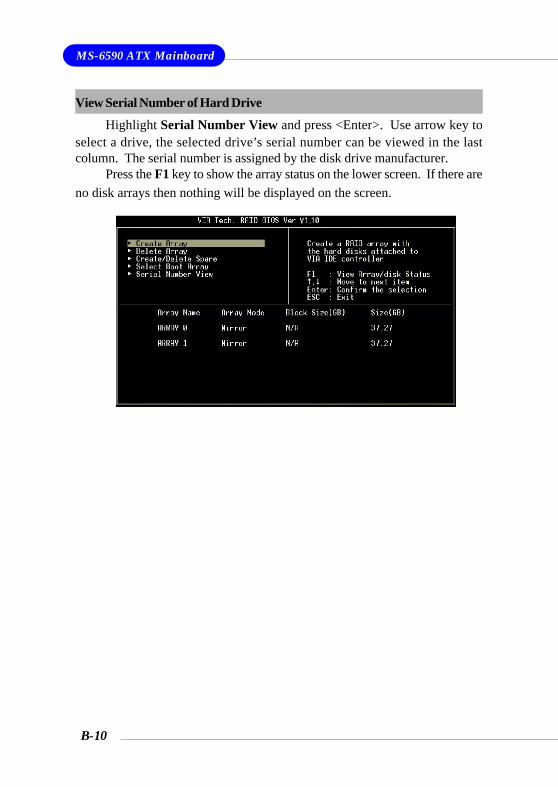
MS-6590 ATX Mainboard
B-10
View Serial Number of Hard Drive
Highlight Serial Number View and press <Enter>. Use arrow key toselect a drive, the selected drive’s serial number can be viewed in the lastcolumn. The serial number is assigned by the disk drive manufacturer.
Press the F1 key to show the array status on the lower screen. If there areno disk arrays then nothing will be displayed on the screen.
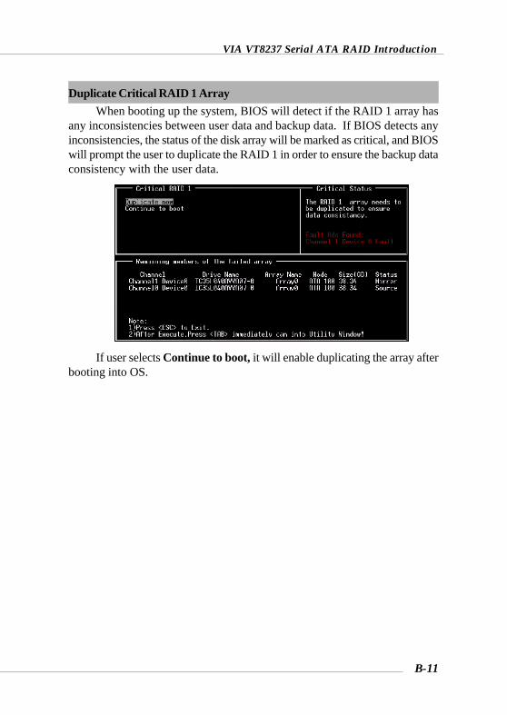
VIA VT8237 Serial ATA RAID Introduction
B-11
Duplicate Critical RAID 1 ArrayWhen booting up the system, BIOS will detect if the RAID 1 array has
any inconsistencies between user data and backup data. If BIOS detects anyinconsistencies, the status of the disk array will be marked as critical, and BIOSwill prompt the user to duplicate the RAID 1 in order to ensure the backup dataconsistency with the user data.
If user selects Continue to boot, it will enable duplicating the array afterbooting into OS.
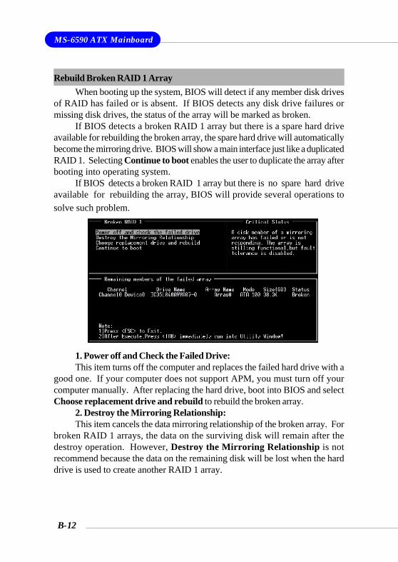
MS-6590 ATX Mainboard
B-12
Rebuild Broken RAID 1 ArrayWhen booting up the system, BIOS will detect if any member disk drives
of RAID has failed or is absent. If BIOS detects any disk drive failures ormissing disk drives, the status of the array will be marked as broken.
If BIOS detects a broken RAID 1 array but there is a spare hard driveavailable for rebuilding the broken array, the spare hard drive will automaticallybecome the mirroring drive. BIOS will show a main interface just like a duplicatedRAID 1. Selecting Continue to boot enables the user to duplicate the array afterbooting into operating system.
If BIOS detects a broken RAID 1 array but there is no spare hard driveavailable for rebuilding the array, BIOS will provide several operations tosolve such problem.
1. Power off and Check the Failed Drive:This item turns off the computer and replaces the failed hard drive with a
good one. If your computer does not support APM, you must turn off yourcomputer manually. After replacing the hard drive, boot into BIOS and selectChoose replacement drive and rebuild to rebuild the broken array.
2. Destroy the Mirroring Relationship:This item cancels the data mirroring relationship of the broken array. For
broken RAID 1 arrays, the data on the surviving disk will remain after thedestroy operation. However, Destroy the Mirroring Relationship is notrecommend because the data on the remaining disk will be lost when the harddrive is used to create another RAID 1 array.
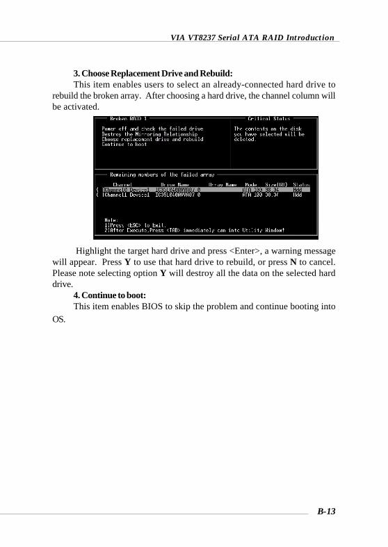
VIA VT8237 Serial ATA RAID Introduction
B-13
3. Choose Replacement Drive and Rebuild:This item enables users to select an already-connected hard drive to
rebuild the broken array. After choosing a hard drive, the channel column willbe activated.
Highlight the target hard drive and press <Enter>, a warning messagewill appear. Press Y to use that hard drive to rebuild, or press N to cancel.Please note selecting option Y will destroy all the data on the selected harddrive.
4. Continue to boot:This item enables BIOS to skip the problem and continue booting into
OS.
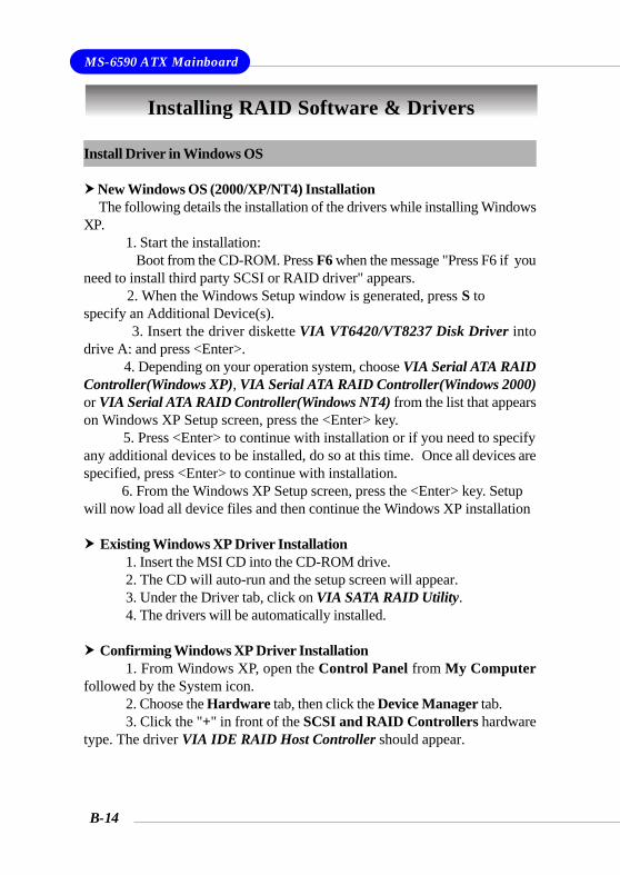
MS-6590 ATX Mainboard
B-14
Install Driver in Windows OS
New Windows OS (2000/XP/NT4) Installation The following details the installation of the drivers while installing WindowsXP.
1. Start the installation: Boot from the CD-ROM. Press F6 when the message "Press F6 if youneed to install third party SCSI or RAID driver" appears. 2. When the Windows Setup window is generated, press S tospecify an Additional Device(s). 3. Insert the driver diskette VIA VT6420/VT8237 Disk Driver intodrive A: and press <Enter>. 4. Depending on your operation system, choose VIA Serial ATA RAIDController(Windows XP), VIA Serial ATA RAID Controller(Windows 2000)or VIA Serial ATA RAID Controller(Windows NT4) from the list that appearson Windows XP Setup screen, press the <Enter> key. 5. Press <Enter> to continue with installation or if you need to specifyany additional devices to be installed, do so at this time. Once all devices arespecified, press <Enter> to continue with installation. 6. From the Windows XP Setup screen, press the <Enter> key. Setupwill now load all device files and then continue the Windows XP installation
Existing Windows XP Driver Installation1. Insert the MSI CD into the CD-ROM drive.2. The CD will auto-run and the setup screen will appear.3. Under the Driver tab, click on VIA SATA RAID Utility.4. The drivers will be automatically installed.
Confirming Windows XP Driver Installation1. From Windows XP, open the Control Panel from My Computer
followed by the System icon.2. Choose the Hardware tab, then click the Device Manager tab.3. Click the "+" in front of the SCSI and RAID Controllers hardware
type. The driver VIA IDE RAID Host Controller should appear.
Installing RAID Software & Drivers
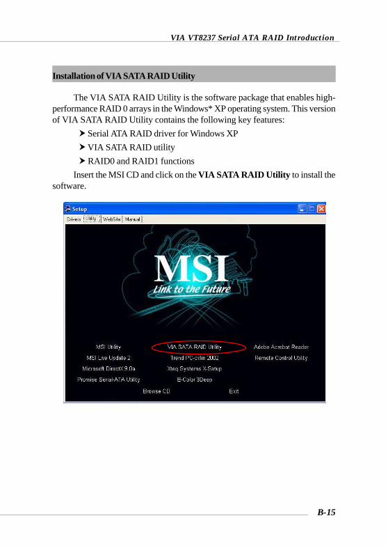
VIA VT8237 Serial ATA RAID Introduction
B-15
Installation of VIA SATA RAID Utility
The VIA SATA RAID Utility is the software package that enables high-performance RAID 0 arrays in the Windows* XP operating system. This versionof VIA SATA RAID Utility contains the following key features:
Serial ATA RAID driver for Windows XP VIA SATA RAID utility RAID0 and RAID1 functions
Insert the MSI CD and click on the VIA SATA RAID Utility to install thesoftware.
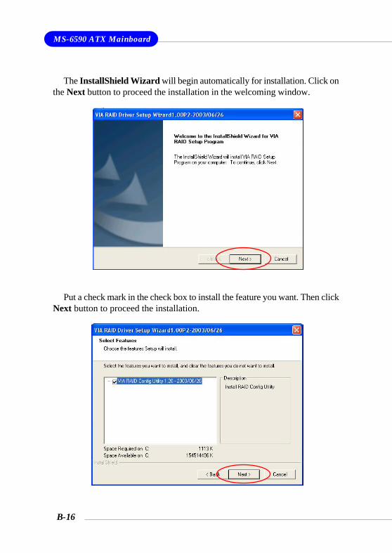
MS-6590 ATX Mainboard
B-16
The InstallShield Wizard will begin automatically for installation. Click onthe Next button to proceed the installation in the welcoming window.
Put a check mark in the check box to install the feature you want. Then clickNext button to proceed the installation.
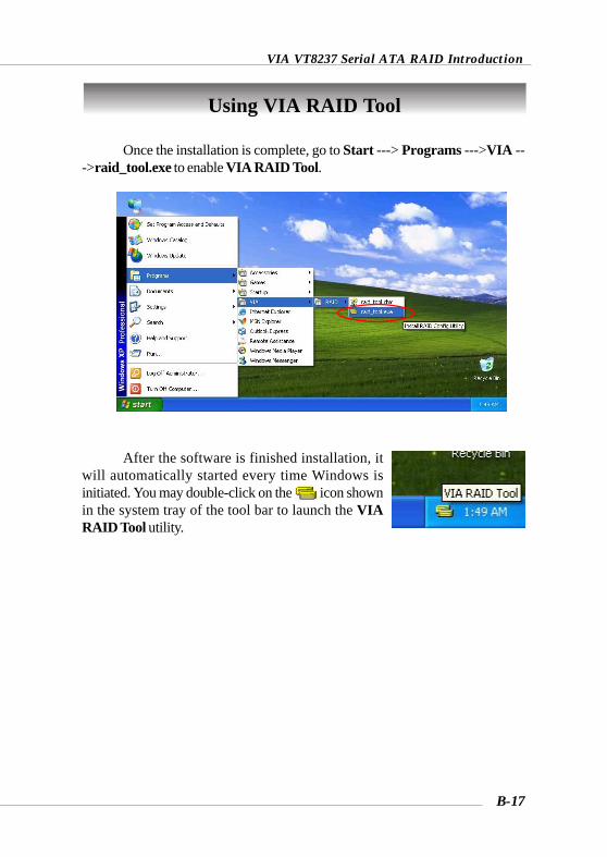
VIA VT8237 Serial ATA RAID Introduction
B-17
Once the installation is complete, go to Start ---> Programs --->VIA --->raid_tool.exe to enable VIA RAID Tool.
After the software is finished installation, itwill automatically started every time Windows isinitiated. You may double-click on the icon shownin the system tray of the tool bar to launch the VIARAID Tool utility.
Using VIA RAID Tool
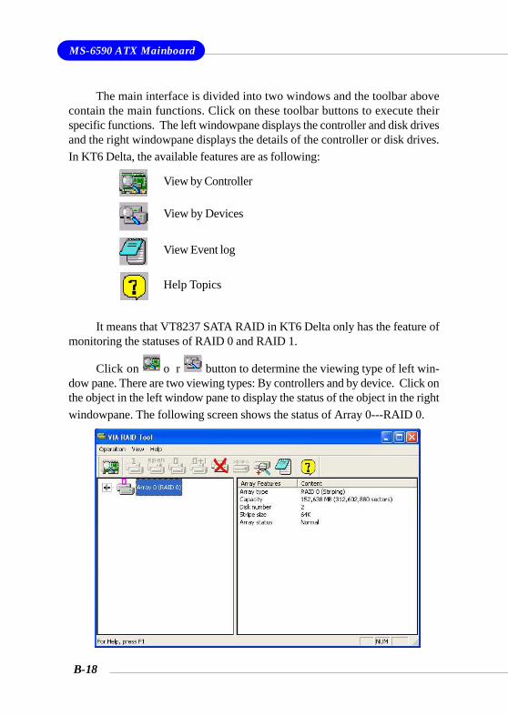
MS-6590 ATX Mainboard
B-18
The main interface is divided into two windows and the toolbar abovecontain the main functions. Click on these toolbar buttons to execute theirspecific functions. The left windowpane displays the controller and disk drivesand the right windowpane displays the details of the controller or disk drives.In KT6 Delta, the available features are as following:
Click on o r button to determine the viewing type of left win-dow pane. There are two viewing types: By controllers and by device. Click onthe object in the left window pane to display the status of the object in the rightwindowpane. The following screen shows the status of Array 0---RAID 0.
View by Controller
View Event log
View by Devices
Help Topics
It means that VT8237 SATA RAID in KT6 Delta only has the feature ofmonitoring the statuses of RAID 0 and RAID 1.
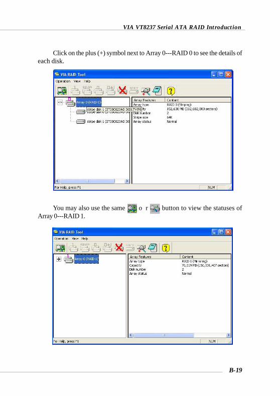
VIA VT8237 Serial ATA RAID Introduction
B-19
Click on the plus (+) symbol next to Array 0---RAID 0 to see the details ofeach disk.
You may also use the same o r button to view the statuses ofArray 0---RAID 1.
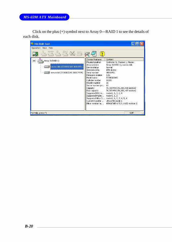
MS-6590 ATX Mainboard
B-20
Click on the plus (+) symbol next to Array 0---RAID 1 to see the details ofeach disk.