Embed Size (px)
Citation preview

KSZ8795 Evaluation Board User’s Guide
Micrel Inc. Page 1 7/25/2014
KSZ8795CLX-EVAL Board User’s Guide
KSZ8795CLX Family Integrated 5-port Managed Switch with 4 10/100 Copper Ports and Port 5 GMII/RGMII/MII/RMII Up-link Interface
Rev 1.0 July 2014

KSZ8795 Evaluation Board User’s Guide
Micrel Inc. Page 2 7/25/2014
Table of contents
1.0 Introduction ................................................................................................................................. 4 2.0 Features ....................................................................................................................................... 4 3.0 Evaluation Kit Contents .............................................................................................................. 4 4.0 Hardware Description ................................................................................................................. 5
4.1 Strap in Mode .......................................................................................................................... 6 4.1.1 Feature Setting Jumpers ................................................................................................... 7
4.2 SPI Mode ................................................................................................................................ 9 4.3 MDC/MDIO Interface for MIIM Registers ............................................................................ 9 4.4 10/100 Ethernet Ports ............................................................................................................ 10 4.5 LED indicators ...................................................................................................................... 10 4.6 GMII/RGMII/MII/RMII Ports Configuration....................................................................... 11
5.0 Software Tools Description ...................................................................................................... 14 5.1 Introducing Application Software Tools .............................................................................. 14 5.2 Window Driver Installation First .......................................................................................... 14 5.3 Installation Application Software Tools ............................................................................... 17 5.4 DOS SPI Tool ....................................................................................................................... 20 5.5 MDC/MDIO MIIM Software Tool ....................................................................................... 20 5.6 Window SPI Software Tool .................................................................................................. 22 5.7 LinkMD Software Tool......................................................................................................... 23
6.0 Reference Documents ............................................................................................................... 25 7.0 Bill of Material .......................................................................................................................... 25 8.0 Schematics ................................................................................................................................ 25

KSZ8795 Evaluation Board User’s Guide
Micrel Inc. Page 3 7/25/2014
List of Figures and Tables
Figure 1 KSZ8795 Evaluation Board ............................................................................................... 5 Figure 2 KSZ8795 Evaluation Board Block Diagram ...................................................................... 6 Table 1 General Setting Jumpers ...................................................................................................... 7 Table 2 SW5-GMII/RGMII/MII/RMII Setting Jumpers .................................................................. 7 Table 3 Power Setting Jumpers......................................................................................................... 8 Table 4 Other Setting Jumpers .......................................................................................................... 8 Table 5 SPI Slave Mode Related Setting by Jumpers ....................................................................... 9 Table 6 Access MDC/MDIO MIIM Registers Setting by Jumpers ................................................ 10 Table 5 LED Modes ........................................................................................................................ 10 Table 6 GMII/RGMII/MII/RMII Modes Settings .......................................................................... 11 Revision History Revision Date Change 1.0 7/25/14 Initial release

KSZ8795 Evaluation Board User’s Guide
Micrel Inc. Page 4 7/25/2014
1.0 Introduction The KSZ8795 family is Micrel Operations’ new generation integrated 5-port switch. The KSZ8795CLX is one of KSZ8795 family. KSZ8795CLX contains four MAC/PHYs for four copper ports and one GMAC5 interface with configurable GMII/RGMII/MII/RMII interfaces for Gigabit up-link. The device had been designed with cost sensitive systems in mind but still offers a multitude of new features such as port based security ACL filtering, 802.1az EEE, LinkMD and so on. Also support port and tag based VLAN; QoS priority; SPI and MDC/MDIO interfaces for the registers access. The KSZ8795 family is an excellent choice in broadband gateway applications, integrated broadband router applications, managed media converter, industrial automatic, automotive, etc. fields and as a standalone switch. The KSZ8795CLX evaluation board is designed to allow the user to experience first-hand the rich feature set of this exciting new product. The evaluation board is highly configurable and easy to use.
2.0 Features • Micrel KSZ8795 Integrated 5-port 10/100 Managed Ethernet Switch • 4 RJ-45 Jacks for Ethernet LAN and WAN Interfaces with Corresponding Isolation Magnetics. • Auto MDI/MDIX on All Ports. • 1 PHY mode and 1 MAC mode Connectors are for the GMII/RGMII/MII/RMII interfaces.
Easily set each interface mode by jumpers. • Easily set to different VDDIO of 3.3V, 2.5V and 1.8V by jumpers. • 1 USB Port Interface Configurable to Emulate an SPI or MDC/MDIO Interface for all control
registers and all MIIM registers access by using Window GUI and DOS based software tools. • 2 LEDs Per Port with 4 LED modes to Indicate the Status and Activity • The board powered can be used by either USB port or 5V DC power supply.
3.0 Evaluation Kit Contents The KSZ8795 Evaluation kit includes the following: • KSZ8795 Evaluation Board Rev. 1.x • KSZ8795 Evaluation Board User’s Guide Rev 1.x • Micrel SPI/MDIO Configuration Software tools • KSZ8795 Evaluation Board Schematics and BOM • KSZ8795 Evaluation Board PCB file, Gerber file and IBIS module. • The software, reference schematics and other design information will be found in the Design
Kit (Design Package) of the KSZ8795 Ethernet switch products on Micrel website. (Contact your Micrel FAE for the latest schematic).
• The USB cable and 5V DC power supply are not included.

KSZ8795 Evaluation Board User’s Guide
Micrel Inc. Page 5 7/25/2014
4.0 Hardware Description The KSZ8795 evaluation board is in a compact form factor and can sit on a bench near a computer with USB connector. There are three options for configuration: strap in mode; SPI mode and MDIO mode. Strap-in mode configuration is easily done with on board jumper options. SPI mode and MDIO mode are accomplished through a built in USB port interface. Using Micrel SPI and MDIO software and your PC, you can configure the KSZ8795 device on board by the USB port. Using Micrel SPI software and your PC, you can access the KSZ8795’s full feature set registers by the USB to SPI interface. Or using Micrel MDC/MDIO software with your PC, you can access the KSZ8795’s MIIM PHY registers by general MDC/MDIO interface. The board also features the connectors for the Switch GMII/RGMII/MII/RMII interface. These are to facilitate connections from the switch to an external MAC/GMAC or PHY/GPHY.
The KSZ8795 evaluation board is easy to use. There are programmable LED indicators for link and activity on all ports and a power LED. A manual reset button allows the user to reset the board without removing the power plug. A standard 5VDC power supply can be used by the power jack so that the user can supply power from any 110-240 Volt AC wall or bench socket, and the power also can be provided by USB port when close pin 2-3 of the JP24 jumper.
Figure 1 KSZ8795 Evaluation Board

KSZ8795 Evaluation Board User’s Guide
Micrel Inc. Page 6 7/25/2014
FIFO, Flow Control, VLAN Tagging, Priority
USBDevice
USBPort
Port 1 Port 2 Port 3 Port 4 SW5-GMII/RGMII SW5-MII/RMII
Mag 1 Mag 2
5 VDCJack
3.3VRegulator
1.2VRegulator
ResetButton
KSZ8795
Mag 3 Mag 4
Figure 2 KSZ8795 Evaluation Board Block Diagram
4.1 Strap in Mode Strap in configuration mode is the quickest and easiest way to get started. In the default mode, the KSZ8795 acts as a stand-alone 4 port switch and one RGMII up-link. The user has to simply set the board’s configuration jumpers to the desired settings and apply power to the board. The user can also change jumper settings while power is applied to the board and press the convenient manual reset button for the new settings to take effect. Note that even if there is no external strap in values are set, internal pull up and pull down resistors will set the KSZ8795 default configuration. Section 4.1.1 covers each jumper on the board and describes its function. The KSZ8795 will start automatically after power up or reset.

KSZ8795 Evaluation Board User’s Guide
Micrel Inc. Page 7 7/25/2014
4.1.1 Feature Setting Jumpers The evaluation board provides jumpers to allow the user to easily set strap in configurations for the KSZ8795. Tables below describe the jumpers and their functions in the open or closed state.
Table 1 General Setting Jumpers
Jumper KSZ8795 Signal Description Closed or Open
Description Closed or Open
JP1 5-pin SPI signals Open for SPI 1-2 Close for MDC/MDIO JP3 3-pin SCL_MDC 1-2 for KSZ8795 SPI or
MDC/MDIO 2-3 for external PHY MDC
JP4 3-pin SDA_MDIO 1-2 for KSZ8795 SPI or MDC/MDIO
2-3 for external PHY MDIO
JP6 3-pin SPI/MDIO select 1-2 SPI slave mode 2-3 MDC/MDIO-MIIM access JP7 2-pin Gigabit and
10/100 mode select
Open: Gigabit rate in GMII/RGMII mode (LED1_0 has internal pull-up as default)
Closed: 10/100Mbps rate in GMII/RGMII mode
JP8 2-pin Clock and Normal mode select
Open: Clock source from 25MHz on XI/XO pin in SW5-RMII normal mode (LED1_1 has internal pull-up as default)
Closed: Clock source from 50MHz on TXC5 pin in SW5-RMII normal mode.
JP9 2-pin Output 25MHz clock for system using
Open: Output 25MHz on REFCLKO pin (LED2_0 has internal pull-up as default)
Closed: Disable 25MHz output on REFCLKO pin
JP10 2-pin Select for MAC/PHY mode in SW5-MII or Clock/Normal mode in SW5-RMII
Open: GMAC/MAC mode in SW5-GMII/MII. Clock mode in SW5-RMII
Closed: GPHY/PHY mode in SW5-GMII/MII. Normal mode in SW5-RMII
Table 2 Port 5 SW5-GMII/RGMII/MII/RMII Setting Jumpers
Jumper JP12
Jumper JP11
Up-Link Description
Closed Closed SW5-MII Closed Open SW5-RMII Open Closed SW5-GMII Open Open SW5-RGMII (default)

KSZ8795 Evaluation Board User’s Guide
Micrel Inc. Page 8 7/25/2014
Table 3 Power Setting Jumpers
JP24 3-pin 5V select 1-2 Closed: 5V from 5V DC
Jack.
2-3 Closed: 5V USB connector.
JP19 2-pin 1.2V analog power
Closed: Provide 1.2V analog power (default)
Open: Measure 1.2V analog power current.
JP20 2-pin 1.2V digital power
Closed: Provide 1.2V digital power (default)
Open: Measure 1.2V digital power current.
JP21 2-pin 3.3V analog power
Closed: Provide 3.3V analog power (default)
Open: Measure 3.3V analog power current.
JP19 2-pin 1.2V analog power
Closed: Provide 1.2V analog power (default)
Open: Measure 1.2V analog power.
JP22 2-pin 1.8V or 2.5V digital I/O select
Closed: Select 1.8V digital I/O with JP23 1-2 Closed
Open: Select 2.5V digital I/O with JP23 1-2 Closed
JP23 3-pin 1.8V/2.5V or 3.3V digital I/O select
1-2 Closed: Select 1.8/2.5V digital I/O with JP22 Closed
2-3 Closed: Select 3.3V digital I/O with JP22 Open
Table 4 Other Setting Jumpers
JP13 3-pin Power for LED 1-2 Closed: Power from
VDDIO. 2-3 Closed: Power from 3.3V (default).
JP18 3-pin Power for an external PHY
1-2 Closed: Power from 3.3V for PHY EVAL board.
2-3 Closed: Power from 5V for PHY EVAL board.
JP15 3-pin Power for Reset of USB controller
1-2 Closed: 3.3V reset (default).
2-3 Closed: 5V reset.
JP25 3-pin USB I/O power 1-2 Close: 3.3V I/O (default) 2-3 Close: 5V I/O. JP26 2-pin Power for voltage
shift buffer Closed: normal Open: Measure device power
without buffer. JP27 2x4-pin
1-2, 3-4, 5-6, 7-8 Closed: normal
Open: Isolate with USB Controller

KSZ8795 Evaluation Board User’s Guide
Micrel Inc. Page 9 7/25/2014
4.2 SPI Mode From SPI interface to the KSZ8795, use a USB to SPI converter that allows accessing all of the KSZ8795 features and registers. The user can easily access the SPI interface using a computer connected to the evaluation board’s USB port interface. Micrel provides a Windows GUI based program for the user to evaluate the KSZ8795’s full feature set. KSZ8795’s SPI interface will be able to access all static MAC table, the VLAN table, dynamic MAC address table, the MIB counters and all enhanced features.
To prepare the KSZ8795 evaluation board for SPI mode configuration follow these steps: 1. Copy the Micrel provided SPI interface software on your computer. 2. Set jumpers as specified in Table 5 below for SPI slave mode.
Table 5 SPI Slave Mode Related Setting by Jumpers
Jumper Description
JP6 1-2 Closed JP3 1-2 Closed JP4 1-2 Closed
3. Connect the computer’s USB port to the KSZ8795 board with a USB port cable. 4. There are two ways to power up the evaluation board:
a). Connect the 5V DC power supply to the KSZ8795 when JP24 pin1-2 is closed (default). b). 5V DC power source from the USB port when JP24 pin 2-3 is closed. 5. Open the Windows and navigate to the directory where the Window SPI file is stored. Click its
icon to invoke the software. 6. Program the desired settings using the Micrel SPI interface software. See the software
operation description section for details.
4.3 MDC/MDIO Interface for MIIM Registers From MDC/MDIO interface to the KSZ8795, use a USB to MDC/MDIO converter that allows accessing all of PHY related registers. The user can easily access the MDC/MDIO interface using a computer connected to the evaluation board’s USB port interface. Micrel provides Windows based programs for the user to evaluate for MIIM registers access. For the MIIM software to be used all of PHY related registers, please use the MDIO software tool in the folder the software directory.
To prepare the KSZ8795 evaluation board for MDC/MDIO configuration, please follow these steps:

KSZ8795 Evaluation Board User’s Guide
Micrel Inc. Page 10 7/25/2014
Table 6 Access MDC/MDIO MIIM Registers Setting by Jumpers
Jumper Description JP1 1-2 Closed JP6 2-3 Closed JP3 1-2 Closed JP4 1-2 Closed
1. Set jumpers as specified in Table 6 for MDC/MDIO MIIM registers access. 2. Connect the computer’s USB port to the KSZ8795 board with a USB port cable. 3. There are two ways to power up the evaluation board: a). Connect the 5V DC power supply to the KSZ8795 when JP24 pin1-2 is closed.
b). 5V DC power source from the USB port when JP24 pin 2-3 is closed. 4. Open the Windows and navigate to the directory where the Window MDC/MDIO files are
stored. Click its icon to invoke the software. 5. Program the desired settings using the Micrel MDC/MDIO software. See the software
operation description section for details.
4.4 10/100 Ethernet Ports There are five 10/100 Ethernet ports on the KSZ8795 evaluation board. The ports J1, J2, J3 and J4 are the standard RJ45 connectors and using CAT-5 cables. Each port can be used as either an uplink or downlink. All ports support auto MDI/MDIX so there is no need for cross over cables.
J1 = RJ45 connector for port 1 J2 = RJ45 connector for port 2 J3 = RJ45 connector for port 3 J4 = RJ45 connector for port 4
4.5 LED indicators Ethernet Port LEDs
There are four columns of LED indicators on the board, one column for each of the four ports. The LED indicators are programmable to two different modes. You can program the LED mode through Register 11 bits [5:4]. The mode definitions are shown in Table below. There are two LEDs per port. The naming convention is “LEDx_y”, where “x” is the port number, and “y” is the number of the LED for that port.
Table 5 LED Modes
Register 11 bits [5:4] 00 01 10 11 LEDx_1 Speed ACT Duplex Duplex LEDx_0 Link/ACT Link Link/ACT Link
LED1_y are assigned to port 1 LED2_y are assigned to port 2 LED3_y are assigned to port 3 LED4_y are assigned to port 4

KSZ8795 Evaluation Board User’s Guide
Micrel Inc. Page 11 7/25/2014
Power LED The board also has a power LED D3 for the 3.3V power supply. D3 LED indicates 3.3V Power on and off. PME_N LED The board also has a LED D2 for the Wake-on-LAN when set its mask register 125. D2 LED is turn on to indicate the Wake-on-LAN to be asserted. INT_N LED The board also has an Interrupt LED D4 for the Link status change when set the interrupt mask register 125. D4 LED is turn on to indicate the interrupt to be asserted.
4.6 GMII/RGMII/MII/RMII Ports Configuration There are two connectors of J5 and J6 on the KSZ8795-EVAL board. J5 is PHY mode connector that can be connected to an external MAC mode connector with GMII/RGMII/MII/RMII interfaces, J6 is MAC mode connector that can be connected to an external PHY mode connector with GMII/RGMII/MII/RMII interfaces, some examples as below. Set jumpers as specified in Table 6 below for multiple CPU interfaces of GMII/, RGMII, MII and RMII and their modes.
Table 6 GMII/RGMII/MII/RMII Modes Settings
JP12 JP11 JP10 JP8 JP7 GMAC5 Interface Modes
Closed Closed Open N/A N/A SW5-MII MAC mode
Closed Closed Closed N/A N/A SW5-MII PHY mode
Closed Open Open Open N/A SW5-RMII clock mode
Closed Open Open Open N/A SW5-RMII normal mode with clock source from XI/XO 25MHz clock
Closed Open Open Closed N/A SW5-RMII normal mode with clock source from TXC5 of RMII interface.
Open Closed Open N/A Open SW5-GMII GMAC mode with Gigabit mode.
Open Closed Closed N/A Open SW5-GMII GPHY mode with Gigabit mode.
Open Closed Open N/A Closed SW5-GMII MAC mode with 10/100 mode.
Open Closed Closed N/A Closed SW5-GMII PHY mode with 10/100 mode.
Open Open N/A N/A Open SW5-RGMII with Gigabit mode.
Open Open N/A N/A Closed SW5-RGMII with 10/100 mode.

KSZ8795 Evaluation Board User’s Guide
Micrel Inc. Page 12 7/25/2014
Some Examples for GMII/RGMII/MII/RMII evaluation connection: 1. KSZ8795CLX-EVAL board with KSZ8081MNX/MLX PHY board for MII access.
KSZ8795 can be set to SW5-MII MAC mode, this MAC-PHY connection Figure shows below. JP18 1-2 should be closed due to KSZ8081MNX/MLX evaluation boards request 3.3V power.
2. KSZ8795CLX-EVAL board with KSZ8081RNA/RND PHY board for RMII access. KSZ8795 can be set to SW5-RMII normal mode with KSZ8081RNA-EVAL board or set to SW5-RMII clock mode with KSZ8081RND-EVAL board, the Figure shows below.
3. From the Figure shows above, when KSZ8795-EVAL board connect with KSZ8081 family PHY evaluation boards for RMII access. JP18 Pin 2-3 on KSZ8795CLX-EVAL board need to be closed for the connector with 5V power that is KSZ8081RNA/RND EVAL board request. When KSZ8795CLX-EVAL board hooks up with KSZ8081RND board, KSZ8795 should be set to RMII clock mode. When KSZ8795CLX-EVAL board hooks up with KSZ8081RNA board, KSZ8795 should be set to RMII normal mode.

KSZ8795 Evaluation Board User’s Guide
Micrel Inc. Page 13 7/25/2014
4. Two KSZ8795CLX-EVAL boards with back to back connection for GMII/RGMII access. a). One can be set to SW5-GMII MAC mode, another one set to SW5-GMII PHY mode. b). One can be set to SW5-RGMII with Gbps or Mbps mode, another one set to SW5-RGMII with Gbps or Mbps mode, the connection Figure shows below.
c). Two KSZ8795CLX-EVAL boards connect together with GMII/RGMII Gigabit mode, can be used for a 8-port non-blocking standalone switch, or evaluate for SW5-GMII/RGMII port. In RGMII mode, the RGMII configuration needs to be checked, the register setting is necessary sometime. Please see a table of RGMII clock delay configuration in SW5-RGMII Interface section of the datasheet for the setting details. For example, one board set Register 86 bits [4:3] =’01’ (default), another board must be set same Register 86 bits [4:3] =’01’. If one board set Register 86 bits [4:3] =’10’, another board must be set same Register 86 bits [4:3] =’10’. If one board set Register 86 bits [4:3] =’11’, another board must be set Register 86 bits [4:3] =’00’ for the correct RGMII configuration.
5. KSZ8795CLX-EVAL board with KSZ9031RNX-EVAL board for RGMII access.
KSZ8795 can be set to SW5-RGMII mode, the Figure shows below. JP18 2-3 should be closed due to KSZ9031RNX evaluation board requests 5V power.
a). Both boards can set 1.8V, 2.5V and 3.3V VDDIO and can set register 86 bits[4:3] of KSZ8795CLX if it is necessary. Please see RGMII section of datasheet for details.

KSZ8795 Evaluation Board User’s Guide
Micrel Inc. Page 14 7/25/2014
5.0 Software Tools Description
5.1 Introducing Application Software Tools The Design Kit provides some software tools to support SPI access for all registers and MDC/MDIO access for MIIM registers. The installation file is located folders in the software tool directory within subdirectory of Window SPI_MDIO_Tools, this file name is MicrelSwitchPhyTool_x.xx.msi.
5.2 Window Driver Installation First Before use the Window based application software tool, the support drivers need to be installed to PC/Laptop first and this installation is just one times only. When connect one standard USB cable with type A and type B connectors between the evaluation board and PC computer first time, the Found New Hardware Wizard window will pop-up and then follow the instructions step by step as below.
. Choose ‘No, not this time’ radio button and click the ‘Next’ button.

KSZ8795 Evaluation Board User’s Guide
Micrel Inc. Page 15 7/25/2014
Choose the ‘Install from a list or specific location (Advanced)’ radio button and click the ‘Next’ button.
Click the ‘Include this location in the search’ check box, and use ‘Browse’ button to select the ‘C:\MicrelEthernetChipConfig\D2XXDriver\CDM 2.02.04 WHQL Certified’ directory and click the ‘Next’ button. The window will install the drivers from this location.

KSZ8795 Evaluation Board User’s Guide
Micrel Inc. Page 16 7/25/2014
Click ‘Finish’ button. The Window will install another driver called ‘USB Serial Converter B’. After the drivers installed, Window Device Manager will show ‘USB Serial Converter A’ and ‘USB Serial Converter B’ as below figure. That means the installation successful.

KSZ8795 Evaluation Board User’s Guide
Micrel Inc. Page 17 7/25/2014
5.3 Installation Application Software Tools In the Design Kit, the installation file is located folders in the software tool directory within subdirectory of Window SPI_MDIO_Tools, this file name is MicrelSwitchPhyTool_x.xx.msi. Double click this file name, an installation Window will pop-up and then follow the instructions step by step as below.
In this pop-up Window, this application software tools can be assigned to default Micrel directory in above window shown or is assigned to specified folder what you want. Click ‘Next’ button, next Window will pop-up as below.

KSZ8795 Evaluation Board User’s Guide
Micrel Inc. Page 18 7/25/2014
Click ‘Next’ button to start the installation.
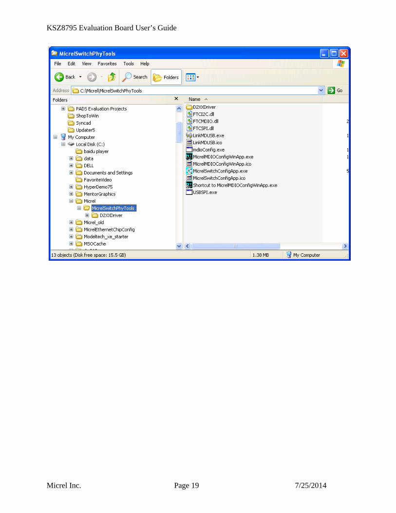
Click ‘Close’ button to finish the installation. All application software tools are installed into the default Micrel directory or assigned directory in installation as below.
KSZ8795 Evaluation Board User’s Guide
Micrel Inc. Page 19 7/25/2014

KSZ8795 Evaluation Board User’s Guide
Micrel Inc. Page 20 7/25/2014
5.4 DOS SPI Tool This is a simple and powerful tool to access all register. The tool located in the default or assigned folder in the installation. There is an USBSPI.exe file which can be executed directly by clicking its icon. Before run the software tool, the SPI jumper setting should follows Table 5 in 4.3 SPI mode section and USB cable is plugged in both KSZ8795CLX-EVAL board and PC/Laptop. After click its icon, a DOS Window will pop up as follow:
Type a ‘help’ and press Enter, all commands will display as follows, For Read or Write registers, reg is the offset address of the register, value is Hex number. The ‘run file’ command can execute multiple commands by a script file, the script file is a .txt file which can be created by any edit tools.
run xxxx.txt //will run the .txt script file. 5.5 MDC/MDIO MIIM Software Tool This is a simple and powerful tool to access MIIM register. The tool located in the default or assigned folder in the installation. There is a MicrelMDIOConfigWinApp.exe file which can be executed directly by clicking its icon. Before run the software tool, the MDC/MDIO jumper setting should follows Table 6 in 4.4 MDC/MDIO mode section and USB cable is plugged in both KSZ8795CLX-EVAL board and PC/Laptop. After click its icon, a GUI Window will pop up as follow:

KSZ8795 Evaluation Board User’s Guide
Micrel Inc. Page 21 7/25/2014
Select ‘KSZ8795CLX switch’ and click Next button, Pop up a MDIO MIIM Configuration window as below: In this window, all of MIIM registers on 4 PHYs can be read and written directly. Click the button of ‘Down’ or ‘Up’, all MII registers will display for current configuration. Check any writable bits of registers and click ‘Write’ button, the value of registers will be changed.

KSZ8795 Evaluation Board User’s Guide
Micrel Inc. Page 22 7/25/2014
5.6 Window SPI Software Tool This is a powerful tool to access all register. The tool located in the default or assigned folder in the installation. There is a MicrelSwitchConfigApp.exe file which can be executed directly by clicking its icon. Before run the software tool, the SPI jumper setting should follows Table 5 in 4.3 SPI mode section and USB cable should be plugged in both KSZ8795CLX-EVAL board and PC/Laptop. After click its icon, a GUI Window will pop up as follow:
The default is SPI interface to do switch configuration. From the device selection window to select any devices then press ‘Continue’ button or click ‘Continue’ button directly, the software tool can detect devices automatically. A control Window will be pop up as follow.

KSZ8795 Evaluation Board User’s Guide
Micrel Inc. Page 23 7/25/2014
All register can be read/ written in the window. The control Window includes all application registers, static MAC table, VLAN table, dynamic table and MIB counters that are supported by SPI. The software can save and open the configuration file as a back-up.
5.7 LinkMD Software Tool This is a simple and powerful tool to test Micrel LinkMD feature. The tool is in the installation folder. There is a LinkMDUSB.exe file which can be executed directly by clicking its icon.
After click the icon of this executed file, a GUI Window will pop up as follow:
Select one part and clik ‘Next’ button, using SPI interface and clik ‘Next’ button again, pop up a test windown as below:

KSZ8795 Evaluation Board User’s Guide
Micrel Inc. Page 24 7/25/2014
An example for CAT-5 cable diagnostic with open on port 1, just click ‘TEST’ button, a test result shows as below.

KSZ8795 Evaluation Board User’s Guide
Micrel Inc. Page 25 7/25/2014
The test result shows both MDIX mode for pair 3-6 and MDI mode for 1-2 pair. The detail LinkMD diagnostic testing configuration is described in the datasheet.
6.0 Reference Documents KSZ8795CLX Data Sheets (Contact Micrel for Latest Datasheet), KSZ8795 Design Package includes all design information as a Design kit. The Design Kit will be found on Micrel website (Contact Micrel for the updates).
7.0 Bill of Material Please see the detail BOMs in the BOM folder of the hardware design package for the KSZ8795CLX Evaluation Boards.
8.0 Schematics Please see the schematics of the evaluation board and reference design in the schematics folder of the hardware design package (Design kit) for the KSZ8795 Evaluation Board.
Magnetics Vendors: See the datasheets for the recommendation.
MICREL, INC. 1849 FORTUNE DRIVE SAN JOSE, CA 95131 USA TEL +1 (408) 944-0800 FAX +1 (408) 474-1000 WEB http:/www.micrel.com
The information furnished by Micrel in this data sheet is believed to be accurate and reliable. However, no responsibility is assumed by Micrel for its use. Micrel reserves the right to change circuitry and specifications at any time without notification to the
customer.
Micrel Products are not designed or authorized for use as components in life support appliances, devices or systems where malfunction of a product can reasonably be expected to result in personal injury. Life support devices or systems are devices or systems that (a) are intended for surgical implant into the body or (b) support or sustain life, and whose failure to perform can be reasonably expected to result in a significant injury to the user. A Purchaser’s use or sale of Micrel Products for use in life support
appliances, devices or systems is a Purchaser’s own risk and Purchaser agrees to fully indemnify Micrel for any damages resulting from such use or sale.
© 2013 Micrel, Incorporated.