Embed Size (px)
Citation preview
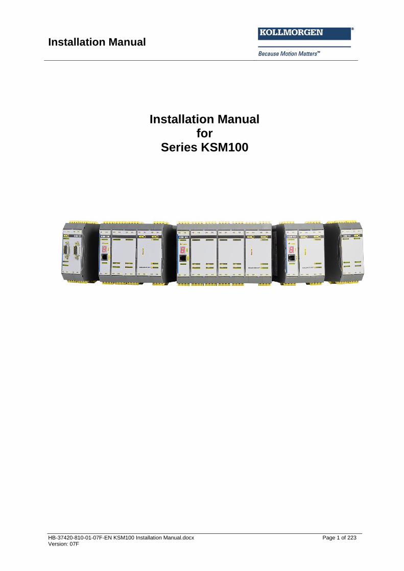
Installation Manual
HB-37420-810-01-07F-EN KSM100 Installation Manual.docx Page 1 of 223 Version: 07F
Installation Manual for
Series KSM100
Installation Manual
HB-37420-810-01-07F-EN KSM100 Installation Manual.docx Page 2 of 223 Version: 07F
Installation instructions for basic devices KSM100-1, KSM100-2, KSM100-4, KSM121, KSM121-2, KSM122, KSM 122A, KSM122-2, KSM131 and KSM131R. For information about KSM100 modules with communication interface, see manuals KSM 53, KSM 54 or KSM 55. Note: The German version is the original version of the installation manual. Status: 06/2013 Valid from FW release 2.1.0.6 for KSM100-x (basic devices) And from FW release 2.1.0.2 for KSM12x, KSM13x (Extension devices) Subject to change without prior notification
The contents of this documentation has been collated with greatest care and corresponds with our present status of information. However, we would like to point out, that this document cannot always be updated at the same time as the technical further development of the products. Information and specifications can be changed at any time. Please keep yourself informed about the current version under www.kollmorgen.com. Devices of the Kollmorgen Europe GmbH Pempelfurtstraße 1 DE-40880 Ratingen
Installation Manual
HB-37420-810-01-07F-EN KSM100 Installation Manual.docx Page 3 of 223 Version: 07F
Contents 1 IMPORTANT NOTES ............................................................................................. 6 1.1 Definitions .............................................................................................................................................. 6 1.2 Co-valid documents ................................................................................................................................ 7 1.3 Abbreviations used ................................................................................................................................. 7 2 SAFETY REGULATIONS ....................................................................................... 9 2.1 Intended use ........................................................................................................................................... 9 2.2 General safety regulations ...................................................................................................................... 9 2.3 Operation and service .......................................................................................................................... 11 2.4 Transport/storage ................................................................................................................................ 11 3 DEVICE TYPES .................................................................................................... 12 3.1 Module overview.................................................................................................................................. 13 3.2 Characteristic data of device ................................................................................................................. 14
3.2.1 Basic modules ...................................................................................................................... 14 3.2.1.1 System module KSM 100-1 .............................................................................................. 14 3.2.1.2 System module KSM 100-2 .............................................................................................. 16 3.2.1.3 System module KSM 100-4 .............................................................................................. 18
3.2.2 Extension modules ............................................................................................................... 20 3.2.2.1 Extension module KSM 121 ............................................................................................. 20 3.2.2.2 Extension module KSM 121-2 .......................................................................................... 22 3.2.2.3 Extension module KSM 122 (A) ....................................................................................... 24 3.2.2.4 Extension module KSM 122-2 .......................................................................................... 26 3.2.2.5 Extension group KSM131 ................................................................................................. 28
3.3 Identification ........................................................................................................................................ 30 3.3.1 Basic device .......................................................................................................................... 30 3.3.2 Extension device................................................................................................................... 30
4 SAFETY RELATED CHARACTERISTICS ........................................................... 31 4.1 General design, safety related architecture and characteristic data ..................................................... 31 4.2 Safety related characteristic data and wiring for the connected sensors .............................................. 35
4.2.1 Digital sensors ...................................................................................................................... 35 4.2.1.1 Characteristics of sensors / input elements ...................................................................... 35 4.2.1.2 DC digital sensors/inputs .................................................................................................. 36 4.2.1.3 Classification of digital safety inputs ................................................................................. 40 4.2.1.4 Exemplary connections of digital sensors/input elements ................................................ 41 4.2.1.5 Overview of achievable PI for digital safety inputs ........................................................... 46
4.2.2 Sensors for speed and/or position detection ........................................................................ 48 4.2.2.1 General safety related structure of the sensor interface for position and/or speed ......... 48 4.2.2.2 General diagnostic measures for encoder interface......................................................... 49 4.2.2.3 Encoder types and their combination, diagnostic data ..................................................... 50 4.2.2.4 Specific diagnostic measures with regard to the encoder type used ............................... 54 4.2.2.5 Safety relevant cut-off thresholds encoder systems for position and speed detection .... 55 4.2.2.6 Safety related assessment of encoder types or there combination ................................. 58
4.2.3 Analog sensors ..................................................................................................................... 60 4.2.3.1 Exemplary connection of analog sensors ......................................................................... 61
4.3 Safety related characteristic data and wiring of the outputs ................................................................ 62 4.3.1 Characteristic of the output elements ................................................................................... 62 4.3.2 Diagnoses in the cut-off circuit ............................................................................................. 63
4.3.2.1 Diagnostic Functions ........................................................................................................ 63 4.3.2.2 Overview DC with respect to the chosen diagnostics functions ....................................... 64
4.3.3 Basic outputs ........................................................................................................................ 65 4.3.3.1 Characteristic data of the basic outputs ........................................................................... 65 4.3.3.2 Wiring examples basic outputs ......................................................................................... 67
4.3.4 Configurable I/O as outputs .................................................................................................. 74 4.3.4.1 Classification of the I/O when used as output .................................................................. 74 4.3.4.2 Wiring example for outputs of extension module ............................................................. 75 4.3.4.3 Overview of achievable PI for digital safety outputs ......................................................... 80
Installation Manual
HB-37420-810-01-07F-EN KSM100 Installation Manual.docx Page 4 of 223 Version: 07F
5 CONNECTION AND INSTALLATION .................................................................. 82 5.1 General notes on installation ................................................................................................................ 82 5.2 Installation and assembly of the KSM100 module ................................................................................ 83 5.3 Installation of backplane bus system .................................................................................................... 83
5.3.1 Arrangement examples ........................................................................................................ 84 5.3.1.1 KSM100-1 + KSM122 + KSM1xx ..................................................................................... 84 5.3.1.2 KSM100-4 + KSM121-2 + KSM1xx .................................................................................. 84
5.4 Assembling the modules ....................................................................................................................... 85 5.4.1 Assembly on C-rail................................................................................................................ 85 5.4.2 Assembly on backplane bus ................................................................................................. 86
5.5 Installation and configuration I/O-extension KSM131 .......................................................................... 88 5.5.1 Log on KSM131 to basic group ............................................................................................ 88 5.5.2 Physical address configuration KSM131 .............................................................................. 89 5.5.3 Configuration of the I/O-assignment KSM131 ...................................................................... 89 5.5.4 Logic address configuration KSM131 ................................................................................... 90
5.6 Terminal assignment ............................................................................................................................ 91 5.6.1 Terminal assignment KSM 100-1 ......................................................................................... 91 5.6.2 Terminal assignment KSM 100-2 ......................................................................................... 91 5.6.3 Terminal assignment KSM 100-4 ......................................................................................... 92 5.6.4 Terminal assignment KSM 121 ............................................................................................ 93 5.6.5 Terminal assignment KSM 121-2 ......................................................................................... 93 5.6.6 Terminal assignment KSM 122 ............................................................................................ 94 5.6.7 Terminal assignment KSM 122A .......................................................................................... 94 5.6.8 Terminal assignment KSM 122-2 ......................................................................................... 95 5.6.9 Terminal assignment KSM 122-2A ....................................................................................... 96 5.6.10 Terminal assignment KSM 131 ............................................................................................ 97
5.7 External 24 VDC – power supply ........................................................................................................... 98 5.8 Connection of the external encoder supply .......................................................................................... 99
5.8.1 Incremental, HTL, SIN/COS, SSI ......................................................................................... 99 5.8.2 Resolver .............................................................................................................................. 100
5.9 Connection of digital inputs ................................................................................................................ 101 5.10 Connection of analog inputs ............................................................................................................... 102 5.11 Connection of position and speed sensors .......................................................................................... 102
5.11.1 General notes ..................................................................................................................... 102 5.11.2 Assignment of encoder interface ........................................................................................ 103 5.11.3 Connection variants ............................................................................................................ 104
5.11.3.1 Connection of an absolute encoder as master ........................................................... 104 5.11.3.2 Connection of an absolute encoder as slave ............................................................. 105 5.11.3.3 Connecting an incremental encoder with TTL-signal level ......................................... 106 5.11.3.4 Connection of a SIN/COS encoder............................................................................. 107 5.11.3.5 Connection of a resolver as master ............................................................................ 108 5.11.3.6 Connection of a resolver as slave .............................................................................. 109
5.12 Configuration of measuring distances ................................................................................................. 110 5.12.1 General description of encoder configuration ..................................................................... 110 5.12.2 Sensor type ......................................................................................................................... 110
5.12.2.1 Absolute encoder: ....................................................................................................... 110 5.12.2.2 Incremental encoder: .................................................................................................. 113 5.12.2.3 SinusCosinus encoder – standard mode ................................................................... 113 5.12.2.4 SinusCosinus encoder – high resolution mode: ......................................................... 113 5.12.2.5 Proximity switch .......................................................................................................... 114 5.12.2.6 Extended monitoring proximity switch / proximity switch............................................ 115 5.12.2.7 HTL - Sensor .............................................................................................................. 116 5.12.2.8 Resolver ...................................................................................................................... 116
6 RESPONSE TIMES OF THE KSM ..................................................................... 117 6.1 Response times in standard operation ............................................................................................... 117 6.2 Response time for FAST_CHANNEL ..................................................................................................... 118 6.3 Response times for fault distance monitoring .................................................................................... 119
Installation Manual
HB-37420-810-01-07F-EN KSM100 Installation Manual.docx Page 5 of 223 Version: 07F
6.4 Response times when using digital inputs and outputs on the extension groups ............................... 121 7 START-UP .......................................................................................................... 123 7.1 Procedure ........................................................................................................................................... 123 7.2 Making sequences .............................................................................................................................. 123 7.3 LED display ......................................................................................................................................... 124 7.4 Parameterization ................................................................................................................................ 125 7.5 Function test ....................................................................................................................................... 125 7.6 Validation ........................................................................................................................................... 125 8 SAFETY RELATED EXAMINATION .................................................................. 126 9 MAINTENANCE ................................................................................................. 127 9.1 Modification / handling changes to the device ................................................................................... 127 9.2 Exchanging a module .......................................................................................................................... 127 9.3 Maintenance intervals ........................................................................................................................ 127 10 TECHNICAL DATA ......................................................................................... 128 10.1 Environmental conditions ................................................................................................................... 128 10.2 Safety related characteristic data ....................................................................................................... 128 11 FAULT TYPES KSM ....................................................................................... 129 11.1 Fault indication ................................................................................................................................... 129
11.1.1 KSM100-x without extension modules ............................................................................... 129 11.1.2 KSM100 with expansion modules ...................................................................................... 129
11.2 Alarm List KSM100 .............................................................................................................................. 130 Fatal Fault list KSM100 .................................................................................................................................... 165
12 ENCODER TYPES .......................................................................................... 185
13 SWITCH TYPES .............................................................................................. 188 14 NOTES ON DESIGNING, PROGRAMMING, VALIDATING AND TESTING SAFETY RELATED APPLICATIONS ....................................................................... 193 14.1 Risk assessment .................................................................................................................................. 193 14.2 Required technical documents ........................................................................................................... 195 14.3 Necessary steps for draft, realization and testing ............................................................................... 196
14.3.1 Specification of safety requirements (structural schematic) ............................................... 198 14.3.2 Specification of the functional safety system ...................................................................... 203
14.3.2.1 Definition of safety functions ....................................................................................... 203 14.3.2.2 Required performance level (PLr) (additional emergency stop) ................................. 203 14.3.2.3 Example – Specification of safety functions in form of a table ................................... 204
14.3.3 Software specification ......................................................................................................... 205 14.3.4 Hardware specification ....................................................................................................... 207
14.3.4.1 Selection of SRP/CS and operating means ............................................................... 207 14.3.4.2 Example for hardware specification............................................................................ 208 14.3.4.3 Consideration of systematic failures ........................................................................... 209
14.3.5 Hard and software design ................................................................................................... 210 14.3.6 Testing of the hardware design .......................................................................................... 210
14.3.6.1 Iterative testing of the achieved safety level ............................................................... 210 14.3.7 Verification software(program) and parameters ................................................................. 214
14.3.7.1 Checking FUP ............................................................................................................. 214 14.3.7.2 Validation of FUP against AWL and parameters by means of validation report. ....... 216
14.3.8 Performance of the system test / FIT (fault injection test) .................................................. 218 APPENDIX A ............................................................................................................. 219 Classification of switch types .......................................................................................................................... 219
APPENDIX B ............................................................................................................. 222 Approvals ........................................................................................................................................................ 222

Installation Manual
HB-37420-810-01-07F-EN KSM100 Installation Manual.docx Page 6 of 223 Version: 07F
1 Important notes Definition of individual target groups Project engineers for secure drive systems: Engineers and technicians Assembling, electrical installation, maintenance and replacement of device plant electricians and service engineers Commissioning, operation and configuration: Technicians and engineers
1.1 Definitions The designation KSM100 is used as generic term for all derivatives from the KSM100 product range. Wherever this description refers to a certain derivative, the complete designation is used. The term “safe” used in the following text in any case refers to the classification as a safe function for application up to Pl e acc. to EN ISO 13849-1 or SIL3 acc. to EN 61508. The system software “SafePLC 100” serves the purpose of configuring and programming KSM100 modules. The modules of the KSM100 series are internally built up of two independent processing units. In the following these are referred to as system A and system B.

Installation Manual
HB-37420-810-01-07F-EN KSM100 Installation Manual.docx Page 7 of 223 Version: 07F
1.2 Co-valid documents
Description Reference
Configuration of the KSM module for stand-alone applications without field-bus interfacing with the program “SafePLC”
SafePLC programming manual (System CD)
Validation report for implemented parameterization and PLC-program
Safety inspection with acceptance protocol
Acceptance test for general safety related applications
Certificate for type approval test for fail-safe control system acc. to machine directive 2006/42/EC for the product groups KSM100-1 KSM100-2 KSM100-4
Note:
Thoroughly read the manuals before you start the installation and the commissioning of the KSM100 module.
Paying attention to the documentation is a prerequisite for trouble-free operation and fulfilment of possible warranty claims.
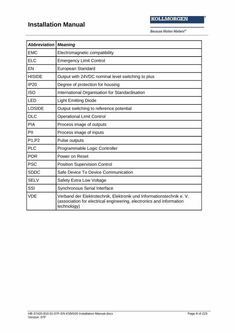
1.3 Abbreviations used
Abbreviation Meaning
AC Alternating voltage
IL Instruction list
ELIA Employer's liability insurance association
CLK Clock (cycle)
CPU Central Processing Unit
DC Direct voltage
DI1..DI14 Digital Input
DIN Deutsches Institut für Normung (German Institute for Standardization)
DO Digital Output
EMU Emergency Monitoring Unit
Installation Manual
HB-37420-810-01-07F-EN KSM100 Installation Manual.docx Page 8 of 223 Version: 07F
Abbreviation Meaning
EMC Electromagnetic compatibility
ELC Emergency Limit Control
EN European Standard
HISIDE Output with 24VDC nominal level switching to plus
IP20 Degree of protection for housing
ISO International Organisation for Standardisation
LED Light Emitting Diode
LOSIDE Output switching to reference potential
OLC Operational Limit Control
PIA Process image of outputs
PII Process image of inputs
P1,P2 Pulse outputs
PLC Programmable Logic Controller
POR Power on Reset
PSC Position Supervision Control
SDDC Safe Device To Device Communication
SELV Safety Extra Low Voltage
SSI Synchronous Serial Interface
VDE Verband der Elektrotechnik, Elektronik und Informationstechnik e. V. (association for electrical engineering, electronics and information technology)
Installation Manual
HB-37420-810-01-07F-EN KSM100 Installation Manual.docx Page 9 of 223 Version: 07F
2 Safety regulations
2.1 Intended use Devices of the KSM100 series are programmable fail-safe control system intended for the establishment of emergency shut-down features and functions. The devices are intended for use in
- EMERGENCY STOP facilities, - as safety component as defined by the EC machine directive 2006/42/EC, - as PES for risk reduction as defined by EN 61508, - in safety circuits acc. to EN 60204 and EN 60204-32, - as PES for functional safety as defined by EN 62061, - as SRP/CS as defined by EN 13849, - as device for establishing the safety functions acc. to EN 61800-5-2, - as logic unit for converting and processing signals in two-hand control acc. to EN 574.
2.2 General safety regulations
Safety note:
In order to avoid damage to persons and property only qualified personnel is entitled to work on the device. The term qualified personnel refers to persons who have successfully completed electrotechnical training and are fully familiar with the applicable rules and standards of electrical engineering. The qualified person must become familiar with the operating instructions (see IEC364, DIN VDE0100).
The qualified must have profound knowledge of the national accident prevention regulations
The use of the device must be strictly limited to the intended use as specified in the following list. The values of data listed under section “3.2 Characteristic device data” must also be observed.
The contents of this installation manual is restricted to the basic function of the device or its installation. The “Programming instructions KSM100” contains a more detailed description of the programming and re-parameterization of the devices. Exact knowledge and understanding of these instructions is mandatory for a new installation or modification of device functions or device parameters.
Commissioning (i.e. starting up the intended operation) is only permitted in strict compliance with the EMC-directive. The EMC-testing regulations EN55011:2007 + A2:2007 and EN 61000-6-2:2005 are used as basis.

Installation Manual
HB-37420-810-01-07F-EN KSM100 Installation Manual.docx Page 10 of 223 Version: 07F
Compliance with the conditions acc. to EN 60068-2-6 related to the values specified under “Technical characteristics” is mandatory for storage and transport.
The wiring and connecting instructions in chapter “Installation” must be strictly followed.
The applicable VDE-regulations and other special safety regulations of relevance for the application must be strictly followed.
Evidence of the configured monitoring functions as well as their parameters and links must be issued by means of a validation report.
The implementation of the module must be coordinated with the demands of the responsible acceptance testing authority (e.g. TÜV or ELIA).
Do not install or operate damaged products. Report damages immediately to the responsible forwarding agent.
Never open the housing and/or make unauthorized conversions.
Inputs and outputs for standard functions or digital and analog data transmitted via communication modules must not be used for safety relevant applications.
WARNING: Using our devices contrary to the rules and conditions specified hereunder can lead to injuries or fatalities as well as damage to connected devices and machines! This will also cause the loss of all warranty and compensation claims against Kollmorgen.

Installation Manual
HB-37420-810-01-07F-EN KSM100 Installation Manual.docx Page 11 of 223 Version: 07F
2.3 Operation and service
The module must always be de-energized before installation and removal, or before disconnecting signal lines. For this purpose all live supply lines to the device must be checked for safe isolation from supply When installing or removing the module appropriate measures must be applied to prevent electrostatic discharge to the externally arranged terminal and plug connections. Contact with such terminals should be reduced to a minimum and earthing should by means of e.g. an earthing strap should take place before and during these procedures.
2.4 Transport/storage
Information concerning transport, storage and proper handling must be strictly followed. The climate related specifications in chapter “Technical data” must be with complied.
Installation Manual
HB-37420-810-01-07F-EN KSM100 Installation Manual.docx Page 12 of 223 Version: 07F
3 Device types
The series KSM100 consists of - the basic devices KSM100-1/100-2/100-4 - the extension modules KSM121, KSM121-2, KSM122(A), KSM122-2(A), and KSM131
Basic devices
The KSM100 series represents a modular fail-safe control system. The device is freely programmable for reliable processing of both EMERGENCY STOP button, two-hand control, light grid, operation mode switch, etc., but also of drive related safety functions. Pre-configured modules for safety relevant signal pre-processing are available for a vast number of input devices. The same applies for safety functions serving the purpose of drive monitoring. Detailed information can be found in the programming manual.
The basic version of the device has 14 secure inputs and 3 shut-down channels, which can be extended to max. 130 inputs, 65 of which are secure I/O's.
Single encoder solutions (incl. TTL/HTL, SIN(COS, Proxi-Sw.) as well as dual encoder solutions (e.g. 2 x Inc.-TTL or SSI and Inc..HTL) are supported for reliable speed and/or position detection.
Extension modules:
Axis extension modules for the KSM100 series: KSM121, KSM121-2, KSM122(A), KSM122-2(A)
Digital I/O extension for the KSM100 series: KSM131. A maximum of 8 extension modules can be connected to a system. The extension module has 12 secure inputs, 10 secure I/O for optional configuration as input or output and 2 signal outputs.
Extension module for the transfer of diagnostic and status data to an imposed control by means of standard field bus.
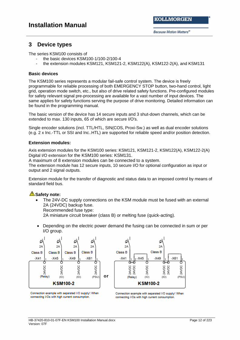
Safety note:
The 24V-DC supply connections on the KSM module must be fused with an external 2A (24VDC) backup fuse. Recommended fuse type: 2A miniature circuit breaker (class B) or melting fuse (quick-acting).
Depending on the electric power demand the fusing can be connected in sum or per I/O group.
Installation Manual
HB-37420-810-01-07F-EN KSM100 Installation Manual.docx Page 13 of 223 Version: 07F
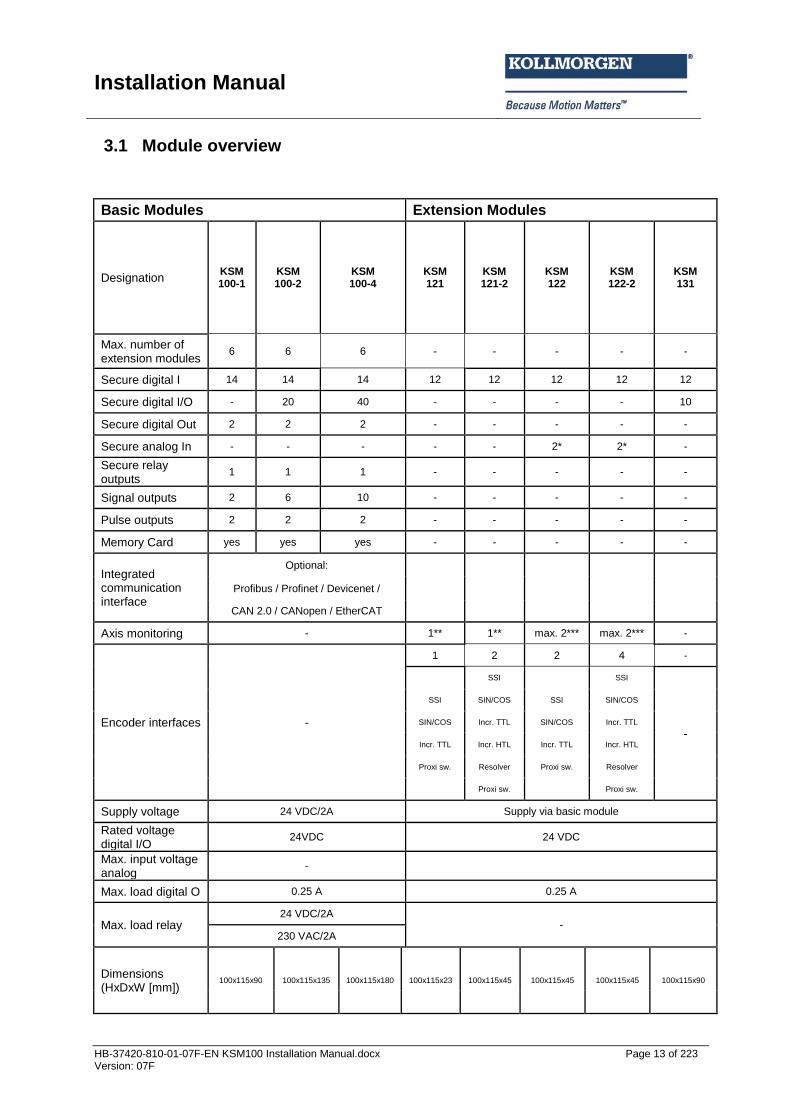
3.1 Module overview
Basic Modules Extension Modules
Designation KSM 100-1
KSM 100-2
KSM 100-4
KSM 121
KSM 121-2
KSM 122
KSM 122-2
KSM 131
Max. number of extension modules
6 6 6 - - - - -
Secure digital I 14 14 14 12 12 12 12 12
Secure digital I/O - 20 40 - - - - 10
Secure digital Out 2 2 2 - - - - -
Secure analog In - - - - - 2* 2* -
Secure relay outputs
1 1 1 - - - - -
Signal outputs 2 6 10 - - - - -
Pulse outputs 2 2 2 - - - - -
Memory Card yes yes yes - - - - -
Integrated communication interface
Optional:
Profibus / Profinet / Devicenet /
CAN 2.0 / CANopen / EtherCAT
Axis monitoring - 1** 1** max. 2*** max. 2*** -
Encoder interfaces -
1 2 2 4 -
SSI SSI
-
SSI SIN/COS SSI SIN/COS
SIN/COS Incr. TTL SIN/COS Incr. TTL
Incr. TTL Incr. HTL Incr. TTL Incr. HTL
Proxi sw. Resolver Proxi sw. Resolver
Proxi sw. Proxi sw.
Supply voltage 24 VDC/2A Supply via basic module
Rated voltage digital I/O
24VDC 24 VDC
Max. input voltage analog
-
Max. load digital O 0.25 A 0.25 A
Max. load relay 24 VDC/2A
- 230 VAC/2A
Dimensions (HxDxW [mm])
100x115x90 100x115x135 100x115x180 100x115x23 100x115x45 100x115x45 100x115x45 100x115x90

Installation Manual
HB-37420-810-01-07F-EN KSM100 Installation Manual.docx Page 14 of 223 Version: 07F
3.2 Characteristic data of device
3.2.1 Basic modules
3.2.1.1 System module KSM 100-1
Type designation Device design
Design of module with the following periphery: 14 digital inputs 2 digital outputs 1 digital output relay 2 signal outputs 2 pulse generator outputs
Characteristics of the module:
14 secure inputs, 3 shut-down channels, 1 of these a secure relay output and 2 secure signal outputs provided by the basic device
Extendable to max. 130 secure I/O and/or 12 secure axes by means of integrated backplane bus (connectors to snap on top-hat rail)
Logic diagram oriented programming by means of SafePLC-SW
Extensive library for pre-configured safety sensors and operator controls
Complete speed and position related safety functions for drive monitoring in accordance with DIN EN 61800 integrated in firmware
Three-dimensional functions for secure speed and area monitoring possible
Parameter management for extension modules in the basic device
Cross-shorting monitoring
Possibility of contact multiplication or contact amplification by means of external contactors in connection with integrated monitoring
Extensive diagnostics functions integrated in FW
Encoded status display via 7-segment display and status LEDs in front panel
Quit-/Start-/Reset buttons operable in front panel
Optionally with connection to superimposed Master by means of standard field bus communication via CAN-Bus 2.0 interface, CANopen, PROFIBUS, PROFINET, EtherCAT, DeviceNet, or secure field bus communication by means of PROFIsafe V 2.0 or FSoE.
Installation Manual
HB-37420-810-01-07F-EN KSM100 Installation Manual.docx Page 15 of 223 Version: 07F
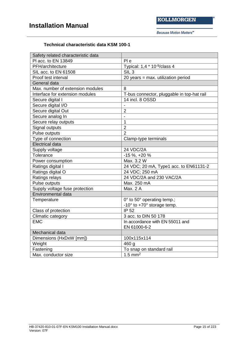
Technical characteristic data KSM 100-1
Safety related characteristic data
Pl acc. to EN 13849 Pl e
PFH/architecture Typical: 1,4 * 10-9/class 4
SIL acc. to EN 61508 SIL 3
Proof test interval 20 years = max. utilization period
General data
Max. number of extension modules 8
Interface for extension modules T-bus connector, pluggable in top-hat rail
Secure digital I 14 incl. 8 OSSD
Secure digital I/O -
Secure digital Out 2
Secure analog In -
Secure relay outputs 1
Signal outputs 2
Pulse outputs 2
Type of connection Clamp-type terminals
Electrical data
Supply voltage 24 VDC/2A
Tolerance -15 %, +20 %
Power consumption Max. 3.2 W
Ratings digital I 24 VDC; 20 mA, Type1 acc. to EN61131-2
Ratings digital O 24 VDC; 250 mA
Ratings relays 24 VDC/2A and 230 VAC/2A
Pulse outputs Max. 250 mA
Supply voltage fuse protection Max. 2 A
Environmental data
Temperature 0° to 50° operating temp.;
-10° to +70° storage temp.
Class of protection IP 52
Climatic category 3 acc. to DIN 50 178
EMC In accordance with EN 55011 and
EN 61000-6-2
Mechanical data
Dimensions (HxDxW [mm]) 100x115x114
Weight 460 g
Fastening To snap on standard rail
Max. conductor size 1.5 mm2

Installation Manual
HB-37420-810-01-07F-EN KSM100 Installation Manual.docx Page 16 of 223 Version: 07F
3.2.1.2 System module KSM 100-2
Type designation Device design
Design of module with the following periphery: 20 secure digital I/O 14 digital inputs 2 pulse generator outputs 1 digital output relay 2 digital outputs LOSIDE 2 digital outputs HISIDE 6 signal outputs
Characteristics of the module:
20 secure I/O – configurable as input or output, 14 secure inputs, 3 shut-down channels, 1 of these a secure relay output and 6 signal outputs provided by the basic device
Extendable to max. 130 secure I/O and/or 12 secure axes by means of integrated backplane bus (connectors to snap on top-hat rail)
Logic diagram oriented programming by means of SafePLC-SW
Extensive library for pre-configured safety sensors and operator controls
Complete speed and position related safety functions for drive monitoring in accordance with DIN EN 61800 integrated in firmware
Three-dimensional functions for secure speed and area monitoring possible
Parameter management for extension modules in the basic device
Cross-shorting monitoring
Possibility of contact multiplication or contact amplification by means of external contactors in connection with integrated monitoring
Extensive diagnostics functions integrated in FW
Encoded status display via 7-segment display and status LEDs in front panel
Quit-/Start-/Reset buttons operable in front panel
Optionally with connection to superimposed Master by means of standard field bus communication via CAN-Bus 2.0 interface, CANopen, PROFIBUS, PROFINET, EtherCAT, DeviceNet, or secure field bus communication by means of PROFIsafe V 2.0 or FSoE.
Installation Manual
HB-37420-810-01-07F-EN KSM100 Installation Manual.docx Page 17 of 223 Version: 07F
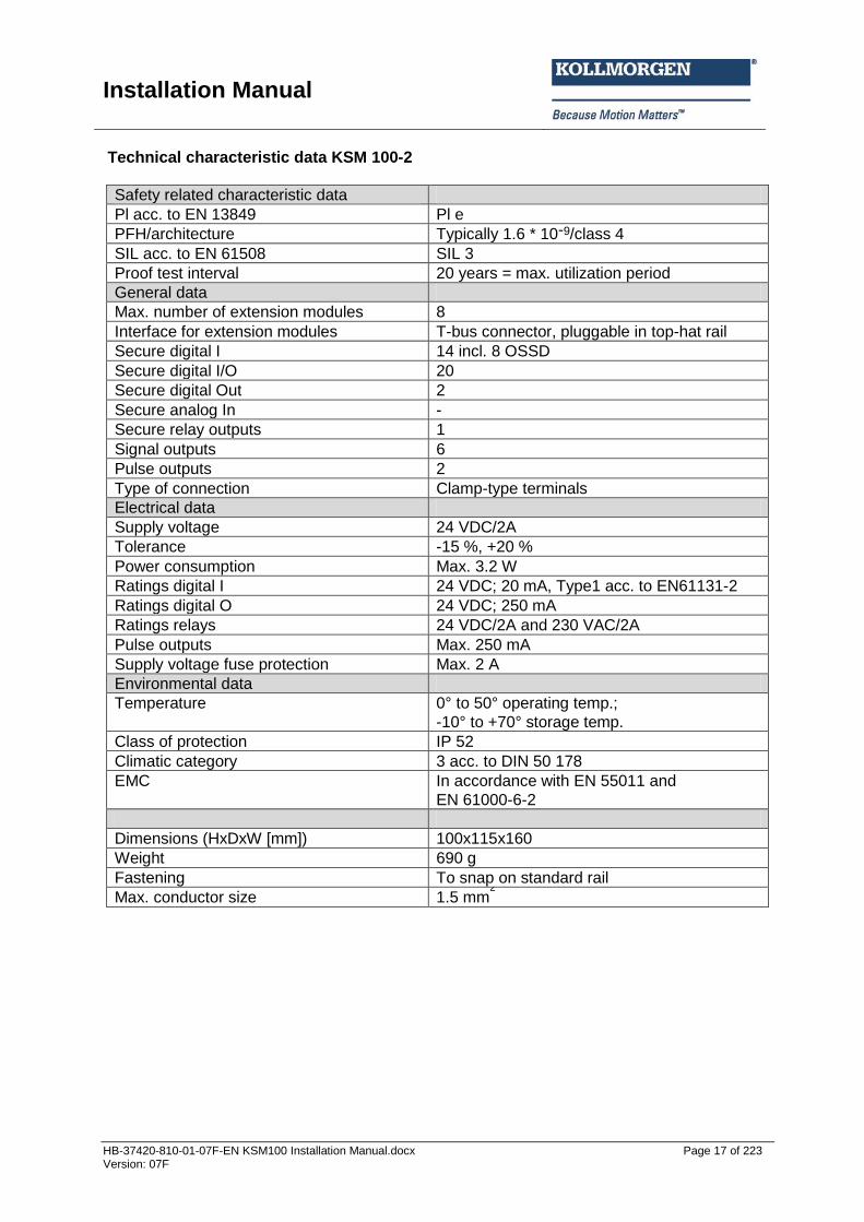
Technical characteristic data KSM 100-2
Safety related characteristic data
Pl acc. to EN 13849 Pl e
PFH/architecture Typically 1.6 * 10-9/class 4
SIL acc. to EN 61508 SIL 3
Proof test interval 20 years = max. utilization period
General data
Max. number of extension modules 8
Interface for extension modules T-bus connector, pluggable in top-hat rail
Secure digital I 14 incl. 8 OSSD
Secure digital I/O 20
Secure digital Out 2
Secure analog In -
Secure relay outputs 1
Signal outputs 6
Pulse outputs 2
Type of connection Clamp-type terminals
Electrical data
Supply voltage 24 VDC/2A
Tolerance -15 %, +20 %
Power consumption Max. 3.2 W
Ratings digital I 24 VDC; 20 mA, Type1 acc. to EN61131-2
Ratings digital O 24 VDC; 250 mA
Ratings relays 24 VDC/2A and 230 VAC/2A
Pulse outputs Max. 250 mA
Supply voltage fuse protection Max. 2 A
Environmental data
Temperature 0° to 50° operating temp.;
-10° to +70° storage temp.
Class of protection IP 52
Climatic category 3 acc. to DIN 50 178
EMC In accordance with EN 55011 and
EN 61000-6-2
Dimensions (HxDxW [mm]) 100x115x160
Weight 690 g
Fastening To snap on standard rail
Max. conductor size 1.5 mm2

Installation Manual
HB-37420-810-01-07F-EN KSM100 Installation Manual.docx Page 18 of 223 Version: 07F
3.2.1.3 System module KSM 100-4
Type designation Device design
Design of module with the following periphery: 40 secure digital I/O 14 digital inputs 2 digital outputs 1 digital output relay 10 signal outputs 2 pulse generator outputs
Characteristics of the module:
40 secure I/O – configurable as input or output, 14 secure inputs, 3 shut-down channels, 1 of these a secure relay output and 10 signal outputs provided by the basic device
Extendable to max. 130 secure I/O and/or 12 secure axes by means of integrated backplane bus (connectors to snap on top-hat rail)
Logic diagram oriented programming by means of SafePLC-SW
Extensive library for pre-configured safety sensors and operator controls
Complete speed and position related safety functions for drive monitoring in accordance with DIN EN 61800 integrated in firmware
Three-dimensional functions for secure speed and area monitoring possible
Parameter management for extension modules in the basic device
Cross-shorting monitoring
Possibility of contact multiplication or contact amplification by means of external contactors in connection with integrated monitoring
Extensive diagnostics functions integrated in FW
Encoded status display via 7-segment display and status LEDs in front panel
Quit-/Start-/Reset buttons operable in front panel
Optionally with connection to superimposed Master by means of standard field bus communication via CAN-Bus 2.0 interface, CANopen, PROFIBUS, PROFINET, EtherCAT, DeviceNet, or secure field bus communication by means of PROFIsafe V 2.0 or FSoE.

Installation Manual
HB-37420-810-01-07F-EN KSM100 Installation Manual.docx Page 19 of 223 Version: 07F
Technical characteristic data KSM 100-4
Safety related characteristic data
Pl acc. to EN 13849 Pl e
PFH/architecture Typical: 1.7 * 10-9/class 4
SIL acc. to EN 61508 SIL 3
Proof test interval 20 years = max. utilization period
General data
Max. number of extension modules 8
Interface for extension modules T-bus connector, pluggable in top-hat rail
Secure digital I 14 incl. 8 OSSD
Secure digital I/O 40
Secure digital Out 2
Secure analog In -
Secure relay outputs 1
Signal outputs 10
Pulse outputs 2
Type of connection Clamp-type terminals
Electrical data
Supply voltage 24 VDC/2A
Tolerance -15 %, +20 %
Power consumption Max. 3.2 W
Ratings digital I 24 VDC; 20 mA, Type1 acc. to EN61131-2
Ratings digital O 24 VDC; 250 mA
Ratings relays 24 VDC/2A and 230 VAC/2A
Pulse outputs Max. 250 mA
Supply voltage fuse protection Max. 2 A
Environmental data
Temperature 0° to 50° operating temp.;
-10° to +70° storage temp.
Class of protection IP 52
Climatic category 3 acc. to DIN 50 178
EMC In accordance with EN 55011 and
EN 61000-6-2
Dimensions (HxDxW [mm]) 100x115x205
Weight 920 g
Fastening To snap on standard rail
Max. conductor size 1,5 mm2

Installation Manual
HB-37420-810-01-07F-EN KSM100 Installation Manual.docx Page 20 of 223 Version: 07F
3.2.2 Extension modules
3.2.2.1 Extension module KSM 121
Type designation Device design
Design of module with the following periphery: 12 digital inputs 1 axis
Characteristics of the module:
Parametrizable encoder interface for 1x incr.-TTL, SIN/COS and 1x HTL via terminal connection
Cross-shorting monitoring by means of pulse outputs on the basic device
Extensive diagnostics functions integrated in FW
Power supply via basic module
Installation Manual
HB-37420-810-01-07F-EN KSM100 Installation Manual.docx Page 21 of 223 Version: 07F
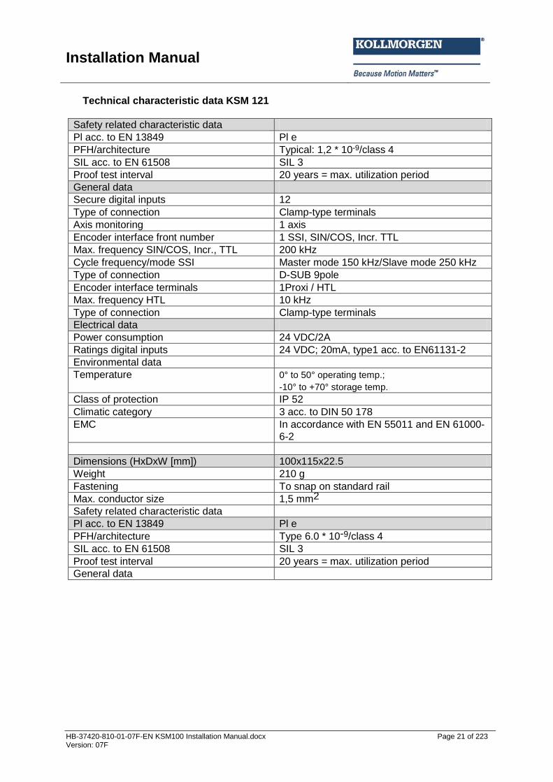
Technical characteristic data KSM 121
Safety related characteristic data
Pl acc. to EN 13849 Pl e
PFH/architecture Typical: 1,2 * 10-9/class 4
SIL acc. to EN 61508 SIL 3
Proof test interval 20 years = max. utilization period
General data
Secure digital inputs 12
Type of connection Clamp-type terminals
Axis monitoring 1 axis
Encoder interface front number 1 SSI, SIN/COS, Incr. TTL
Max. frequency SIN/COS, Incr., TTL 200 kHz
Cycle frequency/mode SSI Master mode 150 kHz/Slave mode 250 kHz
Type of connection D-SUB 9pole
Encoder interface terminals 1Proxi / HTL
Max. frequency HTL 10 kHz
Type of connection Clamp-type terminals
Electrical data
Power consumption 24 VDC/2A
Ratings digital inputs 24 VDC; 20mA, type1 acc. to EN61131-2
Environmental data
Temperature 0° to 50° operating temp.;
-10° to +70° storage temp.
Class of protection IP 52
Climatic category 3 acc. to DIN 50 178
EMC In accordance with EN 55011 and EN 61000-
6-2
Dimensions (HxDxW [mm]) 100x115x22.5
Weight 210 g
Fastening To snap on standard rail
Max. conductor size 1,5 mm2
Safety related characteristic data
Pl acc. to EN 13849 Pl e
PFH/architecture Type 6.0 * 10-9/class 4
SIL acc. to EN 61508 SIL 3
Proof test interval 20 years = max. utilization period
General data

Installation Manual
HB-37420-810-01-07F-EN KSM100 Installation Manual.docx Page 22 of 223 Version: 07F
3.2.2.2 Extension module KSM 121-2
Type designation Device design
Design of module with the following periphery: 12 digital inputs 2 axes 1 encoder solution
Characteristics of the module:
Parametrizable encoder interface for 2x Incr, SIN/COS,SSI, HTL and 1x Resolver
Cross-shorting monitoring by means of pulse outputs on the basic device
Extensive diagnostics functions integrated in FW
Power supply via basic module
Installation Manual
HB-37420-810-01-07F-EN KSM100 Installation Manual.docx Page 23 of 223 Version: 07F
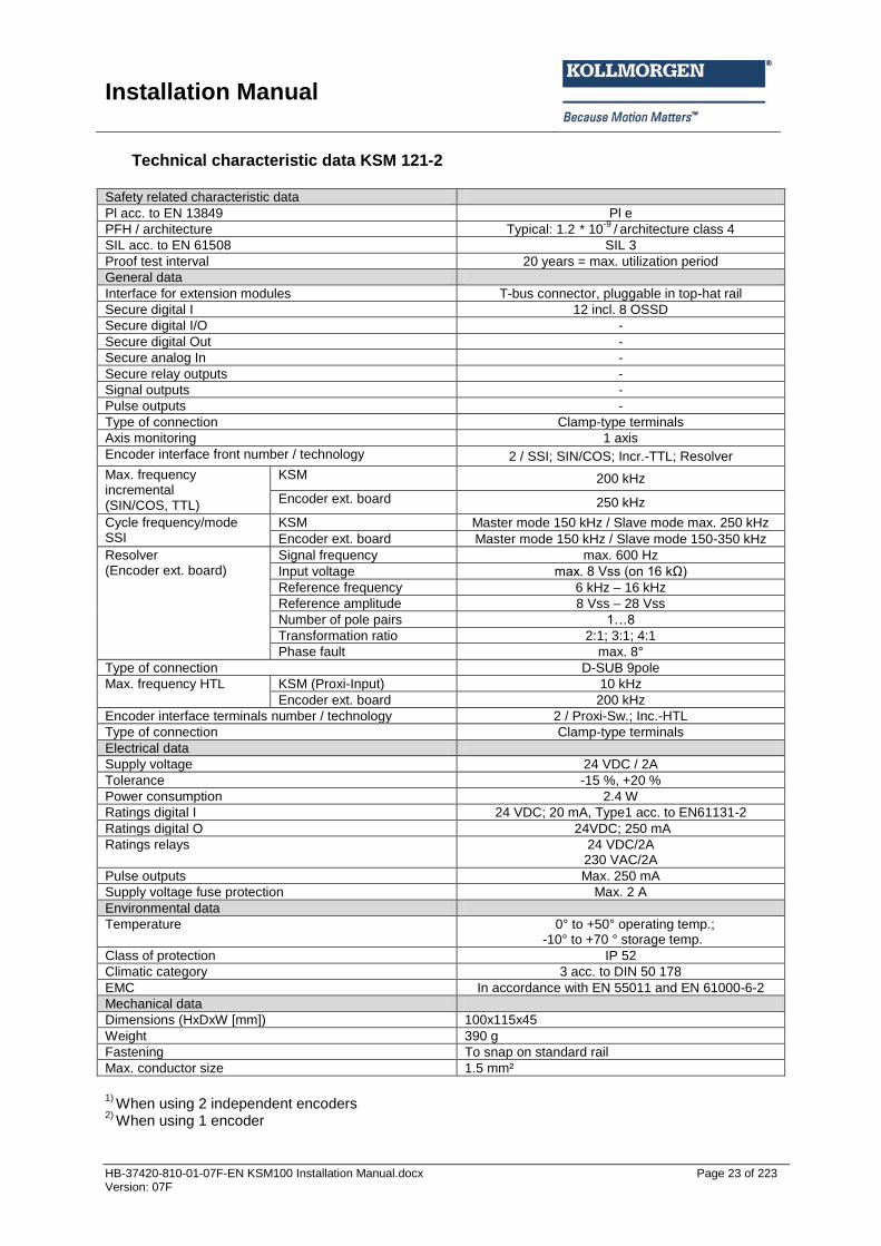
Technical characteristic data KSM 121-2 Safety related characteristic data
Pl acc. to EN 13849 Pl e
PFH / architecture Typical: 1.2 * 10-9
/ architecture class 4
SIL acc. to EN 61508 SIL 3
Proof test interval 20 years = max. utilization period
General data
Interface for extension modules T-bus connector, pluggable in top-hat rail
Secure digital I 12 incl. 8 OSSD
Secure digital I/O -
Secure digital Out -
Secure analog In -
Secure relay outputs -
Signal outputs -
Pulse outputs -
Type of connection Clamp-type terminals
Axis monitoring 1 axis
Encoder interface front number / technology 2 / SSI; SIN/COS; Incr.-TTL; Resolver
Max. frequency incremental (SIN/COS, TTL)
KSM 200 kHz
Encoder ext. board 250 kHz
Cycle frequency/mode SSI
KSM Master mode 150 kHz / Slave mode max. 250 kHz
Encoder ext. board Master mode 150 kHz / Slave mode 150-350 kHz
Resolver (Encoder ext. board)
Signal frequency max. 600 Hz
Input voltage max. 8 Vss (on 16 kΩ)
Reference frequency 6 kHz – 16 kHz
Reference amplitude 8 Vss – 28 Vss
Number of pole pairs 1…8
Transformation ratio 2:1; 3:1; 4:1
Phase fault max. 8°
Type of connection D-SUB 9pole
Max. frequency HTL KSM (Proxi-Input) 10 kHz
Encoder ext. board 200 kHz
Encoder interface terminals number / technology 2 / Proxi-Sw.; Inc.-HTL
Type of connection Clamp-type terminals
Electrical data
Supply voltage 24 VDC / 2A
Tolerance -15 %, +20 %
Power consumption 2.4 W
Ratings digital I 24 VDC; 20 mA, Type1 acc. to EN61131-2
Ratings digital O 24VDC; 250 mA
Ratings relays 24 VDC/2A 230 VAC/2A
Pulse outputs Max. 250 mA
Supply voltage fuse protection Max. 2 A
Environmental data
Temperature 0° to +50° operating temp.; -10° to +70 ° storage temp.
Class of protection IP 52
Climatic category 3 acc. to DIN 50 178
EMC In accordance with EN 55011 and EN 61000-6-2
Mechanical data
Dimensions (HxDxW [mm]) 100x115x45
Weight 390 g
Fastening To snap on standard rail
Max. conductor size 1.5 mm²
1)
When using 2 independent encoders 2)
When using 1 encoder

Installation Manual
HB-37420-810-01-07F-EN KSM100 Installation Manual.docx Page 24 of 223 Version: 07F
3.2.2.3 Extension module KSM 122 (A)
Type designation Device design
Design of module with the following periphery: 12 digital inputs 2 axes 1 encoder solution
Characteristics of the module:
Parametrizable encoder interface for 1 x Incr-TTL/SIN-COS/SSI in front panel and 1 x HTL via terminal connection
12 secure inputs
Optionally 2 secure analog inputs (option “A”)
Cross-shorting monitoring by means of pulse outputs on the basic device
Extensive diagnostics functions integrated in FW
Power supply via basic module
Installation Manual
HB-37420-810-01-07F-EN KSM100 Installation Manual.docx Page 25 of 223 Version: 07F
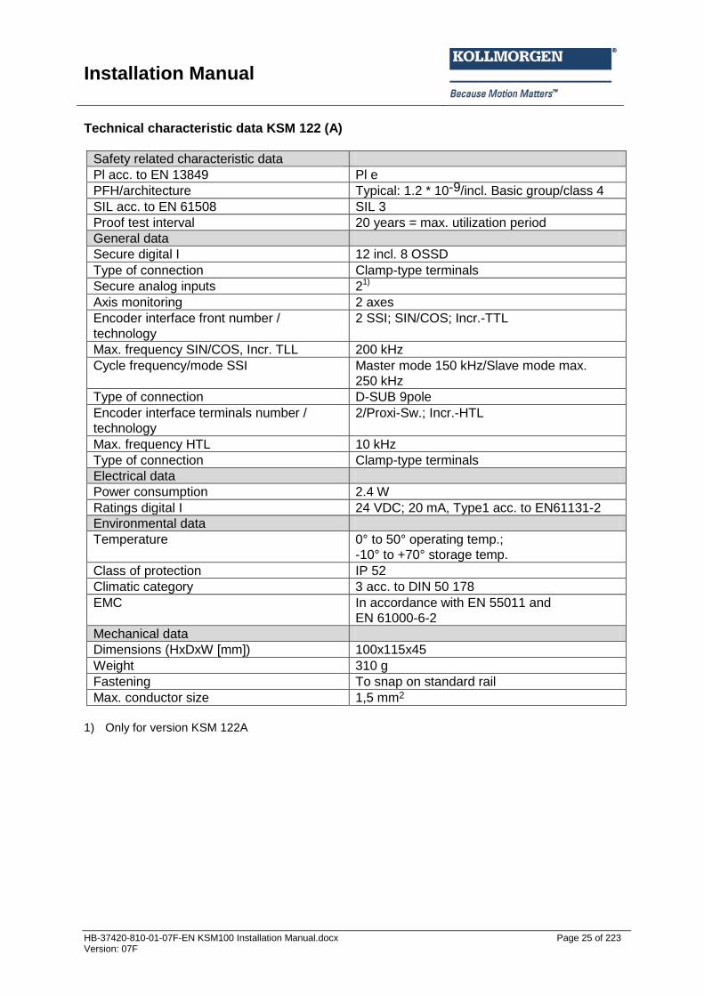
Technical characteristic data KSM 122 (A)
Safety related characteristic data
Pl acc. to EN 13849 Pl e
PFH/architecture Typical: 1.2 * 10-9/incl. Basic group/class 4
SIL acc. to EN 61508 SIL 3
Proof test interval 20 years = max. utilization period
General data
Secure digital I 12 incl. 8 OSSD
Type of connection Clamp-type terminals
Secure analog inputs 21)
Axis monitoring 2 axes
Encoder interface front number /
technology
2 SSI; SIN/COS; Incr.-TTL
Max. frequency SIN/COS, Incr. TLL 200 kHz
Cycle frequency/mode SSI Master mode 150 kHz/Slave mode max.
250 kHz
Type of connection D-SUB 9pole
Encoder interface terminals number /
technology
2/Proxi-Sw.; Incr.-HTL
Max. frequency HTL 10 kHz
Type of connection Clamp-type terminals
Electrical data
Power consumption 2.4 W
Ratings digital I 24 VDC; 20 mA, Type1 acc. to EN61131-2
Environmental data
Temperature 0° to 50° operating temp.;
-10° to +70° storage temp.
Class of protection IP 52
Climatic category 3 acc. to DIN 50 178
EMC In accordance with EN 55011 and
EN 61000-6-2
Mechanical data
Dimensions (HxDxW [mm]) 100x115x45
Weight 310 g
Fastening To snap on standard rail
Max. conductor size 1,5 mm2
1) Only for version KSM 122A

Installation Manual
HB-37420-810-01-07F-EN KSM100 Installation Manual.docx Page 26 of 223 Version: 07F
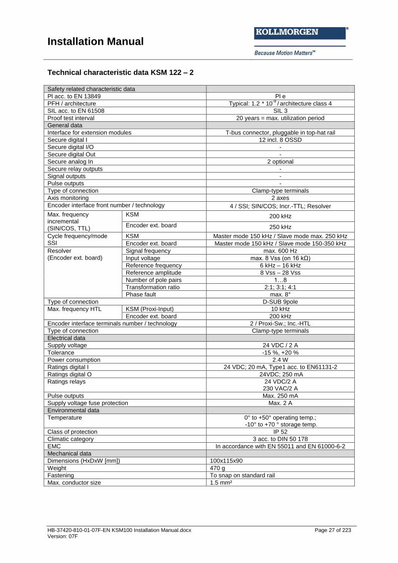
3.2.2.4 Extension module KSM 122-2
Type designation Device design
Design of module with the following periphery: 12 digital inputs 2 axes 2 encoder solutions
Characteristics of the module
Parametrizable encoder interface for 2 x 2 x Incr-TTL/SIN-COS/SSI and 2 x HTL/Resolver
12 secure inputs
Cross-shorting monitoring by means of pulse outputs on the basic device
Extensive diagnostics functions integrated in FW
Power supply via basic module
Installation Manual
HB-37420-810-01-07F-EN KSM100 Installation Manual.docx Page 27 of 223 Version: 07F
Technical characteristic data KSM 122 – 2 Safety related characteristic data
Pl acc. to EN 13849 Pl e
PFH / architecture Typical: 1.2 * 10-9
/ architecture class 4
SIL acc. to EN 61508 SIL 3
Proof test interval 20 years = max. utilization period
General data
Interface for extension modules T-bus connector, pluggable in top-hat rail
Secure digital I 12 incl. 8 OSSD
Secure digital I/O -
Secure digital Out -
Secure analog In 2 optional
Secure relay outputs -
Signal outputs -
Pulse outputs -
Type of connection Clamp-type terminals
Axis monitoring 2 axes
Encoder interface front number / technology 4 / SSI; SIN/COS; Incr.-TTL; Resolver
Max. frequency incremental (SIN/COS, TTL)
KSM 200 kHz
Encoder ext. board 250 kHz
Cycle frequency/mode SSI
KSM Master mode 150 kHz / Slave mode max. 250 kHz
Encoder ext. board Master mode 150 kHz / Slave mode 150-350 kHz
Resolver (Encoder ext. board)
Signal frequency max. 600 Hz
Input voltage max. 8 Vss (on 16 kΩ)
Reference frequency 6 kHz – 16 kHz
Reference amplitude 8 Vss – 28 Vss
Number of pole pairs 1…8
Transformation ratio 2:1; 3:1; 4:1
Phase fault max. 8°
Type of connection D-SUB 9pole
Max. frequency HTL KSM (Proxi-Input) 10 kHz
Encoder ext. board 200 kHz
Encoder interface terminals number / technology 2 / Proxi-Sw.; Inc.-HTL
Type of connection Clamp-type terminals
Electrical data
Supply voltage 24 VDC / 2 A
Tolerance -15 %, +20 %
Power consumption 2.4 W
Ratings digital I 24 VDC; 20 mA, Type1 acc. to EN61131-2
Ratings digital O 24VDC; 250 mA
Ratings relays 24 VDC/2 A 230 VAC/2 A
Pulse outputs Max. 250 mA
Supply voltage fuse protection Max. 2 A
Environmental data
Temperature 0° to +50° operating temp.; -10° to +70 ° storage temp.
Class of protection IP 52
Climatic category 3 acc. to DIN 50 178
EMC In accordance with EN 55011 and EN 61000-6-2
Mechanical data
Dimensions (HxDxW [mm]) 100x115x90
Weight 470 g
Fastening To snap on standard rail
Max. conductor size 1.5 mm²
Installation Manual
HB-37420-810-01-07F-EN KSM100 Installation Manual.docx Page 28 of 223 Version: 07F
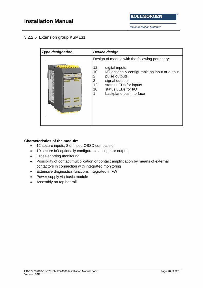
3.2.2.5 Extension group KSM131
Type designation Device design
Design of module with the following periphery: 12 digital inputs 10 I/O optionally configurable as input or output 2 pulse outputs 2 signal outputs 12 status LEDs for inputs 10 status LEDs for I/O 1 backplane bus interface
Characteristics of the module:
12 secure inputs; 8 of these OSSD compatible
10 secure I/O optionally configurable as input or output,
Cross-shorting monitoring
Possibility of contact multiplication or contact amplification by means of external
contactors in connection with integrated monitoring
Extensive diagnostics functions integrated in FW
Power supply via basic module
Assembly on top hat rail
Installation Manual
HB-37420-810-01-07F-EN KSM100 Installation Manual.docx Page 29 of 223 Version: 07F
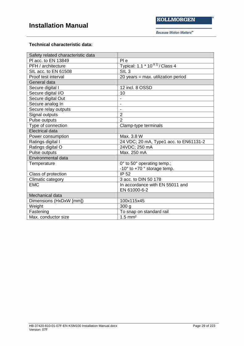
Technical characteristic data:
Safety related characteristic data
Pl acc. to EN 13849 Pl e
PFH / architecture Typical: 1.1 * 10-9 1) / Class 4
SIL acc. to EN 61508 SIL 3
Proof test interval 20 years = max. utilization period
General data
Secure digital I 12 incl. 8 OSSD
Secure digital I/O 10
Secure digital Out -
Secure analog In -
Secure relay outputs -
Signal outputs 2
Pulse outputs 2
Type of connection Clamp-type terminals
Electrical data
Power consumption Max. 3.8 W
Ratings digital I 24 VDC; 20 mA, Type1 acc. to EN61131-2
Ratings digital O 24VDC; 250 mA
Pulse outputs Max. 250 mA
Environmental data
Temperature 0° to 50° operating temp.; -10° to +70 ° storage temp.
Class of protection IP 52
Climatic category 3 acc. to DIN 50 178
EMC In accordance with EN 55011 and EN 61000-6-2
Mechanical data
Dimensions (HxDxW [mm]) 100x115x45
Weight 300 g
Fastening To snap on standard rail
Max. conductor size 1.5 mm²

Installation Manual
HB-37420-810-01-07F-EN KSM100 Installation Manual.docx Page 30 of 223 Version: 07F
3.3 Identification The type plate is located on the left side wall of the module and contains the following information: Type designation Part number Serial number Identification of hardware release Identification of software release Safety category Input characteristics Output characteristics Date of manufacture (week/year)
3.3.1 Basic device
Type plate KSM100-1 (image enlarged)
3.3.2 Extension device
Type plate KSM121(image enlarged)
Installation Manual
HB-37420-810-01-07F-EN KSM100 Installation Manual.docx Page 31 of 223 Version: 07F
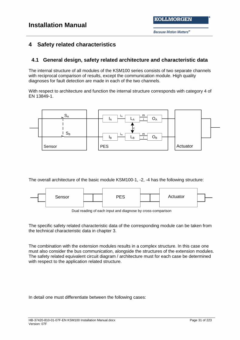
4 Safety related characteristics
4.1 General design, safety related architecture and characteristic data The internal structure of all modules of the KSM100 series consists of two separate channels with reciprocal comparison of results, except the communication module. High quality diagnoses for fault detection are made in each of the two channels. With respect to architecture and function the internal structure corresponds with category 4 of EN 13849-1.
IA OALA
IB OBLB
m
m
i
i
c
im
im
Sensor PES Aktuator
SA
SB
The overall architecture of the basic module KSM100-1, -2, -4 has the following structure:
Sensor PES Aktuator
Dual reading of each input and diagnose by cross-comparison The specific safety related characteristic data of the corresponding module can be taken from the technical characteristic data in chapter 3. The combination with the extension modules results in a complex structure. In this case one must also consider the bus communication, alongside the structures of the extension modules. The safety related equivalent circuit diagram / architecture must for each case be determined with respect to the application related structure. In detail one must differentiate between the following cases:
Actuator PES Sensor
Actuator
Installation Manual
HB-37420-810-01-07F-EN KSM100 Installation Manual.docx Page 32 of 223 Version: 07F
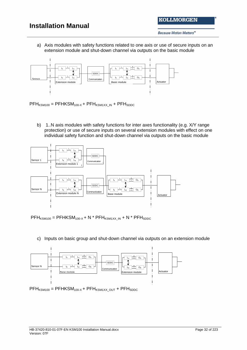
a) Axis modules with safety functions related to one axis or use of secure inputs on an extension module and shut-down channel via outputs on the basic module
IA OALA
IB OBLB
m
m
i
i
c
im
im
Basisbaugruppe Aktuator
IA LA
IB LB
c
im
im
Erweiterungsbaugruppe
SDDC
Kommunikation
SMX100-System
Sensor
PFHKSM100 = PFHKSM100-X + PFHKSM1XX_IN + PFHSDDC
b) 1..N axis modules with safety functions for inter axes functionality (e.g. X/Y range protection) or use of secure inputs on several extension modules with effect on one individual safety function and shut-down channel via outputs on the basic module
IA OALA
IB OBLB
m
m
i
i
c
im
im
Basisbaugruppe Aktuator
IA LA
IB LB
c
im
im
Erweiterungsbaugruppe N
SDDC
Kommunikation
SMX100-System
Sensor N
IA LA
IB LB
c
im
im
Erweiterungsbaugruppe 1
SDDC
KommunikationSensor 1
PFHKSM100 = PFHKSM100-X + N * PFHKSM1XX_IN + N * PFHSDDC
c) Inputs on basic group and shut-down channel via outputs on an extension module
IA OALA
IB OBLB
m
m
i
i
c
im
im
Basisbaugruppe Aktuator
SMX100-System
Sensor N
SDDC
Kommunikation
OALA
OBLB
m
m
i
i
c
Erweiterungsbaugruppe
PFHKSM100 = PFHKSM100-X + PFHKSM1XX_OUT + PFHSDDC
Sensor 1 Communication
Extension module 1
Sensor N
Base module Extension module N Communication
Actuator
Sensor Communication
Extension module Basic module Actuator
Sensor N Communication
Extension module Base module Actuator
Installation Manual
HB-37420-810-01-07F-EN KSM100 Installation Manual.docx Page 33 of 223 Version: 07F
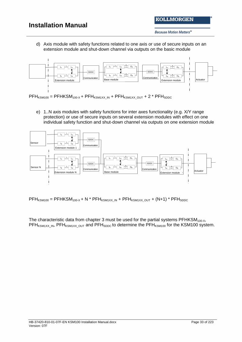
d) Axis module with safety functions related to one axis or use of secure inputs on an extension module and shut-down channel via outputs on the basic module
IA OALA
IB OBLB
m
m
i
i
c
im
im
Basisbaugruppe Aktuator
IA LA
IB LB
c
im
im
Erweiterungsbaugruppe
SDDC
Kommunikation
SMX100-System
SDDC
Kommunikation
OALA
OBLB
m
m
i
i
c
Erweiterungsbaugruppe
PFHKSM100 = PFHKSM100-X + PFHKSM1XX_IN + PFHKSM1XX_OUT + 2 * PFHSDDC
e) 1..N axis modules with safety functions for inter axes functionality (e.g. X/Y range protection) or use of secure inputs on several extension modules with effect on one individual safety function and shut-down channel via outputs on one extension module
IA OALA
IB OBLB
m
m
i
i
c
im
im
Basisbaugruppe Aktuator
IA LA
IB LB
c
im
im
Erweiterungsbaugruppe N
SDDC
Kommunikation
SMX100-System
Sensor N
SDDC
Kommunikation
OALA
OBLB
m
m
i
i
c
Erweiterungsbaugruppe
IA LA
IB LB
c
im
im
Erweiterungsbaugruppe 1
SDDC
KommunikationSensor 1
PFHKSM100 = PFHKSM100-X + N * PFHKSM1XX_IN + PFHKSM1XX_OUT + (N+1) * PFHSDDC The characteristic data from chapter 3 must be used for the partial systems PFHKSM100-X, PFHKSM1XX_IN, PFHKSM1XX_OUT and PFHSDDC to determine the PFHKSM100 for the KSM100 system.
Sensor N
Communication Extension module Base module Actuator Extension module
Communication
Communication Extension module 1
Base module Actuator Extension module
Communication Communication
Extension module N
Sensor
Installation Manual
HB-37420-810-01-07F-EN KSM100 Installation Manual.docx Page 34 of 223 Version: 07F
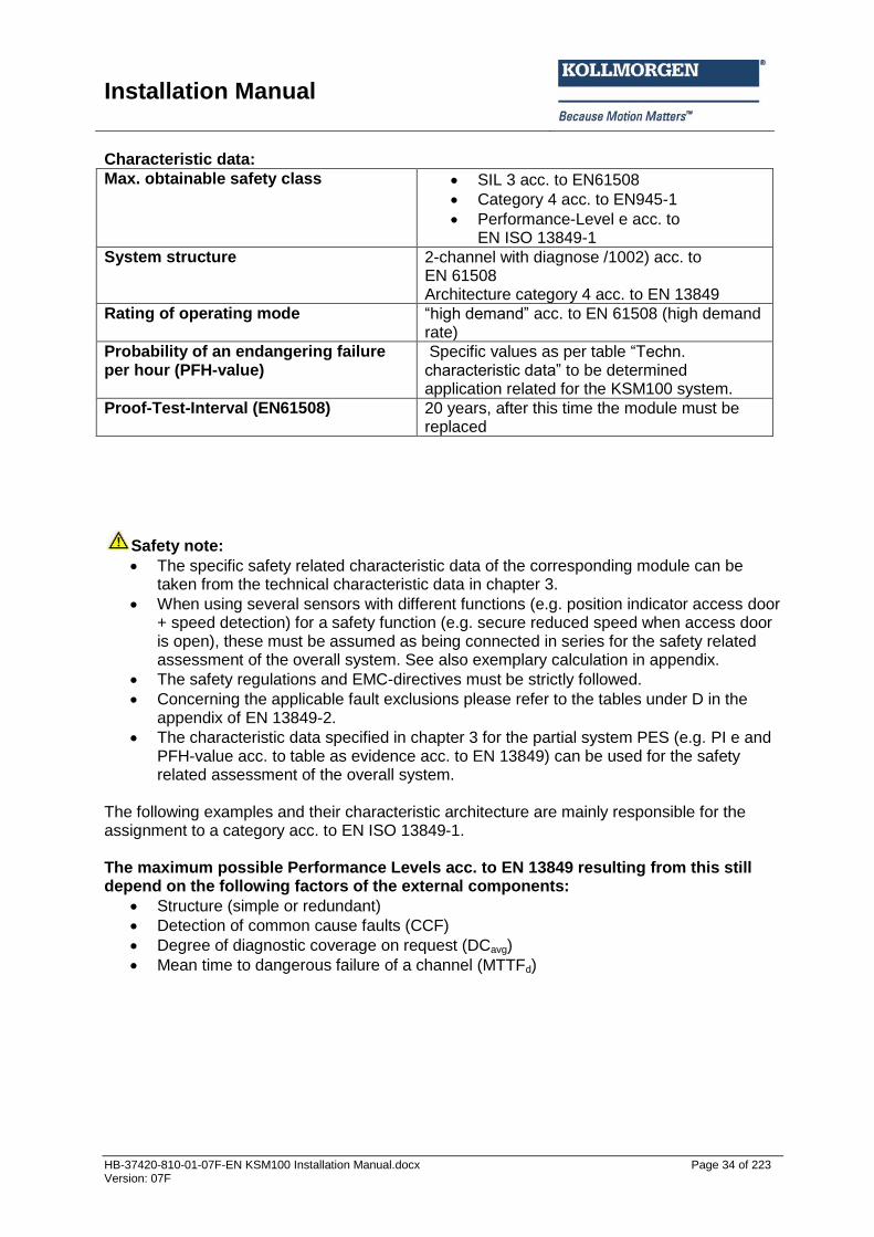
Characteristic data:
Max. obtainable safety class SIL 3 acc. to EN61508
Category 4 acc. to EN945-1
Performance-Level e acc. to EN ISO 13849-1
System structure 2-channel with diagnose /1002) acc. to EN 61508 Architecture category 4 acc. to EN 13849
Rating of operating mode “high demand” acc. to EN 61508 (high demand rate)
Probability of an endangering failure per hour (PFH-value)
Specific values as per table “Techn. characteristic data” to be determined application related for the KSM100 system.
Proof-Test-Interval (EN61508) 20 years, after this time the module must be replaced
Safety note:
The specific safety related characteristic data of the corresponding module can be taken from the technical characteristic data in chapter 3.
When using several sensors with different functions (e.g. position indicator access door + speed detection) for a safety function (e.g. secure reduced speed when access door is open), these must be assumed as being connected in series for the safety related assessment of the overall system. See also exemplary calculation in appendix.
The safety regulations and EMC-directives must be strictly followed.
Concerning the applicable fault exclusions please refer to the tables under D in the appendix of EN 13849-2.
The characteristic data specified in chapter 3 for the partial system PES (e.g. PI e and PFH-value acc. to table as evidence acc. to EN 13849) can be used for the safety related assessment of the overall system.
The following examples and their characteristic architecture are mainly responsible for the assignment to a category acc. to EN ISO 13849-1. The maximum possible Performance Levels acc. to EN 13849 resulting from this still depend on the following factors of the external components:
Structure (simple or redundant)
Detection of common cause faults (CCF)
Degree of diagnostic coverage on request (DCavg)
Mean time to dangerous failure of a channel (MTTFd)
Installation Manual
HB-37420-810-01-07F-EN KSM100 Installation Manual.docx Page 35 of 223 Version: 07F
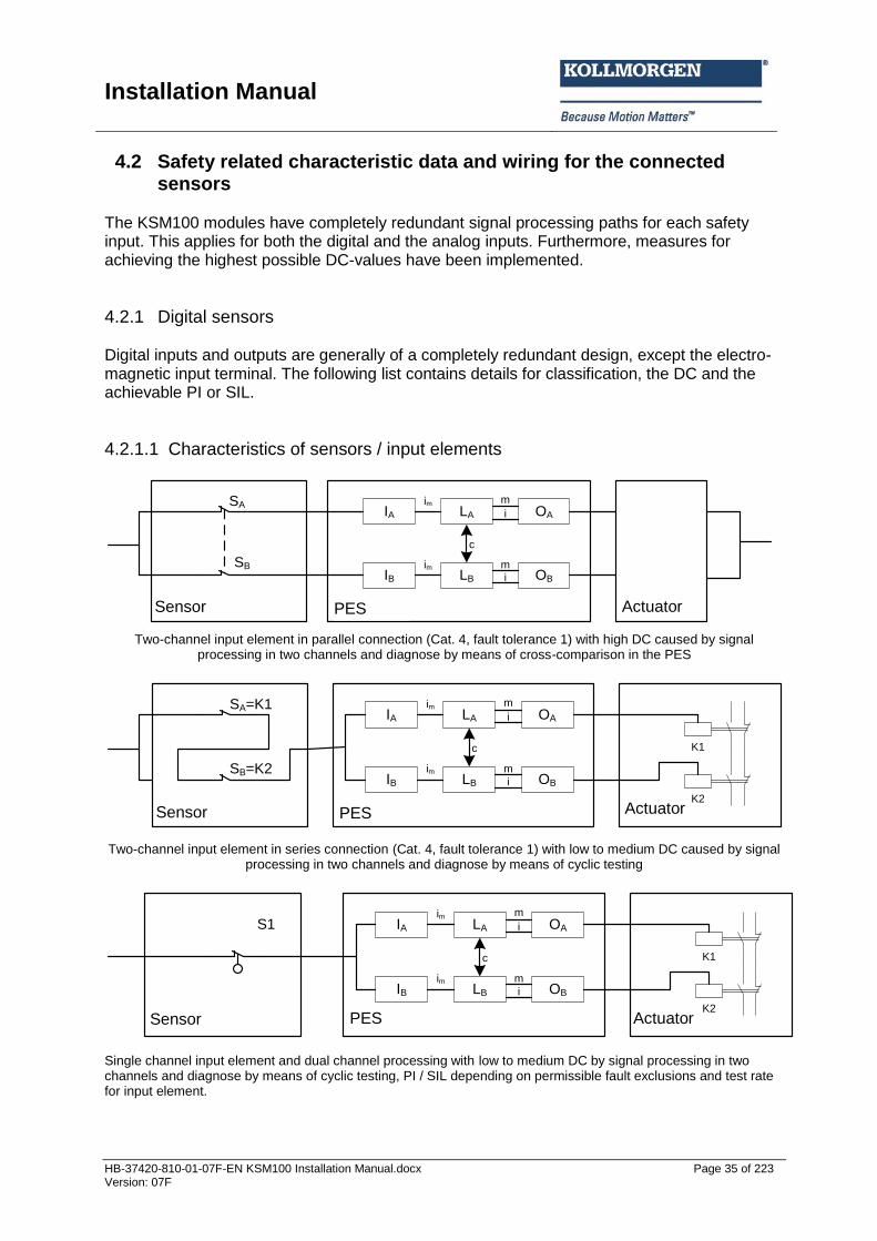
4.2 Safety related characteristic data and wiring for the connected sensors
The KSM100 modules have completely redundant signal processing paths for each safety input. This applies for both the digital and the analog inputs. Furthermore, measures for achieving the highest possible DC-values have been implemented.
4.2.1 Digital sensors Digital inputs and outputs are generally of a completely redundant design, except the electro-magnetic input terminal. The following list contains details for classification, the DC and the achievable PI or SIL.
4.2.1.1 Characteristics of sensors / input elements
IA OALA
IB OBLB
m
m
i
i
c
im
im
Sensor PES Aktuator
SA
SB
Two-channel input element in parallel connection (Cat. 4, fault tolerance 1) with high DC caused by signal
processing in two channels and diagnose by means of cross-comparison in the PES
IA OALA
IB OBLB
m
m
i
i
c
im
im
Sensor PES Aktuator
SA=K1
K1
K2
SB=K2
Two-channel input element in series connection (Cat. 4, fault tolerance 1) with low to medium DC caused by signal processing in two channels and diagnose by means of cyclic testing
IA OALA
IB OBLB
m
m
i
i
c
im
im
Sensor PES Aktuator
K1
K2
S1
Single channel input element and dual channel processing with low to medium DC by signal processing in two channels and diagnose by means of cyclic testing, PI / SIL depending on permissible fault exclusions and test rate for input element.
Sensor Actuator PES
Sensor Actuator PES
Sensor Actuator PES

Installation Manual
HB-37420-810-01-07F-EN KSM100 Installation Manual.docx Page 36 of 223 Version: 07F
4.2.1.2 DC digital sensors/inputs The KSM100 modules ensure far reaching diagnostics functions for the partial input system. These are carried out permanently, or optionally (cross-shorting monitoring by means of pulse identifier, cross-comparison, 2- or multi-channel sensor with/without time-out, start-up test). Permanently active diagnostics functions: Cross-comparison: KSM module inputs are in general internally designed with two channels. The status of input signals is permanently compared crosswise. Only with High signals in both partial input systems the input is considered a High input, should the signal level deviate between both channels, the input is set to Low state. Dynamic test of the partial input system switching threshold: The switching thresholds for detecting the High level are tested cyclically with a high cycle rate. Falling below the defined threshold value a module triggers a module alarm. Dynamic test of the input system's switchability: The switchability of the input system to Low level is tested for all inputs with a high rate, except DI5 -- DI8. Falling below the defined threshold value a module triggers a module alarm. Diagnostics functions to be activated by parameterization: Cross-shorting test: The KSM modules have pulse signal outputs, identified by an unambiguous signature. When performing the cross-shorting test the switching elements of the digital sensors / input elements are supplied with auxiliary voltage by the KSM-module via the pulse signal outputs. The signature is thus stamped on the High signal level of the sensors / input elements and checked by the KSM module. With the signature test short-circuits and cross-shorting to High signals can be recognized. With alternating use of the pulse signals of multi-contacts, parallel signal lines or adjacent terminal assignment, cross-shorting between the respective input elements is detected. Sensors / input elements with 2- or multi-pole contacts without time-out. Several contacts can be assigned to the sensors / input elements. These are therefore compatible with at least 2-channel elements. A High level of the sensor/input element requires a logic series connection of both contacts. Example 1: Input element with 2 normally closed contacts: High level when both contacts are closed. Example 2: Input element with 1 normally closed and 1 normally open contact: High level when normally open contact is actuated and normally closed contact is not actuated.
Installation Manual
HB-37420-810-01-07F-EN KSM100 Installation Manual.docx Page 37 of 223 Version: 07F
Sensors / input elements with 2- or multi-pole contacts with time-out. Same test as before, but additional monitoring of the input signals for compliance with the defined level connections within a time window of 0.5 seconds. Defining the levels over a time period of > 0.5 seconds triggers a module alarm. Start test: Each time the safety module (=KSM module) is switched on, the input element must be tested in direction of the Low signal status (defined Safe State), e.g. by actuating the Emergency Stop button or a door lock after the system has been started. Operational / organizational tests: Apart from the previously mentioned diagnostic measures for the KSM modules, cyclic testing can be performed within the application. These tests can also be used when assessing the DC.
Installation Manual
HB-37420-810-01-07F-EN KSM100 Installation Manual.docx Page 38 of 223 Version: 07F
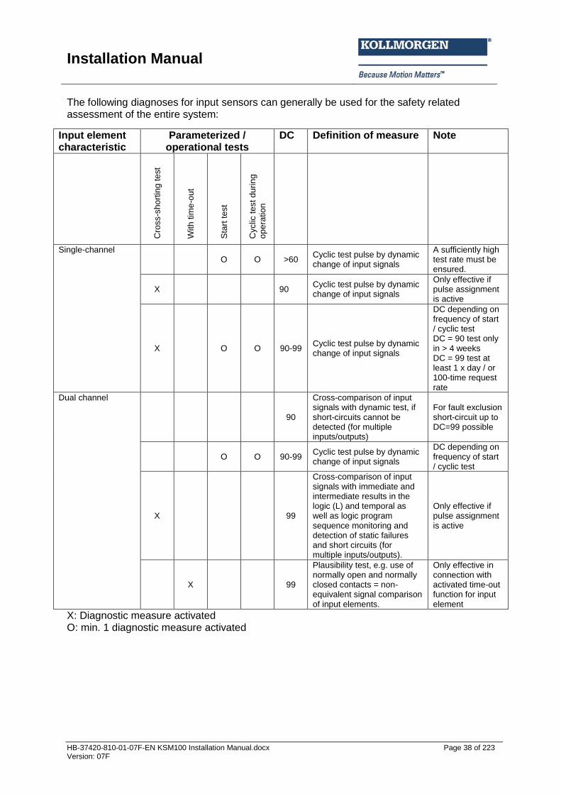
The following diagnoses for input sensors can generally be used for the safety related assessment of the entire system:
Input element characteristic
Parameterized / operational tests
DC Definition of measure Note
C
ross-s
ho
rtin
g te
st
With
tim
e-o
ut
Sta
rt t
est
Cyclic
te
st d
urin
g
op
era
tio
n
Single-channel O O >60
Cyclic test pulse by dynamic change of input signals
A sufficiently high test rate must be ensured.
X 90 Cyclic test pulse by dynamic change of input signals
Only effective if pulse assignment is active
X O O 90-99 Cyclic test pulse by dynamic change of input signals
DC depending on frequency of start / cyclic test DC = 90 test only in > 4 weeks DC = 99 test at least 1 x day / or 100-time request rate
Dual channel
90
Cross-comparison of input signals with dynamic test, if short-circuits cannot be detected (for multiple inputs/outputs)
For fault exclusion short-circuit up to DC=99 possible
O O 90-99 Cyclic test pulse by dynamic change of input signals
DC depending on frequency of start / cyclic test
X 99
Cross-comparison of input signals with immediate and intermediate results in the logic (L) and temporal as well as logic program sequence monitoring and detection of static failures and short circuits (for multiple inputs/outputs).
Only effective if pulse assignment is active
X 99
Plausibility test, e.g. use of normally open and normally closed contacts = non-equivalent signal comparison of input elements.
Only effective in connection with activated time-out function for input element
X: Diagnostic measure activated O: min. 1 diagnostic measure activated
Installation Manual
HB-37420-810-01-07F-EN KSM100 Installation Manual.docx Page 39 of 223 Version: 07F
Safety note:
The manufacturer's data (MTTFD, FIT-numbers, etc.) must be used for a safety related assessment of the partial system “Sensors”.
The DC-values listed in the table must be used conservatively and compliance with the boundary conditions (see table under “Remarks”) must be ensured.
According to the applicable standards, fault exclusions are permitted. The boundary conditions mentioned in this context must permanently be met.
If several sensor systems are required for the correct function of a single safety function, their partial values must be correctly merged by following the chosen method.
Installation Manual
HB-37420-810-01-07F-EN KSM100 Installation Manual.docx Page 40 of 223 Version: 07F
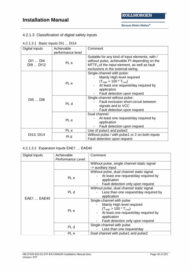
4.2.1.3 Classification of digital safety inputs 4.2.1.3.1 Basic inputs DI1 ... DI14
4.2.1.3.2 Expansion inputs EAE1 … EAE40
Digital inputs Achievable performance level
Comment
DI1 … DI4 DI9 … DI12
PL e
Suitable for any kind of input elements, with / without pulse, achievable PI depending on the MTTFd of the input element, as well as fault exclusions in the external wiring.
DI5 … DI8
PL e
Single-channel with pulse: - Mainly High level required
(THigh > 100 * TLow) - At least one request/day required by
application - Fault detection upon request
PL d
Single-channel without pulse: - Fault exclusion short-circuit between
signals and to VCC - Fault detection upon request
PL e
Dual channel: - At least one request/day required by
application - Fault detection upon request
DI13, DI14 PL e Use of pulse1 and pulse2
Pl d Without pulse / with pulse1 or 2 on both inputs Fault detection upon request
Digital inputs Achievable Performance Level
Comment
EAE1 … EAE40
Without pulse, single channel static signal -> auxiliary input
PL e
Without pulse, dual channel static signal - At least one request/day required by
application - Fault detection only upon request
PL d Without pulse, dual channel static signal
- Less than one request/day required by application
PL e
Single-channel with pulse - Mainly High level required
(THigh > 100 * TLow) - At least one request/day required by
application - Fault detection only upon request
PL d Single-channel with pulse
- Less than one request/day
PL e Dual channel with pulse1 and pulse2
Installation Manual
HB-37420-810-01-07F-EN KSM100 Installation Manual.docx Page 41 of 223 Version: 07F
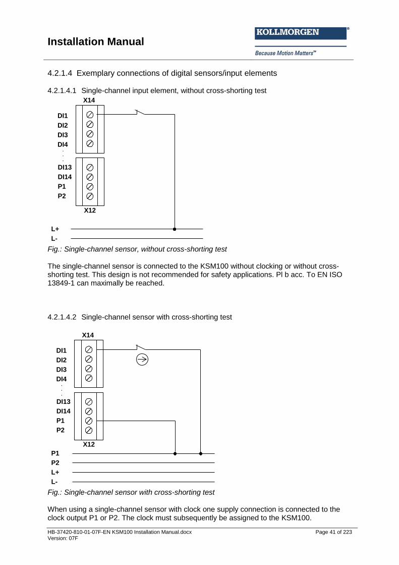
4.2.1.4 Exemplary connections of digital sensors/input elements 4.2.1.4.1 Single-channel input element, without cross-shorting test
DI1
DI2
DI3
DI4
DI13
DI14
P1
P2
L+
L-
X14
X12
.
.
.
Fig.: Single-channel sensor, without cross-shorting test The single-channel sensor is connected to the KSM100 without clocking or without cross-shorting test. This design is not recommended for safety applications. Pl b acc. To EN ISO 13849-1 can maximally be reached. 4.2.1.4.2 Single-channel sensor with cross-shorting test
L+
L-
P2
P1
DI1
DI2
DI3
DI4
DI13
DI14
P1
P2
X14
X12
.
.
.
Fig.: Single-channel sensor with cross-shorting test When using a single-channel sensor with clock one supply connection is connected to the clock output P1 or P2. The clock must subsequently be assigned to the KSM100.
Installation Manual
HB-37420-810-01-07F-EN KSM100 Installation Manual.docx Page 42 of 223 Version: 07F
The use of a single-channel sensor with clock detects: short-circuit to supply voltage DC 24 V short-circuit to DC 0 V cable interruption (current interruption is secure state!) ) However, be cautious in case of a cable short between the two sensor connections, because this is not detected! A short-circuit between P1 and DI1 is also not detected. Due to the single-channel character of the switching element / sensor its failure requires an fault exclusion. This is permissible when using positively disconnecting switches with correct constrained actuation. A series connection of 2 switching elements with corresponding fault exclusion of a double fault is on equal footing with the application. These may be e.g. the safety outputs of an electronic monitoring device (light curtain, switching mat) with internal dual-channel switch-off. PI d acc. to EN ISO 13849-1 can be achieved by using a suitable switching element and with cautious wiring of the sensor. In special cases, i.e. in connection with suitable switching elements and permissible fault exclusions one may also achieve PL e as per EN ISO 13849-1.
Safety note:
Pl e or higher acc. to EN ISO 13849-1 is achieved if the short-circuit between input and associated pulse output as well as the short-circuit between the sensor connections can be excluded. Here one must take care that in a fault scenario the switch must be positively opening in accordance with EN 60947-5-1.. The sensor must additionally be triggered in regular intervals and the safety function requested. Fault exclusions can be achieved in accordance with EN ISO 13849-2, table D8. In case of single-channel use of the inputs, the achievable safety level must be limited to SIL 2 or PL d, if the safety function is demanded at regular intervals.
A series connection of 2 switching elements with fault exclusion for double fault requires testing of the suitability in accordance with the intended safety level of this element. We would like to draw your attention to the applicable regulations in the EC machine directive 2006/42/EC.
For single-channel sensors a safety related use of the inputs is only intended in connection with the pulse outputs.
Installation Manual
HB-37420-810-01-07F-EN KSM100 Installation Manual.docx Page 43 of 223 Version: 07F
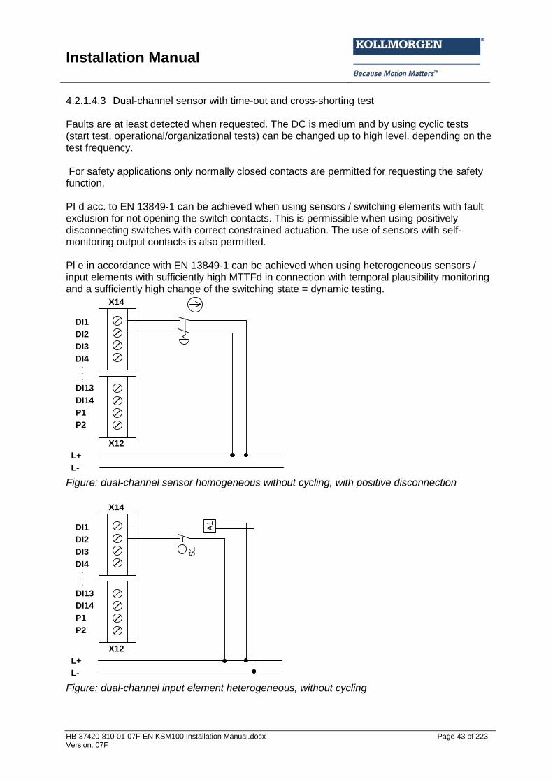
4.2.1.4.3 Dual-channel sensor with time-out and cross-shorting test Faults are at least detected when requested. The DC is medium and by using cyclic tests (start test, operational/organizational tests) can be changed up to high level. depending on the test frequency. For safety applications only normally closed contacts are permitted for requesting the safety function. PI d acc. to EN 13849-1 can be achieved when using sensors / switching elements with fault exclusion for not opening the switch contacts. This is permissible when using positively disconnecting switches with correct constrained actuation. The use of sensors with self-monitoring output contacts is also permitted. Pl e in accordance with EN 13849-1 can be achieved when using heterogeneous sensors / input elements with sufficiently high MTTFd in connection with temporal plausibility monitoring and a sufficiently high change of the switching state = dynamic testing.
DI1
DI2
DI3
DI4
DI13
DI14
P1
P2
X14
.
.
.
L+
L-
X12
Figure: dual-channel sensor homogeneous without cycling, with positive disconnection
DI1
DI2
DI3
DI4
DI13
DI14
P1
P2
X14
.
.
.
L+
L-
X12
S1
A1
Figure: dual-channel input element heterogeneous, without cycling
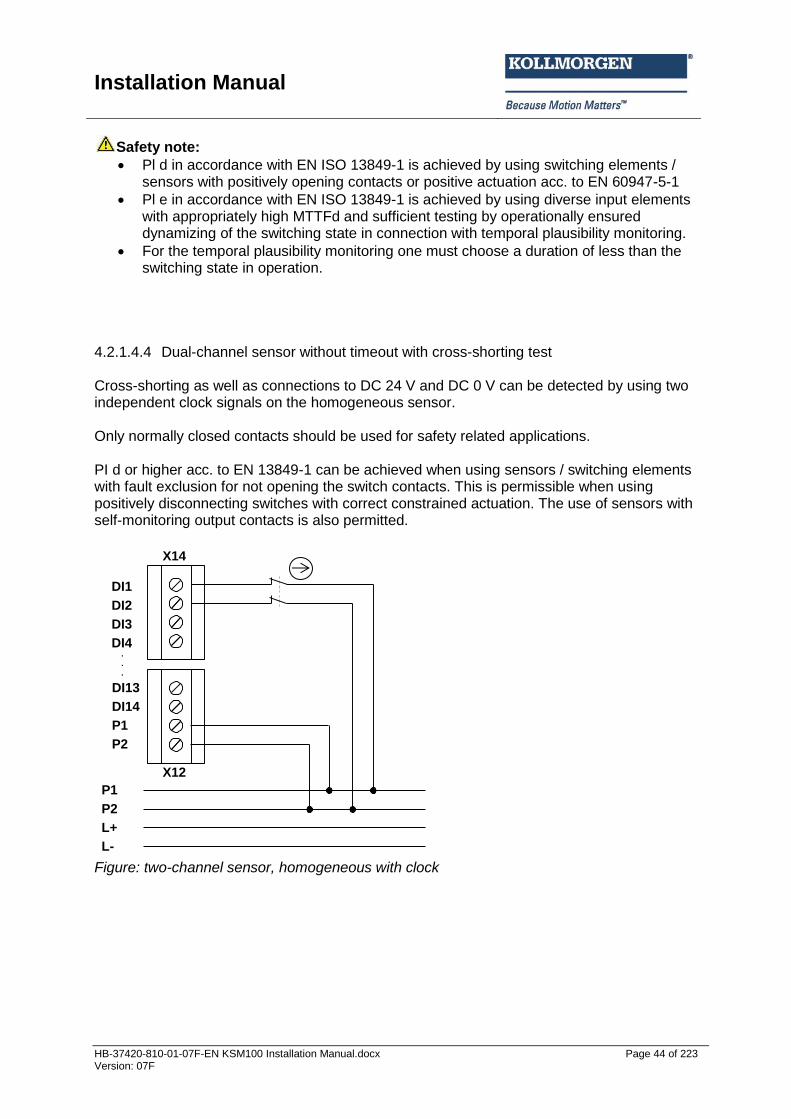
Installation Manual
HB-37420-810-01-07F-EN KSM100 Installation Manual.docx Page 44 of 223 Version: 07F
Safety note:
Pl d in accordance with EN ISO 13849-1 is achieved by using switching elements / sensors with positively opening contacts or positive actuation acc. to EN 60947-5-1
Pl e in accordance with EN ISO 13849-1 is achieved by using diverse input elements with appropriately high MTTFd and sufficient testing by operationally ensured dynamizing of the switching state in connection with temporal plausibility monitoring.
For the temporal plausibility monitoring one must choose a duration of less than the switching state in operation.
4.2.1.4.4 Dual-channel sensor without timeout with cross-shorting test Cross-shorting as well as connections to DC 24 V and DC 0 V can be detected by using two independent clock signals on the homogeneous sensor. Only normally closed contacts should be used for safety related applications. PI d or higher acc. to EN 13849-1 can be achieved when using sensors / switching elements with fault exclusion for not opening the switch contacts. This is permissible when using positively disconnecting switches with correct constrained actuation. The use of sensors with self-monitoring output contacts is also permitted.
DI1
DI2
DI3
DI4
DI13
DI14
P1
P2
X14
.
.
.
L+
L-
P2
P1
X12
Figure: two-channel sensor, homogeneous with clock
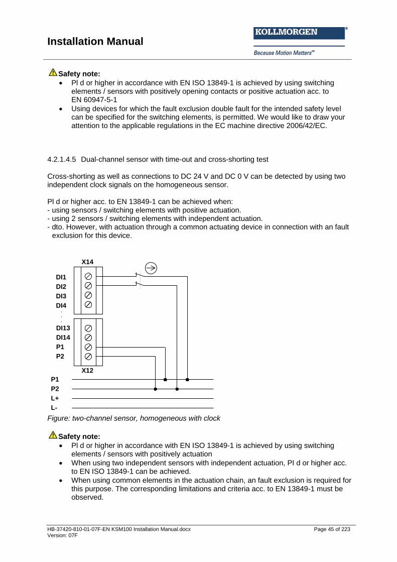
Installation Manual
HB-37420-810-01-07F-EN KSM100 Installation Manual.docx Page 45 of 223 Version: 07F
Safety note:
Pl d or higher in accordance with EN ISO 13849-1 is achieved by using switching elements / sensors with positively opening contacts or positive actuation acc. to EN 60947-5-1
Using devices for which the fault exclusion double fault for the intended safety level can be specified for the switching elements, is permitted. We would like to draw your attention to the applicable regulations in the EC machine directive 2006/42/EC.
4.2.1.4.5 Dual-channel sensor with time-out and cross-shorting test Cross-shorting as well as connections to DC 24 V and DC 0 V can be detected by using two independent clock signals on the homogeneous sensor. Pl d or higher acc. to EN 13849-1 can be achieved when: - using sensors / switching elements with positive actuation. - using 2 sensors / switching elements with independent actuation. - dto. However, with actuation through a common actuating device in connection with an fault
exclusion for this device.
DI1
DI2
DI3
DI4
DI13
DI14
P1
P2
X14
.
.
.
L+
L-
P2
P1
X12
Figure: two-channel sensor, homogeneous with clock
Safety note:
Pl d or higher in accordance with EN ISO 13849-1 is achieved by using switching elements / sensors with positively actuation
When using two independent sensors with independent actuation, PI d or higher acc. to EN ISO 13849-1 can be achieved.
When using common elements in the actuation chain, an fault exclusion is required for this purpose. The corresponding limitations and criteria acc. to EN 13849-1 must be observed.
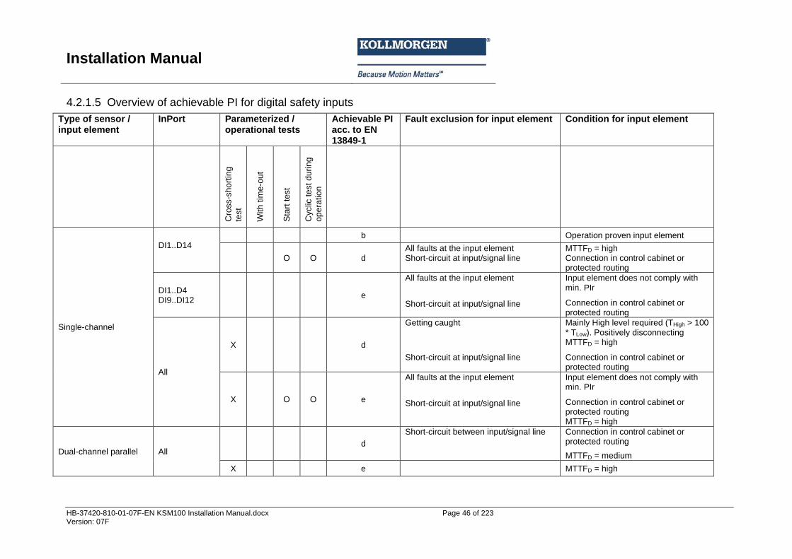
Installation Manual
HB-37420-810-01-07F-EN KSM100 Installation Manual.docx Page 46 of 223 Version: 07F
4.2.1.5 Overview of achievable PI for digital safety inputs
Type of sensor / input element
InPort Parameterized / operational tests
Achievable PI acc. to EN 13849-1
Fault exclusion for input element Condition for input element
Cro
ss-s
ho
rtin
g
test
With
tim
e-o
ut
Sta
rt t
est
Cyclic
te
st d
urin
g
op
era
tio
n
Single-channel
DI1..D14
b Operation proven input element
O O d All faults at the input element Short-circuit at input/signal line
MTTFD = high Connection in control cabinet or protected routing
DI1..D4 DI9..DI12
e
All faults at the input element
Short-circuit at input/signal line
Input element does not comply with min. PIr
Connection in control cabinet or protected routing
All
X d
Getting caught
Short-circuit at input/signal line
Mainly High level required (THigh > 100 * TLow). Positively disconnecting MTTFD = high
Connection in control cabinet or protected routing
X O O e
All faults at the input element
Short-circuit at input/signal line
Input element does not comply with min. PIr
Connection in control cabinet or protected routing MTTFD = high
Dual-channel parallel All
d
Short-circuit between input/signal line
Connection in control cabinet or protected routing
MTTFD = medium
X e MTTFD = high
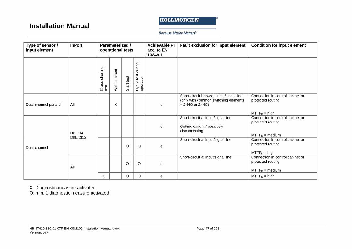
Installation Manual
HB-37420-810-01-07F-EN KSM100 Installation Manual.docx Page 47 of 223 Version: 07F
Type of sensor / input element
InPort Parameterized / operational tests
Achievable PI acc. to EN 13849-1
Fault exclusion for input element Condition for input element
Cro
ss-s
ho
rtin
g
test
With
tim
e-o
ut
Sta
rt t
est
Cyclic
te
st d
urin
g
op
era
tio
n
Dual-channel parallel All X
e
Short-circuit between input/signal line (only with common switching elements = 2xNO or 2xNC)
Connection in control cabinet or protected routing MTTFD = high
Dual-channel
DI1..D4 DI9..DI12
d
Short-circuit at input/signal line Getting caught / positively disconnecting
Connection in control cabinet or protected routing MTTFD = medium
O O e
Short-circuit at input/signal line
Connection in control cabinet or protected routing MTTFD = high
All O O d
Short-circuit at input/signal line
Connection in control cabinet or protected routing MTTFD = medium
X O O e MTTFD = high
X: Diagnostic measure activated O: min. 1 diagnostic measure activated
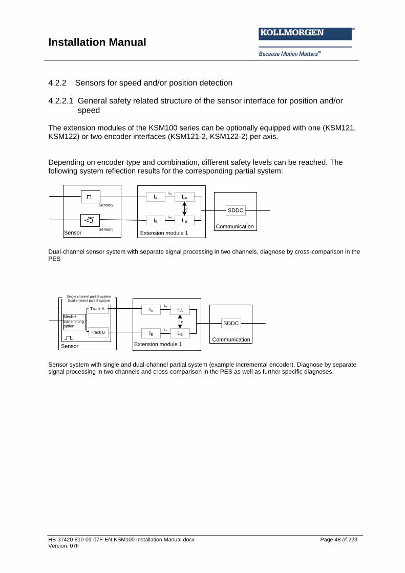
Installation Manual
HB-37420-810-01-07F-EN KSM100 Installation Manual.docx Page 48 of 223 Version: 07F
4.2.2 Sensors for speed and/or position detection
4.2.2.1 General safety related structure of the sensor interface for position and/or speed
The extension modules of the KSM100 series can be optionally equipped with one (KSM121, KSM122) or two encoder interfaces (KSM121-2, KSM122-2) per axis. Depending on encoder type and combination, different safety levels can be reached. The following system reflection results for the corresponding partial system:
Sensor
SensorA
SensorB
IA LA
IB LB
c
im
im
Erweiterungsbaugruppe 1
SDDC
Kommunikation
Dual-channel sensor system with separate signal processing in two channels, diagnose by cross-comparison in the PES
IA LA
IB LB
c
im
im
Erweiterungsbaugruppe 1
SDDC
KommunikationSensor
Eink. Teilsyst.
Mech.+
Sendeopt.
Spur A
Spur B
Zweik. Teilsyst.
Sensor system with single and dual-channel partial system (example incremental encoder). Diagnose by separate signal processing in two channels and cross-comparison in the PES as well as further specific diagnoses.
Sensor Communication
Extension module 1
Single channel partial system Dual-channel partial system
Mech.+ transmitting option
Sensor
Communication
Extension module 1
Track A
Track B

Installation Manual
HB-37420-810-01-07F-EN KSM100 Installation Manual.docx Page 49 of 223 Version: 07F
4.2.2.2 General diagnostic measures for encoder interface For fault detection in the sensor system the KSM series has a number of diagnostic measures implemented, depending on the chosen encoder type or its combination. These are automatically activated when choosing the encoder type. With respect to their type and effectiveness diagnostic measures can generally be classified using the following table: Diagnoses for sensors for position and/or speed detection:
Measure DC Note Use
Cross-comparison of input signals with immediate and intermediate results in the logic (L) and temporal as well as logic program sequence monitoring and detection of static failures and short circuits (for multiple inputs/outputs).
99 Only to be used for: - dual-channel sensor
systems (2 separate sensors),
- the dual channel partial system of single channel sensors (incremental encoder)
- Diagnose for the single and dual channel partial system of specially suitable sensor systems (SIN/COS-encoder, resolver)
- Dynamic operation / no standstill monitoring
Monitoring of 2-channel sensor systems or the corresponding partial system of sensors for dynamic operation Not to be used for standstill monitoring!
Cross-comparison of input signals without dynamic test
80-95%
DC depends on the frequency of the dynamic condition, i.e. standstill or movement, as well as on the quality of the monitoring measure (80 - 90% for incremental encoder, 95 % for SIN/COS-encoder)
Monitoring of 2-channel sensor systems or the corresponding partial system of sensors for non-dynamic operation To be used especially for standstill monitoring!
Monitoring of some features of the sensor (response time, the area of analog signals, e.g. electric resistance, capacity)
60 Diagnose of specific features of sensors, only to be used for speed and position sensors as per chapter 4.3.
Monitoring of the single-channel partial system in single-channel sensor systems
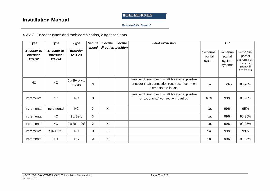
Installation Manual
HB-37420-810-01-07F-EN KSM100 Installation Manual.docx Page 50 of 223 Version: 07F
4.2.2.3 Encoder types and their combination, diagnostic data
Type
Encoder to
interface
X31/32
Type
Encoder to
interface
X33/34
Type
Encoder
to X 23
Secure
speed
Secure
direction
Secure
position
Fault exclusion DC
1-channel
partial
system
2-channel
partial
system
dynamic
2-channel partial
system non-dynamic (standstill
monitoring)
NC NC 1 x Bero + 1
x Bero X
Fault exclusion mech. shaft breakage, positive
encoder shaft connection required, if common
elements are in use. n.a. 99% 80-90%
Incremental NC NC X
Fault exclusion mech. shaft breakage, positive
encoder shaft connection required 60% 99% 80-90%
Incremental Incremental NC X X
n.a. 99% 95%
Incremental NC 1 x Bero X
n.a. 99% 90-95%
Incremental NC 2 x Bero 90° X X
n.a. 99% 90-95%
Incremental SIN/COS NC X X
n.a. 99% 99%
Incremental HTL NC X X
n.a. 99% 90-95%
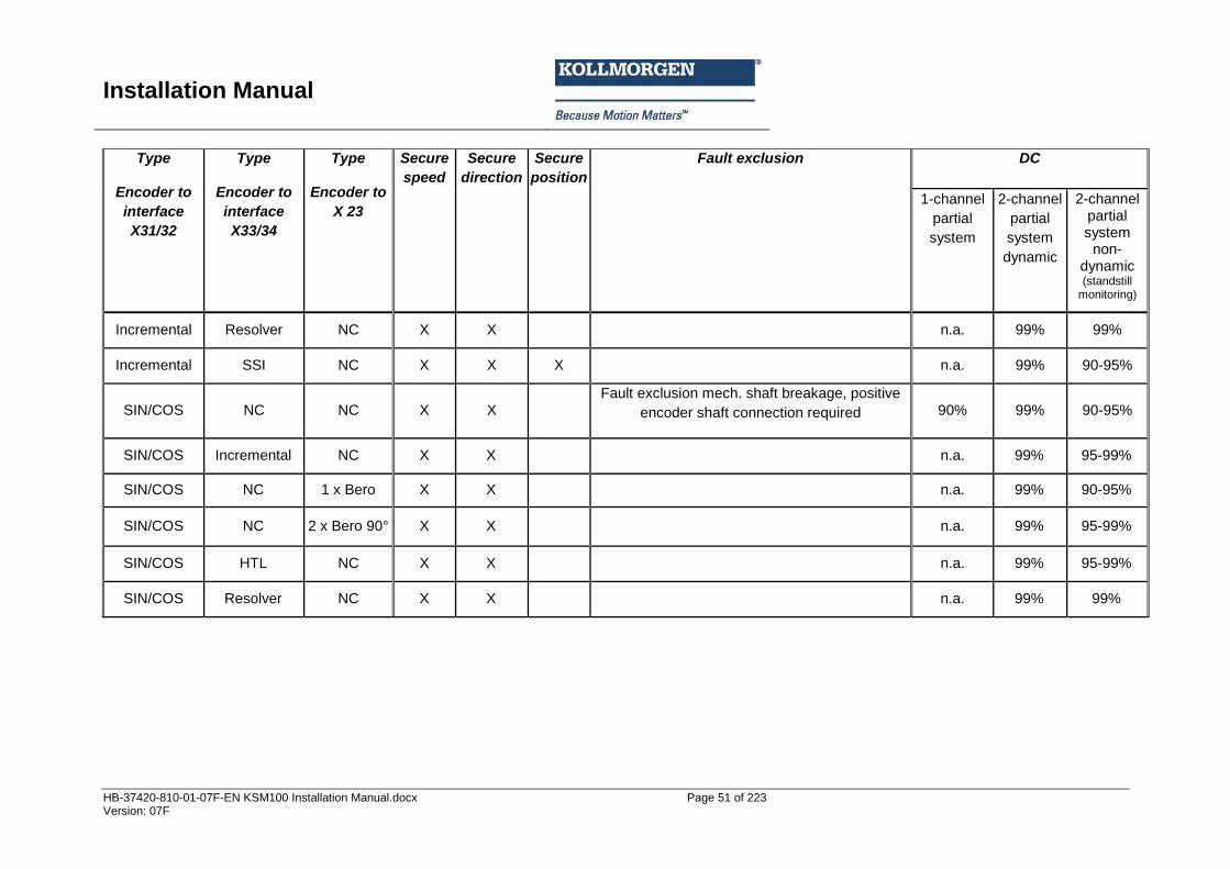
Installation Manual
HB-37420-810-01-07F-EN KSM100 Installation Manual.docx Page 51 of 223 Version: 07F
Type
Encoder to
interface
X31/32
Type
Encoder to
interface
X33/34
Type
Encoder to
X 23
Secure
speed
Secure
direction
Secure
position
Fault exclusion DC
1-channel
partial
system
2-channel
partial
system
dynamic
2-channel partial system
non-dynamic (standstill
monitoring)
Incremental Resolver NC X X
n.a. 99% 99%
Incremental SSI NC X X X
n.a. 99% 90-95%
SIN/COS NC NC X X
Fault exclusion mech. shaft breakage, positive
encoder shaft connection required 90% 99% 90-95%
SIN/COS Incremental NC X X
n.a. 99% 95-99%
SIN/COS NC 1 x Bero X X
n.a. 99% 90-95%
SIN/COS NC 2 x Bero 90° X X
n.a. 99% 95-99%
SIN/COS HTL NC X X
n.a. 99% 95-99%
SIN/COS Resolver NC X X
n.a. 99% 99%
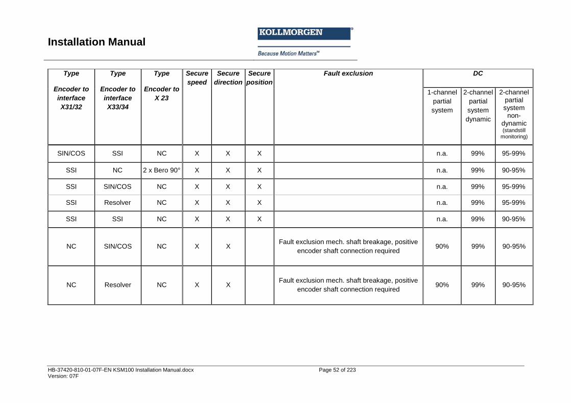
Installation Manual
HB-37420-810-01-07F-EN KSM100 Installation Manual.docx Page 52 of 223 Version: 07F
Type
Encoder to
interface
X31/32
Type
Encoder to
interface
X33/34
Type
Encoder to
X 23
Secure
speed
Secure
direction
Secure
position
Fault exclusion DC
1-channel
partial
system
2-channel
partial
system
dynamic
2-channel partial system
non-dynamic (standstill
monitoring)
SIN/COS SSI NC X X X
n.a. 99% 95-99%
SSI NC 2 x Bero 90° X X X
n.a. 99% 90-95%
SSI SIN/COS NC X X X
n.a. 99% 95-99%
SSI Resolver NC X X X
n.a. 99% 95-99%
SSI SSI NC X X X
n.a. 99% 90-95%
NC SIN/COS NC X X
Fault exclusion mech. shaft breakage, positive
encoder shaft connection required 90% 99% 90-95%
NC Resolver NC X X
Fault exclusion mech. shaft breakage, positive
encoder shaft connection required 90% 99% 90-95%
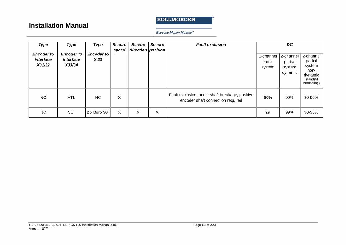
Installation Manual
HB-37420-810-01-07F-EN KSM100 Installation Manual.docx Page 53 of 223 Version: 07F
Type
Encoder to
interface
X31/32
Type
Encoder to
interface
X33/34
Type
Encoder to
X 23
Secure
speed
Secure
direction
Secure
position
Fault exclusion DC
1-channel
partial
system
2-channel
partial
system
dynamic
2-channel partial system
non-dynamic (standstill
monitoring)
NC HTL NC X
Fault exclusion mech. shaft breakage, positive
encoder shaft connection required 60% 99% 80-90%
NC SSI 2 x Bero 90° X X X
n.a. 99% 90-95%
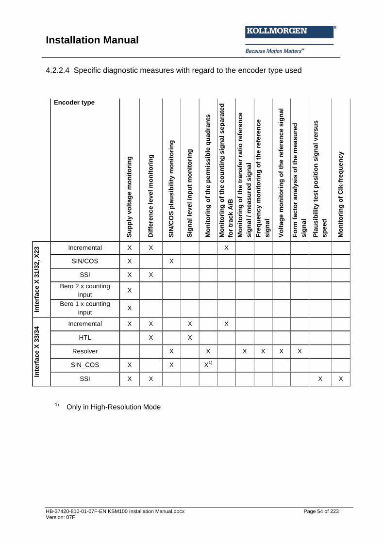
Installation Manual
HB-37420-810-01-07F-EN KSM100 Installation Manual.docx Page 54 of 223 Version: 07F
4.2.2.4 Specific diagnostic measures with regard to the encoder type used
Encoder type
Su
pp
ly v
olt
ag
e m
on
ito
rin
g
Dif
fere
nc
e le
vel m
on
ito
rin
g
SIN
/CO
S p
lau
sib
ilit
y m
on
ito
rin
g
Sig
nal le
ve
l in
pu
t m
on
ito
rin
g
Mo
nit
ori
ng
of
the p
erm
iss
ible
qu
ad
ran
ts
Mo
nit
ori
ng
of
the c
ou
nti
ng
sig
nal s
ep
ara
ted
for
track
A/B
Mo
nit
ori
ng
of
the t
ran
sfe
r ra
tio
refe
ren
ce
sig
nal / m
easu
red
sig
nal
Fre
qu
en
cy
mo
nit
ori
ng
of
the r
efe
ren
ce
sig
nal
Vo
ltag
e m
on
ito
rin
g o
f th
e r
efe
ren
ce
sig
nal
Fo
rm f
acto
r an
aly
sis
of
the m
ea
su
red
sig
nal
Pla
us
ibilit
y t
est
po
sit
ion
sig
nal v
ers
us
sp
eed
Mo
nit
ori
ng
of
Clk
-fre
qu
en
cy
Inte
rface
X 3
1/3
2,
X23
Incremental X X X
SIN/COS X X
SSI X X
Bero 2 x counting
input X
Bero 1 x counting
input X
Inte
rface
X 3
3/3
4 Incremental X X X X
HTL
X X
Resolver X X X X X X
SIN_COS X X X1)
SSI X X X X
1) Only in High-Resolution Mode
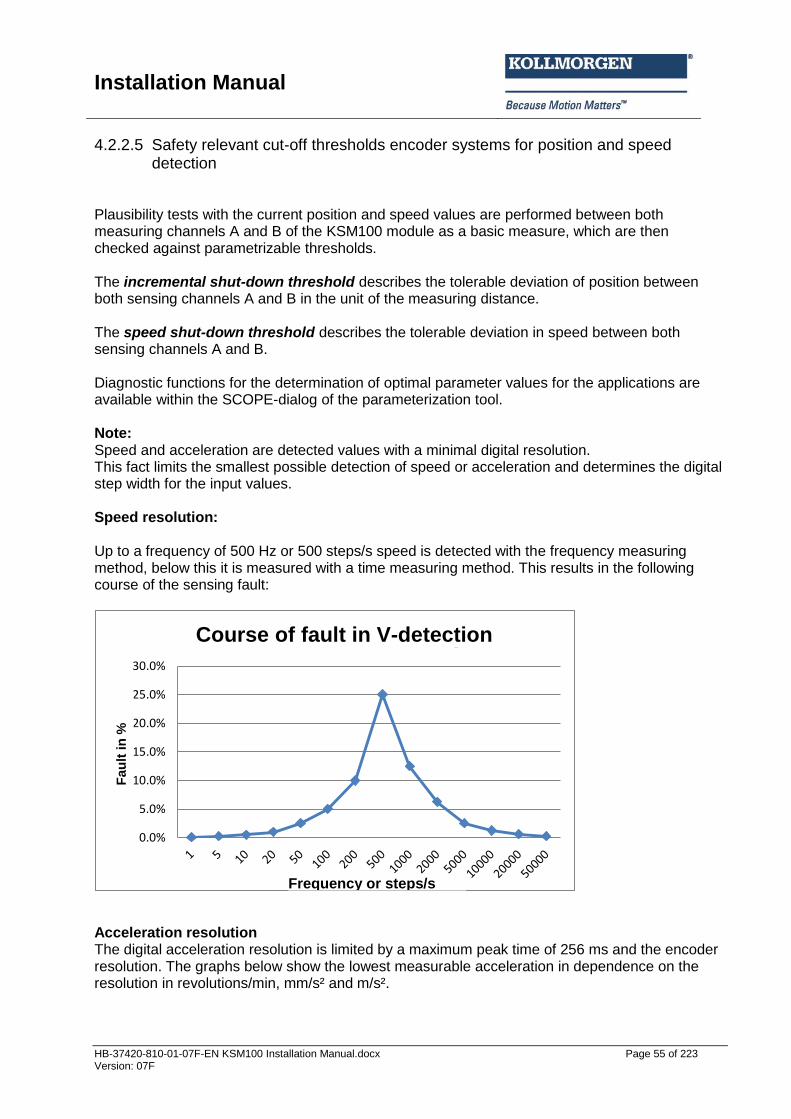
Installation Manual
HB-37420-810-01-07F-EN KSM100 Installation Manual.docx Page 55 of 223 Version: 07F
4.2.2.5 Safety relevant cut-off thresholds encoder systems for position and speed detection
Plausibility tests with the current position and speed values are performed between both measuring channels A and B of the KSM100 module as a basic measure, which are then checked against parametrizable thresholds. The incremental shut-down threshold describes the tolerable deviation of position between both sensing channels A and B in the unit of the measuring distance. The speed shut-down threshold describes the tolerable deviation in speed between both sensing channels A and B. Diagnostic functions for the determination of optimal parameter values for the applications are available within the SCOPE-dialog of the parameterization tool. Note: Speed and acceleration are detected values with a minimal digital resolution. This fact limits the smallest possible detection of speed or acceleration and determines the digital step width for the input values. Speed resolution: Up to a frequency of 500 Hz or 500 steps/s speed is detected with the frequency measuring method, below this it is measured with a time measuring method. This results in the following course of the sensing fault:
Acceleration resolution The digital acceleration resolution is limited by a maximum peak time of 256 ms and the encoder resolution. The graphs below show the lowest measurable acceleration in dependence on the resolution in revolutions/min, mm/s² and m/s².
0.0%
5.0%
10.0%
15.0%
20.0%
25.0%
30.0%
Feh
ler
in %
Fehlerverlauf V-Erfassung
Frequenz, bzw. Schritte/s
Course of fault in V-detection
Frequency or steps/s
Fau
lt in
%
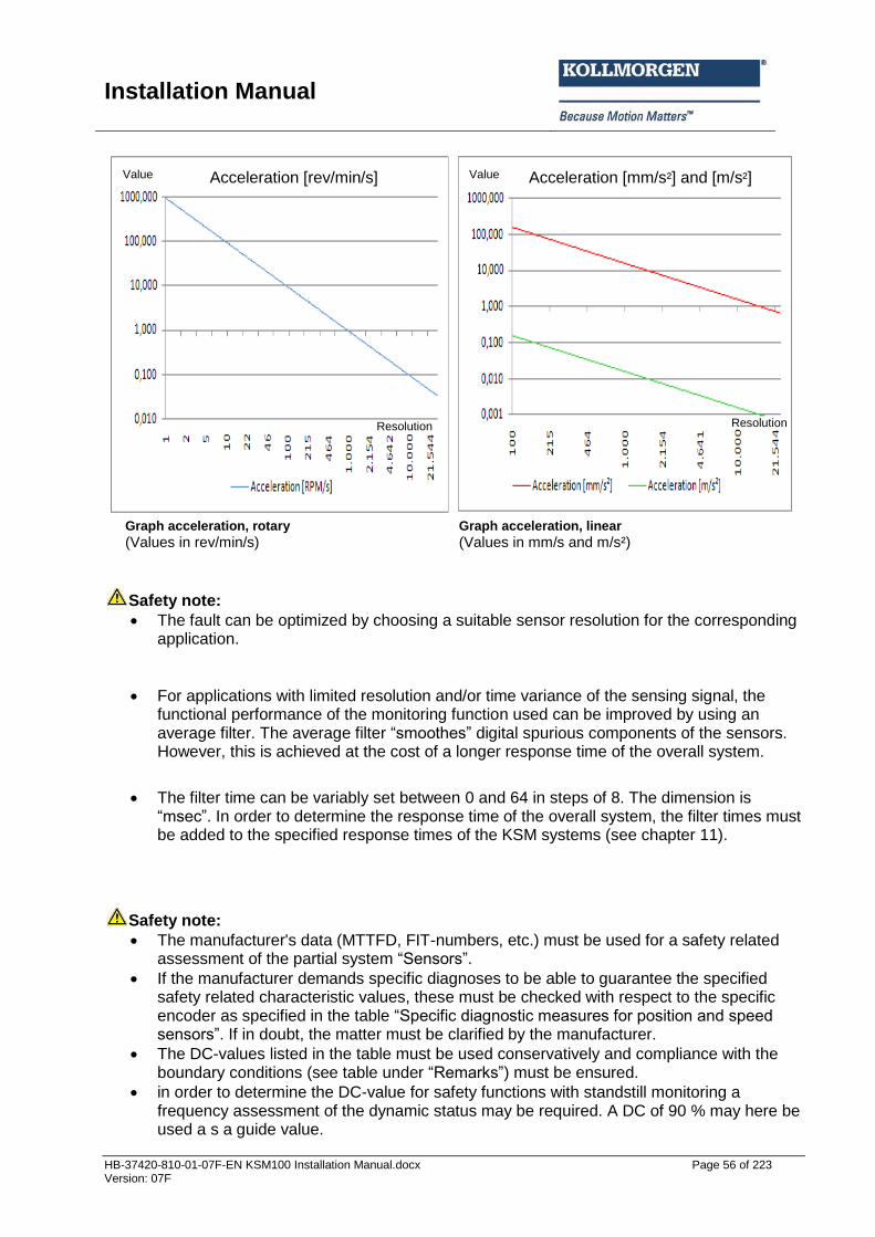
Installation Manual
HB-37420-810-01-07F-EN KSM100 Installation Manual.docx Page 56 of 223 Version: 07F
Graph acceleration, rotary Graph acceleration, linear
(Values in rev/min/s) (Values in mm/s and m/s²)
Safety note:
The fault can be optimized by choosing a suitable sensor resolution for the corresponding application.
For applications with limited resolution and/or time variance of the sensing signal, the functional performance of the monitoring function used can be improved by using an average filter. The average filter “smoothes” digital spurious components of the sensors. However, this is achieved at the cost of a longer response time of the overall system.
The filter time can be variably set between 0 and 64 in steps of 8. The dimension is “msec”. In order to determine the response time of the overall system, the filter times must be added to the specified response times of the KSM systems (see chapter 11).
Safety note:
The manufacturer's data (MTTFD, FIT-numbers, etc.) must be used for a safety related assessment of the partial system “Sensors”.
If the manufacturer demands specific diagnoses to be able to guarantee the specified safety related characteristic values, these must be checked with respect to the specific encoder as specified in the table “Specific diagnostic measures for position and speed sensors”. If in doubt, the matter must be clarified by the manufacturer.
The DC-values listed in the table must be used conservatively and compliance with the boundary conditions (see table under “Remarks”) must be ensured.
in order to determine the DC-value for safety functions with standstill monitoring a frequency assessment of the dynamic status may be required. A DC of 90 % may here be used a s a guide value.
Resolution Resolution
Value Value Acceleration [rev/min/s] Acceleration [mm/s²] and [m/s²]

Installation Manual
HB-37420-810-01-07F-EN KSM100 Installation Manual.docx Page 57 of 223 Version: 07F
According to the applicable standards, fault exclusions are permitted. The boundary conditions mentioned in this context must permanently be met.
If several sensor systems are required for the correct function of a single safety function, their partial values must be correctly merged by following the chosen method. This applies also for a combination of digital and analog sensors (e.g. securely reduced speed with open safety door = door contact + encoder for speed detection)
By choosing a suitable resolution of the sensor system a sufficiently low tolerance with regard to the corresponding cut-off thresholds for the individual safety functions must be ensured.
When using the encoder input filter one must consider the extension of the response time when assessing the safety related function.

Installation Manual
HB-37420-810-01-07F-EN KSM100 Installation Manual.docx Page 58 of 223 Version: 07F
4.2.2.6 Safety related assessment of encoder types or there combination Due to the monitoring functions implemented in the KSM-series, no special demands are initially made on the internal design of the encoder electronics in applications with encoder systems, i.e. standard encoders can normally be used. A safety related assessment of the overall arrangement must generally be made. Data issued by the encoder manufacturer (FIT, MTTF) as well as the DC from the table in 4.2.2 must in this case be used. When using individual encoders at least an fault exclusion for the mechanical actuating chain, as well as for the single-channel part of must be made under due consideration of the applicable specification in EN 13849-1. Furthermore, the information in 4.2.2 must also be observed. PI d and higher acc. to EN 13849-1 is normally reached by a combination of two encoders with prioritized different technology and separated mechanical linking. The use of compact encoders with internal 2-channel structure of different technology is also suitable for applications up to PI e acc. to EN 13849-1, however, under due consideration of the specifically required fault exclusions and their permissibility. Normally one should use encoders with proven safety related characteristics, the safety level of which meets the demanded level.
Safety note:
The use of standard encoders or a combination of standard encoders is permitted. For the overall arrangement consisting of encoder, further sensors/switching elements for triggering the safety function, the KSM-module and their cut-off channel a safety related assessment is strictly required. For determining the achieved safety level one needs, among others, information from the manufacturer (FIT, MTTF) and the DC as specified under 4.2.2.
If only one encoder is used, the fault exclusion “shaft breakage / fault in the mechanical encoder connection” is required. Suitable measures must be applied for this purpose, e.g. a positive connection of the encoder by means of slot shim or locking pin. The applicable information issued by the manufacturer as well as EN 138549-1 with respect to requirements and permissibility of the fault exclusion must strictly be followed.
Encoders with proven safety related characteristics must preferably be used as individual encoders. The safety level of these encoders must at least meet the intended safety level of the overall arrangement. The information of the manufacturer with respect to diagnostic measures, mechanical connection and measures for the voltage supply must be strictly followed.
SIN/COS encoder: The internal structure of the sensor system must be designed in such a way, that output signals for both tracks can be generated independently from each other and Common-Cause faults can be ruled out. Evidence of the mechanical design, e.g. fastening of the code disc on the shaft, must also be provided. Encoders with proven safety related characteristics should preferably be used.
When using compact encoders with internal dual-channel structure, such as e.g. SSI + incremental/SinCos, you must strictly follow the instructions of the manufacturer concerning safety related characteristics, diagnostic measures, mechanical connection and measures concerning the electric power supply. The safety level of the encoder must at least meet the intended safety level of the overall arrangement. Encoders with proven safety related characteristics should preferably be used.

Installation Manual
HB-37420-810-01-07F-EN KSM100 Installation Manual.docx Page 59 of 223 Version: 07F
The KSM100 module generally detects the following faults in the external encoder system:
Short-circuits between safety relevant signal lines
Interruptions in safety relevant signal lines
Stuck at 0 or 1 on one or all safety relevant signal lines Each encoder type has further specific diagnoses for fault detection in the external encoder system assigned. The following list sows the respective diagnostic measures for the individual encoders, together with the limiting parameters.
Safety note:
The diagnostic measures obviously have tolerances because of measuring inaccuracies. These tolerances must be accounted for in the safety related assessment.
The limiting values for the corresponding diagnostic measures are partly parametrizable or fixed. The diagnostic coverages resulting from this must be assessed in relation to the application and included in the safety related overall assessment.
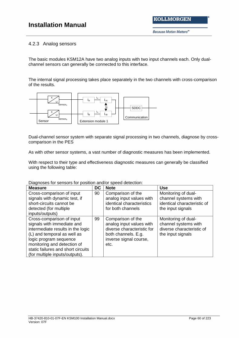
Installation Manual
HB-37420-810-01-07F-EN KSM100 Installation Manual.docx Page 60 of 223 Version: 07F
4.2.3 Analog sensors The basic modules KSM12A have two analog inputs with two input channels each. Only dual-channel sensors can generally be connected to this interface. The internal signal processing takes place separately in the two channels with cross-comparison of the results.
IA LA
IB LB
c
im
im
Erweiterungsbaugruppe 1
SDDC
KommunikationSensor
SensorA
SensorB
X
X
U
U
Dual-channel sensor system with separate signal processing in two channels, diagnose by cross-comparison in the PES As with other sensor systems, a vast number of diagnostic measures has been implemented. With respect to their type and effectiveness diagnostic measures can generally be classified using the following table: Diagnoses for sensors for position and/or speed detection:
Measure DC Note Use
Cross-comparison of input signals with dynamic test, if short-circuits cannot be detected (for multiple inputs/outputs)
90 Comparison of the analog input values with identical characteristics for both channels
Monitoring of dual-channel systems with identical characteristic of the input signals
Cross-comparison of input signals with immediate and intermediate results in the logic (L) and temporal as well as logic program sequence monitoring and detection of static failures and short circuits (for multiple inputs/outputs).
99 Comparison of the analog input values with diverse characteristic for both channels. E.g. inverse signal course, etc.
Monitoring of dual-channel systems with diverse characteristic of the input signals
Sensor Communication
Extension module 1
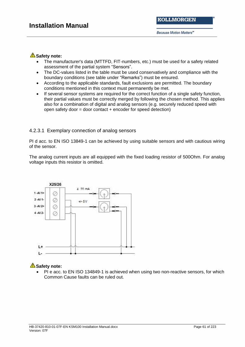
Installation Manual
HB-37420-810-01-07F-EN KSM100 Installation Manual.docx Page 61 of 223 Version: 07F
Safety note:
The manufacturer's data (MTTFD, FIT-numbers, etc.) must be used for a safety related assessment of the partial system “Sensors”.
The DC-values listed in the table must be used conservatively and compliance with the boundary conditions (see table under “Remarks”) must be ensured.
According to the applicable standards, fault exclusions are permitted. The boundary conditions mentioned in this context must permanently be met.
If several sensor systems are required for the correct function of a single safety function, their partial values must be correctly merged by following the chosen method. This applies also for a combination of digital and analog sensors (e.g. securely reduced speed with open safety door = door contact + encoder for speed detection)
4.2.3.1 Exemplary connection of analog sensors PI d acc. to EN ISO 13849-1 can be achieved by using suitable sensors and with cautious wiring of the sensor. The analog current inputs are all equipped with the fixed loading resistor of 500Ohm. For analog voltage inputs this resistor is omitted.
Safety note:
PI e acc. to EN ISO 134849-1 is achieved when using two non-reactive sensors, for which Common Cause faults can be ruled out.
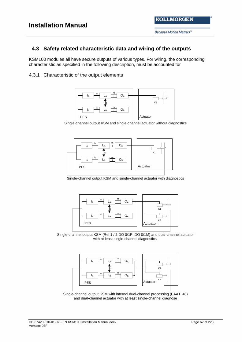
Installation Manual
HB-37420-810-01-07F-EN KSM100 Installation Manual.docx Page 62 of 223 Version: 07F
4.3 Safety related characteristic data and wiring of the outputs KSM100 modules all have secure outputs of various types. For wiring, the corresponding characteristic as specified in the following description, must be accounted for
4.3.1 Characteristic of the output elements
IA OALA
IB OBLB
m
m
i
i
c
im
im
PES Aktuator
K1
Single-channel output KSM and single-channel actuator without diagnostics
IA OALA
IB OBLB
m
m
i
i
c
im
im
PES Aktuator
K1
Single-channel output KSM and single-channel actuator with diagnostics
IA OALA
IB OBLB
m
m
i
i
c
im
im
PES Aktuator
K1
K2
Single-channel output KSM (Rel 1 / 2 DO 0/1P, DO 0/1M) and dual-channel actuator
with at least single-channel diagnostics.
IA OALA
IB OBLB
m
m
i
i
c
im
im
PES Aktuator
K1
K2
Single-channel output KSM with internal dual-channel processing (EAA1..40)
and dual-channel actuator with at least single-channel diagnose
Actuator
Actuator
Actuator
Actuator
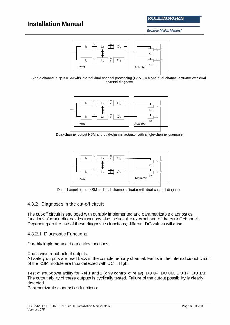
Installation Manual
HB-37420-810-01-07F-EN KSM100 Installation Manual.docx Page 63 of 223 Version: 07F
IA OALA
IB OBLB
m
m
i
i
c
im
im
PES Aktuator
K1
K2
Single-channel output KSM with internal dual-channel processing (EAA1..40) and dual-channel actuator with dual-
channel diagnose
IA OALA
IB OBLB
m
m
i
i
c
im
im
PES Aktuator
K1
K2
Dual-channel output KSM and dual-channel actuator with single-channel diagnose
IA OALA
IB OBLB
m
m
i
i
c
im
im
PES Aktuator
K1
K2
Dual-channel output KSM and dual-channel actuator with dual-channel diagnose
4.3.2 Diagnoses in the cut-off circuit The cut-off circuit is equipped with durably implemented and parametrizable diagnostics functions. Certain diagnostics functions also include the external part of the cut-off channel. Depending on the use of these diagnostics functions, different DC-values will arise.
4.3.2.1 Diagnostic Functions Durably implemented diagnostics functions: Cross-wise readback of outputs: All safety outputs are read back in the complementary channel. Faults in the internal cutout circuit of the KSM module are thus detected with DC = High. Test of shut-down ability for Rel 1 and 2 (only control of relay), DO 0P, DO 0M, DO 1P, DO 1M: The cutout ability of these outputs is cyclically tested. Failure of the cutout possibility is clearly detected. Parametrizable diagnostics functions:
Actuator
Actuator
Actuator

Installation Manual
HB-37420-810-01-07F-EN KSM100 Installation Manual.docx Page 64 of 223 Version: 07F
Readback of the actuator status via auxiliary contacts, position indicators, etc.: The current status of the actuator is detected by correspondingly suitable auxiliary contacts or position indicators and compared with the nominal status. Any deviation is thereby clearly recognized. Note: The DC depends on a single-channel or dual-channel diagnose as well as on the switching frequency. Testing the cutout ability for EAA1..40: Once this function has been activated, the cutout ability of these outputs is cyclically tested. Failure of the cutout possibility is clearly detected.
4.3.2.2 Overview DC with respect to the chosen diagnostics functions Measure DC Note Use
Monitoring of outputs b a channel without dynamic test.
0-90% DC depending on switching frequency When using elements for switching amplification external relays or contactors) only effective in connection with the readback function of the switching contacts
Monitoring of electro-mechanical, pneumatic or hydraulic actuators / outputs
Redundant cutout path with monitoring one of the drive elements
90% When using elements for switching amplification external relays or contactors) only effective in connection with the readback function of the switching contacts
Monitoring of the outputs with direct functions as safety circuit or monitoring of safety circuits with elements for switching amplification of pneumatic / hydraulic control valves in connection with readback functions from their switching status
Cross-comparison of input signals with immediate and intermediate results in the logic (L) and temporal as well as logic program sequence monitoring and detection of static failures and short circuits (for multiple inputs/outputs).
99% When using elements for switching amplification external relays or contactors) only effective in connection with the readback function of the switching contacts For applications with frequent safety shut-down requests these tests should be performed more frequently, e.g. at the beginning of the shift, 1 x per week. However, a test should at least be carried out cyclically 1 x year.
Monitoring of the outputs with direct functions as safety circuit or monitoring of safety circuits with elements for switching amplification of pneumatic / hydraulic control valves in connection with readback functions from their switching status
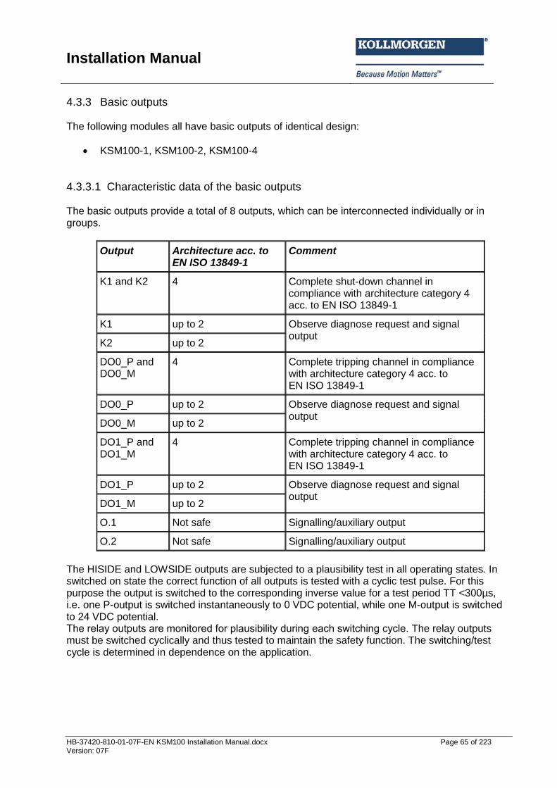
Installation Manual
HB-37420-810-01-07F-EN KSM100 Installation Manual.docx Page 65 of 223 Version: 07F
4.3.3 Basic outputs The following modules all have basic outputs of identical design:
KSM100-1, KSM100-2, KSM100-4
4.3.3.1 Characteristic data of the basic outputs The basic outputs provide a total of 8 outputs, which can be interconnected individually or in groups.
Output Architecture acc. to EN ISO 13849-1
Comment
K1 and K2 4 Complete shut-down channel in compliance with architecture category 4 acc. to EN ISO 13849-1
K1 up to 2 Observe diagnose request and signal output
K2 up to 2
DO0_P and DO0_M
4 Complete tripping channel in compliance with architecture category 4 acc. to EN ISO 13849-1
DO0_P up to 2 Observe diagnose request and signal output
DO0_M up to 2
DO1_P and DO1_M
4 Complete tripping channel in compliance with architecture category 4 acc. to EN ISO 13849-1
DO1_P up to 2 Observe diagnose request and signal output
DO1_M up to 2
O.1 Not safe Signalling/auxiliary output
O.2 Not safe Signalling/auxiliary output
The HISIDE and LOWSIDE outputs are subjected to a plausibility test in all operating states. In switched on state the correct function of all outputs is tested with a cyclic test pulse. For this purpose the output is switched to the corresponding inverse value for a test period TT <300µs, i.e. one P-output is switched instantaneously to 0 VDC potential, while one M-output is switched to 24 VDC potential. The rela outputs are monitored for plausibilit during each s itching c cle. The relay outputs must be switched cyclically and thus tested to maintain the safety function. The switching/test cycle is determined in dependence on the application.
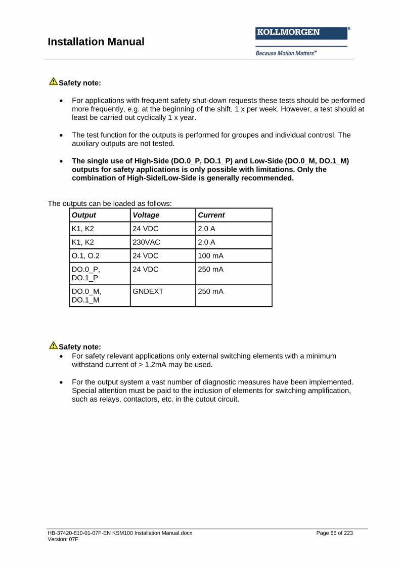
Installation Manual
HB-37420-810-01-07F-EN KSM100 Installation Manual.docx Page 66 of 223 Version: 07F
Safety note:
For applications with frequent safety shut-down requests these tests should be performed more frequently, e.g. at the beginning of the shift, 1 x per week. However, a test should at least be carried out cyclically 1 x year.
The test function for the outputs is performed for groupes and individual controsl. The auxiliary outputs are not tested.
The single use of High-Side (DO.0_P, DO.1_P) and Low-Side (DO.0_M, DO.1_M) outputs for safety applications is only possible with limitations. Only the combination of High-Side/Low-Side is generally recommended.
The outputs can be loaded as follows:
Output Voltage Current
K1, K2 24 VDC 2.0 A
K1, K2 230VAC 2.0 A
O.1, O.2 24 VDC 100 mA
DO.0_P, DO.1_P
24 VDC 250 mA
DO.0_M, DO.1_M
GNDEXT 250 mA
Safety note:
For safety relevant applications only external switching elements with a minimum withstand current of > 1.2mA may be used.
For the output system a vast number of diagnostic measures have been implemented. Special attention must be paid to the inclusion of elements for switching amplification, such as relays, contactors, etc. in the cutout circuit.
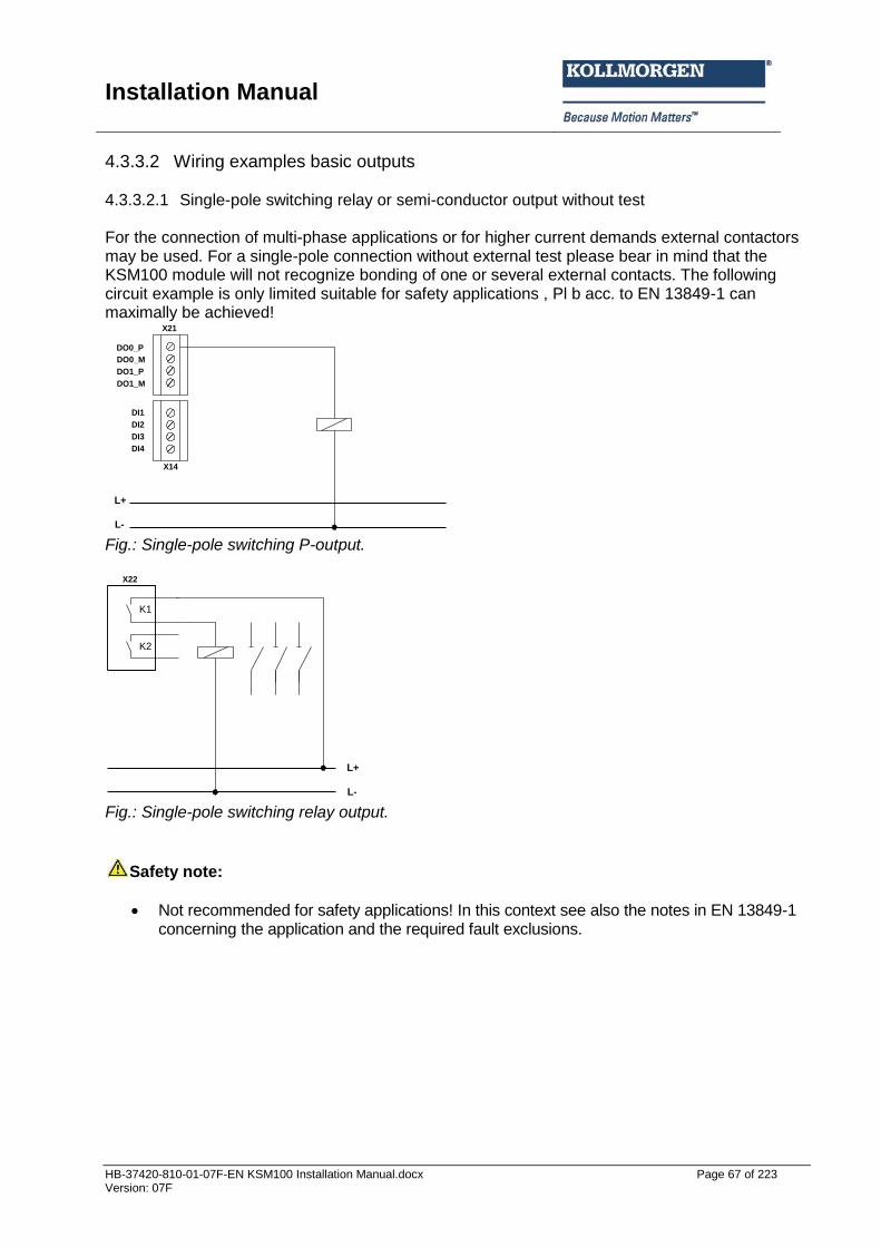
Installation Manual
HB-37420-810-01-07F-EN KSM100 Installation Manual.docx Page 67 of 223 Version: 07F
4.3.3.2 Wiring examples basic outputs 4.3.3.2.1 Single-pole switching relay or semi-conductor output without test For the connection of multi-phase applications or for higher current demands external contactors may be used. For a single-pole connection without external test please bear in mind that the KSM100 module will not recognize bonding of one or several external contacts. The following circuit example is only limited suitable for safety applications , Pl b acc. to EN 13849-1 can maximally be achieved!
DO0_P
X21
X14
DO0_M
DO1_P
DO1_M
DI1
DI2
DI3
DI4
L+
L- Fig.: Single-pole switching P-output.
K1
K2
L+
L-
X22
Fig.: Single-pole switching relay output.
Safety note:
Not recommended for safety applications! In this context see also the notes in EN 13849-1 concerning the application and the required fault exclusions.
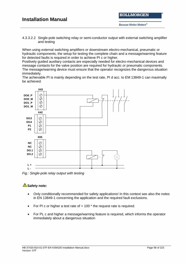
Installation Manual
HB-37420-810-01-07F-EN KSM100 Installation Manual.docx Page 68 of 223 Version: 07F
4.3.3.2.2 Single-pole switching relay or semi-conductor output with external switching amplifier
and testing
When using external switching amplifiers or downstream electro-mechanical, pneumatic or hydraulic components, the setup for testing the complete chain and a message/warning feature for detected faults is required in order to achieve PI c or higher. Positively guided auxiliary contacts are especially needed for electro-mechanical devices and message contacts for the valve position are required for hydraulic or pneumatic components. The message/warning device must ensure that the operator recognizes the dangerous situation immediately. The achievable PI is mainly depending on the test rate, PI d acc. to EM 13849-1 can maximally be achieved.
DO0_P
X43
X42
DO0_M
DO1_P
DO1_M
NC
NC
DO.1
DO.2
X65
DI13
DI14
P1
P2
L +
L -
Fig.: Single-pole relay output with testing
Safety note:
Only conditionally recommended for safety applications! In this context see also the notes in EN 13849-1 concerning the application and the required fault exclusions.
For PI c or higher a test rate of > 100 * the request rate is required.
For PL c and higher a message/warning feature is required, which informs the operator immediately about a dangerous situation
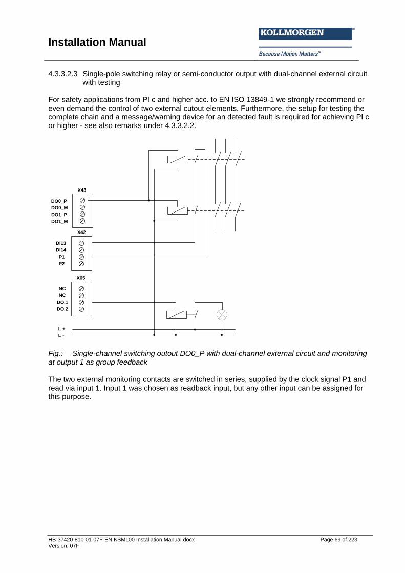
Installation Manual
HB-37420-810-01-07F-EN KSM100 Installation Manual.docx Page 69 of 223 Version: 07F
4.3.3.2.3 Single-pole switching relay or semi-conductor output with dual-channel external circuit with testing
For safety applications from PI c and higher acc. to EN ISO 13849-1 we strongly recommend or even demand the control of two external cutout elements. Furthermore, the setup for testing the complete chain and a message/warning device for an detected fault is required for achieving PI c or higher - see also remarks under 4.3.3.2.2.
DO0_P
X43
X42
DO0_M
DO1_P
DO1_M
NC
NC
DO.1
DO.2
X65
DI13
DI14
P1
P2
L +
L - Fig.: Single-channel switching outout DO0_P with dual-channel external circuit and monitoring at output 1 as group feedback The two external monitoring contacts are switched in series, supplied by the clock signal P1 and read via input 1. Input 1 was chosen as readback input, but any other input can be assigned for this purpose.
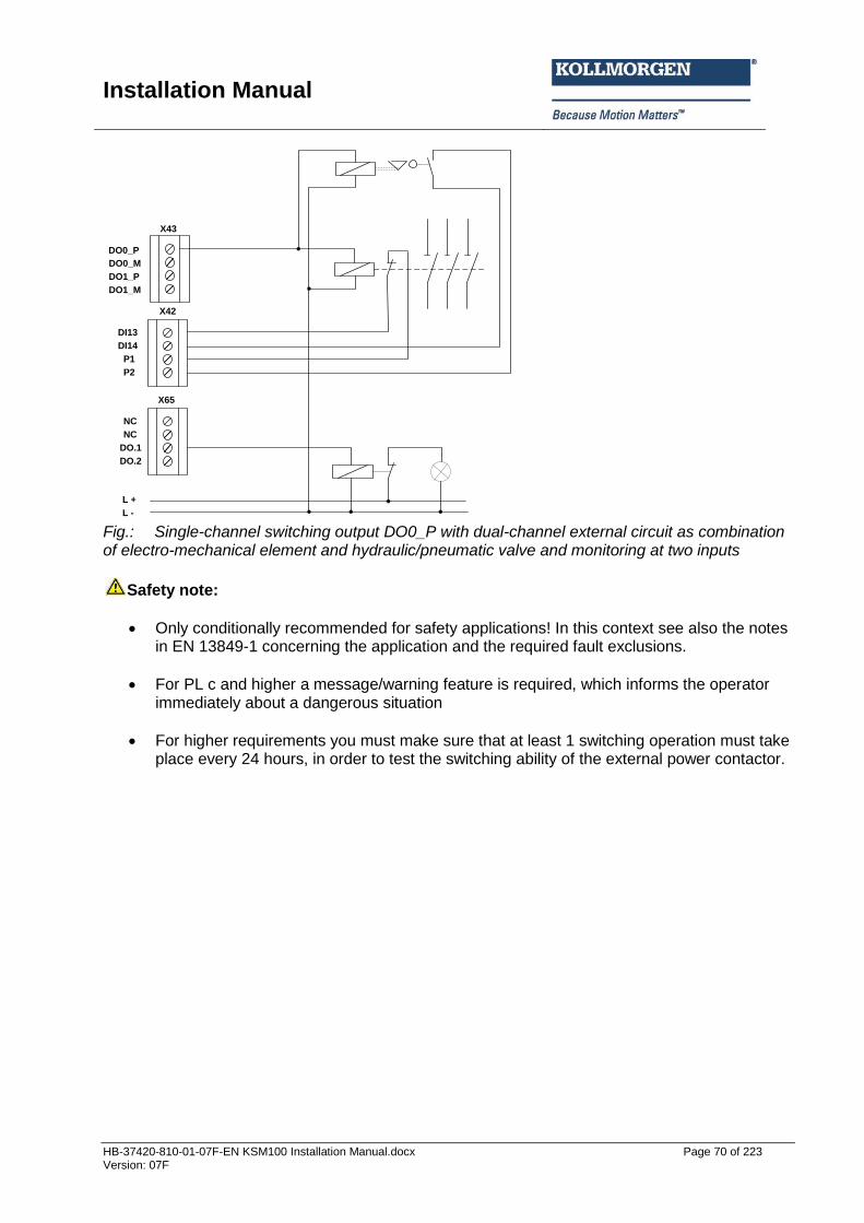
Installation Manual
HB-37420-810-01-07F-EN KSM100 Installation Manual.docx Page 70 of 223 Version: 07F
DO0_P
X43
X42
DO0_M
DO1_P
DO1_M
NC
NC
DO.1
DO.2
X65
DI13
DI14
P1
P2
L +
L - Fig.: Single-channel switching output DO0_P with dual-channel external circuit as combination of electro-mechanical element and hydraulic/pneumatic valve and monitoring at two inputs
Safety note:
Only conditionally recommended for safety applications! In this context see also the notes in EN 13849-1 concerning the application and the required fault exclusions.
For PL c and higher a message/warning feature is required, which informs the operator immediately about a dangerous situation
For higher requirements you must make sure that at least 1 switching operation must take place every 24 hours, in order to test the switching ability of the external power contactor.
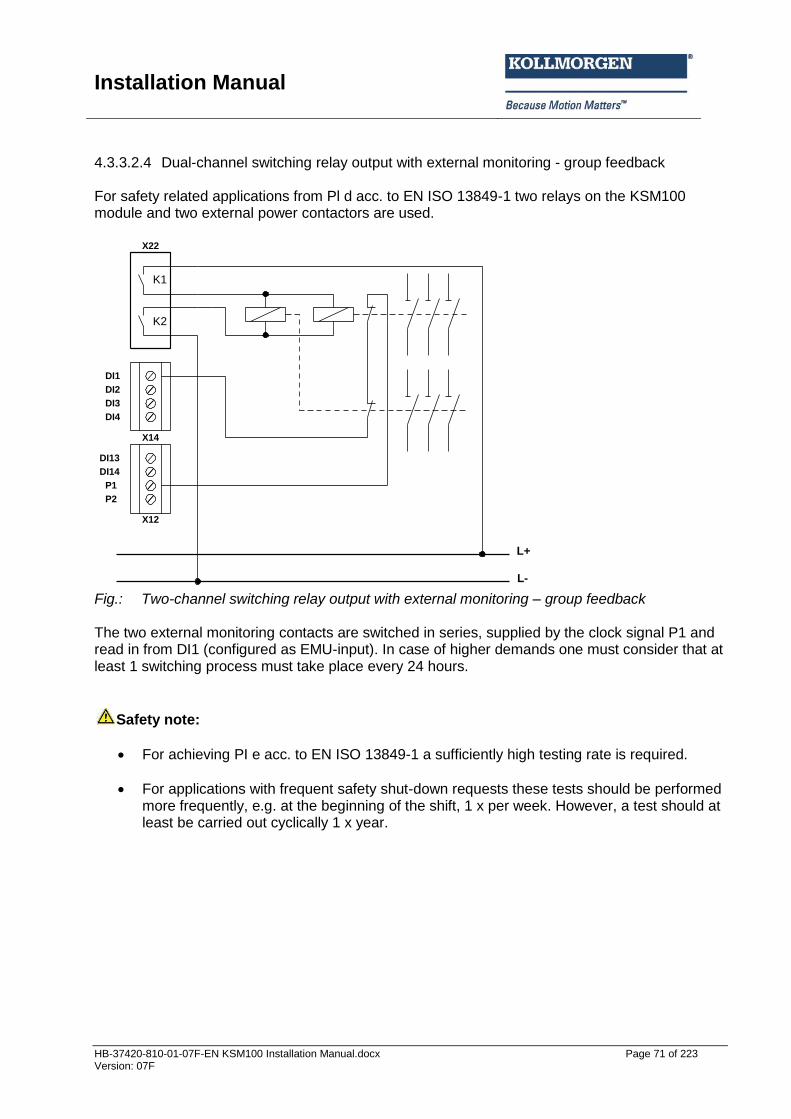
Installation Manual
HB-37420-810-01-07F-EN KSM100 Installation Manual.docx Page 71 of 223 Version: 07F
4.3.3.2.4 Dual-channel switching relay output with external monitoring - group feedback For safety related applications from Pl d acc. to EN ISO 13849-1 two relays on the KSM100 module and two external power contactors are used.
K1
K2
L+
L-
X22
X14
DI1
DI2
DI3
DI4
DI13
DI14
P1
P2
X12
Fig.: Two-channel switching relay output with external monitoring – group feedback The two external monitoring contacts are switched in series, supplied by the clock signal P1 and read in from DI1 (configured as EMU-input). In case of higher demands one must consider that at least 1 switching process must take place every 24 hours.
Safety note:
For achieving PI e acc. to EN ISO 13849-1 a sufficiently high testing rate is required.
For applications with frequent safety shut-down requests these tests should be performed more frequently, e.g. at the beginning of the shift, 1 x per week. However, a test should at least be carried out cyclically 1 x year.
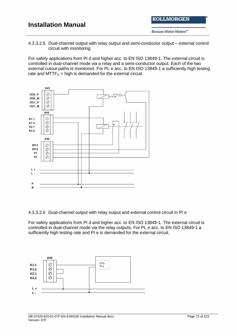
Installation Manual
HB-37420-810-01-07F-EN KSM100 Installation Manual.docx Page 72 of 223 Version: 07F
4.3.3.2.5 Dual-channel output with relay output and semi-conductor output – external control circuit with monitoring
For safety applications from PI d and higher acc. to EN ISO 13849-1. The external circuit is controlled in dual-channel mode via a relay and a semi-conductor output. Each of the two external cutout paths is monitored. For PL e acc. to EN ISO 13849-1 a sufficiently high testing rate and MTTFD = high is demanded for the external circuit.
4.3.3.2.6 Dual-channel output with relay output and external control circuit in PI e For safety applications from PI d and higher acc. to EN ISO 13849-1. The external circuit is controlled in dual-channel mode via the relay outputs. For PL e acc. to EN ISO 13849-1 a sufficiently high testing rate and PI e is demanded for the external circuit.
L +
L -
K1.1
X44
K1.2
K2.1
K2.2
STO
Pl e
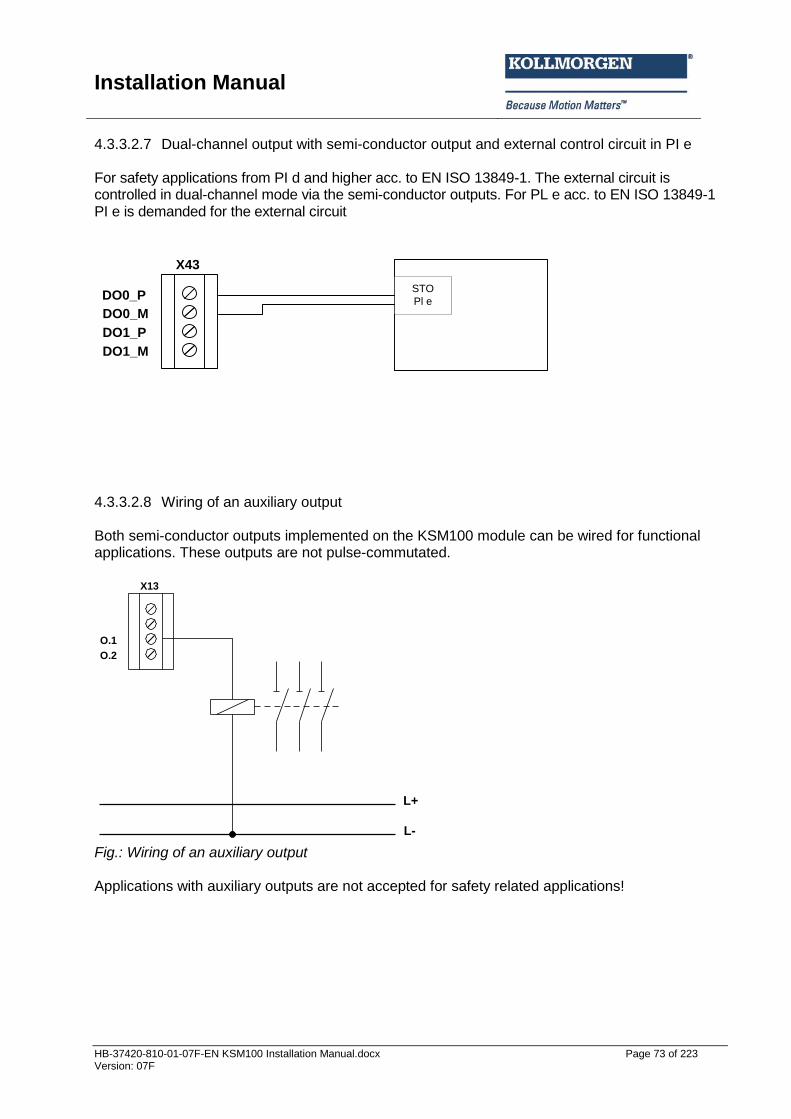
Installation Manual
HB-37420-810-01-07F-EN KSM100 Installation Manual.docx Page 73 of 223 Version: 07F
4.3.3.2.7 Dual-channel output with semi-conductor output and external control circuit in PI e For safety applications from PI d and higher acc. to EN ISO 13849-1. The external circuit is controlled in dual-channel mode via the semi-conductor outputs. For PL e acc. to EN ISO 13849-1 PI e is demanded for the external circuit
STO
Pl eDO0_P
X43
DO0_M
DO1_P
DO1_M
4.3.3.2.8 Wiring of an auxiliary output Both semi-conductor outputs implemented on the KSM100 module can be wired for functional applications. These outputs are not pulse-commutated.
L+
L-
O.1
O.2
X13
Fig.: Wiring of an auxiliary output Applications with auxiliary outputs are not accepted for safety related applications!
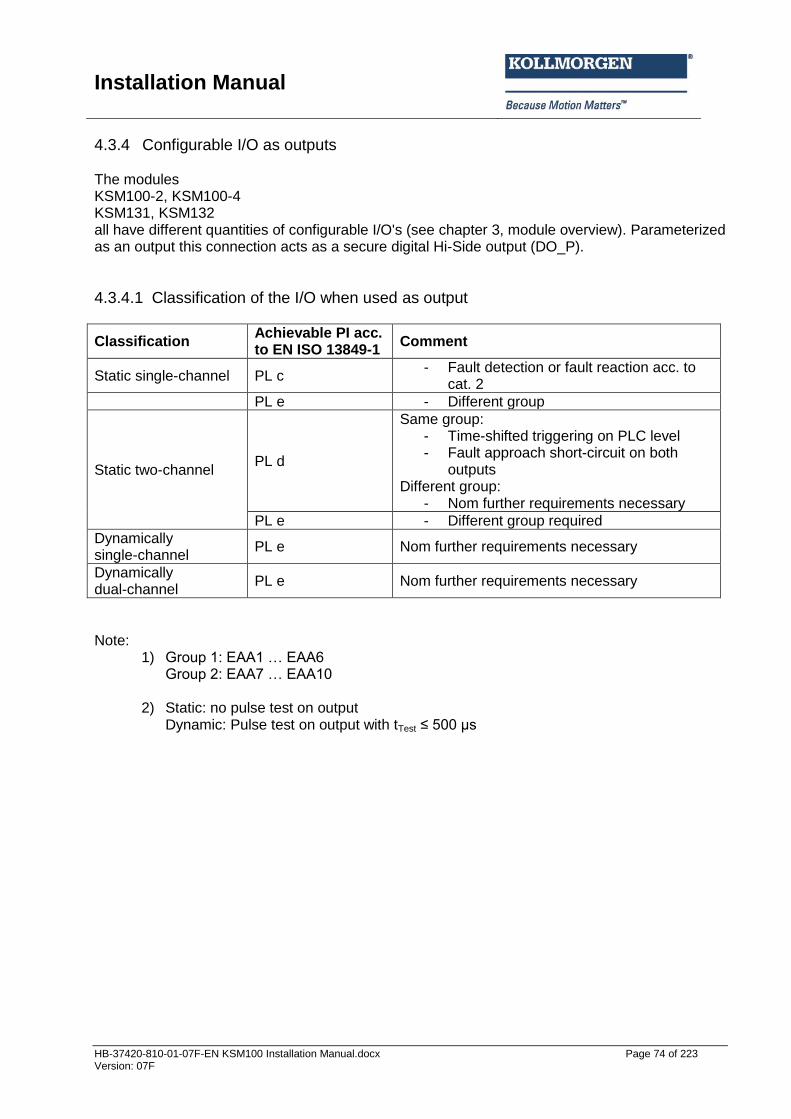
Installation Manual
HB-37420-810-01-07F-EN KSM100 Installation Manual.docx Page 74 of 223 Version: 07F
4.3.4 Configurable I/O as outputs The modules KSM100-2, KSM100-4 KSM131, KSM132 all have different quantities of configurable I/O's (see chapter 3, module overview). Parameterized as an output this connection acts as a secure digital Hi-Side output (DO_P).
4.3.4.1 Classification of the I/O when used as output
Classification Achievable PI acc. to EN ISO 13849-1
Comment
Static single-channel PL c - Fault detection or fault reaction acc. to
cat. 2
PL e - Different group
Static two-channel PL d
Same group: - Time-shifted triggering on PLC level - Fault approach short-circuit on both
outputs Different group:
- Nom further requirements necessary
PL e - Different group required
Dynamically single-channel
PL e Nom further requirements necessary
Dynamically dual-channel
PL e Nom further requirements necessary
Note:
1) Group 1: EAA1 … EAA6 Group 2: EAA7 … EAA10
2) Static: no pulse test on output Dynamic: Pulse test on output with tTest ≤ 500 µs
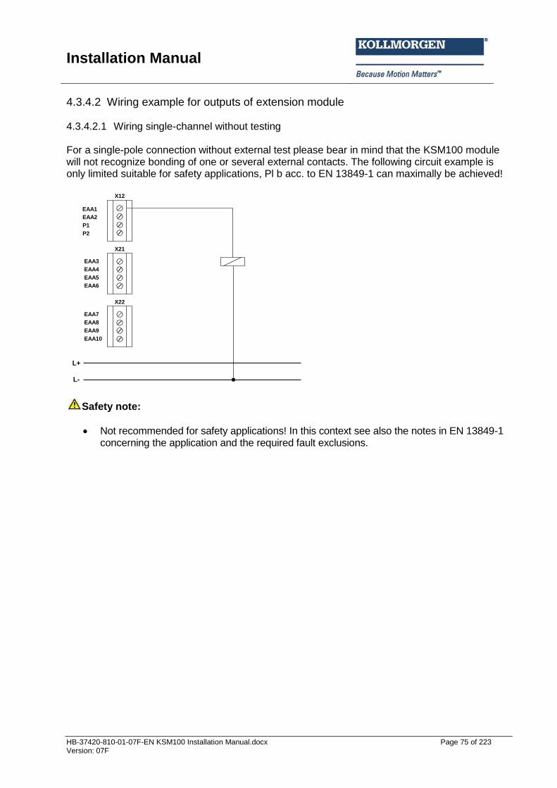
Installation Manual
HB-37420-810-01-07F-EN KSM100 Installation Manual.docx Page 75 of 223 Version: 07F
4.3.4.2 Wiring example for outputs of extension module 4.3.4.2.1 Wiring single-channel without testing For a single-pole connection without external test please bear in mind that the KSM100 module will not recognize bonding of one or several external contacts. The following circuit example is only limited suitable for safety applications, Pl b acc. to EN 13849-1 can maximally be achieved!
EAA1
X12
X21
EAA2
P1
P2
L+
L-
EAA3
EAA4
EAA5
EAA6
EAA7
EAA8
EAA9
EAA10
X22
Safety note:
Not recommended for safety applications! In this context see also the notes in EN 13849-1 concerning the application and the required fault exclusions.
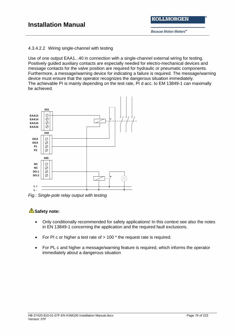
Installation Manual
HB-37420-810-01-07F-EN KSM100 Installation Manual.docx Page 76 of 223 Version: 07F
4.3.4.2.2 Wiring single-channel with testing
Use of one output EAA1...40 in connection with a single-channel external wiring for testing. Positively guided auxiliary contacts are especially needed for electro-mechanical devices and message contacts for the valve position are required for hydraulic or pneumatic components. Furthermore, a message/warning device for indicating a failure is required. The message/warning device must ensure that the operator recognizes the dangerous situation immediately. The achievable PI is mainly depending on the test rate, PI d acc. to EM 13849-1 can maximally be achieved.
EAA13
X51
X42
EAA14
EAA15
EAA16
NC
NC
DO.1
DO.2
X65
DI13
DI14
P1
P2
L +
L - Fig.: Single-pole relay output with testing
Safety note:
Only conditionally recommended for safety applications! In this context see also the notes in EN 13849-1 concerning the application and the required fault exclusions.
For PI c or higher a test rate of > 100 * the request rate is required.
For PL c and higher a message/warning feature is required, which informs the operator immediately about a dangerous situation
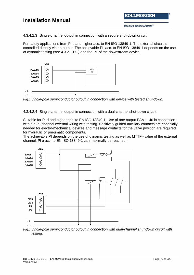
Installation Manual
HB-37420-810-01-07F-EN KSM100 Installation Manual.docx Page 77 of 223 Version: 07F
4.3.4.2.3 Single-channel output in connection with a secure shut-down circuit For safety applications from PI c and higher acc. to EN ISO 13849-1. The external circuit is controlled directly via an output. The achievable PL acc. to EN ISO 13849-1 depends on the use of dynamic testing (see 4.3.2.1 DC) and the PL of the downstream device.
STO
Pl eEAA13
X51
EAA14
EAA15
EAA16
L +
L - Fig.: Single-pole semi-conductor output in connection with device with tested shut-down. 4.3.4.2.4 Single-channel output in connection with a dual-channel shut-down circuit Suitable for PI d and higher acc. to EN ISO 13849-1. Use of one output EAA1...40 in connection with a dual-channel external wiring with testing. Positively guided auxiliary contacts are especially needed for electro-mechanical devices and message contacts for the valve position are required for hydraulic or pneumatic components. The achievable PI depends on the use of dynamic testing as well as MTTFD-value of the external channel. Pl e acc. to EN ISO 13849-1 can maximally be reached.
X42
DI13
DI14
P1
P2
L +
L -
EAA13
X51
EAA14
EAA15
EAA16
Fig.: Single-pole semi-conductor output in connection with dual-channel shut-down circuit with
testing.
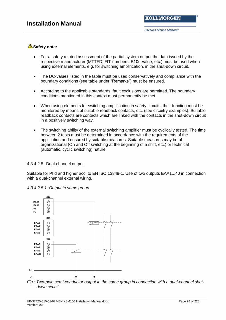
Installation Manual
HB-37420-810-01-07F-EN KSM100 Installation Manual.docx Page 78 of 223 Version: 07F
Safety note:
For a safety related assessment of the partial system output the data issued by the respective manufacturer (MTTFD, FIT-numbers, B10d-value, etc.) must be used when using external elements, e.g. for switching amplification, in the shut-down circuit.
The DC-values listed in the table must be used conservatively and compliance with the boundary conditions (see table under “Remarks”) must be ensured.
According to the applicable standards, fault exclusions are permitted. The boundary conditions mentioned in this context must permanently be met.
When using elements for switching amplification in safety circuits, their function must be monitored by means of suitable readback contacts, etc. (see circuitry examples). Suitable readback contacts are contacts which are linked with the contacts in the shut-down circuit in a positively switching way.
The switching ability of the external switching amplifier must be cyclically tested. The time between 2 tests must be determined in accordance with the requirements of the application and ensured by suitable measures. Suitable measures may be of organizational (On and Off switching at the beginning of a shift, etc.) or technical (automatic, cyclic switching) nature.
4.3.4.2.5 Dual-channel output Suitable for PI d and higher acc. to EN ISO 13849-1. Use of two outputs EAA1...40 in connection with a dual-channel external wiring. 4.3.4.2.5.1 Output in same group
EAA1
X12
X21
EAA2
P1
P2
L+
L-
EAA3
EAA4
EAA5
EAA6
EAA7
EAA8
EAA9
EAA10
X22
Fig.: Two-pole semi-conductor output in the same group in connection with a dual-channel shut-
down circuit
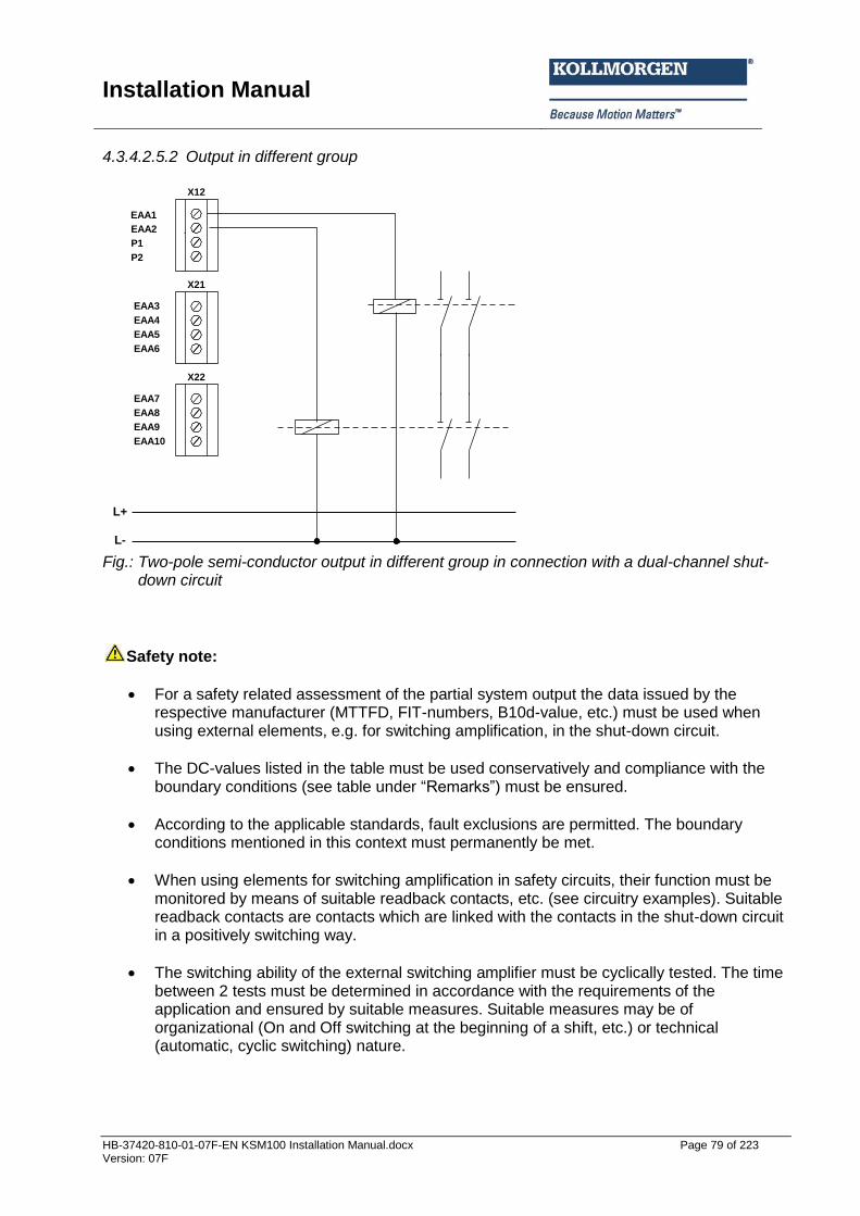
Installation Manual
HB-37420-810-01-07F-EN KSM100 Installation Manual.docx Page 79 of 223 Version: 07F
4.3.4.2.5.2 Output in different group
EAA1
X12
X21
EAA2
P1
P2
L+
L-
EAA3
EAA4
EAA5
EAA6
EAA7
EAA8
EAA9
EAA10
X22
Fig.: Two-pole semi-conductor output in different group in connection with a dual-channel shut-
down circuit
Safety note:
For a safety related assessment of the partial system output the data issued by the respective manufacturer (MTTFD, FIT-numbers, B10d-value, etc.) must be used when using external elements, e.g. for switching amplification, in the shut-down circuit.
The DC-values listed in the table must be used conservatively and compliance with the boundary conditions (see table under “Remarks”) must be ensured.
According to the applicable standards, fault exclusions are permitted. The boundary conditions mentioned in this context must permanently be met.
When using elements for switching amplification in safety circuits, their function must be monitored by means of suitable readback contacts, etc. (see circuitry examples). Suitable readback contacts are contacts which are linked with the contacts in the shut-down circuit in a positively switching way.
The switching ability of the external switching amplifier must be cyclically tested. The time between 2 tests must be determined in accordance with the requirements of the application and ensured by suitable measures. Suitable measures may be of organizational (On and Off switching at the beginning of a shift, etc.) or technical (automatic, cyclic switching) nature.
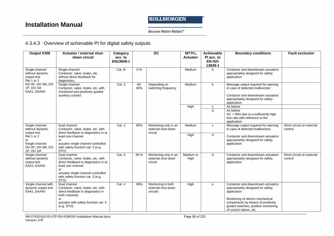
Installation Manual
HB-37420-810-01-07F-EN KSM100 Installation Manual.docx Page 80 of 223 Version: 07F
4.3.4.3 Overview of achievable PI for digital safety outputs
Output KSM Actuator / external shut-down circuit
Category acc. to
EN13849-1
DC MTTFD Actuator
Achievable PI acc. to EN ISO 13849-1
Boundary conditions Fault exclusion
Single-channel without dynamic output test Rel 1 or 2 DO 0P, DO 0M, DO 1P, DO 1M EAA1..EAA40
Single-channel Contactor, valve, brake, etc. without direct feedback for diagnostics.
Cat. B 0 % Medium b Contactor and downstream actuators appropriately designed for safety application
Single-channel Contactor, valve, brake, etc. with monitored and positively guided auxiliary contact
Cat. 2 60-90%
Depending on switching frequency
Medium
b Message output required for warning in case of detected malfunction Contactor and downstream actuators appropriately designed for safety application
High c As before
d As before DC = 90% due to a sufficiently high test rate with reference to the application
Single-channel without dynamic output test Rel 1 or 2 or Single-channel DO 0P, DO 0M, DO 1P, DO 1M
Dual channel Contactor, valve, brake, etc. with direct feedback to diagnostics in at least one channel or actuator single channel controlled with safety function cat. 3 (e.g. STO)
Cat. 2 90% Monitoring only in an external shut-down circuit
Medium c Message output required for warning in case of detected malfunction Contactor and downstream actuators appropriately designed for safety application
Short circuit on external control
High d
Single-channel without dynamic output test EAA1..EAA40
Dual channel Contactor, valve, brake, etc. with direct feedback to diagnostics in at least one channel or actuator single channel controlled with safety function cat. 3 (e.g. STO)
Cat. 3 90 % Monitoring only in an external shut-down circuit
Medium or High
d Contactor and downstream actuators appropriately designed for safety application
Short circuit on external control
Single-channel with dynamic output test EAA1..EAA40
Dual channel Contactor, valve, brake, etc. with direct feedback to diagnostics in both channels or actuator with safety function cat. 4 (e.g. STO)
Cat. 4 99% Monitoring in both external shut-down circuits
High e Contactor and downstream actuators appropriately designed for safety application Monitoring of electro-mechanical components by means of positively guided switches, position monitoring of control valves, etc.
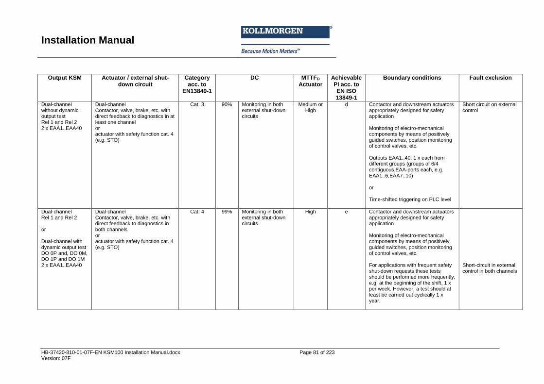
Installation Manual
HB-37420-810-01-07F-EN KSM100 Installation Manual.docx Page 81 of 223 Version: 07F
Output KSM Actuator / external shut-
down circuit Category
acc. to EN13849-1
DC MTTFD Actuator
Achievable PI acc. to EN ISO 13849-1
Boundary conditions Fault exclusion
Dual-channel without dynamic output test Rel 1 and Rel 2 2 x EAA1..EAA40
Dual-channel Contactor, valve, brake, etc. with direct feedback to diagnostics in at least one channel or actuator with safety function cat. 4 (e.g. STO)
Cat. 3 90% Monitoring in both external shut-down circuits
Medium or High
d Contactor and downstream actuators appropriately designed for safety application Monitoring of electro-mechanical components by means of positively guided switches, position monitoring of control valves, etc. Outputs EAA1..40, 1 x each from different groups (groups of 6/4 contiguous EAA-ports each, e.g. EAA1..6,EAA7..10) or Time-shifted triggering on PLC level
Short circuit on external control
Dual-channel Rel 1 and Rel 2 or Dual-channel with dynamic output test DO 0P and, DO 0M, DO 1P and DO 1M 2 x EAA1..EAA40
Dual-channel Contactor, valve, brake, etc. with direct feedback to diagnostics in both channels or actuator with safety function cat. 4 (e.g. STO)
Cat. 4 99% Monitoring in both external shut-down circuits
High e Contactor and downstream actuators appropriately designed for safety application Monitoring of electro-mechanical components by means of positively guided switches, position monitoring of control valves, etc. For applications with frequent safety shut-down requests these tests should be performed more frequently, e.g. at the beginning of the shift, 1 x per week. However, a test should at least be carried out cyclically 1 x year.
Short-circuit in external control in both channels
Installation Manual
HB-37420-810-01-07F-EN KSM100 Installation Manual.docx Page 82 of 223 Version: 07F
5 Connection and installation
5.1 General notes on installation Strictly follow the safety regulations when installing! Degree of protection IP52. Route all signal lines for the interfacing of digital inputs and contact monitoring separately. In any case isolate 230 VAC voltages from low voltage lines, if these voltages are used in connection with the application. The cable lengths for digital inputs and outputs must normally not exceed 30m. If the cable lengths exceeds 30m you must apply appropriate measures for fault exclusion concerning impermissible overvoltage. Appropriate measures include e.g. lightning protection for outdoor lines, overvoltage protection of the indoor system, protected routing of cables. Measures concerning the electromagnetic compatibility (EMC) The KSM100 module is intended for use in the drive environment and meets the EMC-requirements mentioned above. It is also assumed that the electromagnetic compatibility of the overall system is ensured by application of appropriate measures.
Safety note:
Electric power supply lines of the KSM100 and “discontinuous-action lines” of the power converter must be isolated from each other.
Signal lines and power lines of the power converter must be routed through separate cable ducts. The distance between the cable ducts should be minimum 10 mm.
Only shielded cables must be used to connect the position and speed sensors. The signal transmission cable must be RS-485-standard compliant (lines twisted in pairs).
Care must be taken to ensure that the shielding is correctly connected in the 9-pin SUB-D plugs of the position and speed sensors. Only metal or metal coated plugs are permitted.
The shielding on the sensor side must comply with appropriate methods.
EMC-compliant installation of the power converter technology in the environment of the KSM100 module must be assured. Special attention must be paid to the routing of cables, the shielding of motor cables and the connection of the braking resistor. Strict compliance with the installation instructions of the power converter manufacturer is mandatory.
All contactors in the environment of the power converter must be equipped with appropriate suppressor circuits.
Suitable measures to protect against overvoltages must be applied.

Installation Manual
HB-37420-810-01-07F-EN KSM100 Installation Manual.docx Page 83 of 223 Version: 07F
5.2 Installation and assembly of the KSM100 module The module is solely to be installed in control cabinets with a degree of protection of at least IP54. The modules must be vertically fastened on a top hat rail The ventilation slots must be kept unobstructed, to ensure adequate air circulation inside the module.
5.3 Installation of backplane bus system Mounting several KSM100 modules (KSM100-1, KSM100-2, KSM100-4) on one top hat rail in connection with the backplane bus system is also possible. These modules can be combined with a communication extension. In this case the backplane bus system needs to be configured by Kollmorgen when placing the order and delivered in accordance with the application in question. The backplane bus system consists of a 5-pin plug connector with snap-in contacts. In these plug connectors all 5 contacts are equipped by standard. In this case the component is not specially marked. On a second variant of the plug connector only 3 contacts are equipped. Note: Expansion modules have no own power supply unit and depend on a DC power supply via the backplane bus system. Basic modules (KSM100-1, KSM100-2, KSM100-4) are equipped with a reinforced power supply unit and always feed in to the backplane bus. There are two different types of backplane bus connectors:
TB1: Standard design (all contacts are present)
TB2: Circuit breaker design (The two live conductors are not present and are marked with a green dot.
Using the backplane bus connector TB1: The backplane bus connector TB1 can only be installed in connection with expansion modules without their own power supply. Connection of several standalone modules is not possible. Using the backplane bus connector TB2: The backplane bus connector TB2 is used for combining several base modules with expansion modules. A detailed description can be found under point 4.3.1.
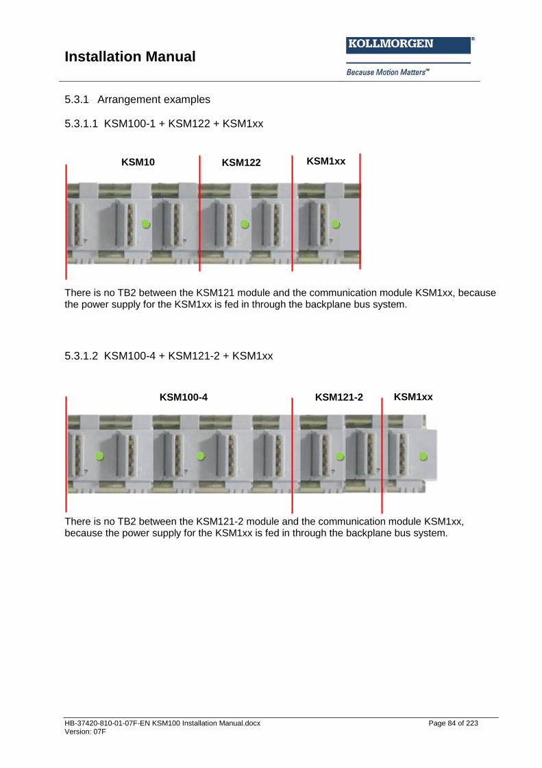
Installation Manual
HB-37420-810-01-07F-EN KSM100 Installation Manual.docx Page 84 of 223 Version: 07F
5.3.1 Arrangement examples
5.3.1.1 KSM100-1 + KSM122 + KSM1xx
There is no TB2 between the KSM121 module and the communication module KSM1xx, because the power supply for the KSM1xx is fed in through the backplane bus system.
5.3.1.2 KSM100-4 + KSM121-2 + KSM1xx
There is no TB2 between the KSM121-2 module and the communication module KSM1xx, because the power supply for the KSM1xx is fed in through the backplane bus system.
KSM1xx KSM122 KSM10
0-1
KSM100-4 KSM121-2 KSM1xx
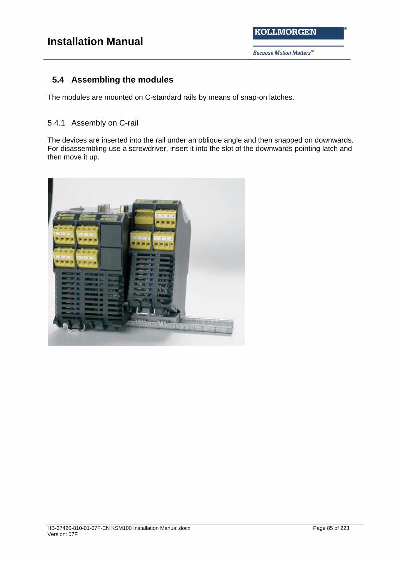
Installation Manual
HB-37420-810-01-07F-EN KSM100 Installation Manual.docx Page 85 of 223 Version: 07F
5.4 Assembling the modules The modules are mounted on C-standard rails by means of snap-on latches.
5.4.1 Assembly on C-rail The devices are inserted into the rail under an oblique angle and then snapped on downwards. For disassembling use a screwdriver, insert it into the slot of the downwards pointing latch and then move it up.
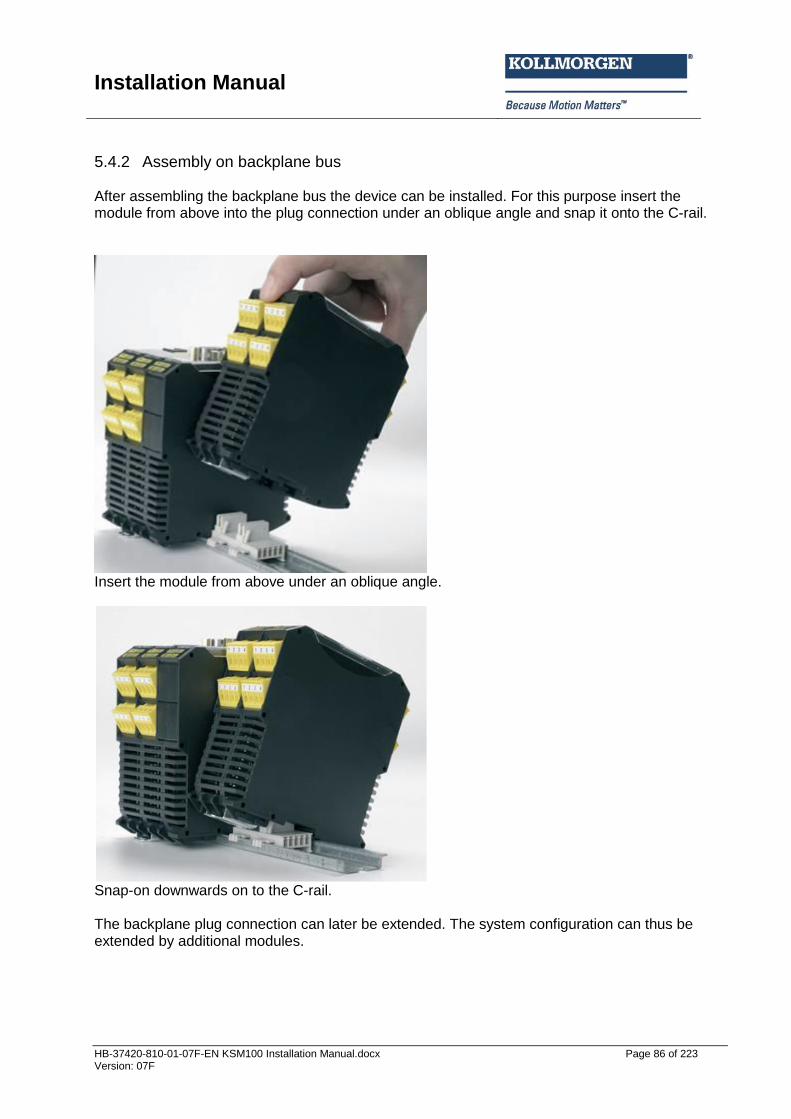
Installation Manual
HB-37420-810-01-07F-EN KSM100 Installation Manual.docx Page 86 of 223 Version: 07F
5.4.2 Assembly on backplane bus After assembling the backplane bus the device can be installed. For this purpose insert the module from above into the plug connection under an oblique angle and snap it onto the C-rail.
Insert the module from above under an oblique angle.
Snap-on downwards on to the C-rail. The backplane plug connection can later be extended. The system configuration can thus be extended by additional modules.

Installation Manual
HB-37420-810-01-07F-EN KSM100 Installation Manual.docx Page 87 of 223 Version: 07F
Snap the backplane bus element into the C-rail and insert it into the counter-piece by sliding it sideways.
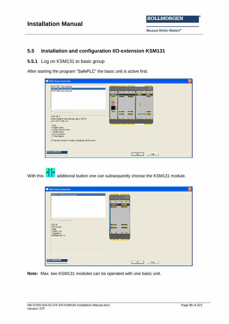
Installation Manual
HB-37420-810-01-07F-EN KSM100 Installation Manual.docx Page 88 of 223 Version: 07F
5.5 Installation and configuration I/O-extension KSM131
5.5.1 Log on KSM131 to basic group After starting the program “SafePLC” the basic unit is active first.
With this additional button one can subsequently choose the KSM131 module.
Note: Max. two KSM131 modules can be operated with one basic unit.
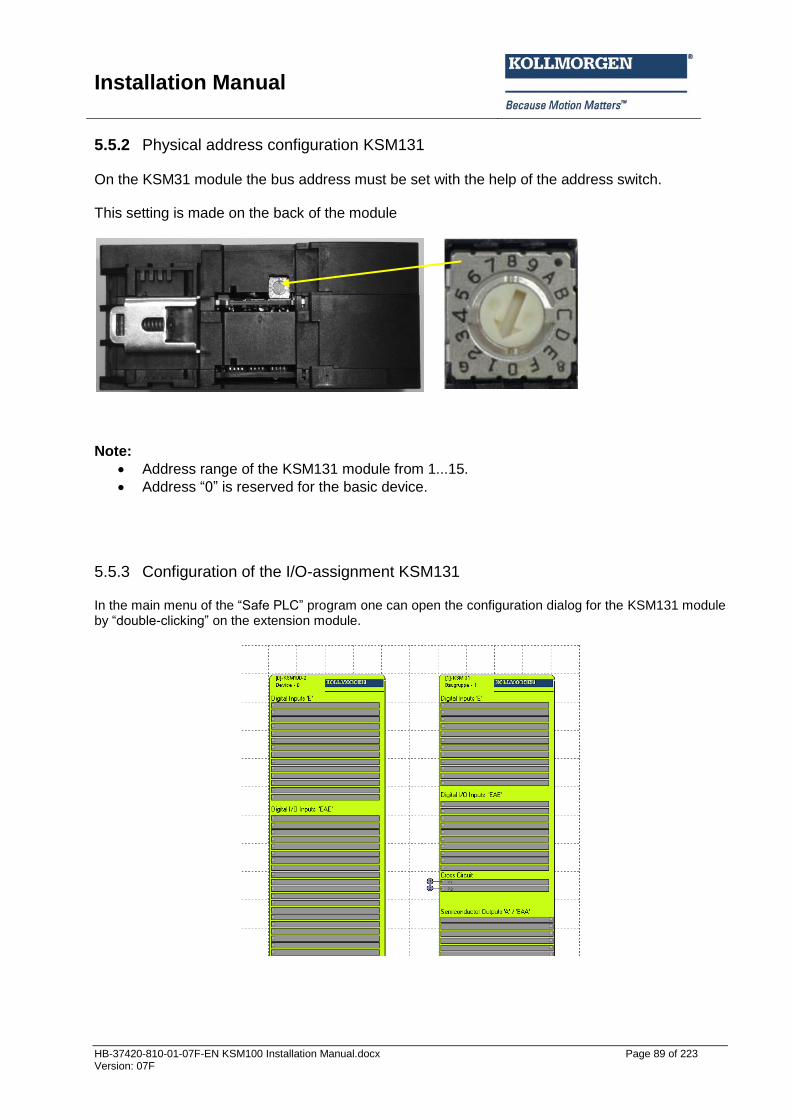
Installation Manual
HB-37420-810-01-07F-EN KSM100 Installation Manual.docx Page 89 of 223 Version: 07F
5.5.2 Physical address configuration KSM131 On the KSM31 module the bus address must be set with the help of the address switch. This setting is made on the back of the module
Note:
Address range of the KSM131 module from 1...15.
Address “0” is reserved for the basic device.
5.5.3 Configuration of the I/O-assignment KSM131 In the main menu of the “Safe PLC” program one can open the configuration dialog for the KSM131 module by “double-clicking” on the extension module.
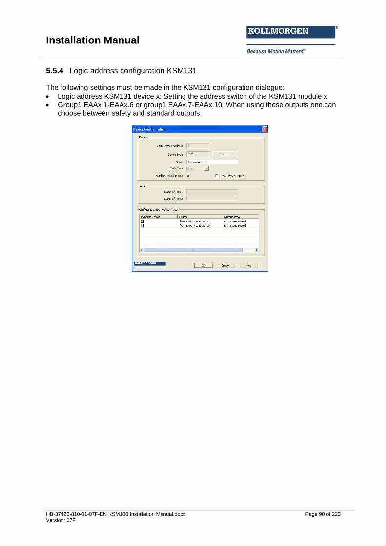
Installation Manual
HB-37420-810-01-07F-EN KSM100 Installation Manual.docx Page 90 of 223 Version: 07F
5.5.4 Logic address configuration KSM131 The following settings must be made in the KSM131 configuration dialogue:
Logic address KSM131 device x: Setting the address switch of the KSM131 module x
Group1 EAAx.1-EAAx.6 or group1 EAAx.7-EAAx.10: When using these outputs one can choose between safety and standard outputs.
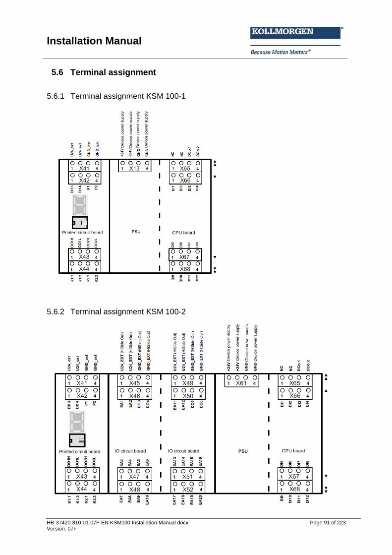
Installation Manual
HB-37420-810-01-07F-EN KSM100 Installation Manual.docx Page 91 of 223 Version: 07F
5.6 Terminal assignment
5.6.1 Terminal assignment KSM 100-1
5.6.2 Terminal assignment KSM 100-2
CPU board Printed circuit board
CPU board Printed circuit board IO circuit board IO circuit board
Devic
e p
ow
er
sup
ply
Devic
e p
ow
er
sup
ply
Devic
e p
ow
er
sup
ply
Devic
e p
ow
er
sup
ply
Devic
e p
ow
er
sup
ply
Devic
e p
ow
er
sup
ply
Devic
e p
ow
er
sup
ply
Devic
e p
ow
er
sup
ply
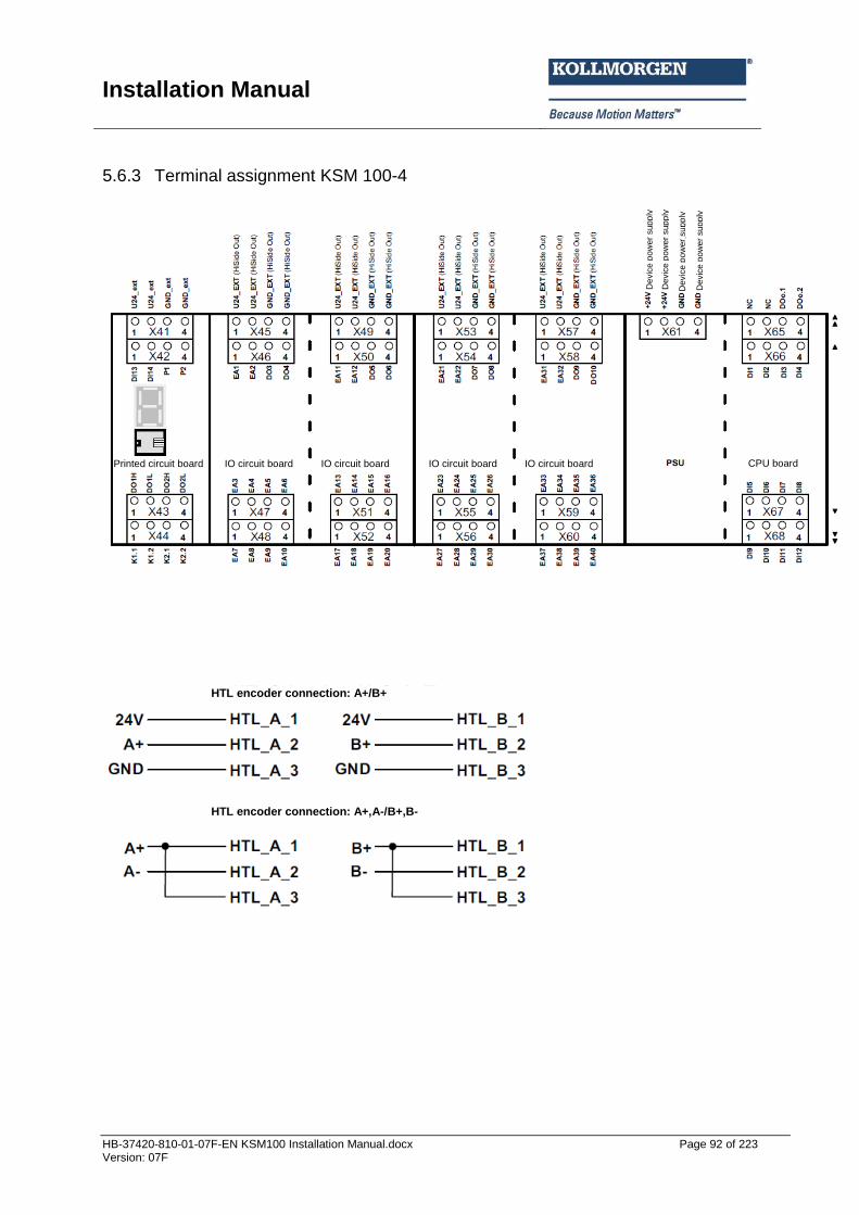
Installation Manual
HB-37420-810-01-07F-EN KSM100 Installation Manual.docx Page 92 of 223 Version: 07F
5.6.3 Terminal assignment KSM 100-4
Printed circuit board IO circuit board IO circuit board IO circuit board IO circuit board
Devic
e p
ow
er
sup
ply
Devic
e p
ow
er
sup
ply
Devic
e p
ow
er
sup
ply
Devic
e p
ow
er
sup
ply
HTL encoder connection: A+/B+
HTL encoder connection: A+,A-/B+,B-
CPU board
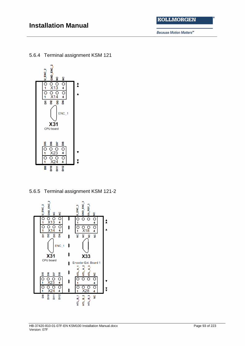
Installation Manual
HB-37420-810-01-07F-EN KSM100 Installation Manual.docx Page 93 of 223 Version: 07F
5.6.4 Terminal assignment KSM 121
5.6.5 Terminal assignment KSM 121-2
CPU board
CPU board
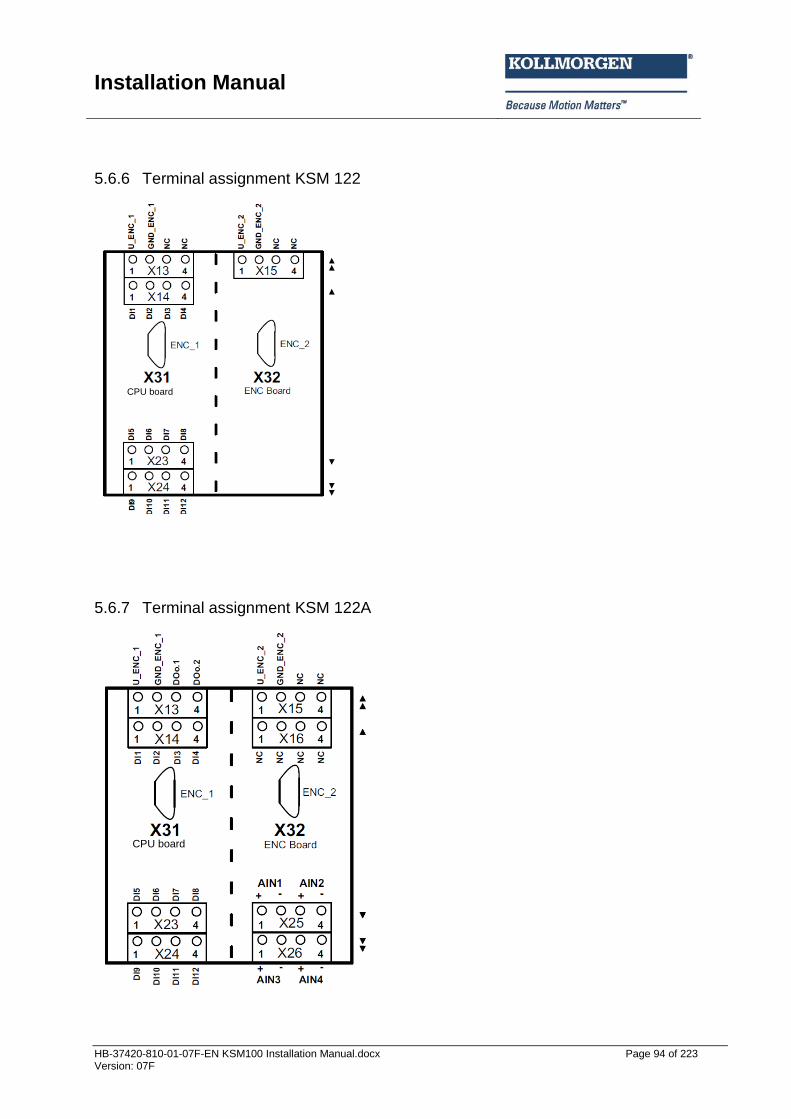
Installation Manual
HB-37420-810-01-07F-EN KSM100 Installation Manual.docx Page 94 of 223 Version: 07F
5.6.6 Terminal assignment KSM 122
5.6.7 Terminal assignment KSM 122A
CPU board
CPU board
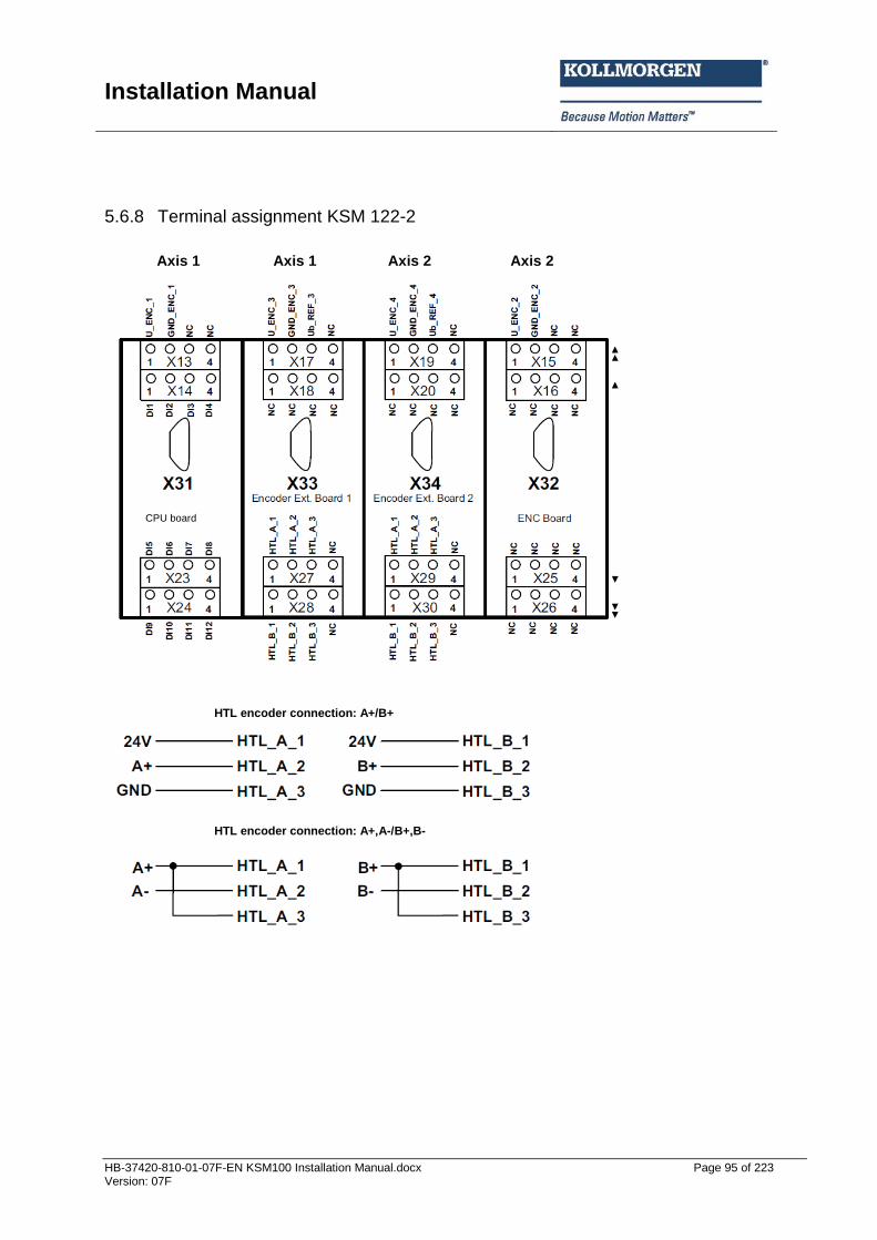
Installation Manual
HB-37420-810-01-07F-EN KSM100 Installation Manual.docx Page 95 of 223 Version: 07F
5.6.8 Terminal assignment KSM 122-2
Axis 1 Axis 2 Axis 2 Axis 1
CPU board
HTL encoder connection: A+/B+
HTL encoder connection: A+,A-/B+,B-
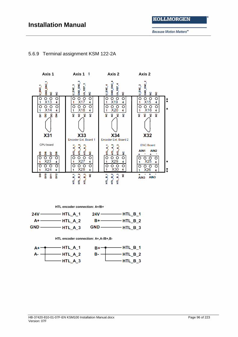
Installation Manual
HB-37420-810-01-07F-EN KSM100 Installation Manual.docx Page 96 of 223 Version: 07F
5.6.9 Terminal assignment KSM 122-2A
Axis 1 Axis 2 Axis 1 Axis 2
CPU board
HTL encoder connection: A+/B+
HTL encoder connection: A+,A-/B+,B-
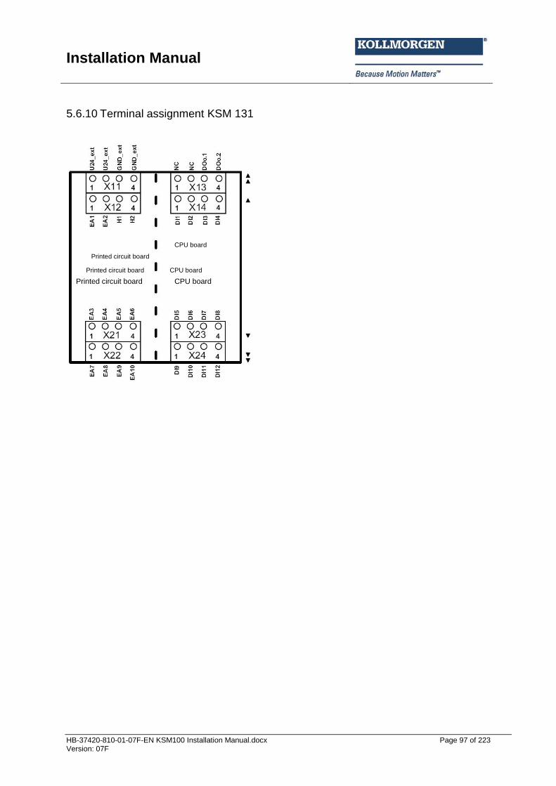
Installation Manual
HB-37420-810-01-07F-EN KSM100 Installation Manual.docx Page 97 of 223 Version: 07F
5.6.10 Terminal assignment KSM 131
CPU board
Printed circuit board
Printed circuit board CPU board
Printed circuit board CPU board
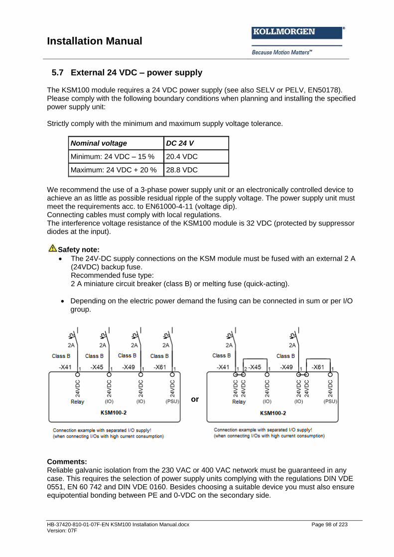
Installation Manual
HB-37420-810-01-07F-EN KSM100 Installation Manual.docx Page 98 of 223 Version: 07F
5.7 External 24 VDC – power supply The KSM100 module requires a 24 VDC power supply (see also SELV or PELV, EN50178). Please comply with the following boundary conditions when planning and installing the specified power supply unit: Strictly comply with the minimum and maximum supply voltage tolerance.
Nominal voltage DC 24 V
Minimum: 24 VDC – 15 % 20.4 VDC
Maximum: 24 VDC + 20 % 28.8 VDC
We recommend the use of a 3-phase power supply unit or an electronically controlled device to achieve an as little as possible residual ripple of the supply voltage. The power supply unit must meet the requirements acc. to EN61000-4-11 (voltage dip). Connecting cables must comply with local regulations. The interference voltage resistance of the KSM100 module is 32 VDC (protected by suppressor diodes at the input).
Safety note:
The 24V-DC supply connections on the KSM module must be fused with an external 2 A (24VDC) backup fuse. Recommended fuse type: 2 A miniature circuit breaker (class B) or melting fuse (quick-acting).
Depending on the electric power demand the fusing can be connected in sum or per I/O group.
Comments: Reliable galvanic isolation from the 230 VAC or 400 VAC network must be guaranteed in any case. This requires the selection of power supply units complying with the regulations DIN VDE 0551, EN 60 742 and DIN VDE 0160. Besides choosing a suitable device you must also ensure equipotential bonding between PE and 0-VDC on the secondary side.
or
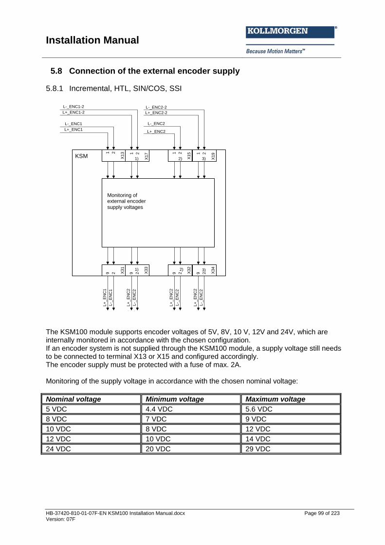
Installation Manual
HB-37420-810-01-07F-EN KSM100 Installation Manual.docx Page 99 of 223 Version: 07F
5.8 Connection of the external encoder supply
5.8.1 Incremental, HTL, SIN/COS, SSI
1)
SMX
Spannungs-
überwachung
der externen
Geber-
versorgungs-
spannungen
X1
51 2
L+_ENC1
L-_ENC1X
31
L+
_E
NC
1
L-_
EN
C1
9 2L+_ENC1-2
L-_ENC1-2
X3
3
L+
_E
NC
2
L-_
EN
C2
9 2
L+_ENC2
L-_ENC2
X3
2
L+
_E
NC
2
L-_
EN
C2
9 2
L+_ENC2-2
L-_ENC2-2
X3
4
L+
_E
NC
2
L-_
EN
C2
9 2
X1
31 2
X1
71 2
X1
51 2
X1
91 2
1)
1)
2)
2)
3)
3)
The KSM100 module supports encoder voltages of 5V, 8V, 10 V, 12V and 24V, which are internally monitored in accordance with the chosen configuration. If an encoder system is not supplied through the KSM100 module, a supply voltage still needs to be connected to terminal X13 or X15 and configured accordingly. The encoder supply must be protected with a fuse of max. 2A. Monitoring of the supply voltage in accordance with the chosen nominal voltage:
Nominal voltage Minimum voltage Maximum voltage
5 VDC 4.4 VDC 5.6 VDC
8 VDC 7 VDC 9 VDC
10 VDC 8 VDC 12 VDC
12 VDC 10 VDC 14 VDC
24 VDC 20 VDC 29 VDC
Monitoring of external encoder supply voltages
KSM
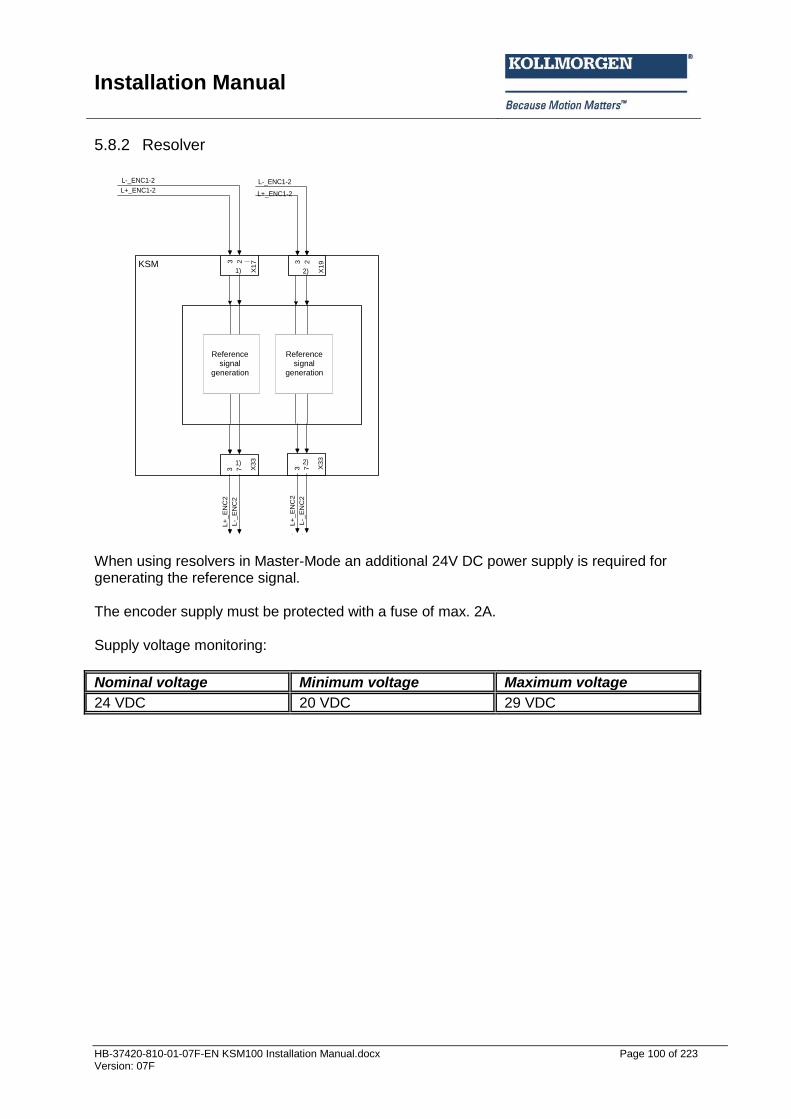
Installation Manual
HB-37420-810-01-07F-EN KSM100 Installation Manual.docx Page 100 of 223 Version: 07F
5.8.2 Resolver
1)
SMX
X1
51 2
L+_ENC1-2
L-_ENC1-2
X1
73 2
1) X1
51 2
L+_ENC1-2
L-_ENC1-2
X1
93 2
2)
X3
3
L+
_E
NC
2
L-_
EN
C2
3 7
1)
X3
3
L+
_E
NC
2
L-_
EN
C2
3 7
2)
Referenz-
Signal-
generierung
Referenz-
Signal-
generierung
When using resolvers in Master-Mode an additional 24V DC power supply is required for generating the reference signal. The encoder supply must be protected with a fuse of max. 2A. Supply voltage monitoring:
Nominal voltage Minimum voltage Maximum voltage
24 VDC 20 VDC 29 VDC
Reference signal
generation
Reference signal
generation
KSM

Installation Manual
HB-37420-810-01-07F-EN KSM100 Installation Manual.docx Page 101 of 223 Version: 07F
5.9 Connection of digital inputs The modules of the KSM100 system have 14 (KSM100-1/100-2/100-4) or 12 (KSM121, KSM121-2, KSM122, KSM122-2, KSM131) secure digital inputs. These are suitable for connecting single or two-channel signals with and without cycling, or without cross-shorting test. The connected signals must have a “High”-level of DC 24 V (DC +15 V...+ DC 30 V ) and a “Lo ”-level of (DC -3 V...DC +5 V, type 1 acc. to EN61131-2). 24 VDC; +5 V, Type1 acc. to EN61131-2 The inputs are provided with internal input filters. A device internal diagnostic function cyclically tests the correct function of the inputs including the input filters. A detected fault will set the KSM100 into an alarm status. At the same time all outputs of the KSM100 are rendered passive. Besides the actual signal inputs, the KSM100 module holds two clock inputs P1 and P2 available. The clock outputs are switching-type 24 VDC outputs. The clock outputs are solely intended for monitoring the digital inputs (DI1...DI14) and cannot be used for any other function within the application. The switching frequency is 125 Hz for each output. In the planning stage one must bear in mind that the outputs may only be loaded with a total current of max. 250 mA. Furthermore, approved OSSD-outputs can be connected to the inputs DI1-DI4 and DI9-DI14 without limitation Note:
Digital inputs DI5 to DI8 are not suitable for OSSDs, because there is no compliance with EN 61131-2 Type 2 requirements.
In case of single-channel use of the inputs, the achievable safety level must be limited to SIL 2 or PL d, if the safety function is demanded at regular intervals. A safety related use of the inputs is generally only intended in connection with the pulse outputs. If pulse outputs are not used, short circuits in the external wiring between different inputs and against the supply voltage for the KSM100 must be ruled out by external measures, appropriate routing of cables in particular. Each input of the KSM100 module can be configured individually for the following signal sources: Input assigned to pulse P1 Input assigned to pulse P2 Input assigned to continuous voltage DC 24 V

Installation Manual
HB-37420-810-01-07F-EN KSM100 Installation Manual.docx Page 102 of 223 Version: 07F
5.10 Connection of analog inputs With versions KSM122A with analog processing max. 2 analog signals can be securely processed. The analog inputs can be connected as follows:
min max
Voltage -7VDC +10VDC
Note: The module is equipped with the fixed loading resistor of 500Ohm as standard. This resistor can be omitted is required (voltage input).
5.11 Connection of position and speed sensors
5.11.1 General notes Depending on module type the KSM100 axis extension module (KSM121, KSM121-2, KSM122, KSM122-2) has (2/4) external encoder interfaces for the connection of industrial incremental and absolute encoders. The encoder interfaces can be configured as incremental, SIN/COS, absolute SSI-encoders or as Proxy. It is also possible to connect two incremental signal generating sensors (e.g. proximity switches) to the counting inputs of the KSM100 module. The signals must each be read in with normal and complementary track. IMPORTANT The voltage supply of the encoder system uses the dedicated terminals on the KSM100 module. This voltage is applied to the encoder plug and monitored by an internal diagnostic process. When the sensor is supplied with an external voltage, this voltage must be supplied through the encoder plug. The corresponding terminal (encoder supply voltage) on the KSM100 module remains unoccupied. If an external sensor voltage supply is not recirculated through the encoder plug, any failure of this supply must be included in the fault examination of the overall system. This, in particular, requires evidence that this fault is detected or can be excluded when the specified operating voltage of the overall system is fallen short of / exceeded. EMC - measures such as shielding etc. must be observed. The two encoders must be non-interacting to each other. This applies for both the electrical as well as the mechanical part. If both encoders are coupled to the facility to be monitored via common mechanical parts, the connection must be positively designed and should not have any parts that are susceptible to wear (chains, toothed belts, etc.). Should this be the case, additional monitoring features for the mechanical connection of the sensors (e.g. monitoring of a toothed belt) are required). In case of an active position processing at least one absolute value encoder must be used. When using two equivalent sensors one must make sure that the sensor with the higher resolution is configured as sensor 1 (process sensor) and the sensor with the lower resolution as sensor 2 (reference sensor).

Installation Manual
HB-37420-810-01-07F-EN KSM100 Installation Manual.docx Page 103 of 223 Version: 07F
Attention: The sensor connections must neither be plugged on nor pulled off during operation. This could cause damage to electrical components of the encoder. Always de-energize connected encoders and the KSM100 module before plugging on or pulling off encoder connections. Lines twisted in pairs for signal transmission acc. to RS485 standard must be used for data and clock signals or track A and track B. The wire cross-section must in each individual case be chosen in compliance with the current consumption of the encoder and the cable length required for the installation. The following applies when using absolute encoders: In Slave-mode the clock signal is generated by an external process and is read in by the KSM100 module together with the data signal. This type of reading causes a beat which results in a reading fault of the following magnitude: F = (reading time of encoder by external system [ms] / 8 [ms] ) * 100 % The size of the resulting reading fault F must be taken into account when determining the thresholds in the applied monitoring functions, because this fault cannot be compensated!
5.11.2 Assignment of encoder interface X31/X321)
Sensor assignment
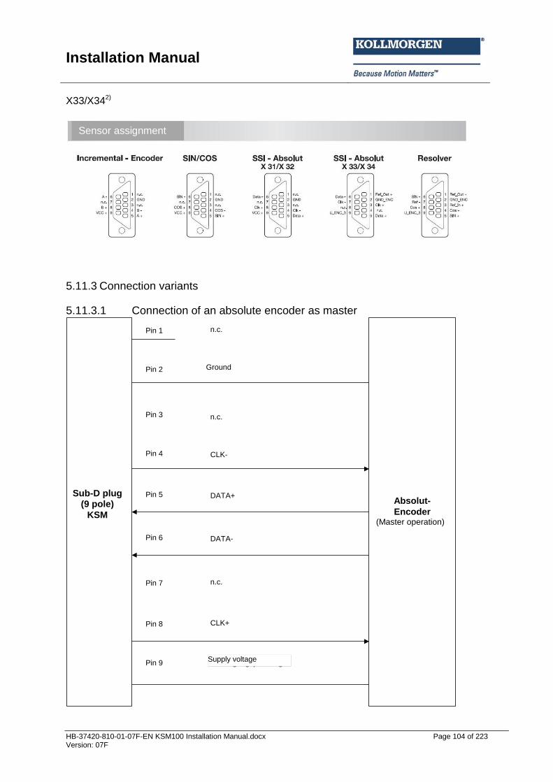
Installation Manual
HB-37420-810-01-07F-EN KSM100 Installation Manual.docx Page 104 of 223 Version: 07F
X33/X342)
5.11.3 Connection variants
5.11.3.1 Connection of an absolute encoder as master
Sub-D-
Stecker
(9 polig)
SMX
Absolut-
Encoder
(Master-Betrieb)
n.c.
n.c.
CLK-
DATA+
DATA-
n.c.
CLK+
Versorgungspannung
Pin 1
Pin 2
Pin 3
Pin 4
Pin 5
Pin 6
Pin 7
Pin 8
Pin 9
Ground
(Master operation)
Supply voltage
Sub-D plug (9 pole)
KSM
Sensor assignment
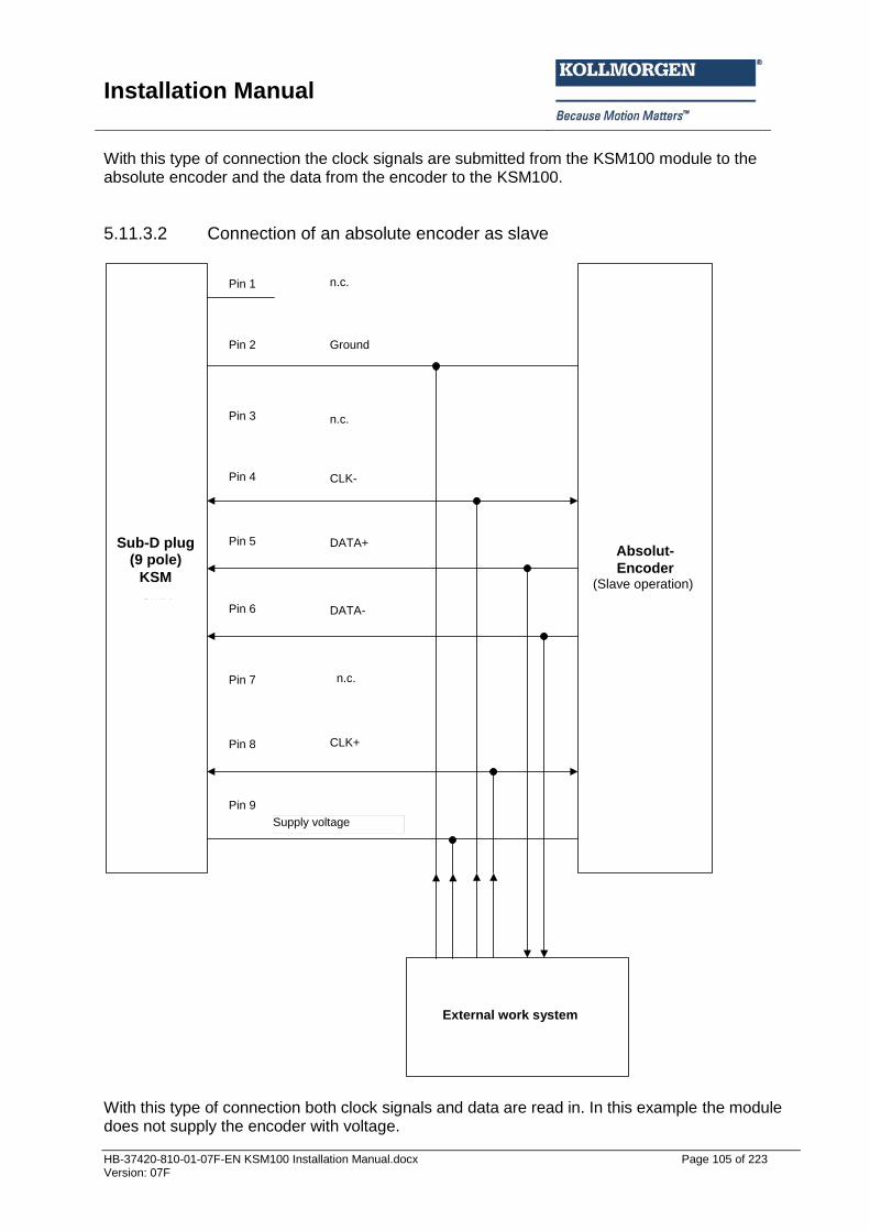
Installation Manual
HB-37420-810-01-07F-EN KSM100 Installation Manual.docx Page 105 of 223 Version: 07F
With this type of connection the clock signals are submitted from the KSM100 module to the absolute encoder and the data from the encoder to the KSM100.
5.11.3.2 Connection of an absolute encoder as slave
Sub-D-
Stecker
(9 polig)
SMX
Absolut-
Encoder
(Slave-Betrieb)
n.c.
Ground
n.c.
CLK-
DATA+
DATA-
n.c.
CLK+
Pin 1
Pin 2
Pin 3
Pin 4
Pin 5
Pin 6
Pin 7
Pin 8
Pin 9
externes Abtastsystem
Versorgungsspannung
With this type of connection both clock signals and data are read in. In this example the module does not supply the encoder with voltage.
(Slave operation)
External work system
Sub-D plug (9 pole)
KSM
Supply voltage

Installation Manual
HB-37420-810-01-07F-EN KSM100 Installation Manual.docx Page 106 of 223 Version: 07F
5.11.3.3 Connecting an incremental encoder with TTL-signal level
Pins 1, 3 and 7 stay open and are reserved for later expansions.
Sub-D-
Stecker
(9 polig)
SMX
Inkremental
Encoder
n.c.
Ground
n.c.
B-
A+
A-
n.c.
B+
Pin 1
Pin 2
Pin 3
Pin 4
Pin 5
Pin 6
Pin 7
Pin 8
Pin 9Versorgungsspannung
Sub-D plug (9 pole)
KSM
Supply voltage

Installation Manual
HB-37420-810-01-07F-EN KSM100 Installation Manual.docx Page 107 of 223 Version: 07F
5.11.3.4 Connection of a SIN/COS encoder
Sub-D-
Stecker
(9 polig)
SMX
SIN/COS
Geber
n.c.
Ground
n.c.
COS-
SIN+
SIN-
n.c.
COS+
Pin 1
Pin 2
Pin 3
Pin 4
Pin 5
Pin 6
Pin 7
Pin 8
Pin 9 Versorgungsspannung
Pins 1, 3 and 7 stay open and are reserved for later expansions.
SIN/COS
encoder
Supply voltage
Sub-D plug (9 pole)
KSM
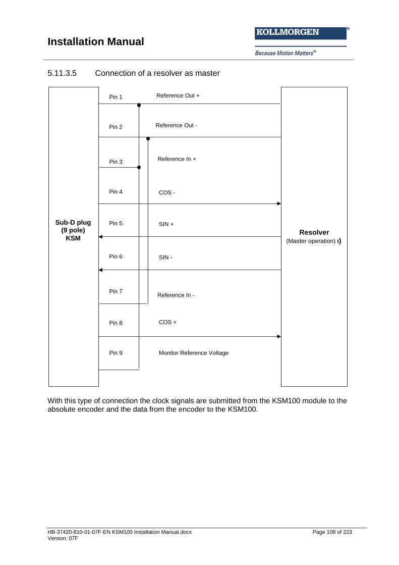
Installation Manual
HB-37420-810-01-07F-EN KSM100 Installation Manual.docx Page 108 of 223 Version: 07F
5.11.3.5 Connection of a resolver as master
Sub-D-
Stecker
(9 polig)
SMX
Resolver
(Master-Betrieb)
Reference Out +
COS -
SIN +
SIN -
COS +
Monitor Reference Voltage
Pin 1
Pin 2
Pin 3
Pin 4
Pin 5
Pin 6
Pin 7
Pin 8
Pin 9
Reference Out -
Reference In +
Reference In -
With this type of connection the clock signals are submitted from the KSM100 module to the absolute encoder and the data from the encoder to the KSM100.
(Master operation)
Sub-D plug (9 pole)
KSM
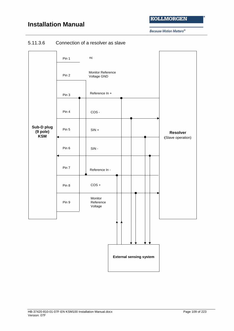
Installation Manual
HB-37420-810-01-07F-EN KSM100 Installation Manual.docx Page 109 of 223 Version: 07F
5.11.3.6 Connection of a resolver as slave
Sub-D-
Stecker
(9 polig)
SMX
Resolver
(Slave-Betrieb)
externes Abtastsystem
nc
COS -
SIN +
SIN -
COS +
Monitor
Reference
Voltage
Pin 1
Pin 2
Pin 3
Pin 4
Pin 5
Pin 6
Pin 7
Pin 8
Pin 9
Monitor Reference
Voltage GND
Reference In +
Reference In -
(Slave operation)
Sub-D plug (9 pole)
KSM
External sensing system

Installation Manual
HB-37420-810-01-07F-EN KSM100 Installation Manual.docx Page 110 of 223 Version: 07F
5.12 Configuration of measuring distances
5.12.1 General description of encoder configuration The most important input variables for the monitoring functions of the module are safe position, speed and acceleration. These are obtained by dual-channel generation from the connected sensor system. A category 4 compliant architecture, i.e. continuous dual-channel recording with high degree of diagnostic coverage, is required for Pl e acc. to EN 13849-1. For possible single-channel components (e.g. mechanical connection of the sensors/encoders with only one shaft/fastening) fault exclusions acc. to EN ISO 13849-2 may be used, if this should be necessary. For Pl d acc. to EN 13849-1 one may work with a reduced degree or diagnostic coverage. Simple design sensor systems (speed monitoring only) may under certain circumstances be sufficient under due consideration of the permissible fault exclusions acc. to EN ISO 13849-2. See also APPENDIX 1 Further configuration is described in the programming manual: 37420-820-01-xxF-KSM100 Programierhandbuch.pdf
5.12.2 Sensor type Absolute encoder and incremental measuring systems are possible, as well as counting pulse generating proximity switches
5.12.2.1 Absolute encoder: Data interface: Serial Synchronous Interface ( SSI ) with variable data length from 12 to 28 bit. Data format: Binary or Gray code, Physical Layer: RS-422 compatible SSI-Master operation: Clock rate: 150kHz SSI-Listener operation (slave mode): Max. external clock rate 200 KHz 1) or 350 kHz 2). Min. clock pause time 30 µsec Max. clock pause time 1 msec
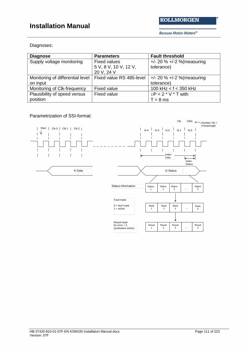
Installation Manual
HB-37420-810-01-07F-EN KSM100 Installation Manual.docx Page 111 of 223 Version: 07F
Diagnoses:
Diagnose Parameters Fault threshold
Supply voltage monitoring Fixed values 5 V, 8 V, 10 V, 12 V, 20 V, 24 V
+/- 20 % +/-2 %(measuring tolerance)
Monitoring of differential level on input
Fixed value RS 485-level +/- 20 % +/-2 %(measuring tolerance)
Monitoring of Clk-frequency Fixed value 100 kHz < f < 350 kHz
Plausibility of speed versus position
Fixed value DP < 2 * V * T with
T = 8 ms
Parametrization of SSI-format:
Anzahl Clk
= Framelength
K Daten O Status
Status information
Error Maske
0 = dont´t care 1 = aktiv
Ergebnis Maske
für Error = 0 (Auswertung aktiv)
Status
1
1Mask
2
Mask
3 ....Mask
0
Start Clk 0
Index
Daten
Index
Status
Mask
1
Clk 1 Clk 2N-4 N-3 N-2 N-1 N-0
Clk ClkN
Status
2
Status
0
Status
3 ....
Result
2
Result
3 ....Result
0
Result
1
K Data O Status
Index
Data
Index
Status
Number Clk =
Framelength
Status information
Fault mask 0 = don’t care
1 = active
Result mask for error = 0
(evaluation active)
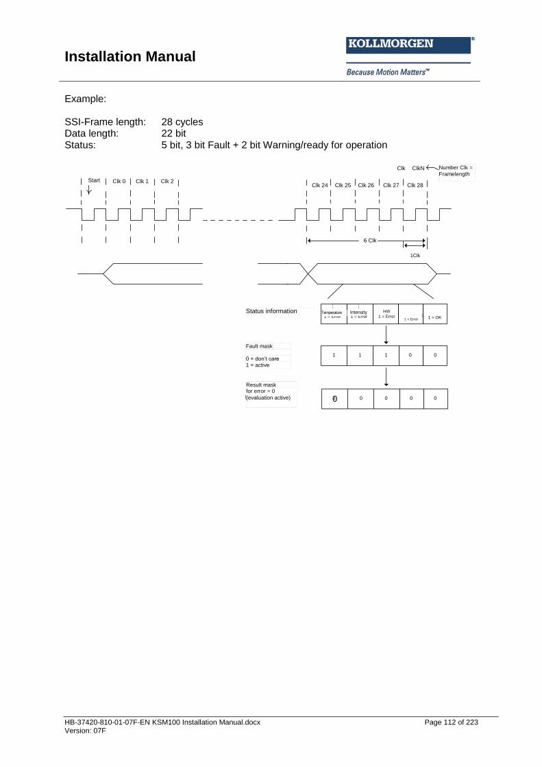
Installation Manual
HB-37420-810-01-07F-EN KSM100 Installation Manual.docx Page 112 of 223 Version: 07F
Example: SSI-Frame length: 28 cycles Data length: 22 bit Status: 5 bit, 3 bit Fault + 2 bit Warning/ready for operation
K Daten O Status
Status information
Error Maske
0 = dont´t care 1 = aktiv
Ergebnis Maske
für Error = False (Auswertung aktiv)
Temperatur
1 = Error
Intezität
1 = Error
HW
1 = Error
Warnung
Verschmutzung
1 = Error
Betriebsart
1 = OK
1 1 0 0
1 0 0 0 0
Start Clk 0
Clk ClkN
6 Clk
1Clk
Anzahl Clk
= Framelength
00
1
Clk 1 Clk 2Clk 24 Clk 25 Clk 26 Clk 27 Clk 28
Status information
Fault mask 0 = don’t care 1 = active
Result mask for error = 0
(evaluation active)
Temperature Intensity
Number Clk =
Framelength

Installation Manual
HB-37420-810-01-07F-EN KSM100 Installation Manual.docx Page 113 of 223 Version: 07F
5.12.2.2 Incremental encoder: Physical Layer: RS-422 compatible Measuring signal A/B. Track with 90 degree phase difference maximum frequency of input cycles 200 KHz 1) or 500 kHz 2) Diagnoses:
Diagnose Parameters Fault threshold
Supply voltage monitoring Fixed values 5 V, 8 V, 10 V, 12 V, 20 V, 24 V
+/- 20 % +/-2 %(measuring tolerance)
Monitoring of differential level on input
Fixed value RS 485-level +/- 20 % +/-2 %(measuring tolerance)
Monitoring of the counting signal separated for each track A/B
Fixed value DP > 4 increments
5.12.2.3 SinusCosinus encoder – standard mode Physical Layer: +/- 0.5 Vss (without voltage offset) Measuring signal A/B. Track with 90 degree phase difference Maximum frequency of input clock pulses. 200 KHz 1) or 500 kHz 2) Diagnoses:
Diagnose Parameters Fault threshold
Supply voltage monitoring Fixed values 5 V, 8 V, 10 V, 12 V, 20 V, 24 V
+/- 20 % +/-2 %(measuring tolerance)
Monitoring of amplitude SIN²+COS²
Fixed value 1VSS 65 % of 1 VSS +/- 2.5 %(measuring tolerance)
Monitoring of phases A/B Fixed value 90° +/- 30° +/-5° (measuring tolerance)
5.12.2.4 SinusCosinus encoder – high resolution mode:
Physical Layer: +/- 0.5 Vss (without voltage offset) Measuring signal A/B. Track with 90 degree phase difference Maximum frequency of input clock pulses. 15 kHz 2)
Diagnoses:
Diagnose Parameters Fault threshold
Supply voltage monitoring Fixed values 5 V, 8V, 10 V, 12 V, 20 V, 24 V
+/- 20 % +/-2 %(measuring tolerance)
Monitoring of amplitude SIN²+COS²
Fixed value 1VSS 65% of 1 VSS +/- 2.5%(measuring tolerance)
Monitoring of phases A/B Fixed value 90° +/- 30° +/-5° (measuring tolerance)
Monitoring of counting signal / signal phase quadrant
Fixed value +/- 45°

Installation Manual
HB-37420-810-01-07F-EN KSM100 Installation Manual.docx Page 114 of 223 Version: 07F
5.12.2.5 Proximity switch Signal level. 24 V/0 V Max. counting frequency. 10 kHz Circuit logic de-bounced Diagnoses:
Diagnose Parameters Fault threshold
Supply voltage monitoring Fixed values 5 V, 8 V, 10 V, 12 V, 20 V, 24V
+/- 20 % +/-2 %(measuring tolerance)
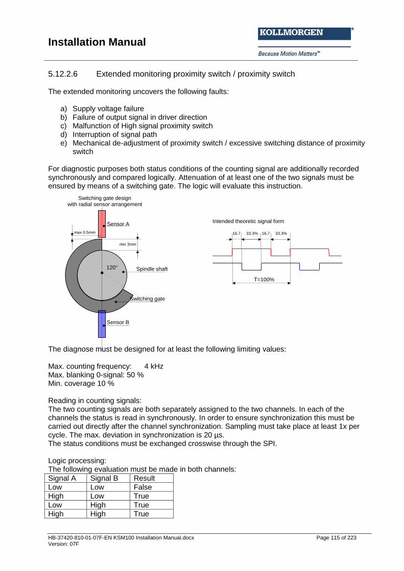
Installation Manual
HB-37420-810-01-07F-EN KSM100 Installation Manual.docx Page 115 of 223 Version: 07F
5.12.2.6 Extended monitoring proximity switch / proximity switch The extended monitoring uncovers the following faults:
a) Supply voltage failure b) Failure of output signal in driver direction c) Malfunction of High signal proximity switch d) Interruption of signal path e) Mechanical de-adjustment of proximity switch / excessive switching distance of proximity
switch For diagnostic purposes both status conditions of the counting signal are additionally recorded synchronously and compared logically. Attenuation of at least one of the two signals must be ensured by means of a switching gate. The logic will evaluate this instruction. The diagnose must be designed for at least the following limiting values: Max. counting frequency: 4 kHz Max. blanking 0-signal: 50 % Min. coverage 10 % Reading in counting signals: The two counting signals are both separately assigned to the two channels. In each of the channels the status is read in synchronously. In order to ensure synchronization this must be carried out directly after the channel synchronization. Sampling must take place at least 1x per cycle. The max. deviation in synchronization is 20 µs. The status conditions must be exchanged crosswise through the SPI. Logic processing: The following evaluation must be made in both channels:
Signal A Signal B Result
Low Low False
High Low True
Low High True
High High True
120°
Sensor A
Sensor B
min 3mm
max 0.5mm
T=100%
33.3%
16.7
33.3% 16.7
Intended theoretic signal form
Switching gate design with radial sensor arrangement
Spindle shaft
Switching gate
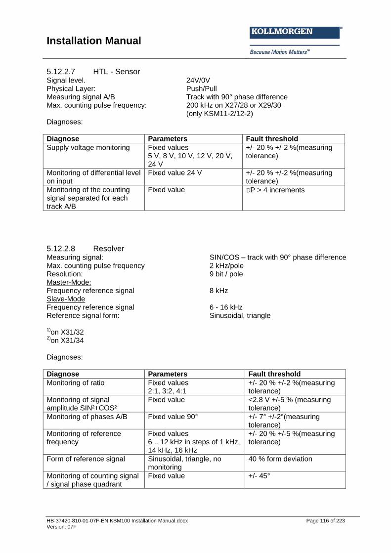
Installation Manual
HB-37420-810-01-07F-EN KSM100 Installation Manual.docx Page 116 of 223 Version: 07F
5.12.2.7 HTL - Sensor Signal level. 24V/0V Physical Layer: Push/Pull Measuring signal A/B Track with 90° phase difference Max. counting pulse frequency: 200 kHz on X27/28 or X29/30
(only KSM11-2/12-2) Diagnoses:
Diagnose Parameters Fault threshold
Supply voltage monitoring Fixed values 5 V, 8 V, 10 V, 12 V, 20 V, 24 V
+/- 20 % +/-2 %(measuring tolerance)
Monitoring of differential level on input
Fixed value 24 V +/- 20 % +/-2 %(measuring tolerance)
Monitoring of the counting signal separated for each track A/B
Fixed value DP > 4 increments
5.12.2.8 Resolver Measuring signal: SIN/COS – track with 90° phase difference Max. counting pulse frequency 2 kHz/pole Resolution: 9 bit / pole Master-Mode: Frequency reference signal 8 kHz Slave-Mode Frequency reference signal 6 - 16 kHz Reference signal form: Sinusoidal, triangle 1)on X31/32 2)on X31/34 Diagnoses:
Diagnose Parameters Fault threshold
Monitoring of ratio Fixed values 2:1, 3:2, 4:1
+/- 20 % +/-2 %(measuring tolerance)
Monitoring of signal amplitude SIN²+COS²
Fixed value <2.8 V +/-5 % (measuring tolerance)
Monitoring of phases A/B Fixed value 90° +/- 7° +/-2°(measuring tolerance)
Monitoring of reference frequency
Fixed values 6 .. 12 kHz in steps of 1 kHz, 14 kHz, 16 kHz
+/- 20 % +/-5 %(measuring tolerance)
Form of reference signal Sinusoidal, triangle, no monitoring
40 % form deviation
Monitoring of counting signal / signal phase quadrant
Fixed value +/- 45°

Installation Manual
HB-37420-810-01-07F-EN KSM100 Installation Manual.docx Page 117 of 223 Version: 07F
6 Response times of the KSM The response time is a very important safety related characteristic and must be strictly observed for each application / application related safety function. The following chapter lists the response times for individual functions, probably also in dependence on further parameters. If these data are insufficient for a specific application you should validate the actual time behaviour against the nominal behaviour by means of separate measurements. This applies also for the use of filter functions in particular.
Safety note:
The response times must be determined for each application related safety function in nominal behaviour and must then be compared with the actual value by using the following data.
Special care must be taken when using filter functions. Depending on the filter length / time the response time may be extended, which must be taken into account in the safety related design.
In case of particularly critical problem formulations the temporal behaviour must be validated by means of measurements.
During start-up of the device / alarm or fault reset the outputs may (depending on the application program) become active over the response time period. This must be taken into consideration when planning the safety function.
6.1 Response times in standard operation The cycle time of the KSM system serves as basis for calculating the response times. It is optionally available in 3 stages and is during operation T_cycle = 16 / 24 / 32 ms. The specified response times comply with the corresponding maximum running time for the actual application within the KSM100 module. Depending on the application, further, application dependent response times of the sensors and actuators used must be added, in order to obtain the total running time. Response times when using digital inputs and outputs on the basic group
Function Response time [ms] Explanation
Cycle time 16 24 32
Activation of a monitoring function by means of ENABLE with subsequent shut-down via digital output
16 *)
24 *)
32 *)
Activation of a monitoring function by means of the ENABLE signal.
Activation of a monitoring function by means of ENABLE with subsequent shut-down via safety relay
39 *)
47 *)
55 *)
Activation of a monitoring function by means of the ENABLE signal.
Response of an already activated monitoring function including PLC editing in case of position and speed processing via digital output
36 *)
56 *)
70 *)
With a monitoring function that has already been activated via ENABLE, the module requires one cycle to calculate the current speed value. During the next cycle after calculation of the monitoring function the information is further processed and output by the PLC, i.e. according to the implemented logic this will lead to e.g. switching of an output.
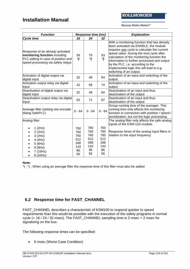
Installation Manual
HB-37420-810-01-07F-EN KSM100 Installation Manual.docx Page 118 of 223 Version: 07F
Function Response time [ms] Explanation
Cycle time 16 24 32
Response of an already activated monitoring function including PLC editing in case of position and speed processing via safety relays
59 *)
79 *)
93 *)
With a monitoring function that has already been activated via ENABLE, the module requires one cycle to calculate the current speed value. During the next cycle after calculation of the monitoring function the information is further processed and output by the PLC, i.e. according to the implemented logic this will lead to e.g. switching of an output.
Activation of digital output via digital input
32 48 64 Activation of an input and switching of the output
Activation output relay via digital input
42 58 74 Activation of an input and switching of the output
Deactivation of digital output via digital input
32 48 64 Deactivation of an input and thus deactivation of the output
Deactivation output relay via digital input
55 71 87 Deactivation of an input and thus deactivation of the output
Average filter (setting see encoder dialog SafePLC)
0 - 64 0 - 64 0 - 64
Group running time of the averager. This running time only effects the monitoring function in connection with position / speed / acceleration, but not the logic processing.
Analog filter
1 (2Hz)
2 (2Hz)
3 (2Hz)
4 (4Hz)
5 (6Hz)
6 (8Hz)
7 (10Hz)
8 (20Hz)
760 760 760 512 268 143 86 56
760 760 760 512 268 143 86 56
760 760 760 512 268 143 86 56
The analog filter only affects the safe analog inputs of the KSM-12A module. Response times of the analog input filters in relation to the input frequency
Note: *) : *) : When using an average filter the response time of this filter must also be added
6.2 Response time for FAST_CHANNEL
FAST_CHANNEL describes a characteristic of KSM100 to respond quicker to speed requirements than this would be possible with the execution of the safety programs in normal cycle (= 16 / 24 / 32 msec). The FAST_CHANNEL sampling time is 2 msec + 2 msec for signalizing on the bus.
The following response times can be specified:
6 msec (Worst Case Condition)
Installation Manual
HB-37420-810-01-07F-EN KSM100 Installation Manual.docx Page 119 of 223 Version: 07F
Safety note:
When using FAST_CHANNEL you should bear in mind that shutting down within the time specified above for a given speed threshold is only possible, if the sensor information has a sufficient resolution. The smallest resolvable switching threshold of the FAST_CHANNEL requires at least 2 edge changes on the corresponding sensor system within a period of 2 msec.
This function can only be used in connection with semi-conductor outputs.
6.3 Response times for fault distance monitoring The following calculation schematic applies for calculating the Worst Case Scenario. System speed to the sampling instant V(t) System speed in case of KSM response: VA(tMonitoring threshold (SLS or SCA): VS = constant for all t Parameterized filter value: XF = constant for all t Maximum possible acceleration of the application: a = constant for all t Deceleration after shut-down: aV = constant for all t Sampling instant for occurrence of a Worst Case event: TFault Response time of the KSM-system: tResponse For the Worst Case assessment it is assumed that the drive will initially move exactly to the parameterized threshold v0 with a speed v(k) and then will accelerate to the maximum possible value a0.
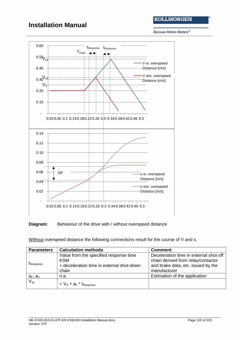
Installation Manual
HB-37420-810-01-07F-EN KSM100 Installation Manual.docx Page 120 of 223 Version: 07F
Diagram: Behaviour of the drive with / without overspeed distance Without overspeed distance the following connections result for the course of V and s.
Parameters Calculation methods Comment
tResponse
Value from the specified response time KSM + deceleration time in external shut-down chain
Deceleration time in external shut-off chain derived from relay/contactor and brake data, etc. issued by the manufacturer
aF, aV n.a. Estimation of the application
Va1
= VS + aF * tResponse
-
0.10
0.20
0.30
0.40
0.50
0.60
0.02 0.06 0.1 0.14 0.18 0.22 0.26 0.3 0.34 0.38 0.42 0.46 0.5
V m. OverspeedDistanz [m/s]
V ohne OverspeedDistanz [m/s]
-
0.02
0.04
0.06
0.08
0.10
0.12
0.14
0.02 0.06 0.1 0.14 0.18 0.22 0.26 0.3 0.34 0.38 0.42 0.46 0.5
s m. OverspeedDistanz [m]
s ohne OverspeedDistanz[m]
VS
Va1
TFault
tResponse
Va2
tResponse
XF
Distance [m/s]
Distance [m/s]
Distance [m/s]
Distance [m/s]
V w. overspeed
V w/o. overspeed
s w. overspeed
s w/o. overspeed
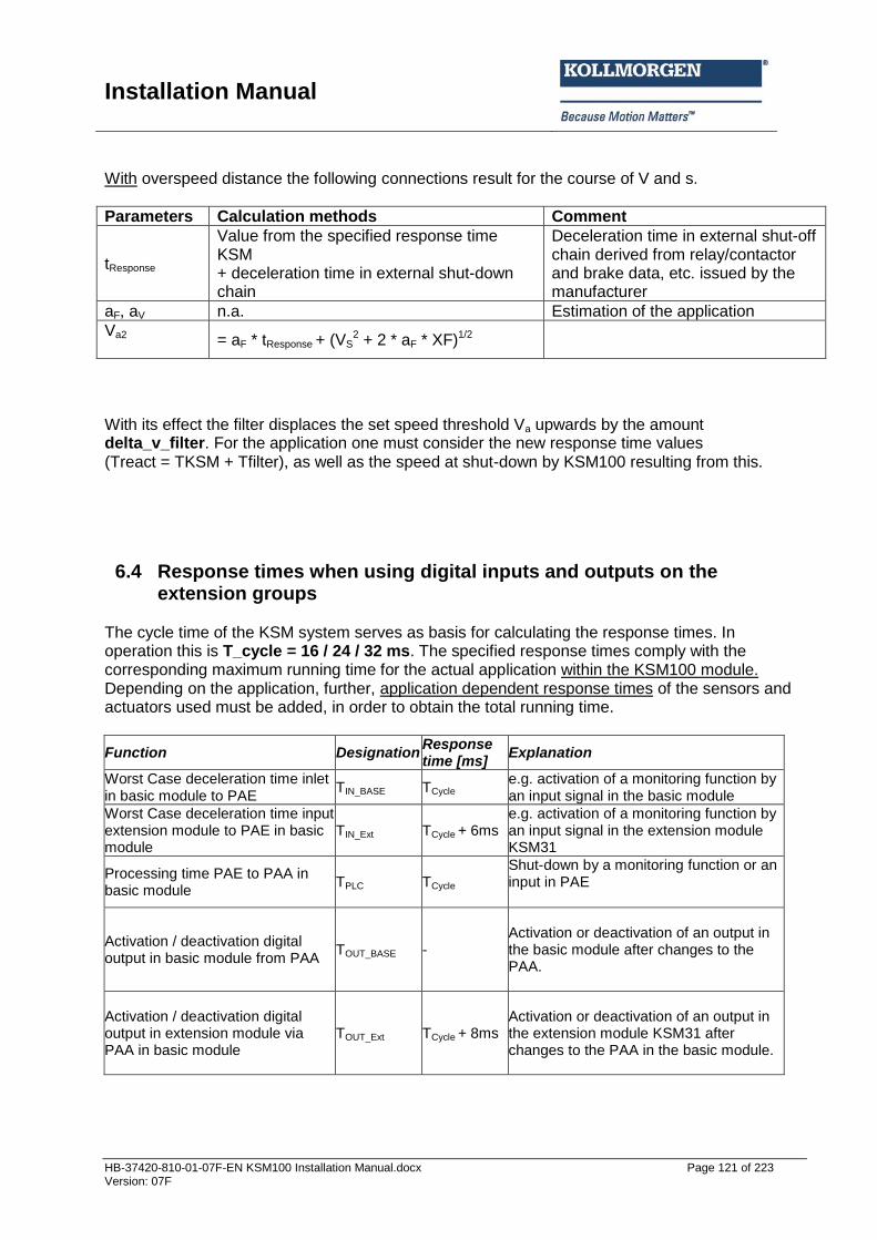
Installation Manual
HB-37420-810-01-07F-EN KSM100 Installation Manual.docx Page 121 of 223 Version: 07F
With overspeed distance the following connections result for the course of V and s.
Parameters Calculation methods Comment
tResponse
Value from the specified response time KSM + deceleration time in external shut-down chain
Deceleration time in external shut-off chain derived from relay/contactor and brake data, etc. issued by the manufacturer
aF, aV n.a. Estimation of the application
Va2
= aF * tResponse + (VS2 + 2 * aF * XF)1/2
With its effect the filter displaces the set speed threshold Va upwards by the amount delta_v_filter. For the application one must consider the new response time values (Treact = TKSM + Tfilter), as well as the speed at shut-down by KSM100 resulting from this.
6.4 Response times when using digital inputs and outputs on the extension groups
The cycle time of the KSM system serves as basis for calculating the response times. In operation this is T_cycle = 16 / 24 / 32 ms. The specified response times comply with the corresponding maximum running time for the actual application within the KSM100 module. Depending on the application, further, application dependent response times of the sensors and actuators used must be added, in order to obtain the total running time.
Function Designation Response time [ms]
Explanation
Worst Case deceleration time inlet in basic module to PAE
TIN_BASE TCycle e.g. activation of a monitoring function by an input signal in the basic module
Worst Case deceleration time input extension module to PAE in basic module
TIN_Ext TCycle + 6ms e.g. activation of a monitoring function by an input signal in the extension module KSM31
Processing time PAE to PAA in basic module
TPLC TCycle Shut-down by a monitoring function or an input in PAE
Activation / deactivation digital output in basic module from PAA
TOUT_BASE - Activation or deactivation of an output in the basic module after changes to the PAA.
Activation / deactivation digital output in extension module via PAA in basic module
TOUT_Ext TCycle + 8ms Activation or deactivation of an output in the extension module KSM31 after changes to the PAA in the basic module.
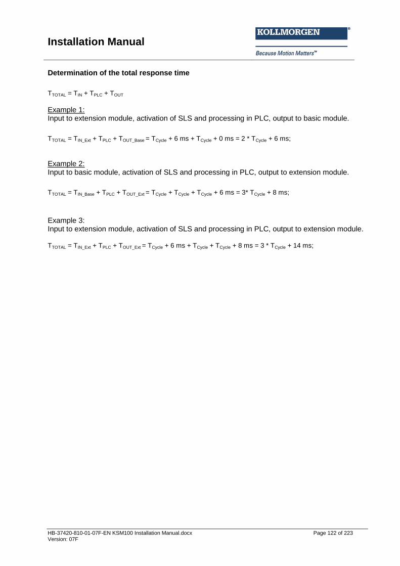
Installation Manual
HB-37420-810-01-07F-EN KSM100 Installation Manual.docx Page 122 of 223 Version: 07F
Determination of the total response time
TTOTAL = TIN + TPLC + TOUT
Example 1: Input to extension module, activation of SLS and processing in PLC, output to basic module.
TTOTAL = TIN_Ext + TPLC + TOUT_Base = TCycle + 6 ms + TCycle + 0 ms = 2 * TCycle + 6 ms;
Example 2: Input to basic module, activation of SLS and processing in PLC, output to extension module.
TTOTAL = TIN_Base + TPLC + TOUT_Ext = TCycle + TCycle + TCycle + 6 ms = 3* TCycle + 8 ms;
Example 3: Input to extension module, activation of SLS and processing in PLC, output to extension module. TTOTAL = TIN_Ext + TPLC + TOUT_Ext = TCycle + 6 ms + TCycle + TCycle + 8 ms = 3 * TCycle + 14 ms;
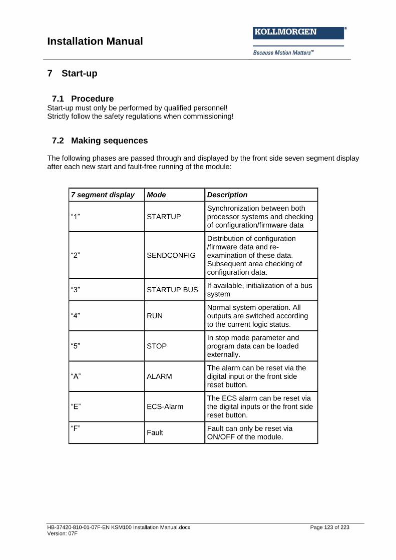
Installation Manual
HB-37420-810-01-07F-EN KSM100 Installation Manual.docx Page 123 of 223 Version: 07F
7 Start-up
7.1 Procedure Start-up must only be performed by qualified personnel! Strictly follow the safety regulations when commissioning!
7.2 Making sequences The following phases are passed through and displayed by the front side seven segment display after each new start and fault-free running of the module:
7 segment display Mode Description
“1” STARTUP Synchronization between both processor systems and checking of configuration/firmware data
“2” SENDCONFIG
Distribution of configuration /firmware data and re-examination of these data. Subsequent area checking of configuration data.
“3” STARTUP BUS If available, initialization of a bus system
“4” RUN Normal system operation. All outputs are switched according to the current logic status.
“5” STOP In stop mode parameter and program data can be loaded externally.
“A” ALARM The alarm can be reset via the digital input or the front side reset button.
“E” ECS-Alarm The ECS alarm can be reset via the digital inputs or the front side reset button.
“F”
Fault Fault can only be reset via ON/OFF of the module.
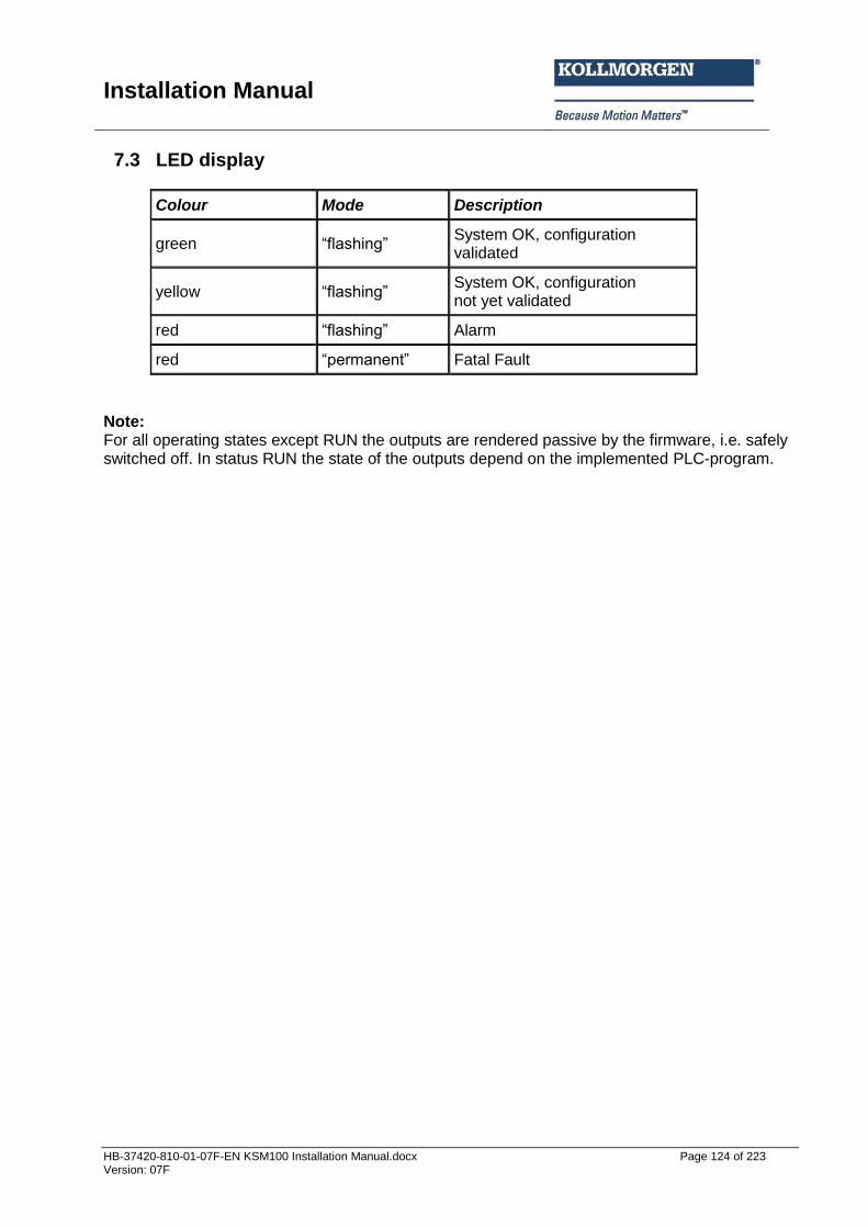
Installation Manual
HB-37420-810-01-07F-EN KSM100 Installation Manual.docx Page 124 of 223 Version: 07F
7.3 LED display
Colour Mode Description
green “flashing” System OK, configuration validated
yellow “flashing” System OK, configuration not yet validated
red “flashing” Alarm
red “permanent” Fatal Fault
Note: For all operating states except RUN the outputs are rendered passive by the firmware, i.e. safely switched off. In status RUN the state of the outputs depend on the implemented PLC-program.
Installation Manual
HB-37420-810-01-07F-EN KSM100 Installation Manual.docx Page 125 of 223 Version: 07F
7.4 Parameterization Parameterization takes place via the program SafePLC KSM100. The transmission of these data to the module requires a programming adapter, the drivers of which must first be installed by the user. Parameterization is described in the KSM100 programming manual.
7.5 Function test As a measure to ensure the safety of the module, the reliability of all safety functions must be checked once every year. For this purpose the modules used in the parameterization (inputs, outputs, monitoring functions and logic modules) must be checked with respect to function or shut-down. See programming manual.
7.6 Validation In order to assure the reliability of the implemented safety functions the user must check and document the parameters and links after the start-up and parameterization has taken place. This is supported by a validation assistant in the programming desktop (see chapter “Safet related examination”).

Installation Manual
HB-37420-810-01-07F-EN KSM100 Installation Manual.docx Page 126 of 223 Version: 07F
8 Safety related examination In order to assure the reliability of the implemented safety functions the user must check and document the parameters and links after the start-up and parameterization has taken place. This is supported by the parameterization software SafePLC KSM100 (see programming manual). On the first page one can enter general system data. The last page of the validation report contains individual evidence concerning the safety related examination.
Here the following entries are mandatory: • Serial number (identical ith the serial number on the t pe plate) • Identit of the module Here the responsible tester of the safety module confirms that the CRC's displayed in the programming desktop are identical with the CRC stored in the KSM100 module. Once all header data have been entered, the validation report can be generated by pressing the control button “Save”. The parameterization tool then creates a text file (.TXT) with the file name of the program data set. The text file contains the following information:
The 3 pages of header data edited above
The configuration of the encoder
The parameters of the existing monitoring function
The PLC program as instruction list After the transmission of the configuration and program data to the KSM100 module the status LED flashes yellow. This indicates that the configuration data have not yet been validated. Pressing the button “LOCK CONFIGURATION” at the end of the validation dialog highlights the data as “Validated” and the LED flashes in green.
Installation Manual
HB-37420-810-01-07F-EN KSM100 Installation Manual.docx Page 127 of 223 Version: 07F
9 Maintenance
9.1 Modification / handling changes to the device Maintenance work must solely be carried out by qualified personnel. Regular maintenance work is not required. Repair The devices must always be replaced as whole units Repair work on the device can only be performed in the factory. Warranty By opening the module without permission the warranty will become null and void. Note: By modifying the module the safety approval will become null and void!
9.2 Exchanging a module The following should be noted when exchanging a module: Disconnect the electric power converter from the main supply. Switch off the electric power supply for the device and disconnect. Pull off the encoder plug. Disconnect any other pluggable connections. Take the module off the top hat rail and pack up EMC-compliant. Mount the new module on the top hat rail. Reconnect all connections. Switch on the electric power converter. Switch on the supply voltage. Configure the device Note: Pluggable connections of the KSM100 module must generally not be disconnected or connected in live condition. There is a danger of sensor damage, particularly with connected position or speed sensors.
9.3 Maintenance intervals
Module replacement See technical data
Function test See chapter “Start-up”

Installation Manual
HB-37420-810-01-07F-EN KSM100 Installation Manual.docx Page 128 of 223 Version: 07F
10 Technical data
10.1 Environmental conditions Class of protection IP 52 Ambient temperature 0°C* ... 50°C Climatic category 3 acc. to DIN 50 178 Lifetime 90000h at 50°C ambient
10.2 Safety related characteristic data
Max. obtainable safety class SIL 3 acc. to EN61508 Category 4 acc. to EN945-1 Performance-Level e acc. To EN ISO 13849-1
System structure 2-channel with diagnose (1002)
Rating of operating mode “high demand” acc. to EN 61508 (high demand rate)
Probability of an endangering failure per hour (PFH-value)
KSM100 < 1.4 E-8 (14FIT)
Proof-Test-Interval (EN61508) 20 years, after this time the module must be replaced
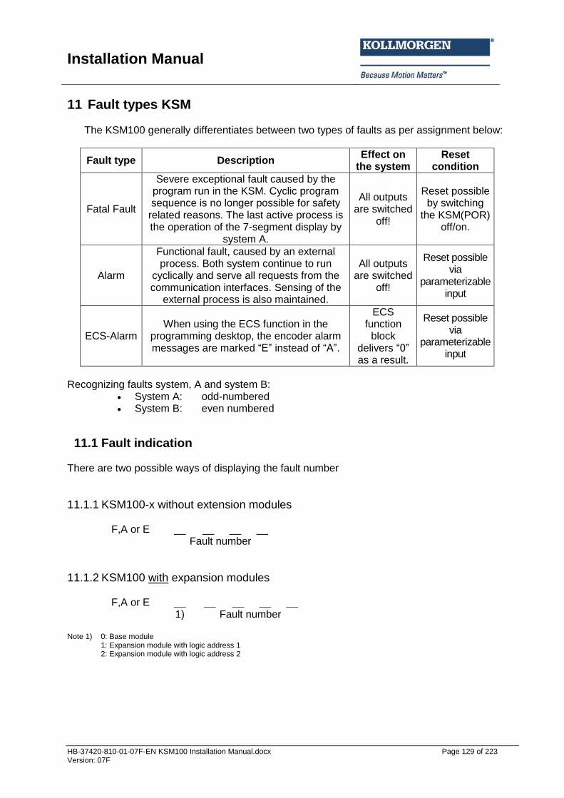
Installation Manual
HB-37420-810-01-07F-EN KSM100 Installation Manual.docx Page 129 of 223 Version: 07F
11 Fault types KSM
The KSM100 generally differentiates between two types of faults as per assignment below:
Fault type Description Effect on
the system Reset
condition
Fatal Fault
Severe exceptional fault caused by the program run in the KSM. Cyclic program sequence is no longer possible for safety
related reasons. The last active process is the operation of the 7-segment display by
system A.
All outputs are switched
off!
Reset possible by switching
the KSM(POR) off/on.
Alarm
Functional fault, caused by an external process. Both system continue to run
cyclically and serve all requests from the communication interfaces. Sensing of the
external process is also maintained.
All outputs are switched
off!
Reset possible via
parameterizable input
ECS-Alarm When using the ECS function in the
programming desktop, the encoder alarm messages are marked “E” instead of “A”.
ECS function
block delivers “0” as a result.
Reset possible via
parameterizable input
Recognizing faults system, A and system B:
System A: odd-numbered System B: even numbered
11.1 Fault indication There are two possible ways of displaying the fault number
11.1.1 KSM100-x without extension modules
F,A or E __ __ __ __ Fault number
11.1.2 KSM100 with expansion modules
F,A or E __ __ __ __ __ 1) Fault number
Note 1) 0: Base module 1: Expansion module with logic address 1 2: Expansion module with logic address 2
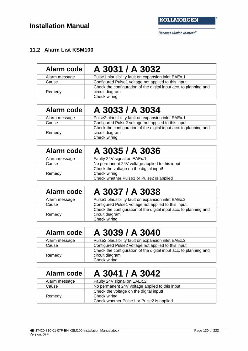
Installation Manual
HB-37420-810-01-07F-EN KSM100 Installation Manual.docx Page 130 of 223 Version: 07F
11.2 Alarm List KSM100
Alarm code A 3031 / A 3032 Alarm message Pulse1 plausibility fault on expansion inlet EAEx.1
Cause Configured Pulse1 voltage not applied to this input.
Remedy Check the configuration of the digital input acc. to planning and circuit diagram Check wiring
Alarm code A 3033 / A 3034 Alarm message Pulse2 plausibility fault on expansion inlet EAEx.1
Cause Configured Pulse2 voltage not applied to this input.
Remedy Check the configuration of the digital input acc. to planning and circuit diagram Check wiring
Alarm code A 3035 / A 3036 Alarm message Faulty 24V signal on EAEx.1
Cause No permanent 24V voltage applied to this input
Remedy Check the voltage on the digital input! Check wiring Check whether Pulse1 or Pulse2 is applied
Alarm code A 3037 / A 3038 Alarm message Pulse1 plausibility fault on expansion inlet EAEx.2
Cause Configured Pulse1 voltage not applied to this input.
Remedy Check the configuration of the digital input acc. to planning and circuit diagram Check wiring
Alarm code A 3039 / A 3040 Alarm message Pulse2 plausibility fault on expansion inlet EAEx.2
Cause Configured Pulse2 voltage not applied to this input.
Remedy Check the configuration of the digital input acc. to planning and circuit diagram Check wiring
Alarm code A 3041 / A 3042 Alarm message Faulty 24V signal on EAEx.2
Cause No permanent 24V voltage applied to this input
Remedy Check the voltage on the digital input! Check wiring Check whether Pulse1 or Pulse2 is applied
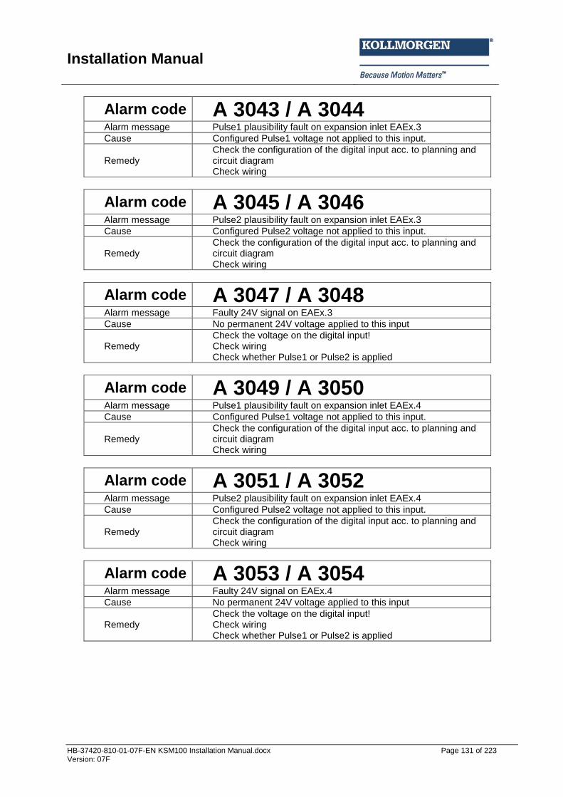
Installation Manual
HB-37420-810-01-07F-EN KSM100 Installation Manual.docx Page 131 of 223 Version: 07F
Alarm code A 3043 / A 3044 Alarm message Pulse1 plausibility fault on expansion inlet EAEx.3
Cause Configured Pulse1 voltage not applied to this input.
Remedy Check the configuration of the digital input acc. to planning and circuit diagram Check wiring
Alarm code A 3045 / A 3046 Alarm message Pulse2 plausibility fault on expansion inlet EAEx.3
Cause Configured Pulse2 voltage not applied to this input.
Remedy Check the configuration of the digital input acc. to planning and circuit diagram Check wiring
Alarm code A 3047 / A 3048 Alarm message Faulty 24V signal on EAEx.3
Cause No permanent 24V voltage applied to this input
Remedy Check the voltage on the digital input! Check wiring Check whether Pulse1 or Pulse2 is applied
Alarm code A 3049 / A 3050 Alarm message Pulse1 plausibility fault on expansion inlet EAEx.4
Cause Configured Pulse1 voltage not applied to this input.
Remedy Check the configuration of the digital input acc. to planning and circuit diagram Check wiring
Alarm code A 3051 / A 3052 Alarm message Pulse2 plausibility fault on expansion inlet EAEx.4
Cause Configured Pulse2 voltage not applied to this input.
Remedy Check the configuration of the digital input acc. to planning and circuit diagram Check wiring
Alarm code A 3053 / A 3054 Alarm message Faulty 24V signal on EAEx.4
Cause No permanent 24V voltage applied to this input
Remedy Check the voltage on the digital input! Check wiring Check whether Pulse1 or Pulse2 is applied

Installation Manual
HB-37420-810-01-07F-EN KSM100 Installation Manual.docx Page 132 of 223 Version: 07F
Alarm code A 3055 / A 3056 Alarm message Pulse1 plausibility fault on expansion inlet EAEx.5
Cause Configured Pulse1 voltage not applied to this input.
Remedy Check the configuration of the digital input acc. to planning and circuit diagram Check wiring
Alarm code A 3057 / A 3058 Alarm message Pulse2 plausibility fault on expansion inlet EAEx.5
Cause Configured Pulse2 voltage not applied to this input.
Remedy Check the configuration of the digital input acc. to planning and circuit diagram Check wiring
Alarm code A 3059 / A 3060 Alarm message Faulty 24V signal on EAEx.5
Cause No permanent 24V voltage applied to this input
Remedy Check the voltage on the digital input! Check wiring Check whether Pulse1 or Pulse2 is applied
Alarm code A 3061 / A 3062 Alarm message Pulse1 plausibility fault on expansion inlet EAEx.6
Cause Configured Pulse1 voltage not applied to this input.
Remedy Check the configuration of the digital input acc. to planning and circuit diagram Check wiring
Alarm code A 3063 / A 3064 Alarm message Pulse2 plausibility fault on expansion inlet EAEx.6
Cause Configured Pulse2 voltage not applied to this input.
Remedy Check the configuration of the digital input acc. to planning and circuit diagram Check wiring
Alarm code A 3065 / A 3066 Alarm message Pulse1 plausibility fault on expansion inlet EAEx.7
Cause Configured Pulse1 voltage not applied to this input.
Remedy Check the configuration of the digital input acc. to planning and circuit diagram Check wiring
Alarm code A 3067 / A 3068 Alarm message Pulse1 plausibility fault on expansion inlet EAEx.7
Cause Configured Pulse1 voltage not applied to this input.
Remedy Check the configuration of the digital input acc. to planning and circuit diagram Check wiring
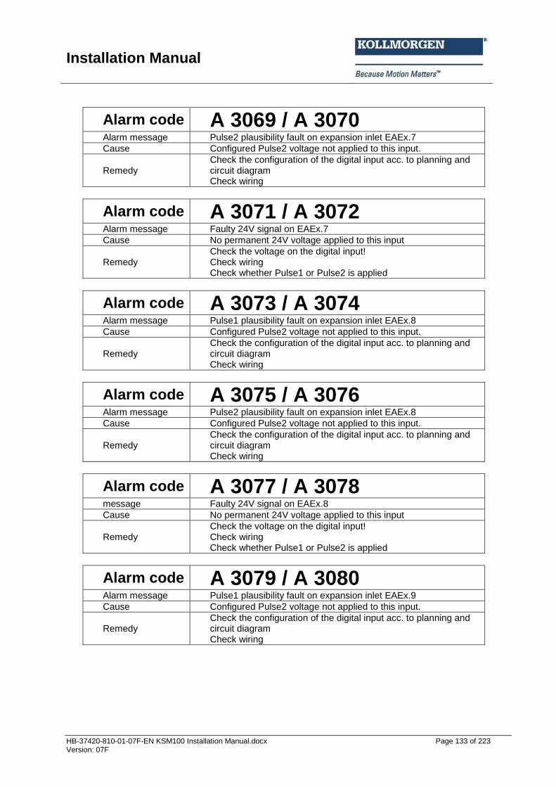
Installation Manual
HB-37420-810-01-07F-EN KSM100 Installation Manual.docx Page 133 of 223 Version: 07F
Alarm code A 3069 / A 3070 Alarm message Pulse2 plausibility fault on expansion inlet EAEx.7
Cause Configured Pulse2 voltage not applied to this input.
Remedy Check the configuration of the digital input acc. to planning and circuit diagram Check wiring
Alarm code A 3071 / A 3072 Alarm message Faulty 24V signal on EAEx.7
Cause No permanent 24V voltage applied to this input
Remedy Check the voltage on the digital input! Check wiring Check whether Pulse1 or Pulse2 is applied
Alarm code A 3073 / A 3074 Alarm message Pulse1 plausibility fault on expansion inlet EAEx.8
Cause Configured Pulse2 voltage not applied to this input.
Remedy Check the configuration of the digital input acc. to planning and circuit diagram Check wiring
Alarm code A 3075 / A 3076 Alarm message Pulse2 plausibility fault on expansion inlet EAEx.8
Cause Configured Pulse2 voltage not applied to this input.
Remedy Check the configuration of the digital input acc. to planning and circuit diagram Check wiring
Alarm code A 3077 / A 3078 message Faulty 24V signal on EAEx.8
Cause No permanent 24V voltage applied to this input
Remedy Check the voltage on the digital input! Check wiring Check whether Pulse1 or Pulse2 is applied
Alarm code A 3079 / A 3080 Alarm message Pulse1 plausibility fault on expansion inlet EAEx.9
Cause Configured Pulse2 voltage not applied to this input.
Remedy Check the configuration of the digital input acc. to planning and circuit diagram Check wiring

Installation Manual
HB-37420-810-01-07F-EN KSM100 Installation Manual.docx Page 134 of 223 Version: 07F
Alarm code A 3081 / A 3082 Alarm message Pulse2 plausibility fault on expansion inlet EAEx.9
Cause Configured Pulse2 voltage not applied to this input.
Remedy Check the configuration of the digital input acc. to planning and circuit diagram Check wiring
Alarm code A 3083 / A 3084 Alarm message Faulty 24V signal on EAEx.9
Cause No permanent 24V voltage applied to this input
Remedy Check the voltage on the digital input! Check wiring Check whether Pulse1 or Pulse2 is applied
Alarm code A 3085 / A 3086 Alarm message Pulse1 plausibility fault on expansion inlet EAEx.10
Cause Configured Pulse2 voltage not applied to this input.
Remedy Check the configuration of the digital input acc. to planning and circuit diagram Check wiring
Alarm code A 3087 / A 3088 Alarm message Pulse2 plausibility fault on expansion inlet EAEx.10
Cause Configured Pulse2 voltage not applied to this input.
Remedy Check the configuration of the digital input acc. to planning and circuit diagram Check wiring
Alarm code A 3089 / A 3090 Alarm message Faulty 24V signal on EAEx.10
Cause No permanent 24V voltage applied to this input
Remedy Check the voltage on the digital input! Check wiring Check whether Pulse1 or Pulse2 is applied
Alarm code A 3101 / A 3102 Alarm message Pulse1 plausibility fault on input DI1
Cause Configured Pulse1 voltage not applied to this input.
Remedy Check the configuration of the digital input acc. to planning and circuit diagram Check wiring
Alarm code A 3103 / A 3104 Alarm message Pulse1 plausibility fault on input DI2
Cause Configured Pulse1 voltage not applied to this input.
Remedy Check the configuration of the digital input acc. to planning and circuit diagram Check wiring

Installation Manual
HB-37420-810-01-07F-EN KSM100 Installation Manual.docx Page 135 of 223 Version: 07F
Alarm code A 3105 / A 3106 Alarm message Pulse1 plausibility fault on input DI3
Cause Configured Pulse1 voltage not applied to this input.
Remedy Check the configuration of the digital input acc. to planning and circuit diagram Check wiring
Alarm code A 3107 / A 3108 Alarm message Pulse1 plausibility fault on input DI4
Cause Configured Pulse1 voltage not applied to this input.
Remedy Check the configuration of the digital input acc. to planning and circuit diagram Check wiring
Alarm code A 3109 / A 3110 Alarm message Pulse1 plausibility fault on input DI5
Cause Configured Pulse1 voltage not applied to this input.
Remedy Check the configuration of the digital input acc. to planning and circuit diagram Check wiring
Alarm code A 3111 / A 3112 Alarm message Pulse1 plausibility fault on input DI6
Cause Configured Pulse1 voltage not applied to this input.
Remedy Check the configuration of the digital input acc. to planning and circuit diagram Check wiring
Alarm code A 3113 / A 3114 Alarm message Pulse1 plausibility fault on input DI7
Cause Configured Pulse1 voltage not applied to this input.
Remedy Check the configuration of the digital input acc. to planning and circuit diagram Check wiring
Alarm code A 3115 / A 3116 Alarm message Pulse1 plausibility fault on input DI8
Cause Configured Pulse1 voltage not applied to this input.
Remedy Check the configuration of the digital input acc. to planning and circuit diagram Check wiring

Installation Manual
HB-37420-810-01-07F-EN KSM100 Installation Manual.docx Page 136 of 223 Version: 07F
Alarm code A 3117 / A 3118 Alarm message Pulse2 plausibility fault on input DI1
Cause No Pulse2 voltage applied to this input
Remedy Check the configuration of the digital input acc. to planning and circuit diagram Check wiring
Alarm code A 3119 / A 3120 Alarm message Pulse2 plausibility fault on input DI2
Cause No Pulse2 voltage applied to this input
Remedy Check the configuration of the digital input acc. to planning and circuit diagram Check wiring
Alarm code A 3121 / A 3122 Alarm message Pulse2 plausibility fault on input DI3
Cause No Pulse2 voltage applied to this input
Remedy Check the configuration of the digital input acc. to planning and circuit diagram Check wiring
Alarm code A 3123 / A 3124 Alarm message Pulse2 plausibility fault on input DI4
Cause No Pulse2 voltage applied to this input
Remedy Check the configuration of the digital input acc. to planning and circuit diagram Check wiring
Alarm code A 3125 / A 3126 Alarm message Pulse2 plausibility fault on input DI5
Cause No Pulse2 voltage applied to this input
Remedy Check the configuration of the digital input acc. to planning and circuit diagram Check wiring
Alarm code A 3127 / A 3128 Alarm message Pulse2 plausibility fault on input DI6
Cause No Pulse2 voltage applied to this input
Remedy Check the configuration of the digital input acc. to planning and circuit diagram Check wiring
Alarm code A 3129 / A 3130 Alarm message Pulse2 plausibility fault on input DI7
Cause No Pulse2 voltage applied to this input
Remedy Check the configuration of the digital input acc. to planning and circuit diagram Check wiring

Installation Manual
HB-37420-810-01-07F-EN KSM100 Installation Manual.docx Page 137 of 223 Version: 07F
Alarm code A 3131 / A 3132 Alarm message Pulse2 plausibility fault on input DI8
Cause No Pulse2 voltage applied to this input
Remedy Check the configuration of the digital input acc. to planning and circuit diagram Check wiring
Alarm code A 3133 / A 3134 Alarm message Pulse1 plausibility fault on input DI9
Cause Configured Pulse1 voltage not applied to this input.
Remedy Check the configuration of the digital input acc. to planning and circuit diagram Check wiring
Alarm code A 3135 / A 3136 Alarm message Pulse1 plausibility fault on input DI10
Cause Configured Pulse1 voltage not applied to this input.
Remedy Check the configuration of the digital input acc. to planning and circuit diagram Check wiring
Alarm code A 3137 / A 3138 Alarm message Pulse1 plausibility fault on input DI11
Cause Configured Pulse1 voltage not applied to this input.
Remedy Check the configuration of the digital input acc. to planning and circuit diagram Check wiring
Alarm code A 3139 / A 3140 Alarm message Pulse1 plausibility fault on input DI12
Cause Configured Pulse1 voltage not applied to this input.
Remedy Check the configuration of the digital input acc. to planning and circuit diagram Check wiring
Alarm code A 3141 / A 3142 Alarm message Pulse1 plausibility fault on input DI13
Cause Configured Pulse1 voltage not applied to this input.
Remedy Check the configuration of the digital input acc. to planning and circuit diagram Check wiring

Installation Manual
HB-37420-810-01-07F-EN KSM100 Installation Manual.docx Page 138 of 223 Version: 07F
Alarm code A 3143 / A 3144 Alarm message Pulse1 plausibility fault on input DI14
Cause Configured Pulse1 voltage not applied to this input.
Remedy Check the configuration of the digital input acc. to planning and circuit diagram Check wiring
Alarm code A 3147 / A 3148 Alarm message Pulse2 plausibility fault on input DI9
Cause Configured Pulse2 voltage not applied to this input.
Remedy Check the configuration of the digital input DI9 acc. to planning and circuit diagram Check wiring
Alarm code A 3149 / A 3150 Alarm message Pulse2 plausibility fault on input DI10
Cause Configured Pulse2 voltage not applied to this input.
Remedy Check the configuration of the digital input DI10 acc. to planning and circuit diagram Check wiring
Alarm code A 3151 / A 3152 Alarm message Pulse2 plausibility fault on input DI11
Cause Configured Pulse2 voltage not applied to this input.
Remedy Check the configuration of the digital input DI11 acc. to planning and circuit diagram Check wiring
Alarm code A 3153 / A 3154 Alarm message Pulse2 plausibility fault on input DI12
Cause Configured Pulse2 voltage not applied to this input.
Remedy Check the configuration of the digital input acc. to planning and circuit diagram Check wiring
Alarm code A 3155 / A 3156 Alarm message Pulse2 plausibility fault on input DI13
Cause Configured Pulse2 voltage not applied to this input.
Remedy Check the configuration of the digital input acc. to planning and circuit diagram Check wiring
Alarm code A 3157 / A 3158 Alarm message Pulse2 plausibility fault on input DI14
Cause Configured Pulse2 voltage not applied to this input.
Remedy Check the configuration of the digital input acc. to planning and circuit diagram Check wiring
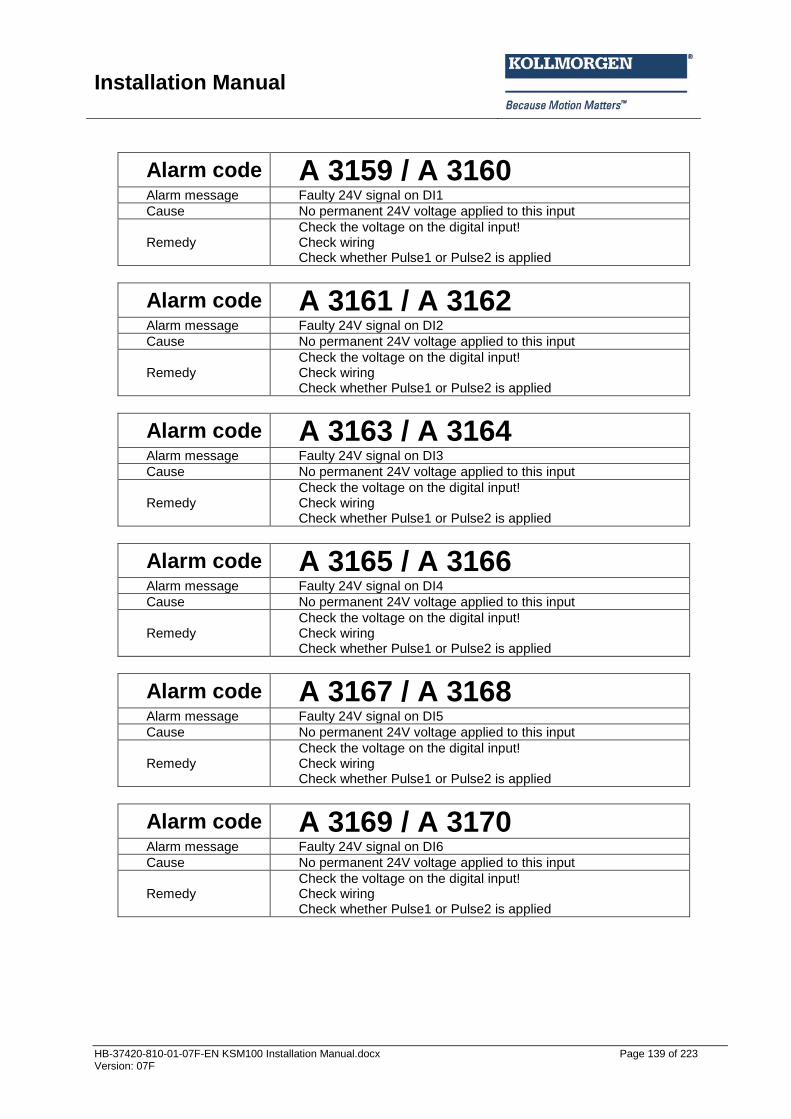
Installation Manual
HB-37420-810-01-07F-EN KSM100 Installation Manual.docx Page 139 of 223 Version: 07F
Alarm code A 3159 / A 3160 Alarm message Faulty 24V signal on DI1
Cause No permanent 24V voltage applied to this input
Remedy Check the voltage on the digital input! Check wiring Check whether Pulse1 or Pulse2 is applied
Alarm code A 3161 / A 3162 Alarm message Faulty 24V signal on DI2
Cause No permanent 24V voltage applied to this input
Remedy Check the voltage on the digital input! Check wiring Check whether Pulse1 or Pulse2 is applied
Alarm code A 3163 / A 3164 Alarm message Faulty 24V signal on DI3
Cause No permanent 24V voltage applied to this input
Remedy Check the voltage on the digital input! Check wiring Check whether Pulse1 or Pulse2 is applied
Alarm code A 3165 / A 3166 Alarm message Faulty 24V signal on DI4
Cause No permanent 24V voltage applied to this input
Remedy Check the voltage on the digital input! Check wiring Check whether Pulse1 or Pulse2 is applied
Alarm code A 3167 / A 3168 Alarm message Faulty 24V signal on DI5
Cause No permanent 24V voltage applied to this input
Remedy Check the voltage on the digital input! Check wiring Check whether Pulse1 or Pulse2 is applied
Alarm code A 3169 / A 3170 Alarm message Faulty 24V signal on DI6
Cause No permanent 24V voltage applied to this input
Remedy Check the voltage on the digital input! Check wiring Check whether Pulse1 or Pulse2 is applied

Installation Manual
HB-37420-810-01-07F-EN KSM100 Installation Manual.docx Page 140 of 223 Version: 07F
Alarm code A 3171 / A 3172 Alarm message Faulty 24V signal on DI7
Cause No permanent 24V voltage applied to this input
Remedy Check the voltage on the digital input! Check wiring Check whether Pulse1 or Pulse2 is applied
Alarm code A 3173 / A 3174 Alarm message Faulty 24V signal on DI8
Cause No permanent 24V voltage applied to this input
Remedy Check the voltage on the digital input! Check wiring Check whether Pulse1 or Pulse2 is applied
Alarm code A 3175 / A 3176 Alarm message Faulty 24V signal on DI9
Cause No permanent 24V voltage applied to this input
Remedy Check the voltage on the digital input! Check wiring Check whether Pulse1 or Pulse2 is applied
Alarm code A 3177 / A 3178 Alarm message Faulty 24V signal on DI10
Cause No permanent 24V voltage applied to this input
Remedy Check the voltage on the digital input! Check wiring Check whether Pulse1 or Pulse2 is applied
Alarm code A 3179 / A 3180 Alarm message Faulty 24V signal on DI11
Cause No permanent 24V voltage applied to this input
Remedy Check the voltage on the digital input! Check wiring Check whether Pulse1 or Pulse2 is applied
Alarm code A 3181 / A 3182 Alarm message Faulty 24V signal on DI12
Cause No permanent 24V voltage applied to this input
Remedy Check the voltage on the digital input! Check wiring Check whether Pulse1 or Pulse2 is applied
Alarm code A 3183 / A 3184 Alarm message Faulty 24V signal on DI13
Cause No permanent 24V voltage applied to this input
Remedy Check the voltage on the digital input! Check wiring Check whether Pulse1 or Pulse2 is applied

Installation Manual
HB-37420-810-01-07F-EN KSM100 Installation Manual.docx Page 141 of 223 Version: 07F
Alarm code A 3185 / A 3186 Alarm message Faulty 24V signal on DI14
Cause No permanent 24V voltage applied to this input
Remedy Check the voltage on the digital input! Check wiring Check whether Pulse1 or Pulse2 is applied
Alarm code A 3191 / A 3192 Alarm message Short-circuit fault digital inputs
Cause Short circuit between the digital inputs within the module
Remedy Consult the manufacturer
Alarm code A 3197 / A 3198 Alarm message Faulty OSSD input test
Cause OSSD test faulty
Remedy 24V check the input voltage on all OSSD inputs
Alarm code A 3209 / A 3210 Fault message Encoder supply voltage X31 faulty.
Cause Encoder supply voltage does not comply with configured threshold Component fault in module
Remedy Check configuration! Check encoder supply voltage Switch device off/on.

Installation Manual
HB-37420-810-01-07F-EN KSM100 Installation Manual.docx Page 142 of 223 Version: 07F
Alarm code A 3213 / A 3214 Fault message Encoder supply voltage X32 faulty.
Cause Encoder supply voltage does not comply with configured threshold Component fault in module
Remedy Check configuration! Check encoder supply voltage Switch device off/on.
Alarm code A 3225 / A 3226 Fault message Deviation Ain1 to AIn2 too big
Cause Different voltages on both inputs configured threshold too low
Remedy Check voltages on Ain1! Check configuration of threshold/input filter Switch device off/on.
Alarm code A 3227 / A 3228 Fault message Deviation Ain3 to AIn4 too big
Cause Different voltages on both inputs configured threshold too low
Remedy Check voltages on Ain1! Check configuration of threshold/input filter Switch device off/on.
Alarm code A 3229 / A 3230 Fault message Plausibility test for encoder voltage faulty
Cause Encoder voltage value
Remedy Check encoder voltage supply Check wiring of encoder voltage supply
Alarm code A 3231 / A 3232 Fault message Plausibility test for analog inputs faulty
Cause Fault in analog input signal
Remedy Check connection of analog inputs Analog input voltage out of range
Alarm code A 3233 / A 3234 Fault message Open-circuit monitoring AIN1 has triggered
Cause Open-circuit monitoring activated (< 1000mV)
Remedy Check configuration of activation/sensor Check sensor connection
Alarm code A 3235 / A 3236 Fault message Open-circuit monitoring AIN2 has triggered
Cause Open-circuit monitoring activated (< 1000mV)
Remedy Check configuration of activation/sensor Check sensor connection
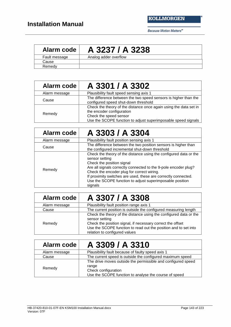
Installation Manual
HB-37420-810-01-07F-EN KSM100 Installation Manual.docx Page 143 of 223 Version: 07F
Alarm code A 3237 / A 3238 Fault message Analog adder overflow
Cause
Remedy
Alarm code A 3301 / A 3302 Alarm message Plausibility fault speed sensing axis 1
Cause The difference between the two speed sensors is higher than the configured speed shut-down threshold
Remedy
Check the theory of the distance once again using the data set in the encoder configuration Check the speed sensor Use the SCOPE function to adjust superimposable speed signals
Alarm code A 3303 / A 3304 Alarm message Plausibility fault position sensing axis 1
Cause The difference between the two position sensors is higher than the configured incremental shut-down threshold
Remedy
Check the theory of the distance using the configured data or the sensor setting Check the position signal Are all signals correctly connected to the 9-pole encoder plug? Check the encoder plug for correct wiring. If proximity switches are used, these are correctly connected. Use the SCOPE function to adjust superimposable position signals
Alarm code A 3307 / A 3308 Alarm message Plausibility fault position range axis 1
Cause The current position is outside the configured measuring length
Remedy
Check the theory of the distance using the configured data or the sensor setting Check the position signal, if necessary correct the offset Use the SCOPE function to read out the position and to set into relation to configured values
Alarm code A 3309 / A 3310 Alarm message Plausibility fault because of faulty speed axis 1
Cause The current speed is outside the configured maximum speed
Remedy
The drive moves outside the permissible and configured speed range Check configuration Use the SCOPE function to analyse the course of speed

Installation Manual
HB-37420-810-01-07F-EN KSM100 Installation Manual.docx Page 144 of 223 Version: 07F
Alarm code A 3311 / A 3312 Alarm message Configuration fault: Acceleration axis 1
Cause The current acceleration is outside the configured acceleration range
Remedy
The drive has exceeded the permissible acceleration range Check the configuration of maximum speed Use the SCOPE function to analyse the course of speed/acceleration
Alarm code A 3313 / A 3314 Fault message SSI sensor fault
Cause Encoder step change SSI-value within a cycle too big
Remedy Check encoder wiring Check encoder configuration
Alarm code A 3318 Fault message Incremental encoder axis 1 faulty
Cause Track A does not match track B
Remedy Check encoder wiring Check encoder configuration
Alarm code A 3321 / A 3322 Alarm message Plausibility fault speed sensing axis 2
Cause The difference between the two speed sensors is higher than the configured speed shut-down threshold
Remedy
Check the theory of the distance once again using the data set in the encoder configuration Check the speed sensor Use the SCOPE function to adjust superimposable speed signals
Alarm code A 3323 / A 3324 Alarm message Plausibility fault position sensing axis 2
Cause The difference between the two position sensors is higher than the configured incremental shut-down threshold
Remedy
Check the theory of the distance using the configured data or the sensor setting Check the position signal Are all signals correctly connected to the 9-pole encoder plug? Check the encoder plug for correct wiring. If proximity switches are used, these are correctly connected. Use the SCOPE function to adjust superimposable position signals
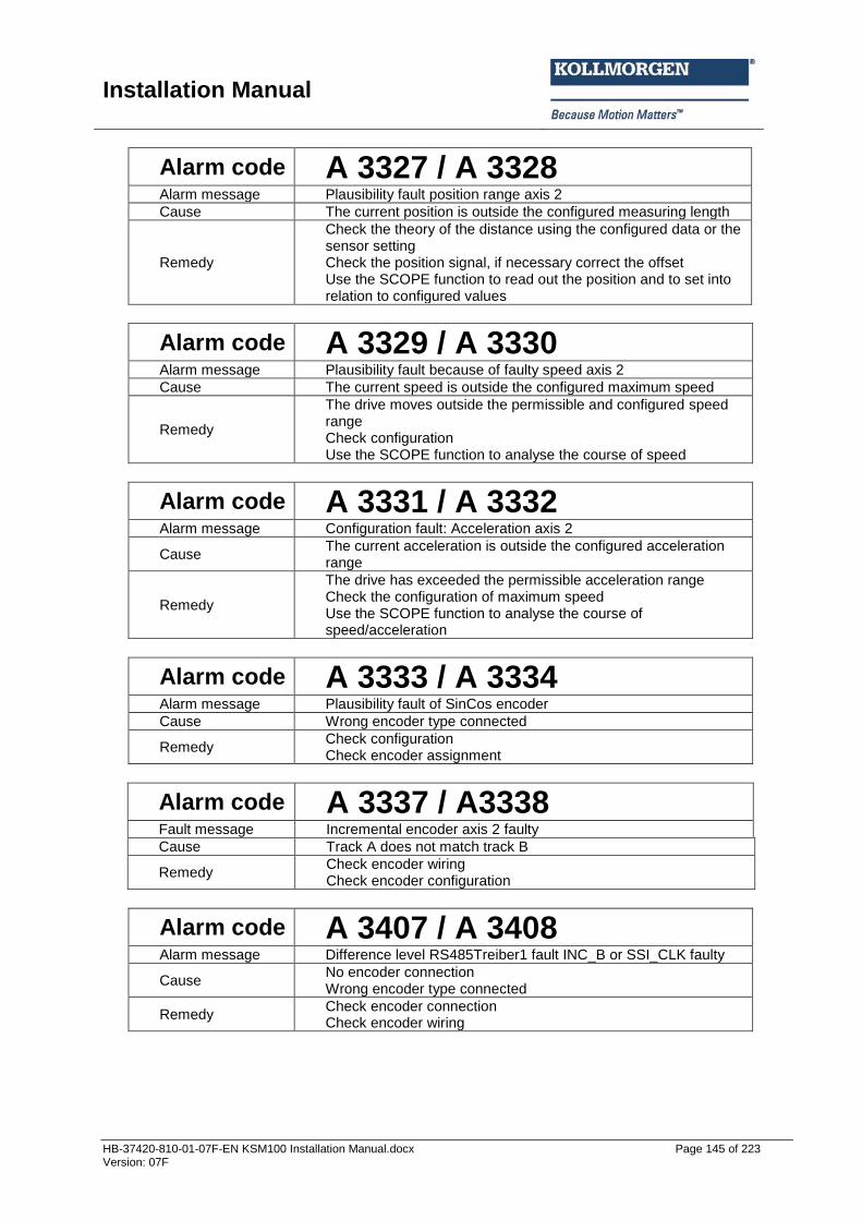
Installation Manual
HB-37420-810-01-07F-EN KSM100 Installation Manual.docx Page 145 of 223 Version: 07F
Alarm code A 3327 / A 3328 Alarm message Plausibility fault position range axis 2
Cause The current position is outside the configured measuring length
Remedy
Check the theory of the distance using the configured data or the sensor setting Check the position signal, if necessary correct the offset Use the SCOPE function to read out the position and to set into relation to configured values
Alarm code A 3329 / A 3330 Alarm message Plausibility fault because of faulty speed axis 2
Cause The current speed is outside the configured maximum speed
Remedy
The drive moves outside the permissible and configured speed range Check configuration Use the SCOPE function to analyse the course of speed
Alarm code A 3331 / A 3332 Alarm message Configuration fault: Acceleration axis 2
Cause The current acceleration is outside the configured acceleration range
Remedy
The drive has exceeded the permissible acceleration range Check the configuration of maximum speed Use the SCOPE function to analyse the course of speed/acceleration
Alarm code A 3333 / A 3334 Alarm message Plausibility fault of SinCos encoder
Cause Wrong encoder type connected
Remedy Check configuration Check encoder assignment
Alarm code A 3337 / A3338 Fault message Incremental encoder axis 2 faulty
Cause Track A does not match track B
Remedy Check encoder wiring Check encoder configuration
Alarm code A 3407 / A 3408 Alarm message Difference level RS485Treiber1 fault INC_B or SSI_CLK faulty
Cause No encoder connection Wrong encoder type connected
Remedy Check encoder connection Check encoder wiring
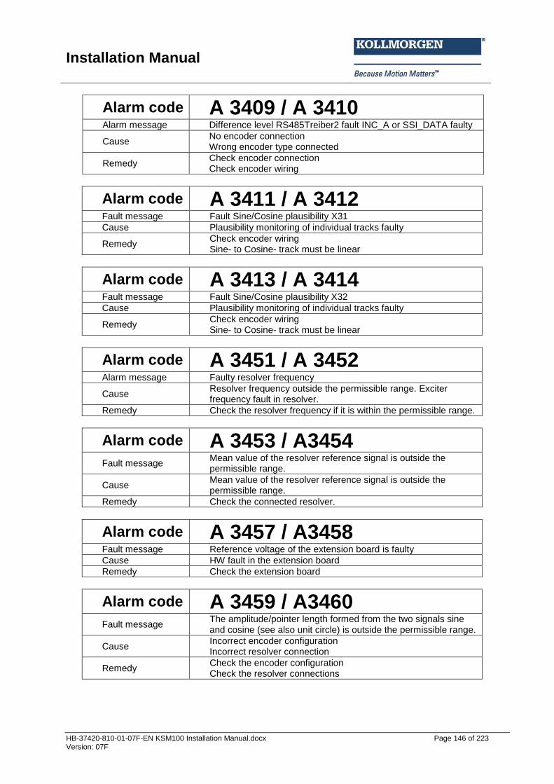
Installation Manual
HB-37420-810-01-07F-EN KSM100 Installation Manual.docx Page 146 of 223 Version: 07F
Alarm code A 3409 / A 3410 Alarm message Difference level RS485Treiber2 fault INC_A or SSI_DATA faulty
Cause No encoder connection Wrong encoder type connected
Remedy Check encoder connection Check encoder wiring
Alarm code A 3411 / A 3412 Fault message Fault Sine/Cosine plausibility X31
Cause Plausibility monitoring of individual tracks faulty
Remedy Check encoder wiring Sine- to Cosine- track must be linear
Alarm code A 3413 / A 3414 Fault message Fault Sine/Cosine plausibility X32
Cause Plausibility monitoring of individual tracks faulty
Remedy Check encoder wiring Sine- to Cosine- track must be linear
Alarm code A 3451 / A 3452 Alarm message Faulty resolver frequency
Cause Resolver frequency outside the permissible range. Exciter frequency fault in resolver.
Remedy Check the resolver frequency if it is within the permissible range.
Alarm code A 3453 / A3454 Fault message
Mean value of the resolver reference signal is outside the permissible range.
Cause Mean value of the resolver reference signal is outside the permissible range.
Remedy Check the connected resolver.
Alarm code A 3457 / A3458 Fault message Reference voltage of the extension board is faulty
Cause HW fault in the extension board
Remedy Check the extension board
Alarm code A 3459 / A3460 Fault message
The amplitude/pointer length formed from the two signals sine and cosine (see also unit circle) is outside the permissible range.
Cause Incorrect encoder configuration Incorrect resolver connection
Remedy Check the encoder configuration Check the resolver connections
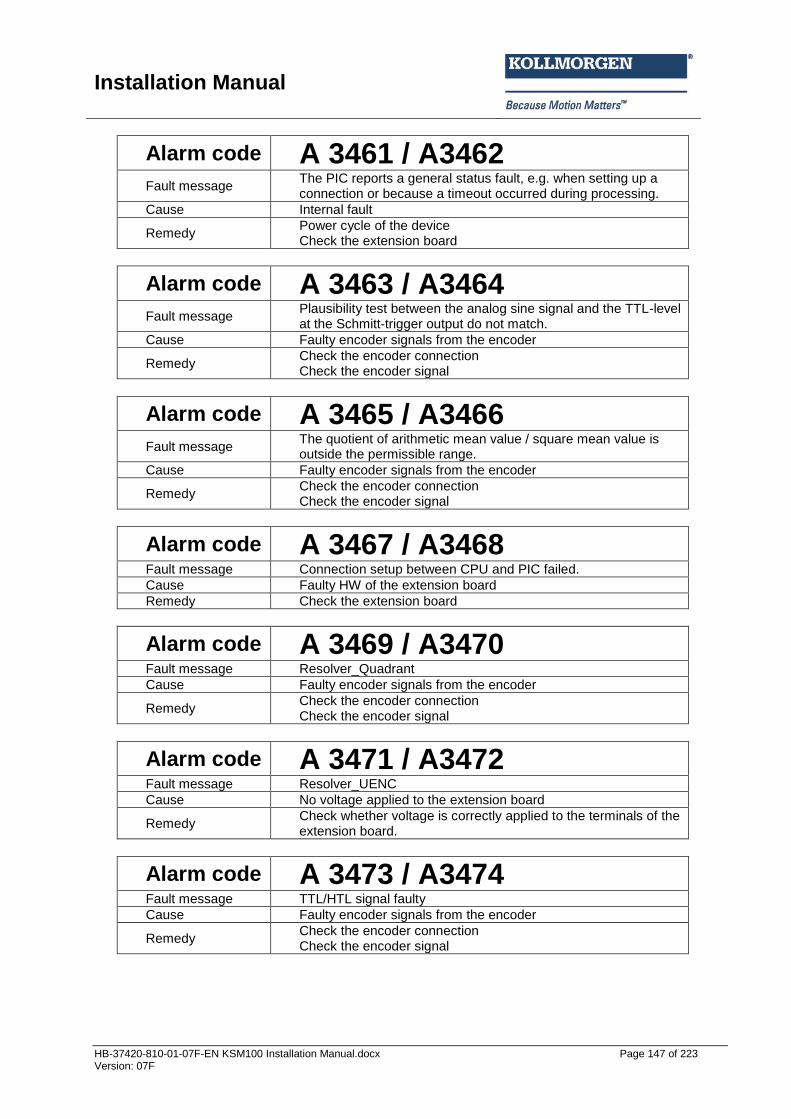
Installation Manual
HB-37420-810-01-07F-EN KSM100 Installation Manual.docx Page 147 of 223 Version: 07F
Alarm code A 3461 / A3462 Fault message
The PIC reports a general status fault, e.g. when setting up a connection or because a timeout occurred during processing.
Cause Internal fault
Remedy Power cycle of the device Check the extension board
Alarm code A 3463 / A3464 Fault message
Plausibility test between the analog sine signal and the TTL-level at the Schmitt-trigger output do not match.
Cause Faulty encoder signals from the encoder
Remedy Check the encoder connection Check the encoder signal
Alarm code A 3465 / A3466 Fault message
The quotient of arithmetic mean value / square mean value is outside the permissible range.
Cause Faulty encoder signals from the encoder
Remedy Check the encoder connection Check the encoder signal
Alarm code A 3467 / A3468 Fault message Connection setup between CPU and PIC failed. Cause Faulty HW of the extension board
Remedy Check the extension board
Alarm code A 3469 / A3470 Fault message Resolver_Quadrant
Cause Faulty encoder signals from the encoder
Remedy Check the encoder connection Check the encoder signal
Alarm code A 3471 / A3472 Fault message Resolver_UENC
Cause No voltage applied to the extension board
Remedy Check whether voltage is correctly applied to the terminals of the extension board.
Alarm code A 3473 / A3474 Fault message TTL/HTL signal faulty
Cause Faulty encoder signals from the encoder
Remedy Check the encoder connection Check the encoder signal

Installation Manual
HB-37420-810-01-07F-EN KSM100 Installation Manual.docx Page 148 of 223 Version: 07F
Alarm code A 3475 / A3476 Fault message Resolver_TRACE Fault
Cause Counting signals of the encoder are incorrect
Remedy Check the encoder connection Check the encoder signal Check the extension board
Alarm code A 3505 / A 3506 Fault message Read head fault WCS encoder system axis 1
Cause WCS read head has detected a fault
Remedy Read out fault types from WCS encoder system
Alarm code A 3507 / A 3508 Fault message Read head fault WCS encoder system axis 1
Cause WCS read head has detected a fault
Remedy Read out fault types from WCS encoder system
Alarm code A 3551 / A3552 Fault message SSI_ECE STATUS 1. axis SSI Ext Encoder
Cause Evaluation of the 1st status bit is faulty
Remedy Check the encoder connection Check the encoder signal Replace the SSI-encoder
Alarm code A 3553 / A3554 Fault message SSI_ECE STATUS 1. axis SSI Ext Encoder
Cause Evaluation of the 2nd status bit is faulty
Remedy Check the encoder connection Check the encoder signal Replace the SSI-encoder
Alarm code A 3555 / A3556 Fault message SSI_ECE STATUS 1. axis SSI Ext Encoder
Cause Evaluation of the 3rd status bit is faulty
Remedy Check the encoder connection Check the encoder signal Replace the SSI-encoder
Alarm code A 3557 / A3558 Fault message SSI_ECE STATUS 1. axis SSI Ext Encoder
Cause Evaluation of the 4th status bit is faulty
Remedy Check the encoder connection Check the encoder signal Replace the SSI-encoder
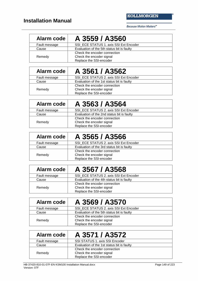
Installation Manual
HB-37420-810-01-07F-EN KSM100 Installation Manual.docx Page 149 of 223 Version: 07F
Alarm code A 3559 / A3560 Fault message SSI_ECE STATUS 1. axis SSI Ext Encoder
Cause Evaluation of the 5th status bit is faulty
Remedy Check the encoder connection Check the encoder signal Replace the SSI-encoder
Alarm code A 3561 / A3562 Fault message SSI_ECE STATUS 2. axis SSI Ext Encoder
Cause Evaluation of the 1st status bit is faulty
Remedy Check the encoder connection Check the encoder signal Replace the SSI-encoder
Alarm code A 3563 / A3564 Fault message SSI_ECE STATUS 2. axis SSI Ext Encoder
Cause Evaluation of the 2nd status bit is faulty
Remedy Check the encoder connection Check the encoder signal Replace the SSI-encoder
Alarm code A 3565 / A3566 Fault message SSI_ECE STATUS 2. axis SSI Ext Encoder
Cause Evaluation of the 3rd status bit is faulty
Remedy Check the encoder connection Check the encoder signal Replace the SSI-encoder
Alarm code A 3567 / A3568 Fault message SSI_ECE STATUS 2. axis SSI Ext Encoder
Cause Evaluation of the 4th status bit is faulty
Remedy Check the encoder connection Check the encoder signal Replace the SSI-encoder
Alarm code A 3569 / A3570 Fault message SSI_ECE STATUS 2. axis SSI Ext Encoder
Cause Evaluation of the 5th status bit is faulty
Remedy Check the encoder connection Check the encoder signal Replace the SSI-encoder
Alarm code A 3571 / A3572 Fault message SSI STATUS 1. axis SSI Encoder
Cause Evaluation of the 1st status bit is faulty
Remedy Check the encoder connection Check the encoder signal Replace the SSI-encoder
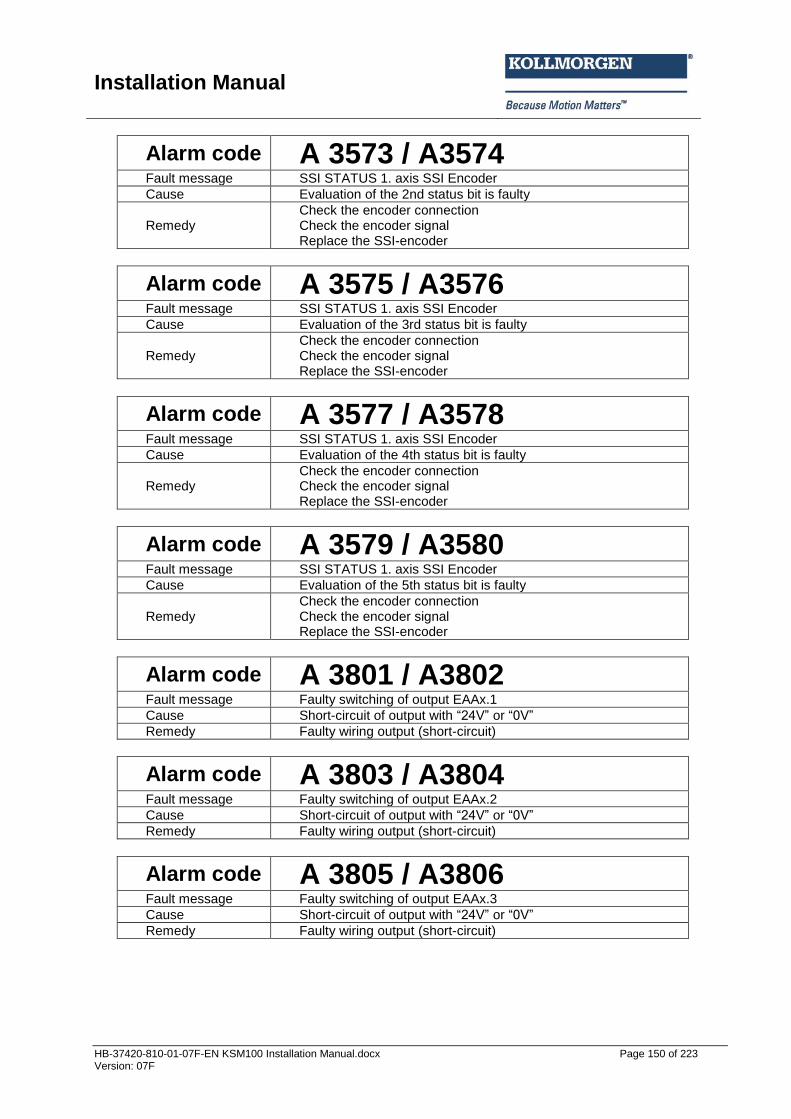
Installation Manual
HB-37420-810-01-07F-EN KSM100 Installation Manual.docx Page 150 of 223 Version: 07F
Alarm code A 3573 / A3574 Fault message SSI STATUS 1. axis SSI Encoder
Cause Evaluation of the 2nd status bit is faulty
Remedy Check the encoder connection Check the encoder signal Replace the SSI-encoder
Alarm code A 3575 / A3576 Fault message SSI STATUS 1. axis SSI Encoder
Cause Evaluation of the 3rd status bit is faulty
Remedy Check the encoder connection Check the encoder signal Replace the SSI-encoder
Alarm code A 3577 / A3578 Fault message SSI STATUS 1. axis SSI Encoder
Cause Evaluation of the 4th status bit is faulty
Remedy Check the encoder connection Check the encoder signal Replace the SSI-encoder
Alarm code A 3579 / A3580 Fault message SSI STATUS 1. axis SSI Encoder
Cause Evaluation of the 5th status bit is faulty
Remedy Check the encoder connection Check the encoder signal Replace the SSI-encoder
Alarm code A 3801 / A3802 Fault message Faulty switching of output EAAx.1
Cause Short-circuit of output with “24V” or “0V”
Remedy Faulty wiring output (short-circuit)
Alarm code A 3803 / A3804 Fault message Faulty switching of output EAAx.2
Cause Short-circuit of output with “24V” or “0V”
Remedy Faulty wiring output (short-circuit)
Alarm code A 3805 / A3806 Fault message Faulty switching of output EAAx.3
Cause Short-circuit of output with “24V” or “0V”
Remedy Faulty wiring output (short-circuit)

Installation Manual
HB-37420-810-01-07F-EN KSM100 Installation Manual.docx Page 151 of 223 Version: 07F
Alarm code A 3807 / A3808 Fault message Faulty switching of output EAAx.4
Cause Short-circuit of output with “24V” or “0V”
Remedy Faulty wiring output (short-circuit)
Alarm code A 3809 / A3810 Fault message Faulty switching of output EAAx.5
Cause Short-circuit of output with “24V” or “0V”
Remedy Faulty wiring output (short-circuit)
Alarm code A 3811 / A3812 Fault message Faulty switching of output EAAx.6
Cause Short-circuit of output with “24V” or “0V”
Remedy Faulty wiring output (short-circuit)
Alarm code A 3813 / A3814 Fault message Faulty switching of output EAAx.7
Cause Short-circuit of output with “24V” or “0V”
Remedy Faulty wiring output (short-circuit)
Alarm code A 3815 / A3816 Fault message Faulty switching of output EAAx.8
Cause Short-circuit of output with “24V” or “0V”
Remedy Faulty wiring output (short-circuit)
Alarm code A 3817 / A3818 Fault message Faulty switching of output EAAx.9
Cause Short-circuit of output with “24V” or “0V”
Remedy Faulty wiring output (short-circuit)
Alarm code A 3819 / A3820 Fault message Faulty switching of output EAAx.10
Cause Short-circuit of output with “24V” or “0V”
Remedy Faulty wiring output (short-circuit)
Alarm code A 3901 / A3902 Fault message Faulty switching of output EAA0.11
Cause Short-circuit of output with “24V” or “0V”
Remedy Faulty wiring output (short-circuit)
Alarm code A 3903 / A3904 Fault message Faulty switching of output EAA0.12
Cause Short-circuit of output with “24V” or “0V”
Remedy Faulty wiring output (short-circuit)

Installation Manual
HB-37420-810-01-07F-EN KSM100 Installation Manual.docx Page 152 of 223 Version: 07F
Alarm code A 3905 / A3906 Fault message Faulty switching of output EAA0.13
Cause Short-circuit of output with “24V” or “0V”
Remedy Faulty wiring output (short-circuit)
Alarm code A 3907 / A3908 Fault message Faulty switching of output EAA0.14
Cause Short-circuit of output with “24V” or “0V”
Remedy Faulty wiring output (short-circuit)
Alarm code A 3909 / A3910 Fault message Faulty switching of output EAA0.15
Cause Short-circuit of output with “24V” or “0V”
Remedy Faulty wiring output (short-circuit)
Alarm code A 3911 / A3912 Fault message Faulty switching of output EAA0.16
Cause Short-circuit of output with “24V” or “0V”
Remedy Faulty wiring output (short-circuit)
Alarm code A 3913 / A3914 Fault message Faulty switching of output EAA0.17
Cause Short-circuit of output with “24V” or “0V”
Remedy Faulty wiring output (short-circuit)
Alarm code A 3915 / A3916 Fault message Faulty switching of output EAA0.18
Cause Short-circuit of output with “24V” or “0V”
Remedy Faulty wiring output (short-circuit)
Alarm code A 3917 / A3918 Fault message Faulty switching of output EAA0.19
Cause Short-circuit of output with “24V” or “0V”
Remedy Faulty wiring output (short-circuit)
Alarm code A 3919 / A3920 Fault message Faulty switching of output EAAx.20
Cause Short-circuit of output with “24V” or “0V”
Remedy Faulty wiring output (short-circuit)
Alarm code A 3921 / A3922 Fault message Faulty switching of output EAAx.21
Cause Short-circuit of output with “24V” or “0V”
Remedy Faulty wiring output (short-circuit)

Installation Manual
HB-37420-810-01-07F-EN KSM100 Installation Manual.docx Page 153 of 223 Version: 07F
Alarm code A 3923 / A3924 Fault message Faulty switching of output EAAx.22
Cause Short-circuit of output with “24V” or “0V”
Remedy Faulty wiring output (short-circuit)
Alarm code A 3925 / A3926 Fault message Faulty switching of output EAAx.23
Cause Short-circuit of output with “24V” or “0V”
Remedy Faulty wiring output (short-circuit)
Alarm code A 3927 / A3928 Fault message Faulty switching of output EAAx.24
Cause Short-circuit of output with “24V” or “0V”
Remedy Faulty wiring output (short-circuit)
Alarm code A 3929 / A3930 Fault message Faulty switching of output EAAx.25
Cause Short-circuit of output with “24V” or “0V”
Remedy Faulty wiring output (short-circuit)
Alarm code A 3931 / A3932 Fault message Faulty switching of output EAAx.26
Cause Short-circuit of output with “24V” or “0V”
Remedy Faulty wiring output (short-circuit)
Alarm code A 3933 / A3934 Fault message Faulty switching of output EAAx.27
Cause Short-circuit of output with “24V” or “0V”
Remedy Faulty wiring output (short-circuit)
Alarm code A 3935 / A3936 Fault message Faulty switching of output EAAx.28
Cause Short-circuit of output with “24V” or “0V”
Remedy Faulty wiring output (short-circuit)
Alarm code A 3937 / A3938 Fault message Faulty switching of output EAAx.29
Cause Short-circuit of output ith “24V” or “0V”
Remedy Faulty wiring output (short-circuit)

Installation Manual
HB-37420-810-01-07F-EN KSM100 Installation Manual.docx Page 154 of 223 Version: 07F
Alarm code A 3939 / A3940 Fault message Faulty switching of output EAAx.30
Cause Short-circuit of output with “24V” or “0V”
Remedy Faulty wiring output (short-circuit)
Alarm code A 3941 / A3942 Fault message Faulty switching of output EAA0.31
Cause Short-circuit of output with “24V” or “0V”
Remedy Faulty wiring output (short-circuit)
Alarm code A 3943 / A3944 Fault message Faulty switching of output EAA0.32
Cause Short-circuit of output with “24V” or “0V”
Remedy Faulty wiring output (short-circuit)
Alarm code A 3945 / A3946 Fault message Faulty switching of output EAA0.33
Cause Short-circuit of output with “24V” or “0V”
Remedy Faulty wiring output (short-circuit)
Alarm code A 3947 / A3948 Fault message Faulty switching of output EAA0.34
Cause Short-circuit of output with “24V” or “0V”
Remedy Faulty wiring output (short-circuit)
Alarm code A 3949 / A3950 Fault message Faulty switching of output EAA0.35
Cause Short-circuit of output with “24V” or “0V”
Remedy Faulty wiring output (short-circuit)
Alarm code A 3951 / A3952 Fault message Faulty switching of output EAA0.36
Cause Short-circuit of output with “24V” or “0V”
Remedy Faulty wiring output (short-circuit)
Alarm code A 3953 / A3954 Fault message Faulty switching of output EAA0.37
Cause Short-circuit of output with “24V” or “0V”
Remedy Faulty wiring output (short-circuit)

Installation Manual
HB-37420-810-01-07F-EN KSM100 Installation Manual.docx Page 155 of 223 Version: 07F
Alarm code A 3955 / A3956 Fault message Faulty switching of output EAA0.38
Cause Short-circuit of output with “24V” or “0V”
Remedy Faulty wiring output (short-circuit)
Alarm code A 3957 / A3958 Fault message Faulty switching of output EAA0.39
Cause Short-circuit of output with “24V” or “0V”
Remedy Faulty wiring output (short-circuit)
Alarm code A 3959 / A3960 Fault message Faulty switching of output EAAx.40
Cause Short-circuit of output with “24V” or “0V”
Remedy Faulty wiring output (short-circuit)
Alarm code A 4001 / A 4002 Alarm message
CCW and CW rotation monitoring SDI1 activated at the same time
Cause Multiple activation
Remedy In programming make sure that onl one “Enable” is activated at a time
Alarm code A 4003 / A 4004 Alarm message
CCW and CW rotation monitoring SDI2 activated at the same time
Cause Multiple activation
Remedy In programming make sure that only one “Enable” is activated at a time
Alarm code A 4401 / A 4402 Alarm message Faulty EMU (ID1) monitoring
Cause Faulty examination of external switching contact axis module
Remedy Check feedback EMU (normally closed contact) Check control Check configuration of deceleration time
Alarm code A 4403 / A 4404 Alarm message Faulty EMU (ID2) monitoring
Cause Faulty examination of external switching contact axis module
Remedy Check feedback EMU (normally closed contact) Check control Check configuration of deceleration time
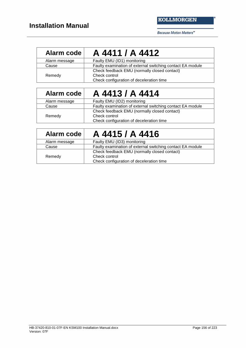
Installation Manual
HB-37420-810-01-07F-EN KSM100 Installation Manual.docx Page 156 of 223 Version: 07F
Alarm code A 4411 / A 4412 Alarm message Faulty EMU (ID1) monitoring
Cause Faulty examination of external switching contact EA module
Remedy Check feedback EMU (normally closed contact) Check control Check configuration of deceleration time
Alarm code A 4413 / A 4414 Alarm message Faulty EMU (ID2) monitoring
Cause Faulty examination of external switching contact EA module
Remedy Check feedback EMU (normally closed contact) Check control Check configuration of deceleration time
Alarm code A 4415 / A 4416 Alarm message Faulty EMU (ID3) monitoring
Cause Faulty examination of external switching contact EA module
Remedy Check feedback EMU (normally closed contact) Check control Check configuration of deceleration time

Installation Manual
HB-37420-810-01-07F-EN KSM100 Installation Manual.docx Page 157 of 223 Version: 07F
Alarm code A 4417 / A 4418 Alarm message Faulty EMU (ID4) monitoring
Cause Faulty examination of external switching contact EA module
Remedy Check feedback EMU (normally closed contact) Check control Check configuration of deceleration time
Alarm code A 4419 / A 4420 Alarm message Faulty EMU (ID5) monitoring
Cause Faulty examination of external switching contact EA module
Remedy Check feedback EMU (normally closed contact) Check control Check configuration of deceleration time
Alarm code A 4421 / A 4422 Alarm message Faulty EMU (ID6) monitoring
Cause Faulty examination of external switching contact EA module
Remedy Check feedback EMU (normally closed contact) Check control Check configuration of deceleration time
Alarm code A 4423 / A 4424 Alarm message Faulty EMU (ID7) monitoring
Cause Faulty examination of external switching contact EA module
Remedy Check feedback EMU (normally closed contact) Check control Check configuration of deceleration time
Alarm code A 4425 / A 4426 Alarm message Faulty EMU (ID8) monitoring
Cause Faulty examination of external switching contact EA module
Remedy Check feedback EMU (normally closed contact) Check control Check configuration of deceleration time
Alarm code A 4427 / A 4428 Alarm message Faulty EMU (ID9) monitoring
Cause Faulty examination of external switching contact EA module
Remedy Check feedback EMU (normally closed contact) Check control Check configuration of deceleration time
Alarm code A 4429 / A 4430 Alarm message Faulty EMU (ID10) monitoring
Cause Faulty examination of external switching contact EA module
Remedy Check feedback EMU (normally closed contact) Check control Check configuration of deceleration time

Installation Manual
HB-37420-810-01-07F-EN KSM100 Installation Manual.docx Page 158 of 223 Version: 07F
Alarm code A 4601 / A 4602 Alarm message Monitoring range left and right of SLP1 activated at the same time
Cause Multiple activation
Remedy In programming make sure that only one “Enable” is activated at a time
Alarm code A 4603 / A 4604 Alarm message Monitoring range left and right of SLP2 activated at the same time
Cause Multiple activation
Remedy In programming make sure that only one “Enable” is activated at a time
Alarm code A 4605 / A 4606 Alarm message SLP1 Teach-In Status Faults
Cause SET and QUIT input have a faulty switching sequence
Remedy Check input configuration Check switching sequence
Alarm code A 4607 / A 4608 Alarm message SLP 2 Teach In status fault
Cause SET and QUIT input have a faulty switching sequence
Remedy Check configuration Check switching sequence
Alarm code A 4609 / A 4610 Alarm message SLP1 Teach In position fault
Cause Teach In position outside the measuring range
Remedy Check transfer position
Alarm code A 4611 / A 4612 Alarm message SLP2 Teach In position fault Cause Teach In position outside the measuring range Remedy Check transfer position
Alarm code A 4613 / A 4614 Alarm message SLP1 Teach In SOS activation fault
Cause The drive moved during Teach In (SOS fault)
Remedy The drive must be stopped when using the Teach In function Check whether SOS has already triggered
Alarm code A 4615 / A 4616 Alarm message SLP 2 Teach In SOS activation fault
Cause The drive moved during Teach In (SOS fault)
Remedy The drive must be stopped when using the Teach In function Check whether SOS has already triggered

Installation Manual
HB-37420-810-01-07F-EN KSM100 Installation Manual.docx Page 159 of 223 Version: 07F
Alarm code A 4901 / A 4902 Alarm message CCW and CW rotation monitoring SLI1 activated at the same time
Cause Multiple activation
Remedy In programming make sure that only one “Enable” is activated at a time
Alarm code A 4903 / A 4904 Alarm message CCW and CW rotation monitoring SLI2 activated at the same time
Cause Multiple activation
Remedy In programming make sure that only one “Enable” is activated at a time
Alarm code A 5001 / A 5002 Alarm message Test deactivation of digital inputs 1...14 faulty
Cause Inputs are still active after deactivation
Remedy Check wiring of digital inputs
Alarm code A 5101 / A 5102 Alarm message Pulse fault EAE0.1
Cause Unexpected status of pulse input
Remedy Check wiring of digital inputs
Alarm code A 5103 / A 5104 Alarm message Pulse fault EAE0.2
Cause Unexpected status of pulse input
Remedy Check wiring of digital inputs
Alarm code A 5105 / A 5106 Alarm message Pulse fault EAE0.3
Cause Unexpected status of pulse input
Remedy Check wiring of digital inputs
Alarm code A 5107 / A 5108 Alarm message Pulse fault EAE0.4
Cause Unexpected status of pulse input
Remedy Check wiring of digital inputs
Alarm code A 5109 / A 5110 Alarm message Pulse fault EAE0.5
Cause Unexpected status of pulse input
Remedy Check wiring of digital inputs

Installation Manual
HB-37420-810-01-07F-EN KSM100 Installation Manual.docx Page 160 of 223 Version: 07F
Alarm code A 5111 / A 5112 Alarm message Pulse fault EAE0.6
Cause Unexpected status of pulse input
Remedy Check wiring of digital inputs
Alarm code A 5113 / A 5114 Alarm message Pulse fault EAE0.7
Cause Unexpected status of pulse input
Remedy Check wiring of digital inputs
Alarm code A 5115 / A 5116 Alarm message Pulse fault EAE0.8
Cause Unexpected status of pulse input
Remedy Check wiring of digital inputs
Alarm code A 5117 / A 5118 Alarm message Pulse fault EAE0.9
Cause Unexpected status of pulse input
Remedy Check wiring of digital inputs
Alarm code A 5119 / A 5120 Alarm message Pulse fault EAE0.10
Cause Unexpected status of pulse input
Remedy Check wiring of digital inputs
Alarm code A 5121 / A 5122 Alarm message Pulse fault EAE0.11
Cause Unexpected status of pulse input
Remedy Check wiring of digital inputs
Alarm code A 5123 / A 5124 Alarm message Pulse fault EAE0.12
Cause Unexpected status of pulse input
Remedy Check wiring of digital inputs
Alarm code A 5125 / A 5126 Alarm message Pulse fault EAE0.13
Cause Unexpected status of pulse input
Remedy Check wiring of digital inputs
Alarm code A 5127 / A 5128 Alarm message Pulse fault EAE0.14
Cause Unexpected status of pulse input
Remedy Check wiring of digital inputs

Installation Manual
HB-37420-810-01-07F-EN KSM100 Installation Manual.docx Page 161 of 223 Version: 07F
Alarm code A 5129 / A 5130 Alarm message Pulse fault EAE0.15
Cause Unexpected status of pulse input
Remedy Check wiring of digital inputs
Alarm code A 5131 / A 5132 Alarm message Pulse fault EAE0.16
Cause Unexpected status of pulse input
Remedy Check wiring of digital inputs
Alarm code A 5133 / A 5134 Alarm message Pulse fault EAE0.17
Cause Unexpected status of pulse input
Remedy Check wiring of digital inputs
Alarm code A 5135 / A 5136 Alarm message Pulse fault EAE0.18
Cause Unexpected status of pulse input
Remedy Check wiring of digital inputs
Alarm code A 5137 / A 5138 Alarm message Pulse fault EAE0.19
Cause Unexpected status of pulse input
Remedy Check wiring of digital inputs
Alarm code A 5139 / A 5140 Alarm message Pulse fault EAE0.20
Cause Unexpected status of pulse input
Remedy Check wiring of digital inputs
Alarm code A 5141 / A 5142 Alarm message Pulse fault EAE0.21
Cause Unexpected status of pulse input
Remedy Check wiring of digital inputs
Alarm code A 5143 / A 5144 Alarm message Pulse fault EAE0.22
Cause Unexpected status of pulse input
Remedy Check wiring of digital inputs

Installation Manual
HB-37420-810-01-07F-EN KSM100 Installation Manual.docx Page 162 of 223 Version: 07F
Alarm code A 5145 / A 5146 Alarm message Pulse fault EAE0.23
Cause Unexpected status of pulse input
Remedy Check wiring of digital inputs
Alarm code A 5147 / A 5148 Alarm message Pulse fault EAE0.24
Cause Unexpected status of pulse input
Remedy Check wiring of digital inputs
Alarm code A 5149 / A 5150 Alarm message Pulse fault EAE0.25
Cause Unexpected status of pulse input
Remedy Check wiring of digital inputs
Alarm code A 5151 / A 5152 Alarm message Pulse fault EAE0.26
Cause Unexpected status of pulse input
Remedy Check wiring of digital inputs
Alarm code A 5153 / A 5154 Alarm message Pulse fault EAE0.27
Cause Unexpected status of pulse input
Remedy Check wiring of digital inputs
Alarm code A 5155 / A 5156 Alarm message Pulse fault EAE0.28
Cause Unexpected status of pulse input
Remedy Check wiring of digital inputs
Alarm code A 5157 / A 5158 Alarm message Pulse fault EAE0.29
Cause Unexpected status of pulse input
Remedy Check wiring of digital inputs
Alarm code A 5159 / A 5160 Alarm message Pulse fault EAE0.30
Cause Unexpected status of pulse input
Remedy Check wiring of digital inputs

Installation Manual
HB-37420-810-01-07F-EN KSM100 Installation Manual.docx Page 163 of 223 Version: 07F
Alarm code A 5161 / A 5162 Alarm message Pulse fault EAE0.31
Cause Unexpected status of pulse input
Remedy Check wiring of digital inputs
Alarm code A 5163 / A 5164 Alarm message Pulse fault EAE0.32
Cause Unexpected status of pulse input
Remedy Check wiring of digital inputs
Alarm code A 5165 / A 5166 Alarm message Pulse fault EAE0.33
Cause Unexpected status of pulse input
Remedy Check wiring of digital inputs
Alarm code A 5167 / A 5168 Alarm message Pulse fault EAE0.34
Cause Unexpected status of pulse input
Remedy Check wiring of digital inputs
Alarm code A 5169 / A 5170 Alarm message Pulse fault EAE0.35
Cause Unexpected status of pulse input
Remedy Check wiring of digital inputs
Alarm code A 5171 / A 5172 Alarm message Pulse fault EAE0.36
Cause Unexpected status of pulse input
Remedy Check wiring of digital inputs
Alarm code A 5173 / A 5174 Alarm message Pulse fault EAE0.37
Cause Unexpected status of pulse input
Remedy Check wiring of digital inputs
Alarm code A 5175 / A 5176 Alarm message Pulse fault EAE0.38
Cause Unexpected status of pulse input
Remedy Check wiring of digital inputs

Installation Manual
HB-37420-810-01-07F-EN KSM100 Installation Manual.docx Page 164 of 223 Version: 07F
Alarm code A 5177 / A 5178 Alarm message Pulse fault EAE0.39
Cause Unexpected status of pulse input
Remedy Check wiring of digital inputs
Alarm code A 5179 / A 5180 Alarm message Pulse fault EAE0.40
Cause Unexpected status of pulse input
Remedy Check wiring of digital inputs
Alarm code A 6701 / A 6702 Alarm message Timeout fault MET
Cause Input element with time monitoring is faulty
Remedy Check wiring of input element Input element faulty
Alarm code A 6703 / A 6704 Alarm message Timeout fault MEZ
Cause Two-hand control element with time monitoring is faulty
Remedy Check wiring of input element Input element faulty

Installation Manual
HB-37420-810-01-07F-EN KSM100 Installation Manual.docx Page 165 of 223 Version: 07F
Fatal Fault list KSM100
Fatal Error Code F 1001 Fault message
Configuration data were incorrectly loaded into the monitoring device
Cause Disturbed connection when loading the program into the monitoring device.
Remedy Reload the configuration data, then switch module off/on.
Fatal Error Code F 1003 Fault message Configuration data invalid for software version of module!
Cause Module configured with incorrect software version of the programming desktop.
Remedy Parameterize the module with the approved version of the programming desktop, the switch the module off/on.
Fatal Error Code F 1007 Fault message Device not programmed with the correct programming desktop
Cause Program or configuration data transferred to the device using the wrong programming desktop
Remedy Check the module design and parameterize again with a valid programming desktop. Then switch device off/on.
Fatal Error Code F 1307 Fault message Fault when deleting configuration data from the Flash Memory
Fatal Error Code F 1311 / F1312 Fault message Internal fault – please contact the manufacturer!
Fatal Error Code F 1314 Fault message Internal fault – please contact the manufacturer!
Fatal Error Code F 1330 Fault message Internal fault – please contact the manufacturer!
Fatal Error Code F 1401 / F 1402 Fault message Internal fault – please contact the manufacturer!
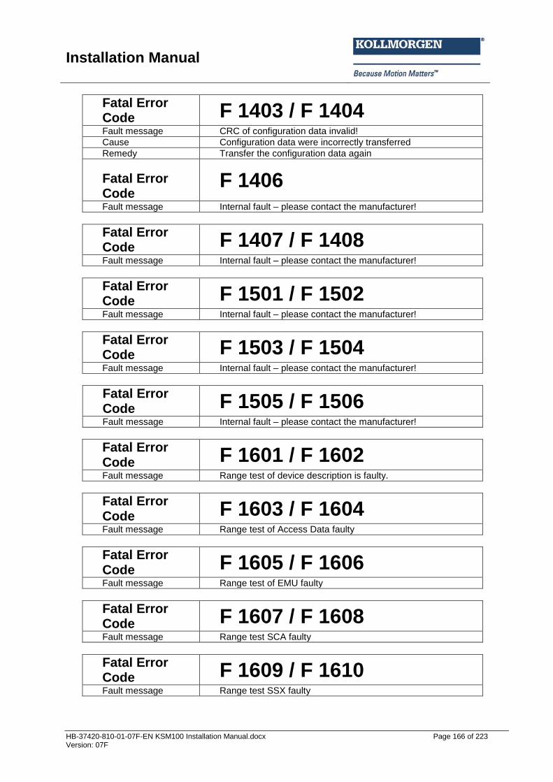
Installation Manual
HB-37420-810-01-07F-EN KSM100 Installation Manual.docx Page 166 of 223 Version: 07F
Fatal Error Code F 1403 / F 1404 Fault message CRC of configuration data invalid!
Cause Configuration data were incorrectly transferred
Remedy Transfer the configuration data again
Fatal Error Code
F 1406 Fault message Internal fault – please contact the manufacturer!
Fatal Error Code F 1407 / F 1408 Fault message Internal fault – please contact the manufacturer!
Fatal Error Code F 1501 / F 1502 Fault message Internal fault – please contact the manufacturer!
Fatal Error Code F 1503 / F 1504 Fault message Internal fault – please contact the manufacturer!
Fatal Error Code F 1505 / F 1506 Fault message Internal fault – please contact the manufacturer!
Fatal Error Code F 1601 / F 1602 Fault message Range test of device description is faulty.
Fatal Error Code F 1603 / F 1604 Fault message Range test of Access Data faulty
Fatal Error Code F 1605 / F 1606 Fault message Range test of EMU faulty
Fatal Error Code F 1607 / F 1608 Fault message Range test SCA faulty
Fatal Error Code F 1609 / F 1610 Fault message Range test SSX faulty
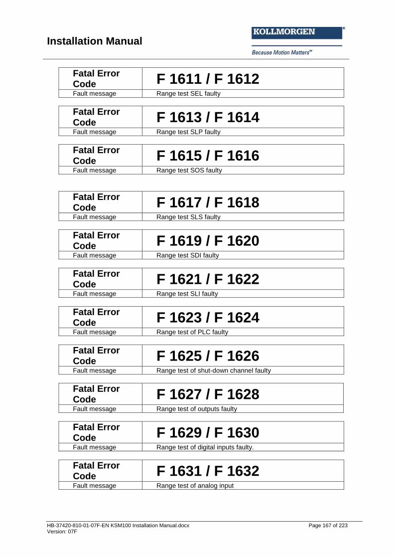
Installation Manual
HB-37420-810-01-07F-EN KSM100 Installation Manual.docx Page 167 of 223 Version: 07F
Fatal Error Code F 1611 / F 1612 Fault message Range test SEL faulty
Fatal Error Code F 1613 / F 1614 Fault message Range test SLP faulty
Fatal Error Code F 1615 / F 1616 Fault message Range test SOS faulty
Fatal Error Code F 1617 / F 1618 Fault message Range test SLS faulty
Fatal Error Code F 1619 / F 1620 Fault message Range test SDI faulty
Fatal Error Code F 1621 / F 1622 Fault message Range test SLI faulty
Fatal Error Code F 1623 / F 1624 Fault message Range test of PLC faulty
Fatal Error Code F 1625 / F 1626 Fault message Range test of shut-down channel faulty
Fatal Error Code F 1627 / F 1628 Fault message Range test of outputs faulty
Fatal Error Code F 1629 / F 1630 Fault message Range test of digital inputs faulty.
Fatal Error Code F 1631 / F 1632 Fault message Range test of analog input
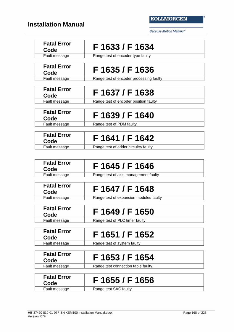
Installation Manual
HB-37420-810-01-07F-EN KSM100 Installation Manual.docx Page 168 of 223 Version: 07F
Fatal Error Code F 1633 / F 1634 Fault message Range test of encoder type faulty
Fatal Error Code F 1635 / F 1636 Fault message Range test of encoder processing faulty
Fatal Error Code F 1637 / F 1638 Fault message Range test of encoder position faulty
Fatal Error Code F 1639 / F 1640 Fault message Range test of PDM faulty.
Fatal Error Code F 1641 / F 1642 Fault message Range test of adder circuitry faulty
Fatal Error Code F 1645 / F 1646 Fault message Range test of axis management faulty
Fatal Error Code F 1647 / F 1648 Fault message Range test of expansion modules faulty
Fatal Error Code F 1649 / F 1650 Fault message Range test of PLC timer faulty
Fatal Error Code F 1651 / F 1652 Fault message Range test of system faulty
Fatal Error Code F 1653 / F 1654 Fault message Range test connection table faulty
Fatal Error Code F 1655 / F 1656 Fault message Range test SAC faulty
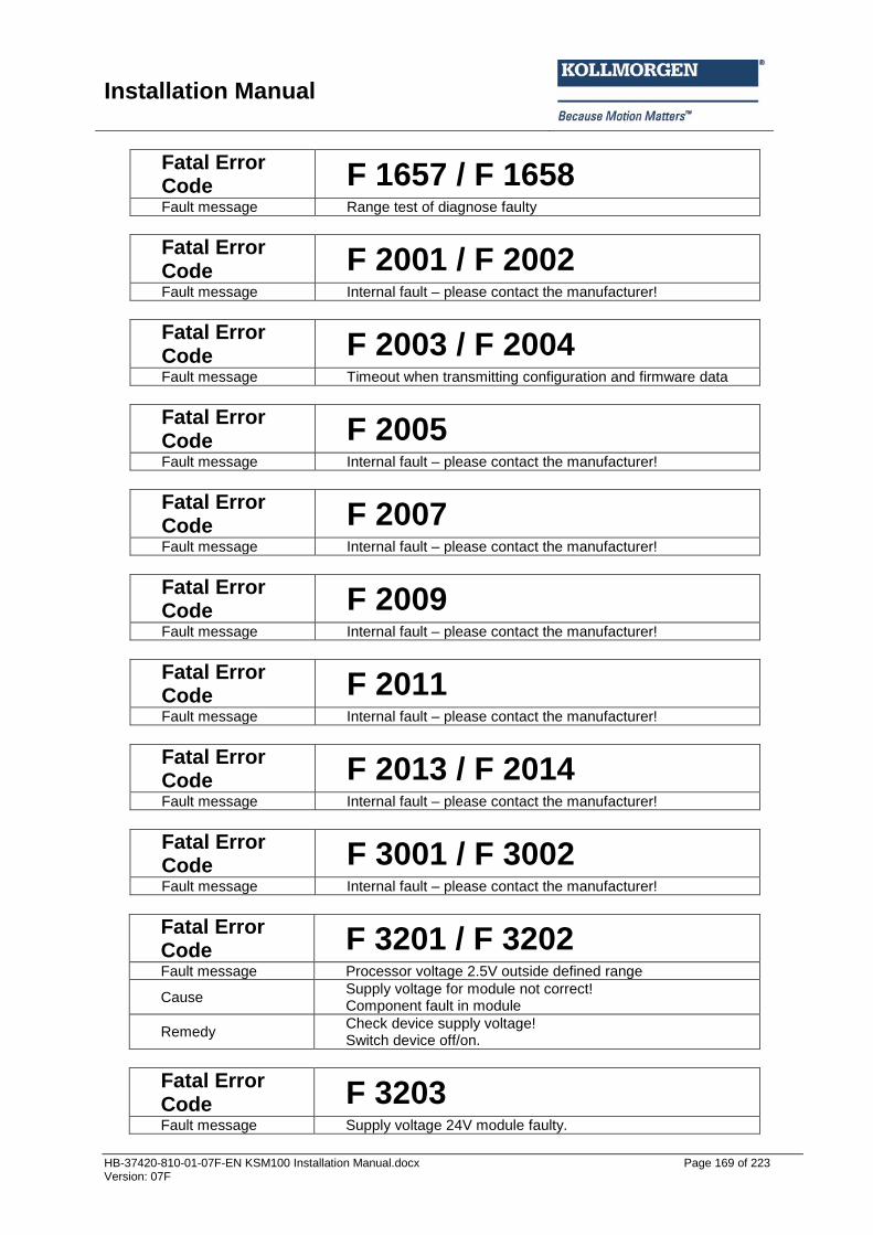
Installation Manual
HB-37420-810-01-07F-EN KSM100 Installation Manual.docx Page 169 of 223 Version: 07F
Fatal Error Code F 1657 / F 1658 Fault message Range test of diagnose faulty
Fatal Error Code F 2001 / F 2002 Fault message Internal fault – please contact the manufacturer!
Fatal Error Code F 2003 / F 2004 Fault message Timeout when transmitting configuration and firmware data
Fatal Error Code F 2005 Fault message Internal fault – please contact the manufacturer!
Fatal Error Code F 2007 Fault message Internal fault – please contact the manufacturer!
Fatal Error Code F 2009 Fault message Internal fault – please contact the manufacturer!
Fatal Error Code F 2011 Fault message Internal fault – please contact the manufacturer!
Fatal Error Code F 2013 / F 2014 Fault message Internal fault – please contact the manufacturer!
Fatal Error Code F 3001 / F 3002 Fault message Internal fault – please contact the manufacturer!
Fatal Error Code F 3201 / F 3202 Fault message Processor voltage 2.5V outside defined range
Cause Supply voltage for module not correct! Component fault in module
Remedy Check device supply voltage! Switch device off/on.
Fatal Error Code F 3203 Fault message Supply voltage 24V module faulty.
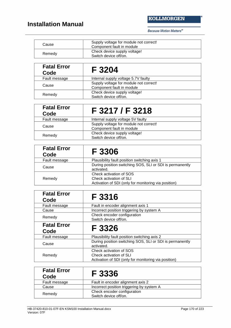
Installation Manual
HB-37420-810-01-07F-EN KSM100 Installation Manual.docx Page 170 of 223 Version: 07F
Cause Supply voltage for module not correct! Component fault in module
Remedy Check device supply voltage! Switch device off/on.
Fatal Error Code F 3204 Fault message Internal supply voltage 5.7V faulty
Cause Supply voltage for module not correct! Component fault in module
Remedy Check device supply voltage! Switch device off/on.
Fatal Error Code F 3217 / F 3218 Fault message Internal supply voltage 5V faulty
Cause Supply voltage for module not correct! Component fault in module
Remedy Check device supply voltage! Switch device off/on.
Fatal Error Code F 3306 Fault message Plausibility fault position switching axis 1
Cause During position switching SOS, SLI or SDI is permanently activated.
Remedy Check activation of SOS Check activation of SLI Activation of SDI (only for monitoring via position)
Fatal Error Code F 3316 Fault message Fault in encoder alignment axis 1
Cause Incorrect position triggering by system A
Remedy Check encoder configuration Switch device off/on.
Fatal Error Code F 3326 Fault message Plausibility fault position switching axis 2
Cause During position switching SOS, SLI or SDI is permanently activated.
Remedy Check activation of SOS Check activation of SLI Activation of SDI (only for monitoring via position)
Fatal Error Code F 3336 Fault message Fault in encoder alignment axis 2
Cause Incorrect position triggering by system A
Remedy Check encoder configuration Switch device off/on.
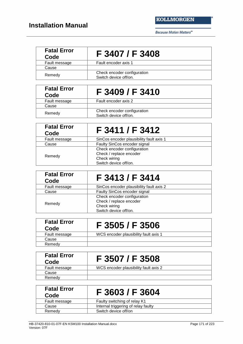
Installation Manual
HB-37420-810-01-07F-EN KSM100 Installation Manual.docx Page 171 of 223 Version: 07F
Fatal Error Code F 3407 / F 3408 Fault message Fault encoder axis 1
Cause
Remedy Check encoder configuration Switch device off/on.
Fatal Error Code F 3409 / F 3410 Fault message Fault encoder axis 2
Cause
Remedy Check encoder configuration Switch device off/on.
Fatal Error Code F 3411 / F 3412 Fault message SinCos encoder plausibility fault axis 1
Cause Faulty SinCos encoder signal
Remedy
Check encoder configuration Check / replace encoder Check wiring Switch device off/on.
Fatal Error Code F 3413 / F 3414 Fault message SinCos encoder plausibility fault axis 2
Cause Faulty SinCos encoder signal
Remedy
Check encoder configuration Check / replace encoder Check wiring Switch device off/on.
Fatal Error Code F 3505 / F 3506 Fault message WCS encoder plausibility fault axis 1
Cause
Remedy
Fatal Error Code F 3507 / F 3508 Fault message WCS encoder plausibility fault axis 2
Cause
Remedy
Fatal Error Code F 3603 / F 3604 Fault message Faulty switching of relay K1
Cause Internal triggering of relay faulty
Remedy Switch device off/on
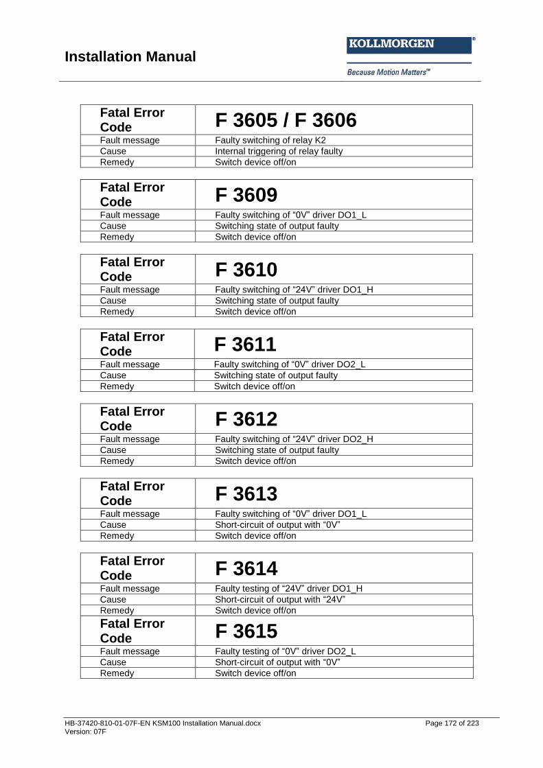
Installation Manual
HB-37420-810-01-07F-EN KSM100 Installation Manual.docx Page 172 of 223 Version: 07F
Fatal Error Code F 3605 / F 3606 Fault message Faulty switching of relay K2
Cause Internal triggering of relay faulty
Remedy Switch device off/on
Fatal Error Code F 3609 Fault message Faulty switching of “0V” driver DO1_L
Cause Switching state of output faulty
Remedy Switch device off/on
Fatal Error Code F 3610 Fault message Faulty switching of “24V” driver DO1_H
Cause Switching state of output faulty
Remedy Switch device off/on
Fatal Error Code F 3611 Fault message Faulty switching of “0V” driver DO2_L
Cause Switching state of output faulty
Remedy Switch device off/on
Fatal Error Code F 3612 Fault message Faulty switching of “24V” driver DO2_H
Cause Switching state of output faulty
Remedy Switch device off/on
Fatal Error Code F 3613 Fault message Faulty switching of “0V” driver DO1_L
Cause Short-circuit of output with “0V”
Remedy Switch device off/on
Fatal Error Code F 3614 Fault message Faulty testing of “24V” driver DO1_H
Cause Short-circuit of output with “24V”
Remedy Switch device off/on
Fatal Error Code F 3615 Fault message Faulty testing of “0V” driver DO2_L
Cause Short-circuit of output with “0V”
Remedy Switch device off/on
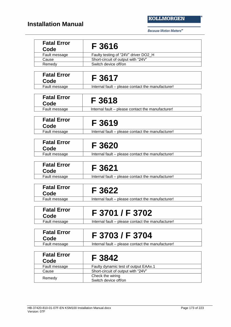
Installation Manual
HB-37420-810-01-07F-EN KSM100 Installation Manual.docx Page 173 of 223 Version: 07F
Fatal Error Code F 3616 Fault message Faulty testing of “24V” driver DO2_H
Cause Short-circuit of output with “24V”
Remedy Switch device off/on
Fatal Error Code F 3617 Fault message Internal fault – please contact the manufacturer!
Fatal Error Code F 3618 Fault message Internal fault – please contact the manufacturer!
Fatal Error Code F 3619 Fault message Internal fault – please contact the manufacturer!
Fatal Error Code F 3620 Fault message Internal fault – please contact the manufacturer!
Fatal Error Code F 3621 Fault message Internal fault – please contact the manufacturer!
Fatal Error Code F 3622 Fault message Internal fault – please contact the manufacturer!
Fatal Error Code F 3701 / F 3702 Fault message Internal fault – please contact the manufacturer!
Fatal Error Code F 3703 / F 3704 Fault message Internal fault – please contact the manufacturer!
Fatal Error Code F 3842 Fault message Faulty dynamic test of output EAAx.1
Cause Short-circuit of output with “24V”
Remedy Check the wiring Switch device off/on
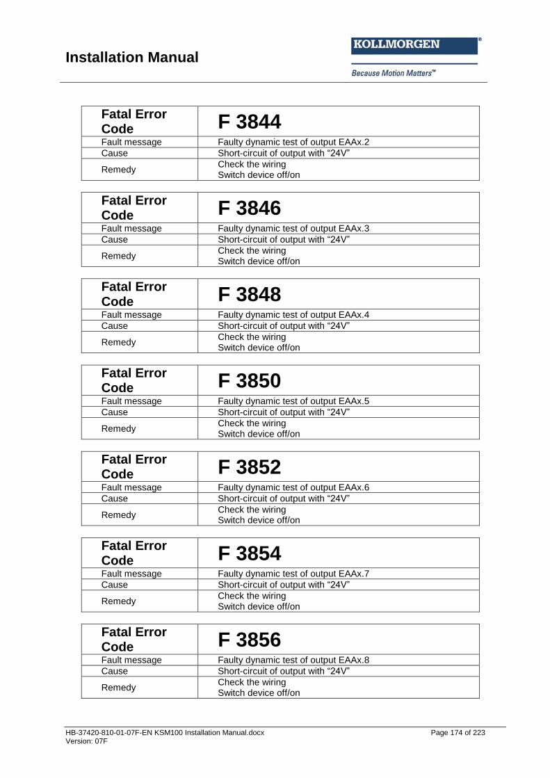
Installation Manual
HB-37420-810-01-07F-EN KSM100 Installation Manual.docx Page 174 of 223 Version: 07F
Fatal Error Code F 3844 Fault message Faulty dynamic test of output EAAx.2
Cause Short-circuit of output with “24V”
Remedy Check the wiring Switch device off/on
Fatal Error Code F 3846 Fault message Faulty dynamic test of output EAAx.3
Cause Short-circuit of output with “24V”
Remedy Check the wiring Switch device off/on
Fatal Error Code F 3848 Fault message Faulty dynamic test of output EAAx.4
Cause Short-circuit of output with “24V”
Remedy Check the wiring Switch device off/on
Fatal Error Code F 3850 Fault message Faulty dynamic test of output EAAx.5
Cause Short-circuit of output with “24V”
Remedy Check the wiring Switch device off/on
Fatal Error Code F 3852 Fault message Faulty dynamic test of output EAAx.6
Cause Short-circuit of output with “24V”
Remedy Check the wiring Switch device off/on
Fatal Error Code F 3854 Fault message Faulty dynamic test of output EAAx.7
Cause Short-circuit of output with “24V”
Remedy Check the wiring Switch device off/on
Fatal Error Code F 3856 Fault message Faulty dynamic test of output EAAx.8
Cause Short-circuit of output with “24V”
Remedy Check the wiring Switch device off/on
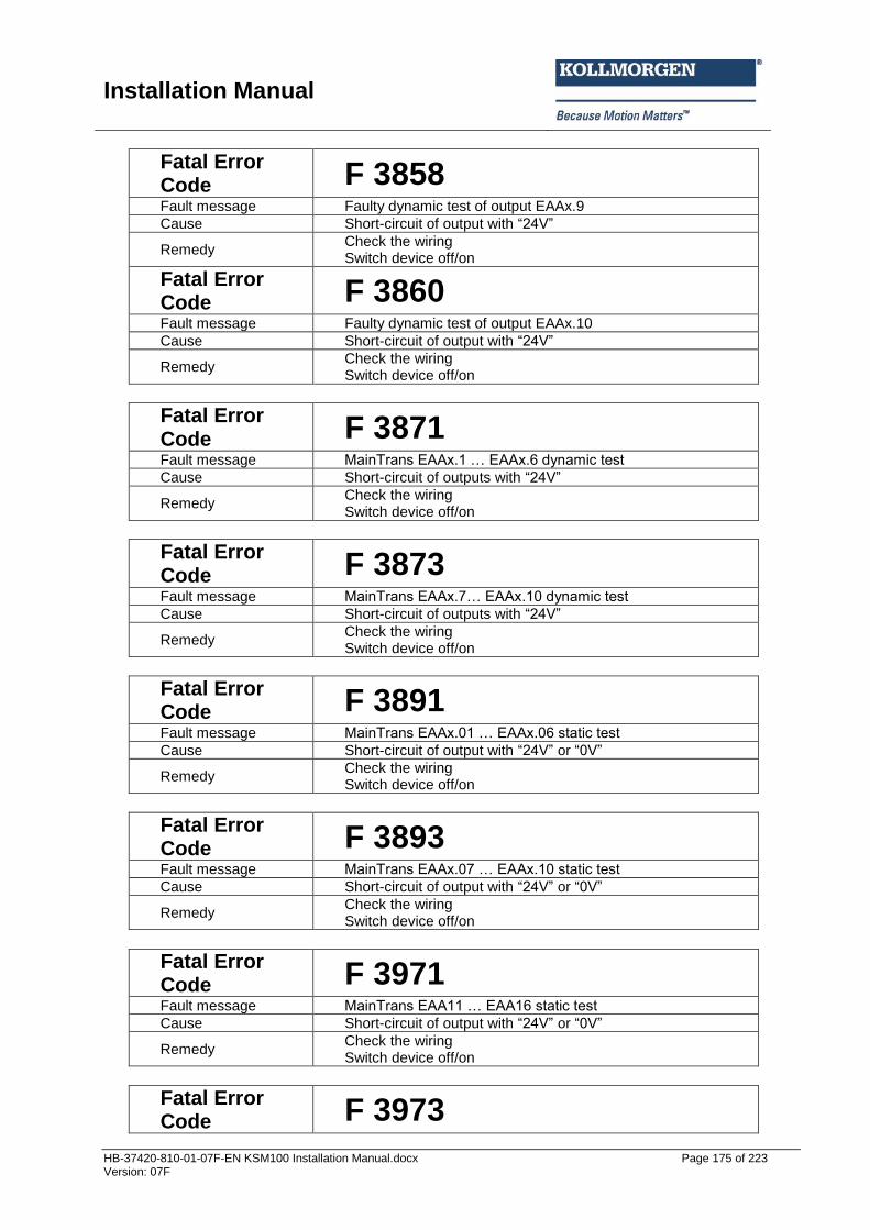
Installation Manual
HB-37420-810-01-07F-EN KSM100 Installation Manual.docx Page 175 of 223 Version: 07F
Fatal Error Code F 3858 Fault message Faulty dynamic test of output EAAx.9
Cause Short-circuit of output with “24V”
Remedy Check the wiring Switch device off/on
Fatal Error Code F 3860 Fault message Faulty dynamic test of output EAAx.10
Cause Short-circuit of output with “24V”
Remedy Check the wiring Switch device off/on
Fatal Error Code F 3871 Fault message MainTrans EAAx.1 … EAAx.6 d namic test
Cause Short-circuit of outputs with “24V”
Remedy Check the wiring Switch device off/on
Fatal Error Code F 3873 Fault message MainTrans EAAx.7… EAAx.10 d namic test
Cause Short-circuit of outputs with “24V”
Remedy Check the wiring Switch device off/on
Fatal Error Code F 3891 Fault message MainTrans EAAx.01 … EAAx.06 static test
Cause Short-circuit of output with “24V” or “0V”
Remedy Check the wiring Switch device off/on
Fatal Error Code F 3893 Fault message MainTrans EAAx.07 … EAAx.10 static test
Cause Short-circuit of output with “24V” or “0V”
Remedy Check the wiring Switch device off/on
Fatal Error Code F 3971 Fault message MainTrans EAA11 … EAA16 static test
Cause Short-circuit of output with “24V” or “0V”
Remedy Check the wiring Switch device off/on
Fatal Error Code F 3973
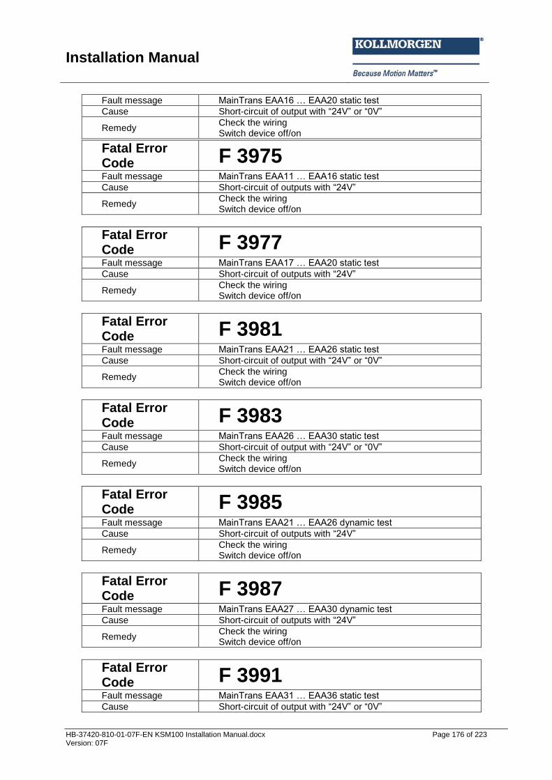
Installation Manual
HB-37420-810-01-07F-EN KSM100 Installation Manual.docx Page 176 of 223 Version: 07F
Fault message MainTrans EAA16 … EAA20 static test
Cause Short-circuit of output with “24V” or “0V”
Remedy Check the wiring Switch device off/on
Fatal Error Code F 3975 Fault message MainTrans EAA11 … EAA16 static test
Cause Short-circuit of outputs with “24V”
Remedy Check the wiring Switch device off/on
Fatal Error Code F 3977 Fault message MainTrans EAA17 … EAA20 static test
Cause Short-circuit of outputs with “24V”
Remedy Check the wiring Switch device off/on
Fatal Error Code F 3981 Fault message MainTrans EAA21 … EAA26 static test
Cause Short-circuit of output with “24V” or “0V”
Remedy Check the wiring Switch device off/on
Fatal Error Code F 3983 Fault message MainTrans EAA26 … EAA30 static test
Cause Short-circuit of output with “24V” or “0V”
Remedy Check the wiring Switch device off/on
Fatal Error Code F 3985 Fault message MainTrans EAA21 … EAA26 d namic test
Cause Short-circuit of outputs with “24V”
Remedy Check the wiring Switch device off/on
Fatal Error Code F 3987 Fault message MainTrans EAA27 … EAA30 d namic test
Cause Short-circuit of outputs with “24V”
Remedy Check the wiring Switch device off/on
Fatal Error Code F 3991 Fault message MainTrans EAA31 … EAA36 static test
Cause Short-circuit of output with “24V” or “0V”
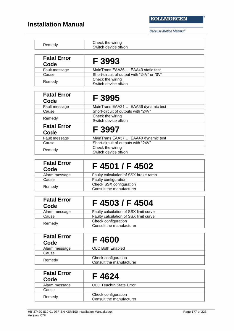
Installation Manual
HB-37420-810-01-07F-EN KSM100 Installation Manual.docx Page 177 of 223 Version: 07F
Remedy Check the wiring Switch device off/on
Fatal Error Code F 3993 Fault message MainTrans EAA36 … EAA40 static test
Cause Short-circuit of output with “24V” or “0V”
Remedy Check the wiring Switch device off/on
Fatal Error Code F 3995 Fault message MainTrans EAA31 … EAA36 d namic test
Cause Short-circuit of outputs with “24V”
Remedy Check the wiring Switch device off/on
Fatal Error Code F 3997 Fault message MainTrans EAA37 … EAA40 d namic test
Cause Short-circuit of outputs with “24V”
Remedy Check the wiring Switch device off/on
Fatal Error Code F 4501 / F 4502 Alarm message Faulty calculation of SSX brake ramp
Cause Faulty configuration
Remedy Check SSX configuration Consult the manufacturer
Fatal Error Code F 4503 / F 4504 Alarm message Faulty calculation of SSX limit curve
Cause Faulty calculation of SSX limit curve
Remedy Check configuration Consult the manufacturer
Fatal Error Code F 4600 Alarm message OLC Both Enabled
Cause
Remedy Check configuration Consult the manufacturer
Fatal Error Code F 4624 Alarm message OLC TeachIn State Error
Cause
Remedy Check configuration Consult the manufacturer
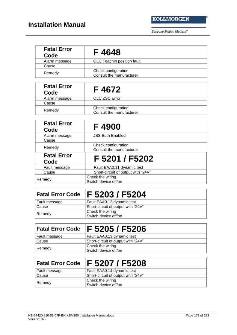
Installation Manual
HB-37420-810-01-07F-EN KSM100 Installation Manual.docx Page 178 of 223 Version: 07F
Fatal Error Code F 4648 Alarm message OLC TeachIn position fault
Cause
Remedy Check configuration Consult the manufacturer
Fatal Error Code F 4672 Alarm message OLC ZSC Error
Cause
Remedy Check configuration Consult the manufacturer
Fatal Error Code F 4900 Alarm message JSS Both Enabled
Cause
Remedy Check configuration Consult the manufacturer
Fatal Error Code F 5201 / F5202 Fault message Fault EAA0.11 dynamic test
Cause Short-circuit of output with “24V”
Remedy Check the wiring Switch device off/on
Fatal Error Code F 5203 / F5204 Fault message Fault EAA0.12 dynamic test
Cause Short-circuit of output with “24V”
Remedy Check the wiring Switch device off/on
Fatal Error Code F 5205 / F5206 Fault message Fault EAA0.13 dynamic test
Cause Short-circuit of output with “24V”
Remedy Check the wiring Switch device off/on
Fatal Error Code F 5207 / F5208 Fault message Fault EAA0.14 dynamic test
Cause Short-circuit of output with “24V”
Remedy Check the wiring Switch device off/on
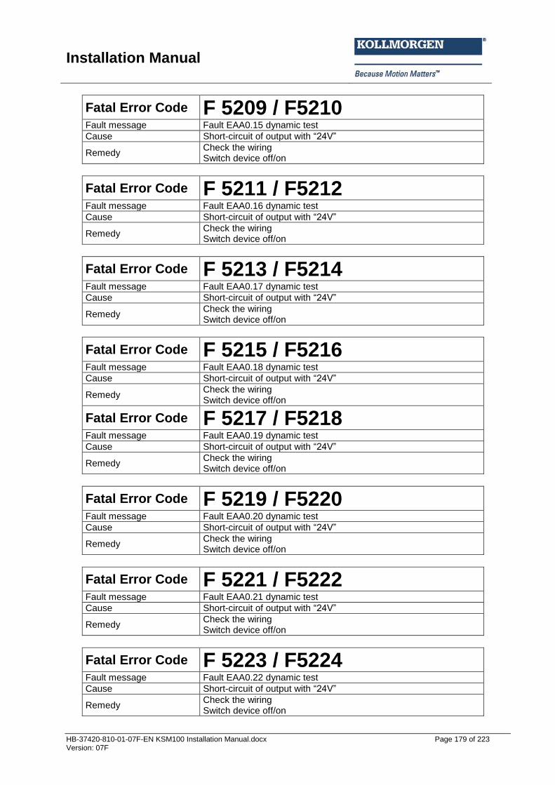
Installation Manual
HB-37420-810-01-07F-EN KSM100 Installation Manual.docx Page 179 of 223 Version: 07F
Fatal Error Code F 5209 / F5210 Fault message Fault EAA0.15 dynamic test
Cause Short-circuit of output with “24V”
Remedy Check the wiring Switch device off/on
Fatal Error Code F 5211 / F5212 Fault message Fault EAA0.16 dynamic test
Cause Short-circuit of output with “24V”
Remedy Check the wiring Switch device off/on
Fatal Error Code F 5213 / F5214 Fault message Fault EAA0.17 dynamic test
Cause Short-circuit of output with “24V”
Remedy Check the wiring Switch device off/on
Fatal Error Code F 5215 / F5216 Fault message Fault EAA0.18 dynamic test
Cause Short-circuit of output with “24V”
Remedy Check the wiring Switch device off/on
Fatal Error Code F 5217 / F5218 Fault message Fault EAA0.19 dynamic test
Cause Short-circuit of output with “24V”
Remedy Check the wiring Switch device off/on
Fatal Error Code F 5219 / F5220 Fault message Fault EAA0.20 dynamic test
Cause Short-circuit of output with “24V”
Remedy Check the wiring Switch device off/on
Fatal Error Code F 5221 / F5222 Fault message Fault EAA0.21 dynamic test
Cause Short-circuit of output with “24V”
Remedy Check the wiring Switch device off/on
Fatal Error Code F 5223 / F5224 Fault message Fault EAA0.22 dynamic test
Cause Short-circuit of output with “24V”
Remedy Check the wiring Switch device off/on
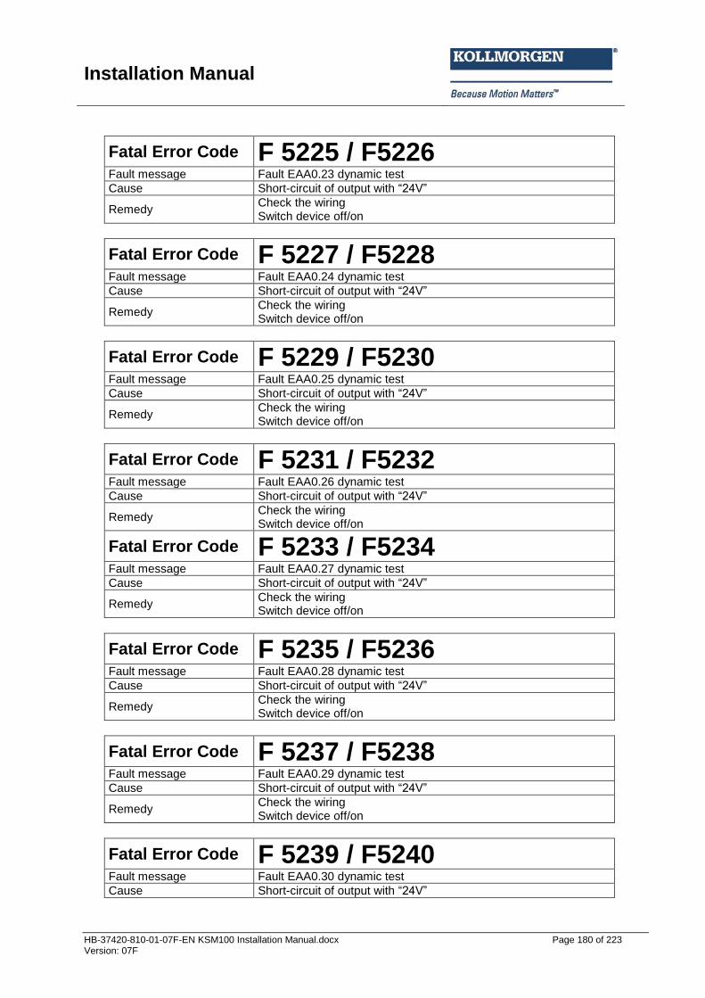
Installation Manual
HB-37420-810-01-07F-EN KSM100 Installation Manual.docx Page 180 of 223 Version: 07F
Fatal Error Code F 5225 / F5226 Fault message Fault EAA0.23 dynamic test
Cause Short-circuit of output with “24V”
Remedy Check the wiring Switch device off/on
Fatal Error Code F 5227 / F5228 Fault message Fault EAA0.24 dynamic test
Cause Short-circuit of output with “24V”
Remedy Check the wiring Switch device off/on
Fatal Error Code F 5229 / F5230 Fault message Fault EAA0.25 dynamic test
Cause Short-circuit of output with “24V”
Remedy Check the wiring Switch device off/on
Fatal Error Code F 5231 / F5232 Fault message Fault EAA0.26 dynamic test
Cause Short-circuit of output with “24V”
Remedy Check the wiring Switch device off/on
Fatal Error Code F 5233 / F5234 Fault message Fault EAA0.27 dynamic test
Cause Short-circuit of output with “24V”
Remedy Check the wiring Switch device off/on
Fatal Error Code F 5235 / F5236 Fault message Fault EAA0.28 dynamic test
Cause Short-circuit of output with “24V”
Remedy Check the wiring Switch device off/on
Fatal Error Code F 5237 / F5238 Fault message Fault EAA0.29 dynamic test
Cause Short-circuit of output with “24V”
Remedy Check the wiring Switch device off/on
Fatal Error Code F 5239 / F5240 Fault message Fault EAA0.30 dynamic test
Cause Short-circuit of output with “24V”
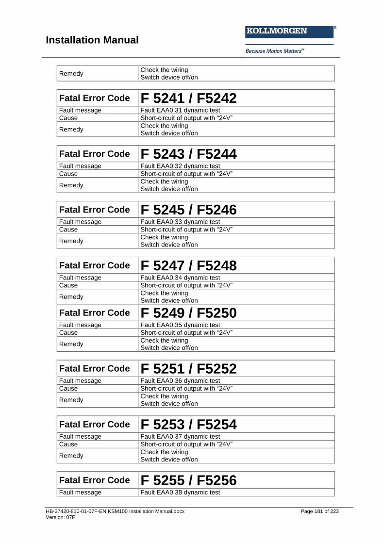
Installation Manual
HB-37420-810-01-07F-EN KSM100 Installation Manual.docx Page 181 of 223 Version: 07F
Remedy Check the wiring Switch device off/on
Fatal Error Code F 5241 / F5242 Fault message Fault EAA0.31 dynamic test
Cause Short-circuit of output with “24V”
Remedy Check the wiring Switch device off/on
Fatal Error Code F 5243 / F5244 Fault message Fault EAA0.32 dynamic test
Cause Short-circuit of output with “24V”
Remedy Check the wiring Switch device off/on
Fatal Error Code F 5245 / F5246 Fault message Fault EAA0.33 dynamic test
Cause Short-circuit of output with “24V”
Remedy Check the wiring Switch device off/on
Fatal Error Code F 5247 / F5248 Fault message Fault EAA0.34 dynamic test
Cause Short-circuit of output with “24V”
Remedy Check the wiring Switch device off/on
Fatal Error Code F 5249 / F5250 Fault message Fault EAA0.35 dynamic test
Cause Short-circuit of output with “24V”
Remedy Check the wiring Switch device off/on
Fatal Error Code F 5251 / F5252 Fault message Fault EAA0.36 dynamic test
Cause Short-circuit of output with “24V”
Remedy Check the wiring Switch device off/on
Fatal Error Code F 5253 / F5254 Fault message Fault EAA0.37 dynamic test
Cause Short-circuit of output with “24V”
Remedy Check the wiring Switch device off/on
Fatal Error Code F 5255 / F5256 Fault message Fault EAA0.38 dynamic test
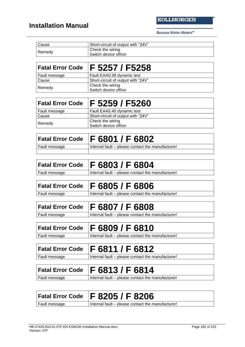
Installation Manual
HB-37420-810-01-07F-EN KSM100 Installation Manual.docx Page 182 of 223 Version: 07F
Cause Short-circuit of output with “24V”
Remedy Check the wiring Switch device off/on
Fatal Error Code F 5257 / F5258 Fault message Fault EAA0.39 dynamic test
Cause Short-circuit of output with “24V”
Remedy Check the wiring Switch device off/on
Fatal Error Code F 5259 / F5260 Fault message Fault EAA0.40 dynamic test
Cause Short-circuit of output with “24V”
Remedy Check the wiring Switch device off/on
Fatal Error Code F 6801 / F 6802 Fault message Internal fault – please contact the manufacturer!
Fatal Error Code F 6803 / F 6804 Fault message Internal fault – please contact the manufacturer!
Fatal Error Code F 6805 / F 6806 Fault message Internal fault – please contact the manufacturer!
Fatal Error Code F 6807 / F 6808 Fault message Internal fault – please contact the manufacturer!
Fatal Error Code F 6809 / F 6810 Fault message Internal fault – please contact the manufacturer!
Fatal Error Code F 6811 / F 6812 Fault message Internal fault – please contact the manufacturer!
Fatal Error Code F 6813 / F 6814 Fault message Internal fault – please contact the manufacturer!
Fatal Error Code F 8205 / F 8206 Fault message Internal fault – please contact the manufacturer!
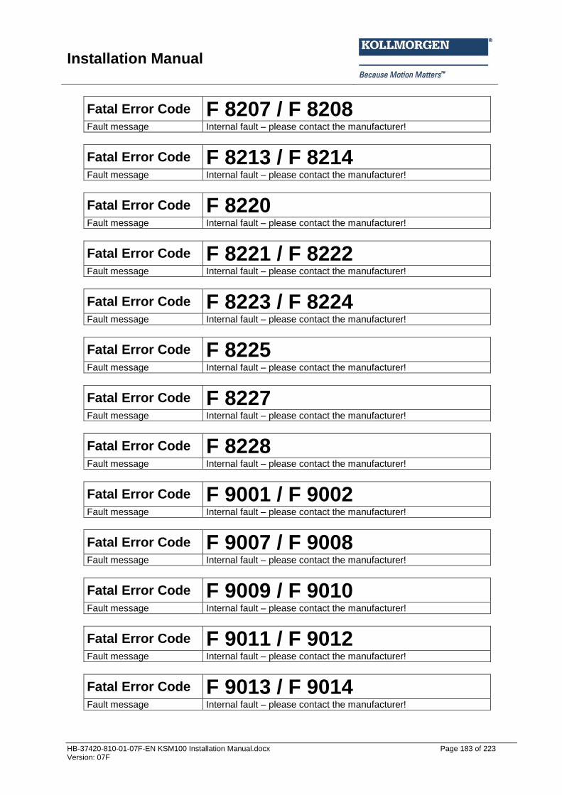
Installation Manual
HB-37420-810-01-07F-EN KSM100 Installation Manual.docx Page 183 of 223 Version: 07F
Fatal Error Code F 8207 / F 8208 Fault message Internal fault – please contact the manufacturer!
Fatal Error Code F 8213 / F 8214 Fault message Internal fault – please contact the manufacturer!
Fatal Error Code F 8220 Fault message Internal fault – please contact the manufacturer!
Fatal Error Code F 8221 / F 8222 Fault message Internal fault – please contact the manufacturer!
Fatal Error Code F 8223 / F 8224 Fault message Internal fault – please contact the manufacturer!
Fatal Error Code F 8225 Fault message Internal fault – please contact the manufacturer!
Fatal Error Code F 8227 Fault message Internal fault – please contact the manufacturer!
Fatal Error Code F 8228 Fault message Internal fault – please contact the manufacturer!
Fatal Error Code F 9001 / F 9002 Fault message Internal fault – please contact the manufacturer!
Fatal Error Code F 9007 / F 9008 Fault message Internal fault – please contact the manufacturer!
Fatal Error Code F 9009 / F 9010 Fault message Internal fault – please contact the manufacturer!
Fatal Error Code F 9011 / F 9012 Fault message Internal fault – please contact the manufacturer!
Fatal Error Code F 9013 / F 9014 Fault message Internal fault – please contact the manufacturer!

Installation Manual
HB-37420-810-01-07F-EN KSM100 Installation Manual.docx Page 184 of 223 Version: 07F
Fatal Error Code F 9015 / F 9016 Fault message Internal fault – please contact the manufacturer!
Fatal Error Code F 9017 / F 9018 Fault message Internal fault – please contact the manufacturer!
Fatal Error Code F 9051 Fault message Internal fault – please contact the manufacturer!
Fatal Error Code F 9101 / F 9102 Fault message SDDC signature fault
Cause Configuration fault bus communication
Remedy Switch device off/on
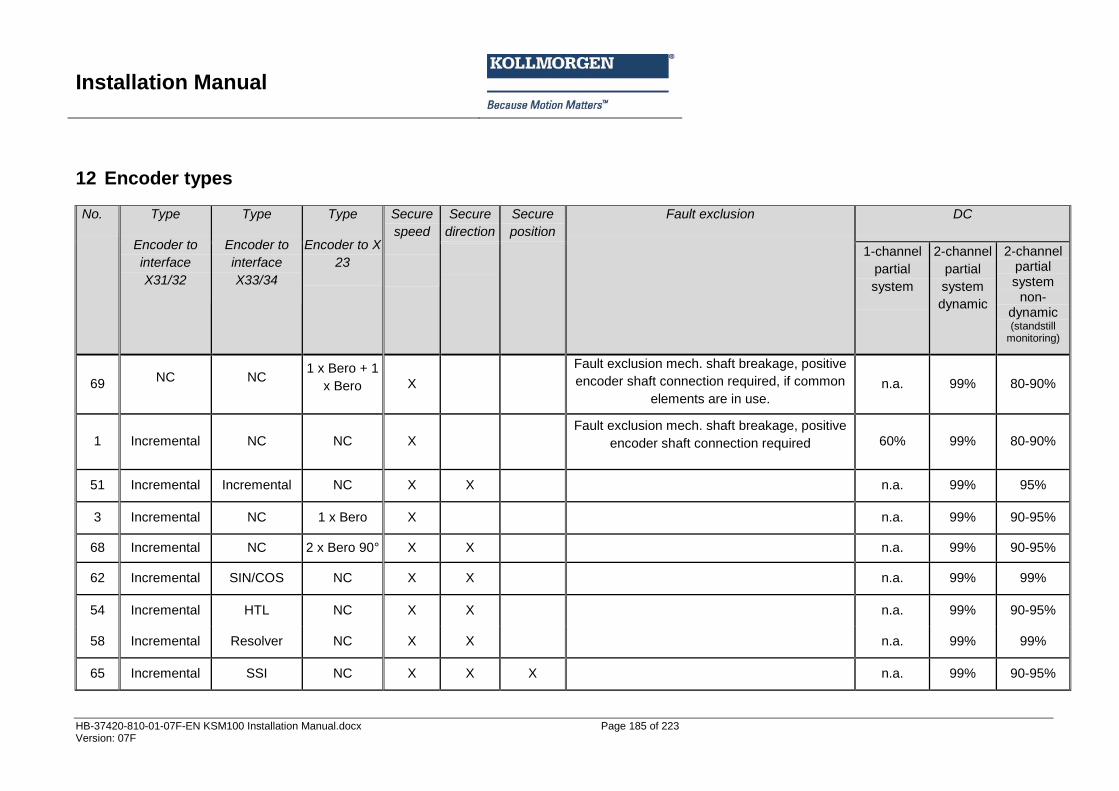
Installation Manual
HB-37420-810-01-07F-EN KSM100 Installation Manual.docx Page 185 of 223 Version: 07F
12 Encoder types No. Type
Encoder to
interface
X31/32
Type
Encoder to
interface
X33/34
Type
Encoder to X
23
Secure
speed
Secure
direction
Secure
position
Fault exclusion DC
1-channel
partial
system
2-channel
partial
system
dynamic
2-channel partial system
non-dynamic (standstill
monitoring)
69 NC NC
1 x Bero + 1
x Bero X
Fault exclusion mech. shaft breakage, positive
encoder shaft connection required, if common
elements are in use. n.a. 99% 80-90%
1 Incremental NC NC X
Fault exclusion mech. shaft breakage, positive
encoder shaft connection required 60% 99% 80-90%
51 Incremental Incremental NC X X
n.a. 99% 95%
3 Incremental NC 1 x Bero X
n.a. 99% 90-95%
68 Incremental NC 2 x Bero 90° X X
n.a. 99% 90-95%
62 Incremental SIN/COS NC X X
n.a. 99% 99%
54 Incremental HTL NC X X
n.a. 99% 90-95%
58 Incremental Resolver NC X X
n.a. 99% 99%
65 Incremental SSI NC X X X
n.a. 99% 90-95%
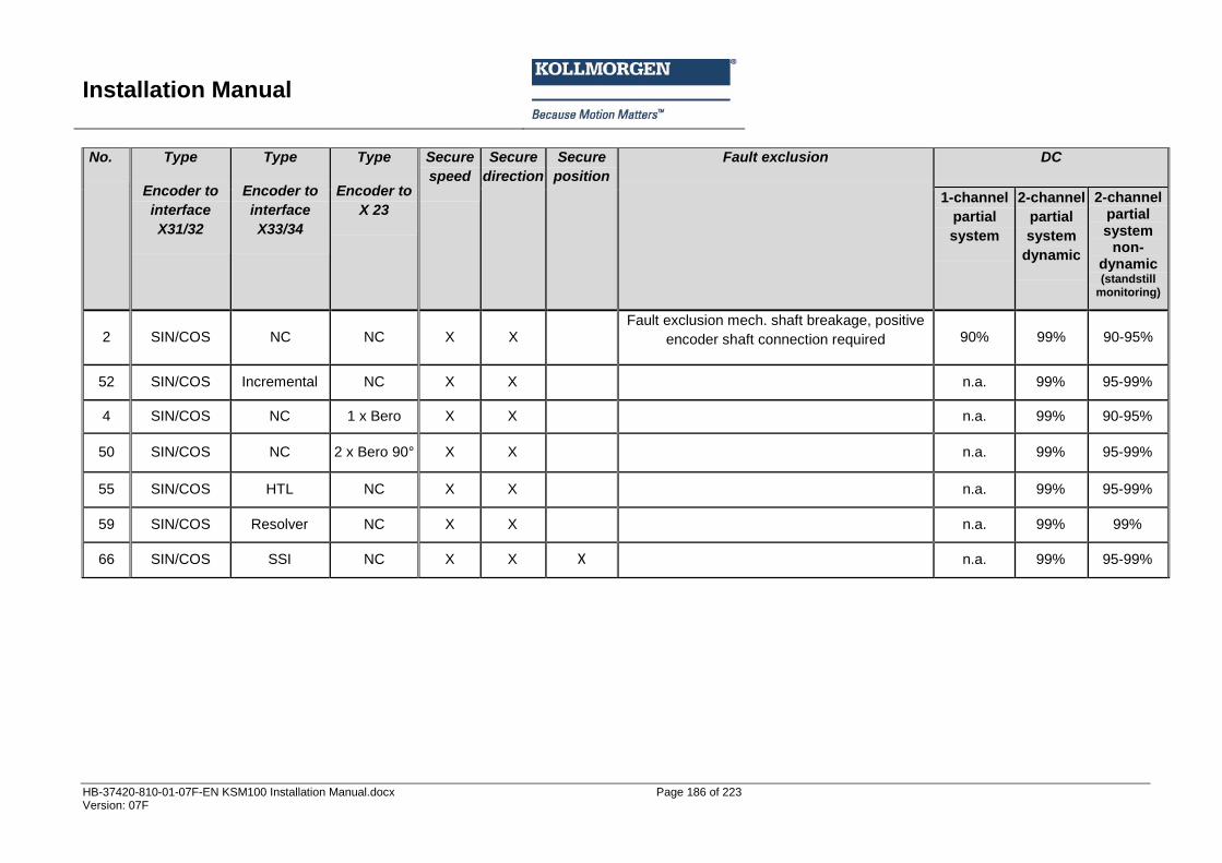
Installation Manual
HB-37420-810-01-07F-EN KSM100 Installation Manual.docx Page 186 of 223 Version: 07F
No. Type
Encoder to
interface
X31/32
Type
Encoder to
interface
X33/34
Type
Encoder to
X 23
Secure
speed
Secure
direction
Secure
position
Fault exclusion DC
1-channel
partial
system
2-channel
partial
system
dynamic
2-channel partial system
non-dynamic (standstill
monitoring)
2 SIN/COS NC NC X X
Fault exclusion mech. shaft breakage, positive
encoder shaft connection required 90% 99% 90-95%
52 SIN/COS Incremental NC X X
n.a. 99% 95-99%
4 SIN/COS NC 1 x Bero X X
n.a. 99% 90-95%
50 SIN/COS NC 2 x Bero 90° X X
n.a. 99% 95-99%
55 SIN/COS HTL NC X X
n.a. 99% 95-99%
59 SIN/COS Resolver NC X X
n.a. 99% 99%
66 SIN/COS SSI NC X X X n.a. 99% 95-99%
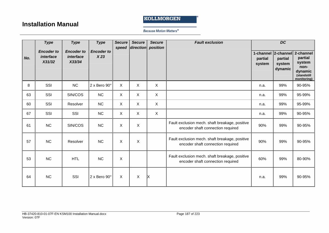
Installation Manual
HB-37420-810-01-07F-EN KSM100 Installation Manual.docx Page 187 of 223 Version: 07F
No.
Type
Encoder to
interface
X31/32
Type
Encoder to
interface
X33/34
Type
Encoder to
X 23
Secure
speed
Secure
direction
Secure
position
Fault exclusion DC
1-channel
partial
system
2-channel
partial
system
dynamic
2-channel partial system
non-dynamic (standstill
monitoring)
8 SSI NC 2 x Bero 90° X X X
n.a. 99% 90-95%
63 SSI SIN/COS NC X X X
n.a. 99% 95-99%
60 SSI Resolver NC X X X
n.a. 99% 95-99%
67 SSI SSI NC X X X
n.a. 99% 90-95%
61 NC SIN/COS NC X X
Fault exclusion mech. shaft breakage, positive
encoder shaft connection required 90% 99% 90-95%
57 NC Resolver NC X X
Fault exclusion mech. shaft breakage, positive
encoder shaft connection required 90% 99% 90-95%
53 NC HTL NC X
Fault exclusion mech. shaft breakage, positive
encoder shaft connection required 60% 99% 80-90%
64 NC SSI 2 x Bero 90° X X X
n.a. 99% 90-95%
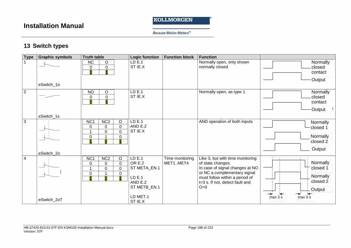
Installation Manual
HB-37420-810-01-07F-EN KSM100 Installation Manual.docx Page 188 of 223 Version: 07F
13 Switch types Type Graphic symbols Truth table Logic function Function block Function
1
eSwitch_1o
NC O
0 0
1 1
LD E.1 ST IE.X
Normally open, only shown normally closed Öffner
Ausgang
2
sSwitch_1s
NO O
0 0
1 1
LD E.1 ST IE.X
Normally open, as type 1 Öffner
Ausgang
3
eSwitch_2o
NC1 NC2 O
0 0 0
1 0 0
0 1 0
1 1 1
LD E.1 AND E.2 ST IE.X
AND operation of both inputs
Öffner 2
Ausgang
Öffner 1
4
t
eSwitch_2oT
NC1 NC2 O
0 0 0
1 0 0
0 1 0
1 1 1
LD E.1 OR E.2 ST META_EN.1 LD E.1 AND E.2 ST METB_EN.1 LD MET.1 ST IE.X
Time monitoring MET1..MET4
Like 3, but with time monitoring of state changes. In case of signal changes at NO or NC a complementary signal must follow within a period of t=3 s. If not, detect fault and O=0
Öffner 2
Ausgang
Öffner 1
max. 3 s max. 3 s
Normally closed contact
Output
Normally closed contact
Output
Normally closed 2
Normally closed 1
Output
Normally closed 2
Normally closed 1
Output
max 3 s max 3 s
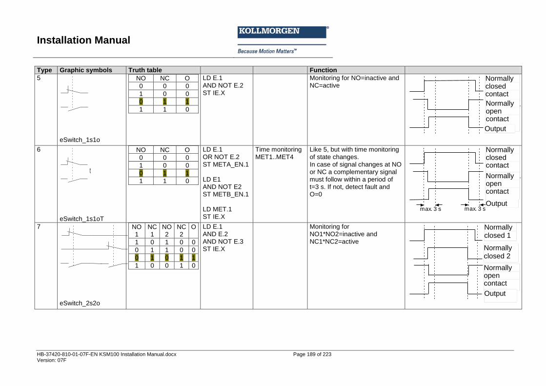
Installation Manual
HB-37420-810-01-07F-EN KSM100 Installation Manual.docx Page 189 of 223 Version: 07F
Type Graphic symbols Truth table Function
5
eSwitch_1s1o
NO NC O
0 0 0
1 0 0
0 1 1
1 1 0
LD E.1 AND NOT E.2 ST IE.X
Monitoring for NO=inactive and NC=active
Schließer
Ausgang
Öffner
6
t
eSwitch_1s1oT
NO NC O
0 0 0
1 0 0
0 1 1
1 1 0
LD E.1 OR NOT E.2 ST META_EN.1 LD E1 AND NOT E2 ST METB_EN.1 LD MET.1 ST IE.X
Time monitoring MET1..MET4
Like 5, but with time monitoring of state changes. In case of signal changes at NO or NC a complementary signal must follow within a period of t=3 s. If not, detect fault and O=0
Schließer
Ausgang
Öffner
max. 3 s max. 3 s
7
eSwitch_2s2o
NO1
NC1
NO2
NC2
O
1 0 1 0 0
0 1 1 0 0
0 1 0 1 1
1 0 0 1 0
LD E.1 AND E.2 AND NOT E.3 ST IE.X
Monitoring for NO1*NO2=inactive and NC1*NC2=active
Schließer
Öffner 2
Ausgang
Öffner 1
Normally closed contact
Normally open contact
Output
Normally closed contact
Output
Normally open contact
Normally closed 2
Normally closed 1
Normally open contact
Output
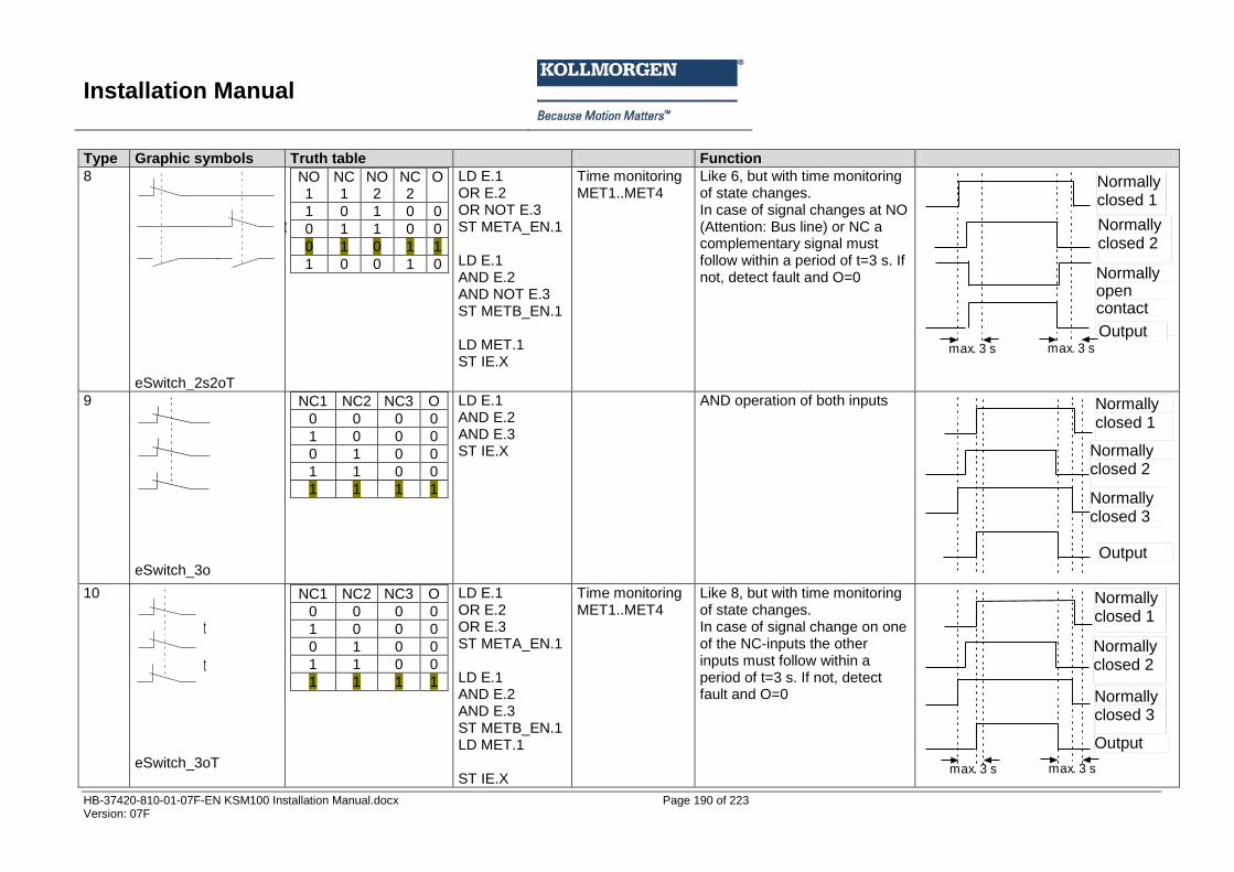
Installation Manual
HB-37420-810-01-07F-EN KSM100 Installation Manual.docx Page 190 of 223 Version: 07F
Type Graphic symbols Truth table Function
8
t
eSwitch_2s2oT
NO1
NC1
NO2
NC2
O
1 0 1 0 0
0 1 1 0 0
0 1 0 1 1
1 0 0 1 0
LD E.1 OR E.2 OR NOT E.3 ST META_EN.1 LD E.1 AND E.2 AND NOT E.3 ST METB_EN.1 LD MET.1 ST IE.X
Time monitoring MET1..MET4
Like 6, but with time monitoring of state changes. In case of signal changes at NO (Attention: Bus line) or NC a complementary signal must follow within a period of t=3 s. If not, detect fault and O=0 Schließer
Öffner 2
Ausgang
Öffner 1
max. 3 s max. 3 s
9
eSwitch_3o
NC1 NC2 NC3 O
0 0 0 0
1 0 0 0
0 1 0 0
1 1 0 0
1 1 1 1
LD E.1 AND E.2 AND E.3 ST IE.X
AND operation of both inputs
Öffner 2
Ausgang
Öffner 1
Öffner 3
10
t
t
eSwitch_3oT
NC1 NC2 NC3 O
0 0 0 0
1 0 0 0
0 1 0 0
1 1 0 0
1 1 1 1
LD E.1 OR E.2 OR E.3 ST META_EN.1 LD E.1 AND E.2 AND E.3 ST METB_EN.1 LD MET.1 ST IE.X
Time monitoring MET1..MET4
Like 8, but with time monitoring of state changes. In case of signal change on one of the NC-inputs the other inputs must follow within a period of t=3 s. If not, detect fault and O=0
Öffner 2
Ausgang
Öffner 1
max. 3 s max. 3 s
Öffner 3
Normally closed 2
Normally open contact
Normally closed 1
Output
Normally closed 1
Normally closed 2
Output
Normally closed 3
Normally closed 1
Normally closed 2
Output
Normally closed 3
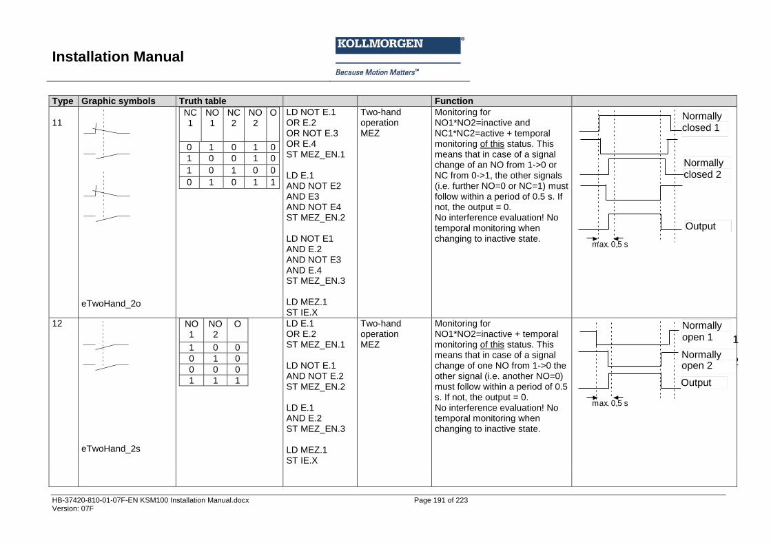
Installation Manual
HB-37420-810-01-07F-EN KSM100 Installation Manual.docx Page 191 of 223 Version: 07F
Type Graphic symbols Truth table Function
11
eTwoHand_2o
NC1
NO1
NC2
NO2
O
0 1 0 1 0
1 0 0 1 0
1 0 1 0 0
0 1 0 1 1
LD NOT E.1 OR E.2 OR NOT E.3 OR E.4 ST MEZ_EN.1 LD E.1 AND NOT E2 AND E3 AND NOT E4 ST MEZ_EN.2 LD NOT E1 AND E.2 AND NOT E3 AND E.4 ST MEZ_EN.3 LD MEZ.1 ST IE.X
Two-hand operation MEZ
Monitoring for NO1*NO2=inactive and NC1*NC2=active + temporal monitoring of this status. This means that in case of a signal change of an NO from 1->0 or NC from 0->1, the other signals (i.e. further NO=0 or NC=1) must follow within a period of 0.5 s. If not, the output = 0. No interference evaluation! No temporal monitoring when changing to inactive state.
Öffner 2
Ausgang
Öffner 1
max. 0,5 s
12
eTwoHand_2s
NO1
NO2
O
1 0 0
0 1 0
0 0 0
1 1 1
LD E.1 OR E.2 ST MEZ_EN.1 LD NOT E.1 AND NOT E.2 ST MEZ_EN.2 LD E.1 AND E.2 ST MEZ_EN.3 LD MEZ.1 ST IE.X
Two-hand operation MEZ
Monitoring for NO1*NO2=inactive + temporal monitoring of this status. This means that in case of a signal change of one NO from 1->0 the other signal (i.e. another NO=0) must follow within a period of 0.5 s. If not, the output = 0. No interference evaluation! No temporal monitoring when changing to inactive state.
Ausgang
Schließer 1
max. 0,5 s
Schließer 2
Normally closed 1
Normally closed 2
Output
Normally open 1
Normally open 2
Output
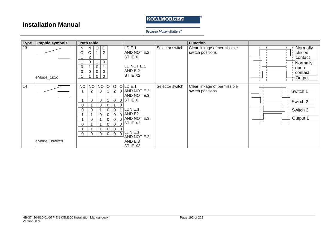
Installation Manual
HB-37420-810-01-07F-EN KSM100 Installation Manual.docx Page 192 of 223 Version: 07F
Type Graphic symbols Truth table Function
13
eMode_1s1o
NO1
NO2
O1
O2
1 0 1 0
0 1 0 1
0 0 0 0
1 1 0 0
LD E.1 AND NOT E.2 ST IE.X LD NOT E.1 AND E.2 ST IE.X2
Selector switch Clear linkage of permissible switch positions
Schließer
Ausgang
Öffner
14
eMode_3switch
NO1
NO2
NO3
O1
O2
O3
1 0 0 1 0 0
0 1 0 0 1 0
0 0 1 0 0 1
1 1 0 0 0 0
1 0 1 0 0 0
0 1 1 0 0 0
1 1 1 0 0 0
0 0 0 0 0 0
LD E.1 AND NOT E.2 AND NOT E.3 ST IE.X LDN E.1 AND E2 AND NOT E.3 ST IE.X2 LDN E.1 AND NOT E.2 AND E.3 ST IE.X3
Selector switch Clear linkage of permissible switch positions
Schalter 2
Ausgang 1
Schalter 1
Schalter 3
Output
Normally open contact
Normally closed contact
Switch 1
Output 1
Switch 2
Switch 3
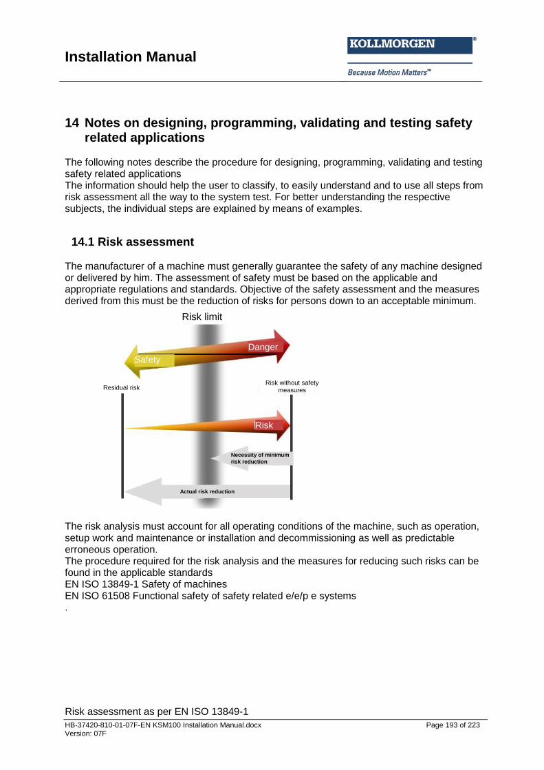
Installation Manual
HB-37420-810-01-07F-EN KSM100 Installation Manual.docx Page 193 of 223 Version: 07F
14 Notes on designing, programming, validating and testing safety related applications
The following notes describe the procedure for designing, programming, validating and testing safety related applications The information should help the user to classify, to easily understand and to use all steps from risk assessment all the way to the system test. For better understanding the respective subjects, the individual steps are explained by means of examples.
14.1 Risk assessment The manufacturer of a machine must generally guarantee the safety of any machine designed or delivered by him. The assessment of safety must be based on the applicable and appropriate regulations and standards. Objective of the safety assessment and the measures derived from this must be the reduction of risks for persons down to an acceptable minimum.
The risk analysis must account for all operating conditions of the machine, such as operation, setup work and maintenance or installation and decommissioning as well as predictable erroneous operation. The procedure required for the risk analysis and the measures for reducing such risks can be found in the applicable standards EN ISO 13849-1 Safety of machines EN ISO 61508 Functional safety of safety related e/e/p e systems . Risk assessment as per EN ISO 13849-1
Actual risk reduction
Necessity of minimum
risk reduction
Danger
Risk limit
Risk
Residual risk
Safety
Risk without safety measures
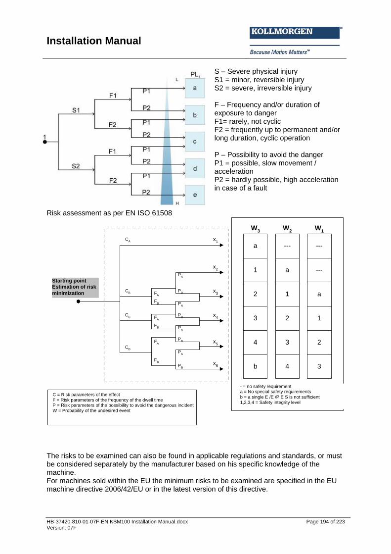
Installation Manual
HB-37420-810-01-07F-EN KSM100 Installation Manual.docx Page 194 of 223 Version: 07F
S – Severe physical injury S1 = minor, reversible injury S2 = severe, irreversible injury F – Frequency and/or duration of exposure to danger F1= rarely, not cyclic F2 = frequently up to permanent and/or long duration, cyclic operation P – Possibility to avoid the danger P1 = possible, slow movement / acceleration P2 = hardly possible, high acceleration in case of a fault
Risk assessment as per EN ISO 61508
a
1
2
3
4
b
W3
---
a
1
2
3
4
W2
---
---
a
1
2
3
W1
--- = keine Sicherheitsanforderung
a = Keine speziellen Sicherheitsanforderungen
b = eine einzelnes E/E/PES ist nicht ausreichend
1,2,3,4 = Sicherheits-Integritätslevel
CA
CB
CC
CD
FA
FB
PA
PB
FA
FB
FA
FB
PA
PB
PA
PB
PA
PB
x1
x2
x4
x3
x5
x6
Startpunkt
Abschätzung der
Risikominderung
C = Risikoparameter der Auswirkung
F = Risikoparameter der Häufigkeit und Aufenthaltsdauer
P = Risikoparameter der Möglichkeit, den gefährlichen Vorfall
zu vermeiden
W = Wahrscheinlichkeit des unerwünschten Ereignisses
The risks to be examined can also be found in applicable regulations and standards, or must be considered separately by the manufacturer based on his specific knowledge of the machine. For machines sold within the EU the minimum risks to be examined are specified in the EU machine directive 2006/42/EU or in the latest version of this directive.
Starting point Estimation of risk
minimization
C = Risk parameters of the effect F = Risk parameters of the frequency of the dwell time P = Risk parameters of the possibility to avoid the dangerous incident W = Probability of the undesired event
- = no safety requirement a = No special safety requirements b = a single E /E /P E S is not sufficient 1,2,3,4 = Safety integrity level

Installation Manual
HB-37420-810-01-07F-EN KSM100 Installation Manual.docx Page 195 of 223 Version: 07F
Further information concerning the risk assessment and the safe design of machines can be found in the standards EN 14121 Safety of machines - risk assessment EN 12100 Safety of machines - basic terms, general design guidelines . Measures to be applied in order to reduce identified risks must at least be of the same level as the danger itself. The regulations and standards specified above contain examples of such measures and the associated requirements.
14.2 Required technical documents The manufacturer is obliged to supply various technical documents. The minimum extent is also contained in the applicable regulations and standards. The EU machine directive, for example, requires the delivery of the following documents:
Source BGIA Report 2/2008 The documents must be easy to understand and should be written in the language of the corresponding country.
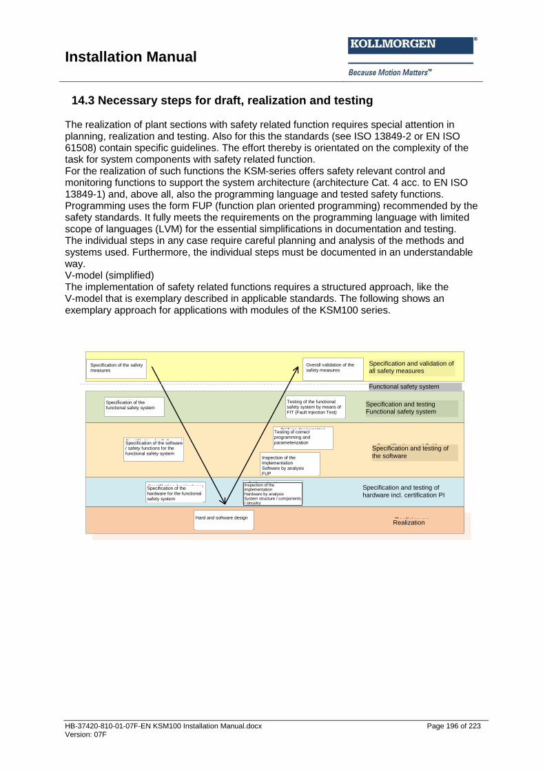
Installation Manual
HB-37420-810-01-07F-EN KSM100 Installation Manual.docx Page 196 of 223 Version: 07F
14.3 Necessary steps for draft, realization and testing The realization of plant sections with safety related function requires special attention in planning, realization and testing. Also for this the standards (see ISO 13849-2 or EN ISO 61508) contain specific guidelines. The effort thereby is orientated on the complexity of the task for system components with safety related function. For the realization of such functions the KSM-series offers safety relevant control and monitoring functions to support the system architecture (architecture Cat. 4 acc. to EN ISO 13849-1) and, above all, also the programming language and tested safety functions. Programming uses the form FUP (function plan oriented programming) recommended by the safety standards. It fully meets the requirements on the programming language with limited scope of languages (LVM) for the essential simplifications in documentation and testing. The individual steps in any case require careful planning and analysis of the methods and systems used. Furthermore, the individual steps must be documented in an understandable way. V-model (simplified) The implementation of safety related functions requires a structured approach, like the V-model that is exemplary described in applicable standards. The following shows an exemplary approach for applications with modules of the KSM100 series.
Spezifikation der
Sicherheitsmaßnahmen
Spezifikation des
funktionalen
Sicherheitssystems
Spezifikation der Hardware
für das funktionale
Sicherheitssystem
Spezifikation der Software /
Sicherheitsfunktionen für
das funktionale
Sicherheitssystem
Hard- und Softwaredesign
Prüfung der Umsetzung
Hardware durch Analyse
Anlagenaufbau /
Komponenten /Schaltung
Prüfung der Umsetzung
Software durch Analyse
FUP
Prüfung der korrekten
Programmierung und
Parametrierung durch
Analyse Validierungsreport
Prüfung des funktionalen
Sicherheitssystems durch
FIT (Fault Injection Test)
Gesamtvalidierung der
Sicherheitsmaßnahmen
Funktionales Sicherheitssystem
Spezifikation und Prüfung
Funktionales Sicherheitssystem
Spezifikation und Prüfung
der Software
Spezifikation und Prüfung
der Hardware incl. Nachweis Pl
Realisierung
Spezifikation und Validierung
aller Sicherheitsmaßnahmen
Specification of the safety measures
Specification of the functional safety system
Testing of the functional safety system by means of FIT (Fault Injection Test)
Overall validation of the safety measures
Specification of the software / safety functions for the functional safety system
Specification of the hardware for the functional safety system
Hard and software design
Inspection of the implementation Hardware by analysis System structure / components / circuitry
Testing of correct programming and parameterization
Inspection of the implementation Software by analysis FUP
Specification and validation of all safety measures
Specification and testing of
the software
Specification and testing Functional safety system
Specification and testing of
hardware incl. certification PI
Realization
Functional safety system

Installation Manual
HB-37420-810-01-07F-EN KSM100 Installation Manual.docx Page 197 of 223 Version: 07F
Phases of the V-model:
Designation Description Design phase Validation phase Specification and validation of all safety measures
Specification of all applicable passive or active safety measures to be applied, such as covers, barriers, max. machine parameters, safety related functions, etc.
Testing of all passive and active safety measures for correct implementation and effectiveness.
Specification of the functional safety systems
Specification of the active safety systems and their assignment to the risks to be reduced, such as e.g. reduced speed in setup operation, stop-mode, monitoring of access areas, etc. Specification of the PIr or the demanded SIL for each individual safety function
Testing of all active safety systems regarding effectiveness and compliance with specific parameters, such as e.g. erroneous increased speed, faulty stop, responding of monitoring facilities, etc. by means of practical tests
Specification of software / safety functions
Specification of the functionality of individual safety functions incl. the definition of the shut-down circuit, etc. Definition of parameters for individual safety functions, such as e.g. max. speed, stop ramps and - categories, etc.
Examination of the correct implementation of functional specifications by analysing the FUP-programming Validation of the application program and the parameters by comparing the validation report with FUP or the specifications for parameters
Specification of the hardware
Specification of the system structure and the functions of the individual sensors, command units, control components and actuators regarding their safety functions
Testing of the correct implementation of specifications. Determination of the failure probability or PI by means of analysis of the overall architecture and the characteristic data of all components involved, each related to the individual safety functions
Hard and software design
Actual planning and implementation of system structure / wiring. Actual implementation of safety functions by programming in FUP
Nil

Installation Manual
HB-37420-810-01-07F-EN KSM100 Installation Manual.docx Page 198 of 223 Version: 07F
14.3.1 Specification of safety requirements (structural schematic) The safety requirements must be individually analysed on the basis of applicable standards, e.g. product standard.

Installation Manual
HB-37420-810-01-07F-EN KSM100 Installation Manual.docx Page 199 of 223 Version: 07F
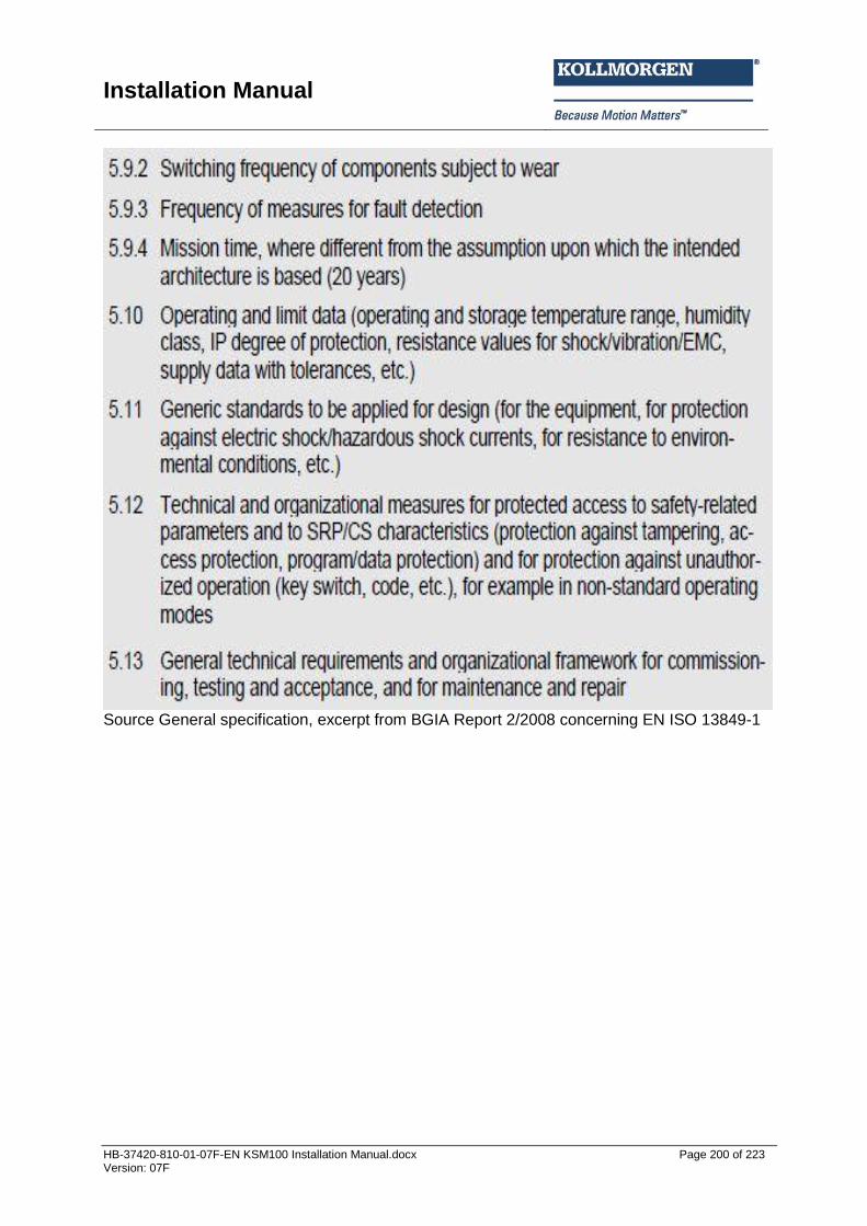
Installation Manual
HB-37420-810-01-07F-EN KSM100 Installation Manual.docx Page 200 of 223 Version: 07F
Source General specification, excerpt from BGIA Report 2/2008 concerning EN ISO 13849-1

Installation Manual
HB-37420-810-01-07F-EN KSM100 Installation Manual.docx Page 201 of 223 Version: 07F
Example for an automatic handling machine: Description of function: The automatic handling machine serves the purpose of automatically picking up truck cabins of different heights. After being picked up, the height of the cabin is correctly detected, so that within the working area the cabin cannot be lowered below a certain height. Within the working area the automatic machine must not exceed a maximum speed. Once the cabin has been completely finished, it is put down at the end of the processing line and the automatic handling machine moves along a return track back to the beginning of the track to pick up the next cabin. Limits of the machine: Spatial limits: The working area must provide sufficient space for the workers, so that they are able to carry out all necessary work on the cabin..... In the return pass there must be sufficient space for the empty suspension gear of the automatic handler... Temporal limits: Description of lifetime, description of ageing processes, which could cause changes of machine parameters, (e.g. brakes). Monitoring mechanisms must be implemented for such cases. Limits of use: The automatic machine automatically fetches new cabins and moves these through a processing area. Workers work in the processing area .... etc. The following operating modes are intended: Setup operation, automatic operation and service operation ... etc. Identification of dangers: The following dangers are of relevance with the automatic handling machine: Danger 1: Crushing by cabin / lifting beam falling down Danger 2: Impact by moving cabin / lifting beam Danger 3: Crushing by too fast lowering of the cabin in case of a fault Danger 4:.............. Risk analysis: G1: The weight of cabin and lifting beam is so high, that it will cause irreversible crushing or even fatalities. G2: The moving cabin/lifting beam may cause impacts that can lead to irreversible injuries. G3: …. Risk assessment A risk reduction is required under due consideration of all operating conditions. Inherently (risk from the project) safe design Movement of the cabin in direction x and y within the working area cannot be avoided. In the processing area the cabin must be moved up/down ... The following measures can be applied: Avoid dangers caused by too fast movements Avoid dangers caused by too small distances
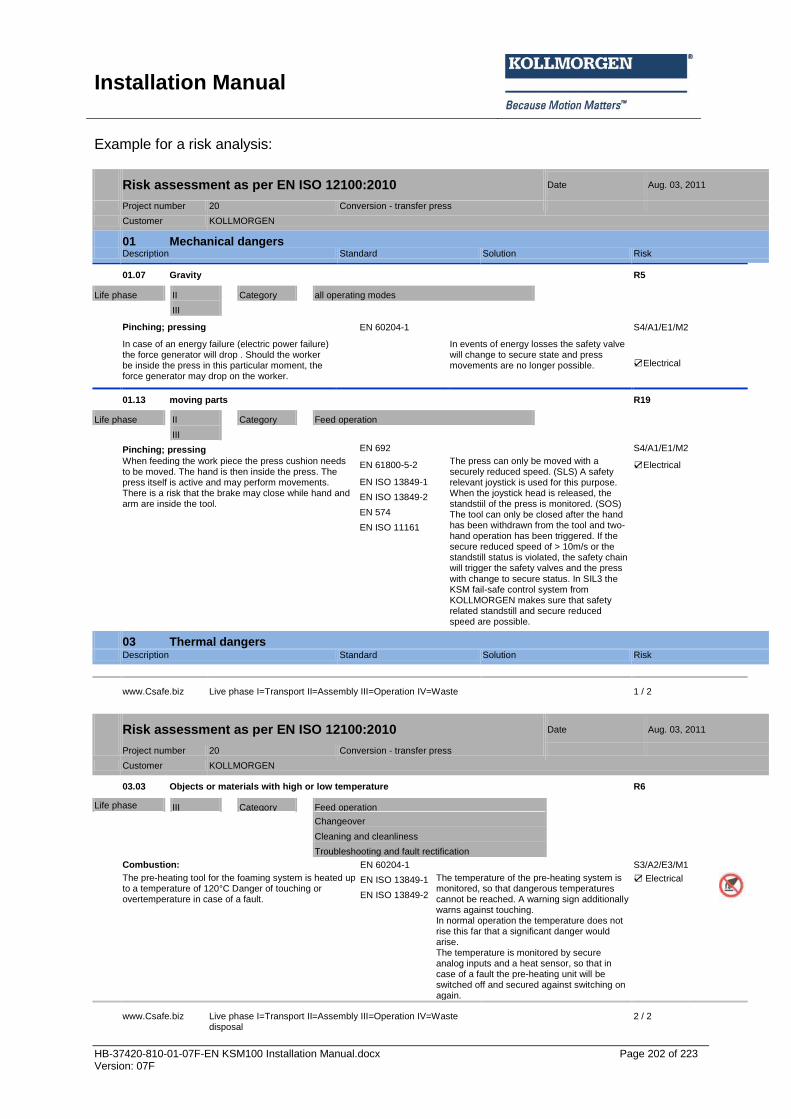
Installation Manual
HB-37420-810-01-07F-EN KSM100 Installation Manual.docx Page 202 of 223 Version: 07F
Example for a risk analysis:
Risk assessment as per EN ISO 12100:2010 Date Aug. 03, 2011
Project number 20 Conversion - transfer press
Customer KOLLMORGEN
01 Mechanical dangers Description Standard Solution Risk
01.07 Gravity R5
Life phase II Category all operating modes
III
Pinching; pressing EN 60204-1 S4/A1/E1/M2
In case of an energy failure (electric power failure) the force generator will drop . Should the worker be inside the press in this particular moment, the force generator may drop on the worker.
In events of energy losses the safety valve will change to secure state and press movements are no longer possible. Electrical
01.13 moving parts R19
Life phase II Category Feed operation
III
Pinching; pressing EN 692 S4/A1/E1/M2
When feeding the work piece the press cushion needs to be moved. The hand is then inside the press. The press itself is active and may perform movements. There is a risk that the brake may close while hand and arm are inside the tool.
EN 61800-5-2 The press can only be moved with a securely reduced speed. (SLS) A safety relevant joystick is used for this purpose. When the joystick head is released, the standstiil of the press is monitored. (SOS) The tool can only be closed after the hand has been withdrawn from the tool and two-hand operation has been triggered. If the secure reduced speed of > 10m/s or the standstill status is violated, the safety chain will trigger the safety valves and the press with change to secure status. In SIL3 the KSM fail-safe control system from KOLLMORGEN makes sure that safety related standstill and secure reduced speed are possible.
Electrical
EN ISO 13849-1
EN ISO 13849-2
EN 574
EN ISO 11161
03 Thermal dangers Description Standard Solution Risk
www.Csafe.biz Live phase I=Transport II=Assembly III=Operation IV=Waste disposal
1 / 2
Risk assessment as per EN ISO 12100:2010 Date Aug. 03, 2011
Project number 20 Conversion - transfer press
Customer KOLLMORGEN
03.03 Objects or materials with high or low temperature R6
Life phase III Category Feed operation
Changeover
Cleaning and cleanliness
Troubleshooting and fault rectification
Combustion: EN 60204-1 S3/A2/E3/M1
The pre-heating tool for the foaming system is heated up to a temperature of 120°C Danger of touching or overtemperature in case of a fault.
EN ISO 13849-1 The temperature of the pre-heating system is monitored, so that dangerous temperatures cannot be reached. A warning sign additionally warns against touching. In normal operation the temperature does not rise this far that a significant danger would arise. The temperature is monitored by secure analog inputs and a heat sensor, so that in case of a fault the pre-heating unit will be switched off and secured against switching on again.
Electrical
EN ISO 13849-2
www.Csafe.biz Live phase I=Transport II=Assembly III=Operation IV=Waste disposal
2 / 2
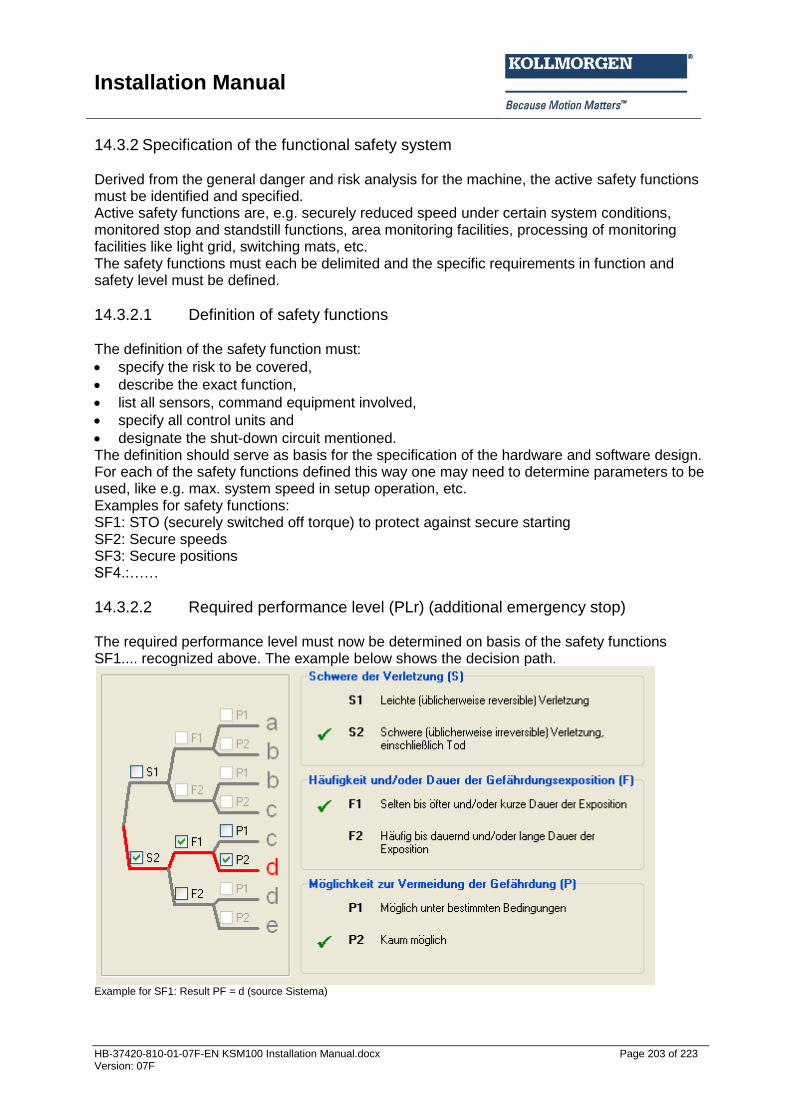
Installation Manual
HB-37420-810-01-07F-EN KSM100 Installation Manual.docx Page 203 of 223 Version: 07F
14.3.2 Specification of the functional safety system Derived from the general danger and risk analysis for the machine, the active safety functions must be identified and specified. Active safety functions are, e.g. securely reduced speed under certain system conditions, monitored stop and standstill functions, area monitoring facilities, processing of monitoring facilities like light grid, switching mats, etc. The safety functions must each be delimited and the specific requirements in function and safety level must be defined.
14.3.2.1 Definition of safety functions The definition of the safety function must:
specify the risk to be covered,
describe the exact function,
list all sensors, command equipment involved,
specify all control units and
designate the shut-down circuit mentioned. The definition should serve as basis for the specification of the hardware and software design. For each of the safety functions defined this way one may need to determine parameters to be used, like e.g. max. system speed in setup operation, etc. Examples for safety functions: SF1: STO (securely switched off torque) to protect against secure starting SF2: Secure speeds SF3: Secure positions SF4.:……
14.3.2.2 Required performance level (PLr) (additional emergency stop) The required performance level must now be determined on basis of the safety functions SF1.... recognized above. The example below shows the decision path.
Example for SF1: Result PF = d (source Sistema)
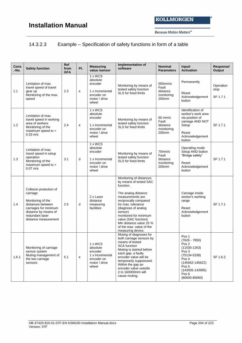
Installation Manual
HB-37420-810-01-07F-EN KSM100 Installation Manual.docx Page 204 of 223 Version: 07F
14.3.2.3 Example – Specification of safety functions in form of a table
Cons.-No.
Safety function Ref from GFA
Plr Measuring value /sensor
Implementation of software
Nominal Parameters
Input/ Activation
Response/ Output
1.1
Limitation of max. travel speed of travel gear up Monitoring of the max. speed
2.3 e
1 x WCS absolute encoder 1 x Incremental encoder on motor / drive wheel
Monitoring by means of tested safety function SLS for fixed limits
550mm/s Fault distance monitoring 200mm
Permanently Reset: Acknowledgement button
Operation stop SF 1.7.1
1.2
Limitation of max. travel speed in working area of workers Monitoring of the maximum speed to < 0.33 m/s
2.4 e
1 x WCS absolute encoder 1 x Incremental encoder on motor / drive wheel
Monitoring by means of tested safety function SLS for fixed limits
60 mm/s Fault distance monitoring 200mm
Identification of worker's work area via position of carriage AND NOT Setup Reset: Acknowledgement button
SF 1.7.1
1.3
Limitation of max. travel speed in setup operation Monitoring of the maximum speed to < 0.07 m/s
3.1 d
1 x WCS absolute encoder 1 x Incremental encoder on motor / drive wheel
Monitoring by means of tested safety function SLS for fixed limits
70mm/s Fault distance monitoring 200mm
Operating mode Setup AND button “Bridge safet ” Reset: Acknowledgement button
SF 1.7.1
1.4
Collision protection of carriage Monitoring of the distances between carriages for minimum distance by means of redundant laser distance measurement
2.5 d
2 x Laser distance measuring facilities
Monitoring of distances by means of tested SAC function. The analog distance measurements are reciprocally compared for max. tolerance (diagnose of analog sensor) monitored for minimum value (SAC function) Min distance value 25 % of the max. value of the measuring device.
Carriage inside worker's working range Reset: Acknowledgement button
SF 1.7.1
1.6.1
Monitoring of carriage sensor system Muting management of the two carriage sensors
5.1 e
1 x WCS absolute encoder 1 x Incremental encoder on motor / drive wheel
Muting of diagnoses for both carriage sensors by means of tested SCA function Muting is started before each gap, a faulty encoder value will be temporarily suppressed. Within the gap an encoder value outside 2 to 160000mm will cause muting.
Pos 1 (7626 - 7850) Pos 2 (11030-1263) Pos 3 (75134-5338) Pos 4 (145562-145622) Pos 5 (143935-143995) Pos 6 (80000-80060)
SF 1.6.2

Installation Manual
HB-37420-810-01-07F-EN KSM100 Installation Manual.docx Page 205 of 223 Version: 07F
14.3.3 Software specification The software specification refers to the previous specification of the safety functions. It can also be replaced by a correspondingly worked out specification of the safety functions, as far as this contains all specifications (see example under 14.3.2.3). However, it is recommended to prepare an extracted list. This list should contain the following data:
Designation of safety function
Description of function
Parameters, as far as available
Triggering event / operating status
Response / output
The specification in detail should be suitable for later validation of the programming.
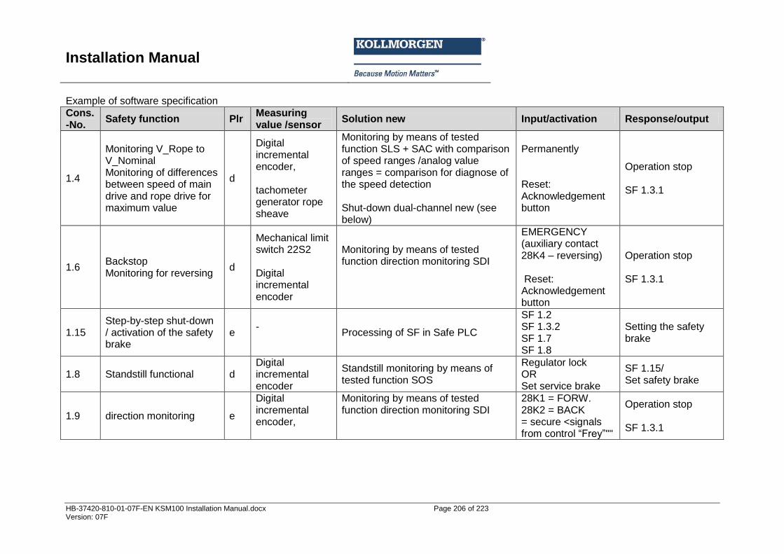
Installation Manual
HB-37420-810-01-07F-EN KSM100 Installation Manual.docx Page 206 of 223 Version: 07F
Example of software specification
Cons.-No.
Safety function Plr Measuring value /sensor
Solution new Input/activation Response/output
1.4
Monitoring V_Rope to V_Nominal Monitoring of differences between speed of main drive and rope drive for maximum value
d
Digital incremental encoder, tachometer generator rope sheave
Monitoring by means of tested function SLS + SAC with comparison of speed ranges /analog value ranges = comparison for diagnose of the speed detection Shut-down dual-channel new (see below)
Permanently Reset: Acknowledgement button
Operation stop SF 1.3.1
1.6 Backstop Monitoring for reversing
d
Mechanical limit switch 22S2 Digital incremental encoder
Monitoring by means of tested function direction monitoring SDI
EMERGENCY (auxiliary contact 28K4 – reversing) Reset: Acknowledgement button
Operation stop SF 1.3.1
1.15 Step-by-step shut-down / activation of the safety brake
e -
Processing of SF in Safe PLC
SF 1.2 SF 1.3.2 SF 1.7 SF 1.8
Setting the safety brake
1.8 Standstill functional d Digital incremental encoder
Standstill monitoring by means of tested function SOS
Regulator lock OR Set service brake
SF 1.15/ Set safety brake
1.9 direction monitoring e
Digital incremental encoder,
Monitoring by means of tested function direction monitoring SDI
28K1 = FORW. 28K2 = BACK = secure <signals from control “Fre ”""
Operation stop SF 1.3.1

Installation Manual
HB-37420-810-01-07F-EN KSM100 Installation Manual.docx Page 207 of 223 Version: 07F
14.3.4 Hardware specification The hardware specification should describe the entire system design and, in particular, the components used with their specific characteristic data. The hardware specification serves as basis for the determination of the achieved safety level based on the architecture and the characteristic data of all devices involved in a safety function. Furthermore, the hardware specification should also specify the design measures applied for protecting against systematic and common cause faults.
14.3.4.1 Selection of SRP/CS and operating means The selection of SRP/CS (Safety related parts of control system) is most suitable to achieve the intended safety level and should be made for any safety function. The components with safety relevant function must be designated in a total overview of the system structure and are to be assigned to the individual safety functions The safety related code numbers must be determined for these components. The code numbers cover the following values: MTTFD = mean time to failure, the mean time until a danger imposing failure DC avg = diagnostic covering (in average), the mean diagnostic coverage CCF = common cause failure, a failure caused on a common cause For an SRP/CS both the software and systematic faults must be taken into consideration. An analysis of of the SRP/CS participating in the safety function must generally be performed in accordance with the schematic Sensor / PES / Actuator.
Sensor PES AktuatorActuator
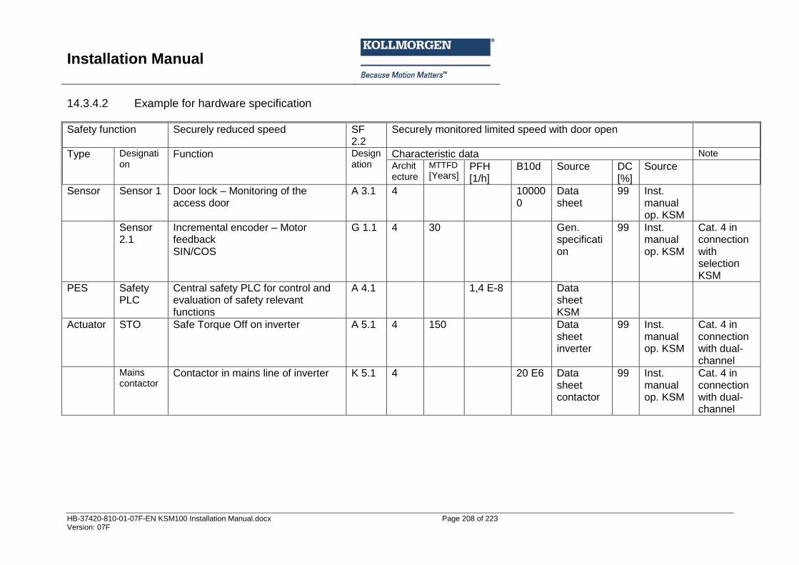
Installation Manual
HB-37420-810-01-07F-EN KSM100 Installation Manual.docx Page 208 of 223 Version: 07F
14.3.4.2 Example for hardware specification
Safety function
Securely reduced speed SF 2.2
Securely monitored limited speed with door open
Type Designation
Function Designation
Characteristic data Note
Architecture
MTTFD
[Years] PFH [1/h]
B10d Source DC [%]
Source
Sensor Sensor 1 Door lock – Monitoring of the access door
A 3.1 4 100000
Data sheet
99 Inst. manual op. KSM
Sensor 2.1
Incremental encoder – Motor feedback SIN/COS
G 1.1 4 30 Gen. specification
99 Inst. manual op. KSM
Cat. 4 in connection with selection KSM
PES Safety PLC
Central safety PLC for control and evaluation of safety relevant functions
A 4.1 1,4 E-8 Data sheet KSM
Actuator STO Safe Torque Off on inverter A 5.1 4 150 Data sheet inverter
99 Inst. manual op. KSM
Cat. 4 in connection with dual-channel
Mains contactor
Contactor in mains line of inverter K 5.1 4 20 E6 Data sheet contactor
99 Inst. manual op. KSM
Cat. 4 in connection with dual-channel
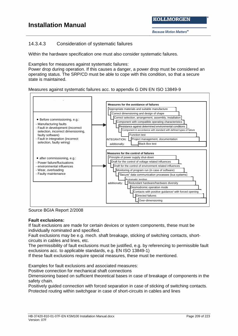
Installation Manual
HB-37420-810-01-07F-EN KSM100 Installation Manual.docx Page 209 of 223 Version: 07F
14.3.4.3 Consideration of systematic failures Within the hardware specification one must also consider systematic failures. Examples for measures against systematic failures: Power drop during operation. If this causes a danger, a power drop must be considered an operating status. The SRP/CD must be able to cope with this condition, so that a secure state is maintained. Measures against systematic failures acc. to appendix G DIN EN ISO 13849-9
Source BGIA Report 2/2008 Fault exclusions: If fault exclusions are made for certain devices or system components, these must be individually nominated and specified. Fault exclusions may be e.g. mech. shaft breakage, sticking of switching contacts, short-circuits in cables and lines, etc. The permissibility of fault exclusions must be justified, e.g. by referencing to permissible fault exclusions acc. to applicable standards, e.g. EN ISO 13849-1) If these fault exclusions require special measures, these must be mentioned. Examples for fault exclusions and associated measures: Positive connection for mechanical shaft connections Dimensioning based on sufficient theoretical bases in case of breakage of components in the safety chain. Positively guided connection with forced separation in case of sticking of switching contacts. Protected routing within switchgear in case of short-circuits in cables and lines
Before commissioning, e.g.:
- Manufacturing faults - Fault in development (incorrect
selection, incorrect dimensioning, faulty software)
- Fault in integration (incorrect selection, faulty wiring)
after commissioning, e.g.:
- Power failure/fluctuations - environmental influences - Wear, overloading - Faulty maintenance
Measures for the avoidance of failures
Black-Box test
Automatic testing
Redundant hardware/hardware diversity
Desmodromic operation mode
Contacts with positive guidance/ with forced opening
Directed failures
Over-dimensioning
Draft for the control of environment related influences
Draft for the control of voltage related influences
Principle of power supply shut-down
additionally:
“Secure” data communication processes (bus s stems)
Monitoring of program run (in case of software)
Correct selection, arrangement, assembly, installation
Correct dimensioning and design of shape
Appropriate materials and suitable manufacture
Function test
Project management, documentation
Component in accordance with standard with defined types of failure
Resistance against determined environmental conditions
Component with compatible operating characteristics
INTEGRATION:
additionally:
Measures for the control of failures

Installation Manual
HB-37420-810-01-07F-EN KSM100 Installation Manual.docx Page 210 of 223 Version: 07F
14.3.5 Hard and software design The performance targets from the hardware and software specification are implemented in the actual system design. The performance targets for the components to be used and their wiring from the hardware specification must also be met, the same applies for the performance targets for fault exclusions. Both must be achieved and documented with appropriate means. In the software one must also account for and completely implement the targets from the software specification. Furthermore one must consider the superimposed targets placed on the software by safety related programming. These are among others: Modular and clear program structure Assignment of functions to the safety functions Understandable representation functions by: Unambiguous designations Understandable comments Use of tested functions / function modules, as far as this is possible Defensive programming
14.3.6 Testing of the hardware design After completing the planning the hardware design must be examined for compliance with the targets from the hardware specification. Furthermore, one must check the compliance with the specified safety level for each safety function by using suitable analyses. The analysis methods have been described in applicable standards (e.g. EN 13849-1). Analysis of wiring diagram Compliance with the targets set under safety related aspects can be checked by means of the wiring diagram and the bill of materials. The following must be checked in particular: the correct wiring of components as specified, the dual-channel structure, as far as specified the non-reactivity of parallel, redundant channels. The use of components as specified The checks should be made by understandable analysis.
14.3.6.1 Iterative testing of the achieved safety level The achieved safety level must be determined by means of the circuit structure (= architecture single-channel (dual-channel / with or without diagnose), the characteristic device data (manufacturer's data or appropriate sources) and the diagnostic coverage (manufacturer's data PES or general sources). Appropriate measures can be taken from the underlying safety standard.
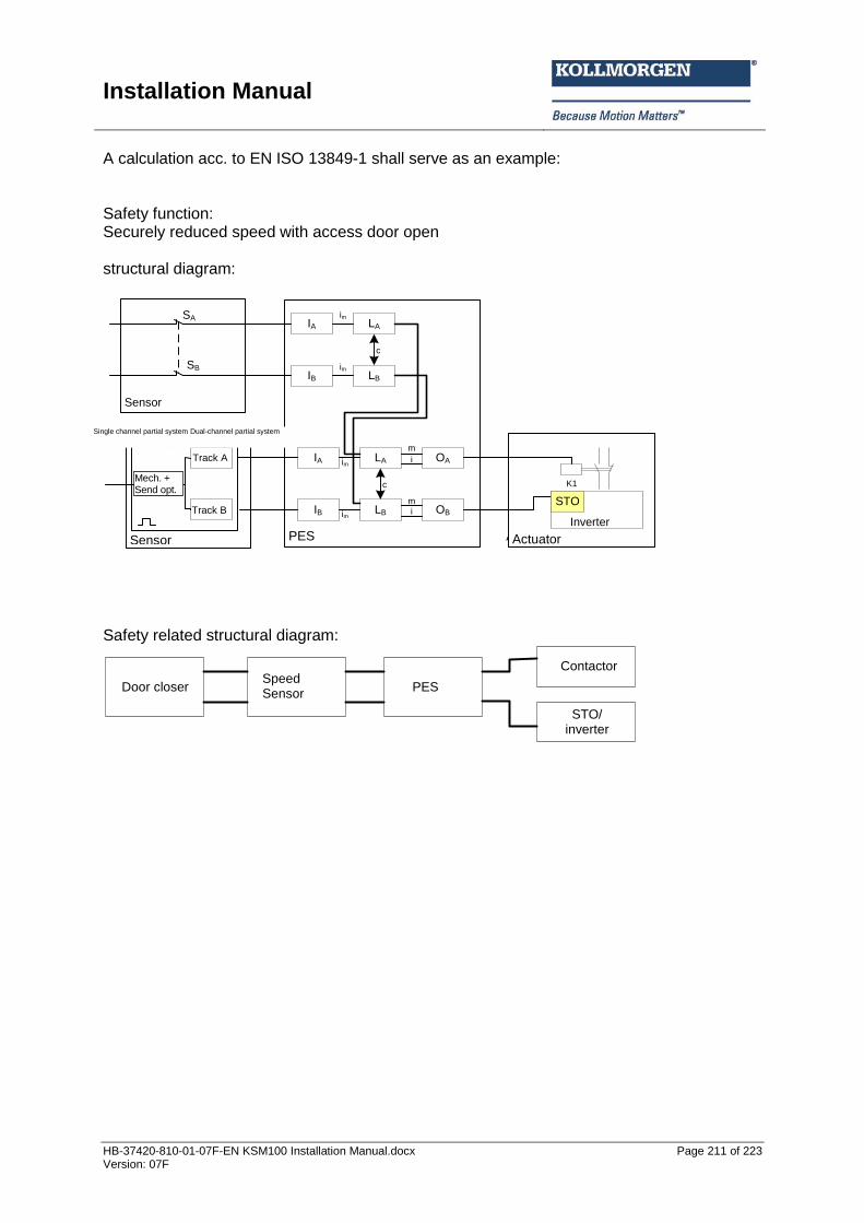
Installation Manual
HB-37420-810-01-07F-EN KSM100 Installation Manual.docx Page 211 of 223 Version: 07F
A calculation acc. to EN ISO 13849-1 shall serve as an example: Safety function: Securely reduced speed with access door open structural diagram:
IA LA
IB LB
c
im
im
Sensor
SA
SB
IA OALA
IB OBLB
m
m
i
i
c
im
im
Sensor PES Aktuator
Eink. Teilsyst.
Mech.+
Sendeopt.
Spur A
Spur B
Zweik. Teilsyst.
Aktuator
K1
Umrichter
STO
Safety related structural diagram:
TürzuhaltungGeschw.
SensorPES
Schütz
STO/
Umrichter
Sensor
Track B
Track A
Single channel partial system Dual-channel partial system
PES Actuator
Inverter
Mech. + Send opt.
PES Door closer Speed Sensor
STO/ inverter
Contactor
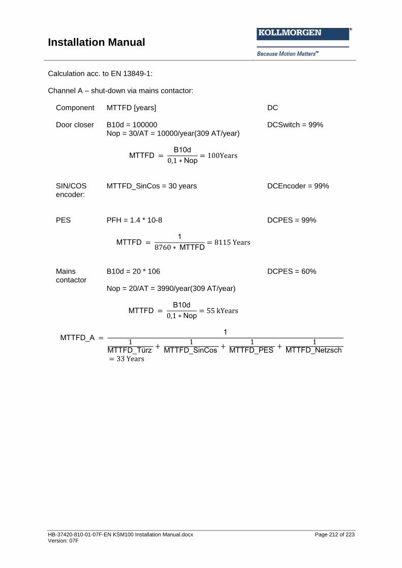
Installation Manual
HB-37420-810-01-07F-EN KSM100 Installation Manual.docx Page 212 of 223 Version: 07F
Calculation acc. to EN 13849-1: Channel A – shut-down via mains contactor: Component MTTFD [years] DC
Door closer B10d = 100000 Nop = 30/AT = 10000/year(309 AT/year)
MTTFD B10d
Nop
DCSwitch = 99%
SIN/COS encoder:
MTTFD_SinCos = 30 years
DCEncoder = 99%
PES
PFH = 1.4 * 10-8
MTTFD 1
MTTFD
DCPES = 99%
Mains contactor
B10d = 20 * 106 Nop = 20/AT = 3990/year(309 AT/year)
MTTFD B10d
Nop
DCPES = 60%
MTTFD A 1
MTTFD T r
MTTFD SinCos
MTTFD PES
MTTFD Net sch
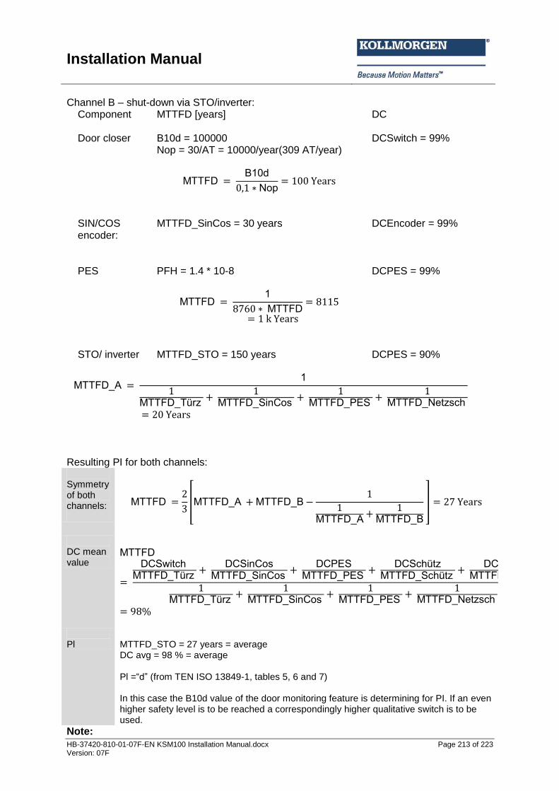
Installation Manual
HB-37420-810-01-07F-EN KSM100 Installation Manual.docx Page 213 of 223 Version: 07F
Channel B – shut-down via STO/inverter: Component MTTFD [years] DC
Door closer B10d = 100000 Nop = 30/AT = 10000/year(309 AT/year)
MTTFD B10d
Nop
DCSwitch = 99%
SIN/COS encoder:
MTTFD_SinCos = 30 years
DCEncoder = 99%
PES
PFH = 1.4 * 10-8
MTTFD 1
MTTFD
DCPES = 99%
STO/ inverter
MTTFD_STO = 150 years
DCPES = 90%
MTTFD A 1
MTTFD T r
MTTFD SinCos
MTTFD PES
MTTFD Net sch
Resulting PI for both channels: Symmetry of both channels:
MTTFD
[MTTFD A MTTFD B
MTTFD A
MTTFD B
]
DC mean value
MTTFD
DCS itch MTTFD T r
DCSinCos
MTTFD SinCos
DCPESMTTFD PES
DCSch t
MTTFD Sch t
DCSTOMTTFD STO
MTTFD T r
MTTFD SinCos
MTTFD PES
MTTFD Net sch
Pl
MTTFD_STO = 27 years = average DC avg = 98 % = average Pl =“d” (from TEN ISO 13849-1, tables 5, 6 and 7) In this case the B10d value of the door monitoring feature is determining for PI. If an even higher safety level is to be reached a correspondingly higher qualitative switch is to be used.
Note:
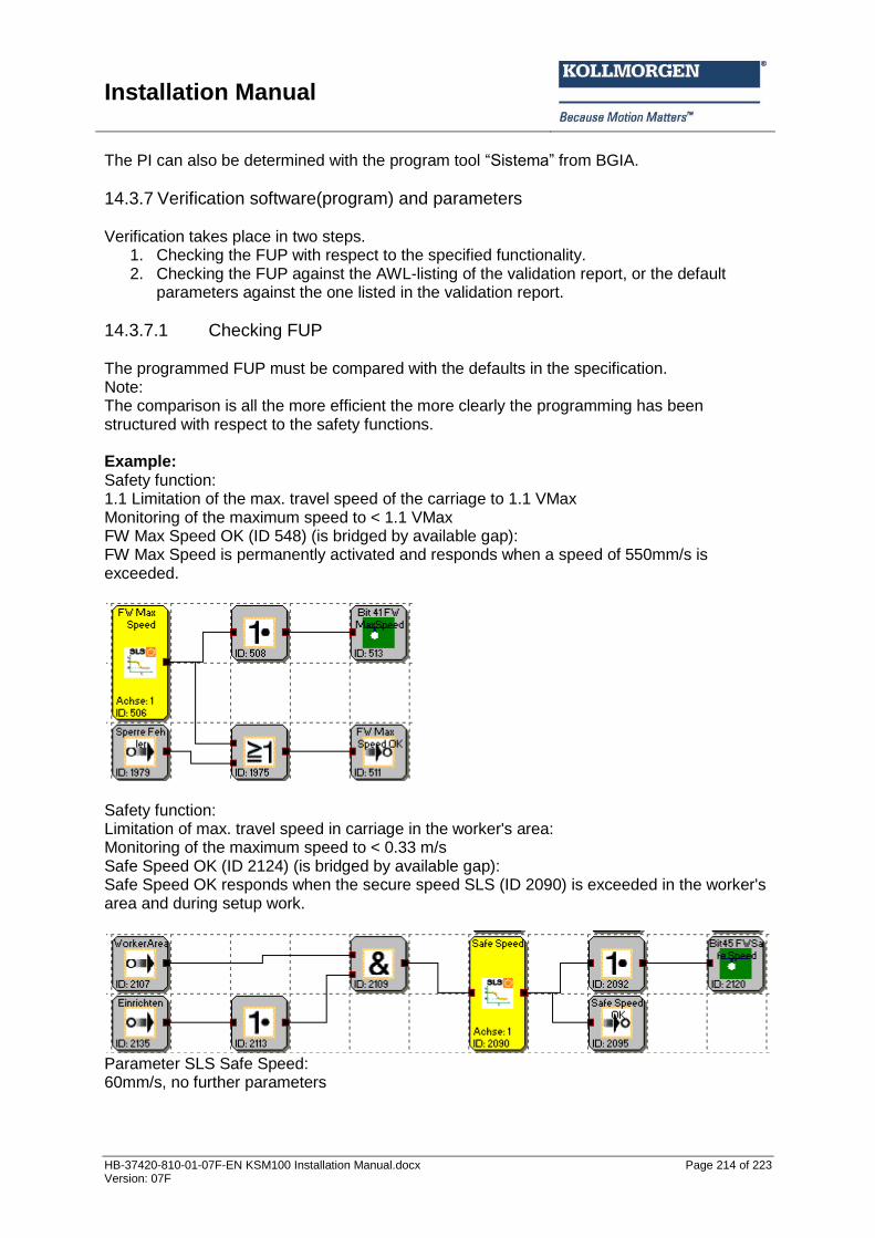
Installation Manual
HB-37420-810-01-07F-EN KSM100 Installation Manual.docx Page 214 of 223 Version: 07F
The PI can also be determined with the program tool “Sistema” from BGIA.
14.3.7 Verification software(program) and parameters Verification takes place in two steps.
1. Checking the FUP with respect to the specified functionality. 2. Checking the FUP against the AWL-listing of the validation report, or the default
parameters against the one listed in the validation report.
14.3.7.1 Checking FUP The programmed FUP must be compared with the defaults in the specification. Note: The comparison is all the more efficient the more clearly the programming has been structured with respect to the safety functions. Example: Safety function: 1.1 Limitation of the max. travel speed of the carriage to 1.1 VMax Monitoring of the maximum speed to < 1.1 VMax FW Max Speed OK (ID 548) (is bridged by available gap): FW Max Speed is permanently activated and responds when a speed of 550mm/s is exceeded.
Safety function: Limitation of max. travel speed in carriage in the worker's area: Monitoring of the maximum speed to < 0.33 m/s Safe Speed OK (ID 2124) (is bridged by available gap): Safe Speed OK responds when the secure speed SLS (ID 2090) is exceeded in the worker's area and during setup work.
Parameter SLS Safe Speed: 60mm/s, no further parameters
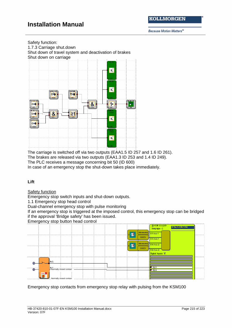
Installation Manual
HB-37420-810-01-07F-EN KSM100 Installation Manual.docx Page 215 of 223 Version: 07F
Safety function: 1.7.3 Carriage shut.down Shut down of travel system and deactivation of brakes Shut down on carriage
The carriage is switched off via two outputs (EAA1.5 ID 257 and 1.6 ID 261). The brakes are released via two outputs (EAA1.3 ID 253 and 1.4 ID 249). The PLC receives a message concerning bit 50 (ID 600) In case of an emergency stop the shut-down takes place immediately. Lift Safety function Emergency stop switch inputs and shut-down outputs. 1.1 Emergency stop head control Dual-channel emergency stop with pulse monitoring If an emergency stop is triggered at the imposed control, this emergency stop can be bridged if the approval 'Bridge safety' has been issued. Emergency stop button head control
Emergency stop contacts from emergency stop relay with pulsing from the KSM100
Normally closed contact
Normally closed contact
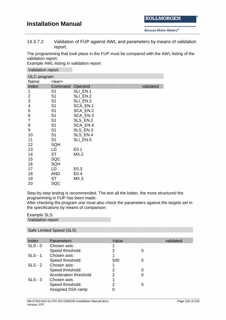
Installation Manual
HB-37420-810-01-07F-EN KSM100 Installation Manual.docx Page 216 of 223 Version: 07F
14.3.7.2 Validation of FUP against AWL and parameters by means of validation report.
The programming that took place in the FUP must be compared with the AWL-listing of the validation report. Example AWL-listing in validation report
Validation report
OLC-program Name: <leer>
Index Command Operand validated 1 S1 SLI_EN.1
2 S1 SLI_EN.2 3 S1 SLI_EN.3 4 S1 SCA_EN.1 5 S1 SCA_EN.2 6 S1 SCA_EN.3 7 S1 SLS_EN.2 8 S1 SCA_EN.4 9 S1 SLS_EN.3 10 S1 SLS_EN.4 11 S1 SLI_EN.5 12 SQH
13 LD E0.1 14 ST MX.2 15 SQC
16 SQH 17 LD E0.3
18 AND E0.4 19 ST MX.3 20 SQC
Step-by-step testing is recommended. The test all the batter, the more structured the programming in FUP has been made. After checking the program one must also check the parameters against the targets set in the specifications by means of comparison.
Example SLS: Validation report
Safe Limited Speed (SLS)
Index Parameters Value validated SLS - 0 Chosen axis: 1
Speed threshold: 2 0 SLS - 1 Chosen axis: 1
Speed threshold: 500 0 SLS - 2 Chosen axis: 1
Speed threshold: 2 0
Acceleration threshold 2 0
SLS - 3 Chosen axis: 1
Speed threshold: 2 0
Assigned SSX-ramp 0
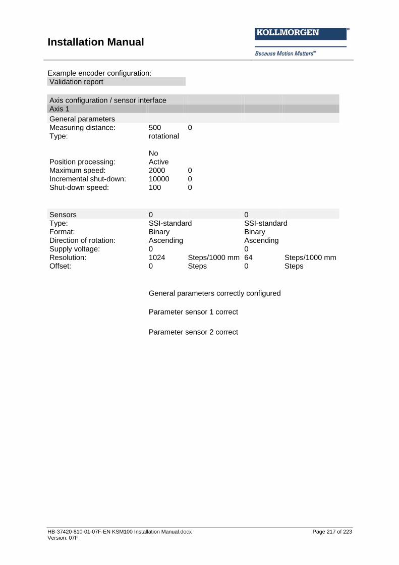
Installation Manual
HB-37420-810-01-07F-EN KSM100 Installation Manual.docx Page 217 of 223 Version: 07F
Example encoder configuration: Validation report
Axis configuration / sensor interface Axis 1
General parameters Measuring distance: 500 0
Type: rotational
No Position processing: Active Maximum speed: 2000 0
Incremental shut-down: 10000 0 Shut-down speed: 100 0
Sensors 0 0 Type: SSI-standard SSI-standard Format: Binary
Binary
Direction of rotation: Ascending
Ascending Supply voltage: 0
0
Resolution: 1024 Steps/1000 mm 64 Steps/1000 mm Offset: 0 Steps 0 Steps
General parameters correctly configured
Parameter sensor 1 correct
Parameter sensor 2 correct

Installation Manual
HB-37420-810-01-07F-EN KSM100 Installation Manual.docx Page 218 of 223 Version: 07F
14.3.8 Performance of the system test / FIT (fault injection test) For the FIT the manufacturer must prepare a complete list of the functions to be tested. This list includes the defined safety functions as well as the fault test for checking the right response of the SRP/CS to this fault Example test list: No Setup Test Result 1 Test SLS for max. speed in setup operation Activate setup operation
Travel with maximally allowed speed
- Diagnose of the actual speed versus the SLS limit - Manipulation of the setup speed beyond the permitted reduced speed
2 Test SSX for Stop-category 2 Travel with max. speed
Actuate the emergency stop
- Diagnose of the SSX-ramp against the actual deceleration ramp - Setting an impermissible weak deceleration - Moving the axis after standstill is reached by manipulating the drive
3 Test of the dual-channel door monitoring Select operating mode for
setup operation Diagnose of inactive monitoring with door closed (using diagnostics function FUP) Diagnose of active monitoring with door open (using diagnostics function FUP) Disconnecting one channel and opening the door Generate cross-shorting between both inputs

Installation Manual
HB-37420-810-01-07F-EN KSM100 Installation Manual.docx Page 219 of 223 Version: 07F
Appendix A
Classification of switch types
General note:
The individual switches of the following input elements can be assigned to the digital inputs DI1 to DI8 as desired.
Enable switch
Switch type Comment
Classification PI acc. to EN ISO 13849-1
Classification SIL acc. to EN 61508
1 normally closed Enable switch standard Pl d SIL 2
1 normally open Enable switch standard Pl d SIL 2 2 normally closed Enable switch higher
requirements Pl e SIL 3
2 normally closed time monitored
Enable switch monitored Pl e SIL 3
Emergency Stop
Switch type Comment Classification category
Classification SIL
1 normally closed Emergency Stop standard
Pl d1)
SIL 2
2 normally closed Emergency stop higher requirements
Pl e SIL 3
2 normally closed time monitored
Emergency Stop monitored
Pl e SIL 3
1) Fault exclusions and boundary conditions acc. to EN 13849-2 must be observed!
Door monitoring
Switch type Comment Classification category
Classification SIL
2 normally closed Door monitoring higher requirements
Pl e SIL 3
2 normally closed time monitored
Door monitoring monitored Pl e SIL 3
1 normally open + 1 normally closed
Door monitoring higher requirements
Pl e SIL 3
1 normally open + 1 normally closed time monitored
Door monitoring monitored SIL 3
2 normally open + 2 normally closed
Door monitoring higher requirements
Pl e SIL 3
2 normally open + 2 normally closed time monitored
Door monitoring monitored Pl e SIL 3
3 normally closed Door monitoring higher requirements
Pl e SIL 3
3 normally closed time monitored
Door monitoring monitored Pl e SIL 3
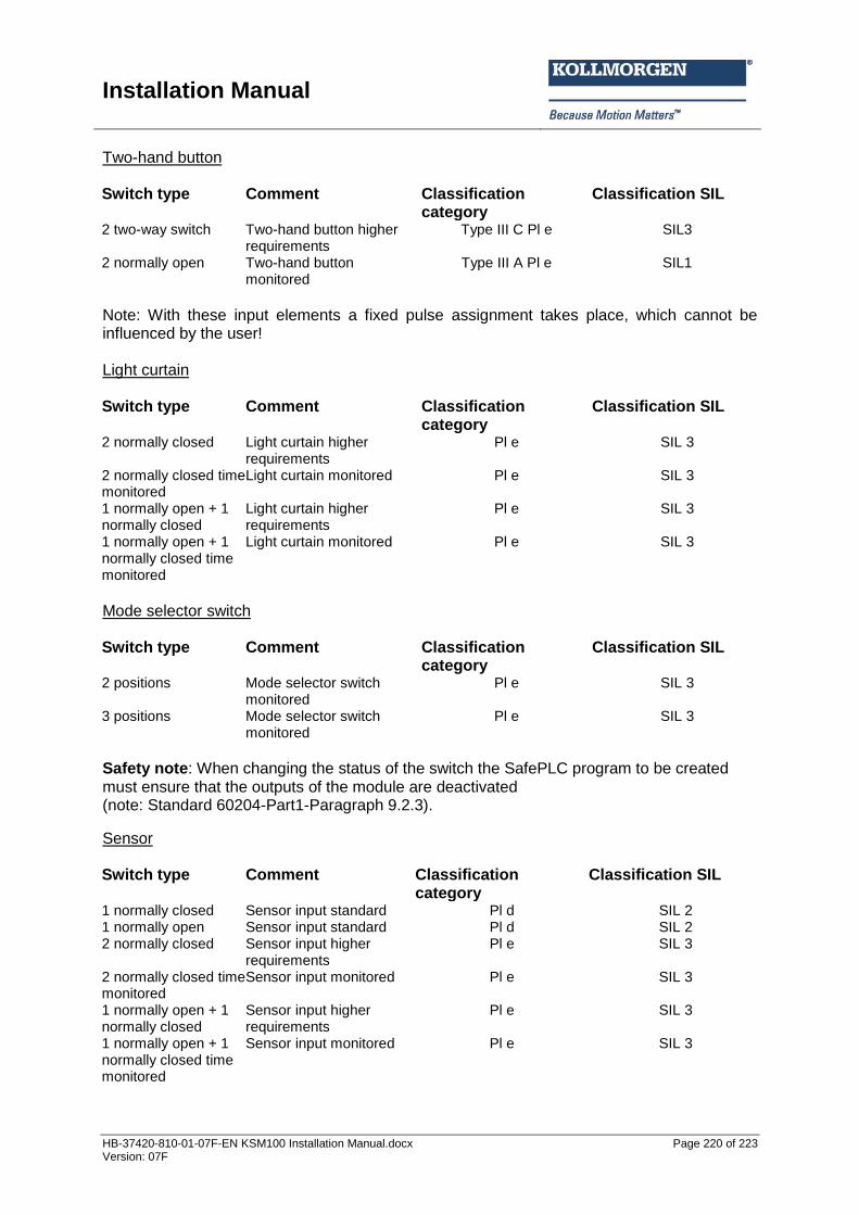
Installation Manual
HB-37420-810-01-07F-EN KSM100 Installation Manual.docx Page 220 of 223 Version: 07F
Two-hand button Switch type Comment Classification
category Classification SIL
2 two-way switch Two-hand button higher requirements
Type III C Pl e SIL3
2 normally open Two-hand button monitored
Type III A Pl e SIL1
Note: With these input elements a fixed pulse assignment takes place, which cannot be influenced by the user! Light curtain Switch type Comment Classification
category Classification SIL
2 normally closed Light curtain higher requirements
Pl e SIL 3
2 normally closed time monitored
Light curtain monitored Pl e SIL 3
1 normally open + 1 normally closed
Light curtain higher requirements
Pl e SIL 3
1 normally open + 1 normally closed time monitored
Light curtain monitored Pl e SIL 3
Mode selector switch
Switch type Comment Classification
category Classification SIL
2 positions Mode selector switch monitored
Pl e SIL 3
3 positions Mode selector switch monitored
Pl e SIL 3
Safety note: When changing the status of the switch the SafePLC program to be created must ensure that the outputs of the module are deactivated (note: Standard 60204-Part1-Paragraph 9.2.3).
Sensor Switch type Comment Classification
category Classification SIL
1 normally closed Sensor input standard Pl d SIL 2 1 normally open Sensor input standard Pl d SIL 2 2 normally closed Sensor input higher
requirements Pl e SIL 3
2 normally closed time monitored
Sensor input monitored Pl e SIL 3
1 normally open + 1 normally closed
Sensor input higher requirements
Pl e SIL 3
1 normally open + 1 normally closed time monitored
Sensor input monitored Pl e SIL 3

Installation Manual
HB-37420-810-01-07F-EN KSM100 Installation Manual.docx Page 221 of 223 Version: 07F
Start / reset element Switch type Comment Classification
category Classification SIL
1 normally open Alarm reset standard (evaluation of edge)
-- --
1 normally open Logic reset standard Pl d SIL 2
1 normally open Start monitoring standard (optional function)
-- --
Note: The alarm reset input can be operated with 24V continuous voltage and is edge triggered.

Installation Manual
HB-37420-810-01-07F-EN KSM100 Installation Manual.docx Page 222 of 223 Version: 07F
Appendix B
Approvals
The latest Certificates for Conformity to European Directives are located on the product DVD or can be downloaded from the Kollmorgen Website. Existing documents:
EU Declaration of Conformity according to EC Directives 2006/42/EC Appendix IV and 2004/108/EC
Functional Safety Certificate according to EC Directive 2006/42/EC Appendix I

Installation Manual
HB-37420-810-01-07F-EN KSM100 Installation Manual.docx Page 223 of 223 Version: 07F
About Kollmorgen
Kollmorgen is a leading provider of motion systems and components for machine builders. Through world-class knowledge in motion, industry-leading quality and deep expertise in linking and integrating standard and custom products, Kollmorgen delivers breakthrough solutions that are unmatched in performance, reliability and ease-of-use, giving machine builders an irrefutable marketplace advantage. For assistance with your application needs, visit www.kollmorgen.com or contact us at:
North America
Kollmorgen
203A West Rock Road Radford, VA 24141 USA Web: www.kollmorgen.com Mail: [email protected] Phone: 1-540-633-3545 Fax: 1-540-639-4162
Europe
Kollmorgen
Pempelfurtstraße 1 40880 Ratingen, Germany Web: www.kollmorgen.com Mail: [email protected] Phone: + 49-2102-9394-0 Fax: + 49 -2102-9394-3155
Asia
Kollmorgen
Rm 2205, Scitech Tower, China 22 Jianguomen Wai Street Web: www.kollmorgen.com Mail: [email protected] Phone: + 86-400-666-1802 Fax: +86-10-6515-0263