Embed Size (px)
Citation preview

Installation Manual
HB-37350-810-53-07F-EN KSM53 Installation Manual.docx Page 1 of 28
Installation Manual
KSM53
PROFINET

Installation Manual
HB-37350-810-53-07F-EN KSM53 Installation Manual.docx Page 2 of 28
Installation Manual for extension modules KSM53 Note: The German version if the original version of the installation manual Status: 06/2013 Subject to change without prior notification
The contents of this documentation has been collated with greatest care and corresponds with our present status of information.
However, we would like to point out, that this document cannot always be updated at the same time as further development of the product progresses. Information and specifications can be changed at any time. Please keep yourself informed about the current version under www.kollmorgen.com. Devices of the
Kollmorgen Europe GmbH Pempelfurtstraße 1 DE-40880 Ratingen

Installation Manual
HB-37350-810-53-07F-EN KSM53 Installation Manual.docx Page 3 of 28
Contents 1 IMPORTANT NOTES .......................................................................................... 4 1.1 Definitions ........................................................................................................................................... 4 1.2 Co-valid documents ............................................................................................................................. 4 1.3 Abbreviations used .............................................................................................................................. 5 2 SAFETY REGULATIONS .................................................................................... 6 2.1 Intended use ........................................................................................................................................ 6 2.2 General safety regulations ................................................................................................................... 6 2.3 Operation and service ......................................................................................................................... 7 2.4 Transport/storage ............................................................................................................................... 7 2.5 Scope of delivery ................................................................................................................................. 7 3 DEVICE DESCRIPTION AND OPERATION ....................................................... 8 3.1 Characteristic data ............................................................................................................................... 8 3.2 Device settings .................................................................................................................................... 8
4 SAFETY RELATED CHARACTERISTICS .......................................................... 9 5 CONNECTION AND INSTALLATION ................................................................. 9 5.1 General notes on installation ............................................................................................................. 10 5.2 Installation KSM-module ................................................................................................................... 11 5.3 Assembly on backplane bus ............................................................................................................... 11 5.4 CAN bus termination ......................................................................................................................... 11 5.5 Terminal assignment ......................................................................................................................... 12
6 START UP ......................................................................................................... 13 6.1 Procedure .......................................................................................................................................... 13 6.2 Parameterization ............................................................................................................................... 13
6.2.1 Installation GSDML-File ..................................................................................................... 13 6.2.2 Integration NetPro.............................................................................................................. 14 6.2.3 Integration HW-Config ....................................................................................................... 19 6.2.4 Extended functionality starting at version 1.2.0.1 ........................................................ 20 6.2.5 Configuration of KSM53 .................................................................................................... 23
6.3 Diagnostic-LED ................................................................................................................................... 25 6.4 Diagnostic Message ........................................................................................................................... 25 6.5 Structure user data ............................................................................................................................ 26 6.6 Modification / handling changes to the device .................................................................................. 26 7 MAINTENANCE ................................................................................................ 26 7.1 Exchanging a module ......................................................................................................................... 26
8 TECHNICAL DATA ........................................................................................... 27 8.1 Enviromental conditions .................................................................................................................... 27
Installation Manual
HB-37350-810-53-07F-EN KSM53 Installation Manual.docx Page 4 of 28
1 Important Notes Definition of individual target groups Project engineers for safe drive systems: Engineers and technicians Assembly, electric installation, maintenance and replacement of devices: Maintenance electricians and service technicians Commissioning, operation and configuration: Technicians and engineers
1.1 Definitions The designation KSM is used as generic term for all derivatives from the KSM product range. Wherever this description refers to a certain derivative, the complete designation is used. KSM53 is the short form for the communication device PROFINET KSM53. The term safe used in the following text in any case refers to the classification as a safe function for application up to Pl e acc. to EN ISO 13849-1 or SIL3 acc. to EN 61508. The system software SafePLC serves the purpose of configuring and programming KSM modules.
1.2 Co-valid Documents
Description Reference
General information about KSM devices and their usage.
KSM Installation manual KSM Programming manual
Description CAN data format.
TD-37350-810-51-xxF-EN Status Message Data
Table 1: co-valid documents
Note:
Thoroughly read the manuals before you start the installation and the commissioning of the KSM module.
Paying attention to the documentation is a prerequisite for trouble-free operation and fulfilment of possible warranty claims.

Installation Manual
HB-37350-810-53-07F-EN KSM53 Installation Manual.docx Page 5 of 28
1.3 Abbreviations Used
Abbreviation Meaning
AC Alternating voltage
AWL Anweisungsliste
ELIA Employer's liability insurance association
CLK Clock (cycle)
CPU Central Processing Unit
DC Direct voltage
DIN Deutsches Institut für Normung (German Institute for Standardization)
EMC Electromagnetic compatibility
EN European Standard
IP20 Degree of protection for housing
ISO International Organisation for Standardisation
LED Light Emitting Diode
PLC Programmable Logic Controller
POR Power on Reset
SDDC Safe Device To Device Communication
SELV Safety Extra Low Voltage
SSI Synchronous Serial Interface
VDE Verband der Elektrotechnik, Elektronik und Informationstechnik e. V. (association for el. engineering, electronics and information technology)
Table 2: Abbreviations

Installation Manual
HB-37350-810-53-07F-EN KSM53 Installation Manual.docx Page 6 of 28
2 Safety Regulations
2.1 Intended Use The communication device EtherCAT KSM55 is an extension for the devices of the KSM11/12 series for non safe data exchange over PROFINET protocol.
2.2 General Safety Regulations
Safety Note:
In order to avoid damage to persons and property only qualified personnel is entitled to work on the device. The term qualified personnel refers to persons who have successfully completed electrotechnical training and are fully familiar with the applicable rules and standards of electrical engineering. The qualified person must become familiar with the operating instructions (see IEC364, DIN VDE0100).
The qualified must have profound knowledge of the nartional accident prevention regulations
The use of the device must be strictly limited to the intended use as specified in the following list. The values of data listed under section 3.2 Characteristic device data must also be observed.
The contents of this installation manual is restricted to the basic function of the device or its installation. The Programming instructions KSM11/12 contains a more detailed description of the programming and re-parameterization of the devices. Exact knowledge and understanding of these instructions is mandatory for a new installation or modification of device functions or device parameters.
Commissioning (i.e. starting up the intended operation) is only permitted in strict compliance with the EMC-directive.
The wiring and connecting instructions in chapter Installation must be strictly followed.
The applicable VDE-regulations and other special safety regulations of relevance for the application must be strictly followed.
Evidence of the configured monitoring functions as well as their parameters and links must be issued by means of a validation report.
Do not install or operate damaged products. Report damages immediately to the responsible forwarding agent.

Installation Manual
HB-37350-810-53-07F-EN KSM53 Installation Manual.docx Page 7 of 28
Never open the housing and/or make unauthorized conversions. Inputs and outputs for standard functions or digital and analog data transmitted via communication modules must not be used for safety relevant applications.
WARNING: Using our devices contrary to the rules and conditions specified hereunder can lead to injuries or fatalities as well as damage to connected devices and machines! This will also cause the loss of all warranty and compensation claims against Kollmorgen.
2.3 Operation and Service The module must always be de-energized before installation and removal, or before disconnecting signal lines. For this purpose all live supply lines to the device must be checked for safe isolation from supply When installing or removing the module appropriate measures must be applied to prevent electrostatic discharge to the externally arranged terminal and plug connections. Contact with such terminals should be reduced to a minimum and earthing should by means of e.g. an earthing strap should take place before and during these procedures.
2.4 Transport/Storage Information concerning transport, storage and proper handling must be strictly followed. The climate related specifications in chapter Technical data must be complied with.
2.5 Scope of Delivery
The scope of delivery contains:
Extension device PROFINET KSM53
GSDML-file
Installation manual
Backplane bus plug

Installation Manual
HB-37350-810-53-07F-EN KSM53 Installation Manual.docx Page 8 of 28
3 Device Description and Operation SM53 is a communication device and can only be used with a basic device KSM11 or KSM12 (and their variants).
Together with the KSM basic device this device works as a gateway from back plane CAN bus to PROFINET. The user has the possibility to send the status message data () to PROFINET DP. Max. user data from 8 CAN messages can be send.
Starting at software version 1.2.0.1 data from SPS to KSM Device can be transferred via PROFINET. These data are sent from KSM53 device via cofigurabale CAN telegram to the KSM Basic device. This is to control the functional inputs of the KSM.
Device has to be configured as a PROFINET slave device. Corresponding GSDML-file is included with the device.
Ethernet data rate will be 100Mbit/s in full duplex mode. Size of output data is maximum 64 byte.
3.1 Characteristic Data
Device KSM53
Response time Variable, depends on used slots, between 24 and 68ms
Number of CAN objects 1 bis 8
Data size CAN telegram 8 Byte
CAN ID Standard
Table 3: Charasteristic data
3.2 Device Settings
On frontside of the device following components are visible:
Image 1: Front Side
Dip Switches for Bus Termination (see chapter CAN bus termination)
Diagnostic-LED’s (see chapter Diagnostic-LED)
PROFINET-Plug (see chapter Terminal assignment)

Installation Manual
HB-37350-810-53-07F-EN KSM53 Installation Manual.docx Page 9 of 28
4 Safety Related Characteristics KSM55 can only be used as a non safe communication with PROFINET-protocol. The Proof-Test-inteval according to EN61508 is up to 20 years – after this time the device hast o be replaced
Safety Note: The safety regulations and EMC guidelines has to be observed.
5 Connection and Installation KSM53 has to be connected to a basic device (KSM11, KSM12 ) with a back plan. The installation of the PROFINET connector must be done after the installation instruction of the PNO. Example: KSM 55 together with KSM12:
Image 2: Device Connection
KSM53 KSM12

Installation Manual
HB-37350-810-53-07F-EN KSM53 Installation Manual.docx Page 10 of 28
5.1 General Notes on Installation Strictly follow the safety regulations when installing! Degree of protection IP20 Route all signal lines for the interfacing of digital inputs and contact monitoring separately. You should in any case disconnect 230VAC voltages from low voltage power lines, if these voltages are used in connection with the application. The cable lengths for digital inputs and outputs must normally not exceed 30 m. If the cable lengths exceeds 30 m you must apply appropriate measures for fault exclusion concerning impermissible overvoltage. Appropriate measures include e.g. lightning protection for outdoor lines, overvoltage protection of the indoor system, protected routing of cables. Measures concerning the electromagnetic compatibility (EMC) The KSM module is intended for use in the drive environment and meets the EMC-requirements mentioned above. It is also assumed that the electromagnetic compatibility of the overall system is ensured by application of appropriate measures.
Safety Notes:
Electric power supply lines of the KSM and discontinuous-action lines of the power converter must be isolated from each other.
Signal lines and power lines of the power converter must be routed through separate cable ducts. The distance between the cable ducts should be minimum 10 mm.
EMC-compliant installation of the power converter technology in the environment of the KSM module must be assured. Special attention must be paid to the routing of cables, the shielding of motor cables and the connection of the braking resistor. Strict compliance with the installation instructions of the power converter manufacturer is mandatory.
All contactors in the environment of the power converter must be equipped with appropriate suppressor circuits.
Suitable measures to protect against overvoltages must be applied.

Installation Manual
HB-37350-810-53-07F-EN KSM53 Installation Manual.docx Page 11 of 28
5.2 Installation KSM-Module
The module is solely to be installed in control cabinets with a degree of protection of at least IP54. The modules must be vertically fastened on a top hat rail. The ventilation slots must be kept unobstructed, to ensure adequate air circulation inside the module. For more information see Installation Manual KSM.
5.3 Assembly on Backplane Bus
Image 3: Assembly
For more information see Installation Manual KSM.
5.4 CAN Bus Termination Dip switch 1 activates the termination resistor for CAN backplane communication. Dip switch 2 is not used.
12
ON
Dip switch 1 120 ohm resistor for termination (ON (= right position) = active, OFF = open)
Dip switch 2 Not used

Installation Manual
HB-37350-810-53-07F-EN KSM53 Installation Manual.docx Page 12 of 28
5.5 Terminal Assignment
Image 4: Assignment RJ45
Pins 1 … 8 Pin Assignment RJ45
Pin Name Description Color
1 TX+ Tranceive Data + white-orange
2 TX- Tranceive Data - orange
3 RX+ Receive Data + white-green
4 nc. Not used blue
5 nc. Not usedt white-blue
6 RX- Receive Data - green
7 nc. Not used white-brown
8 nc. Not usedt brown
Installation Manual
HB-37350-810-53-07F-EN KSM53 Installation Manual.docx Page 13 of 28
6 Start Up
6.1 Procedure Start-up must only be performed by qualified personnel! Strictly follow the safety regulations when commissioning! The following shows an example of a start-up in Step 7.
Note: The S7 CPU hast o be activated before the KSM53 device is switched on.
6.2 Parameterization First the GSDML File hast o be included Therefore the GSDML file (short GSD file) has to copy into the Step 7 program folder.
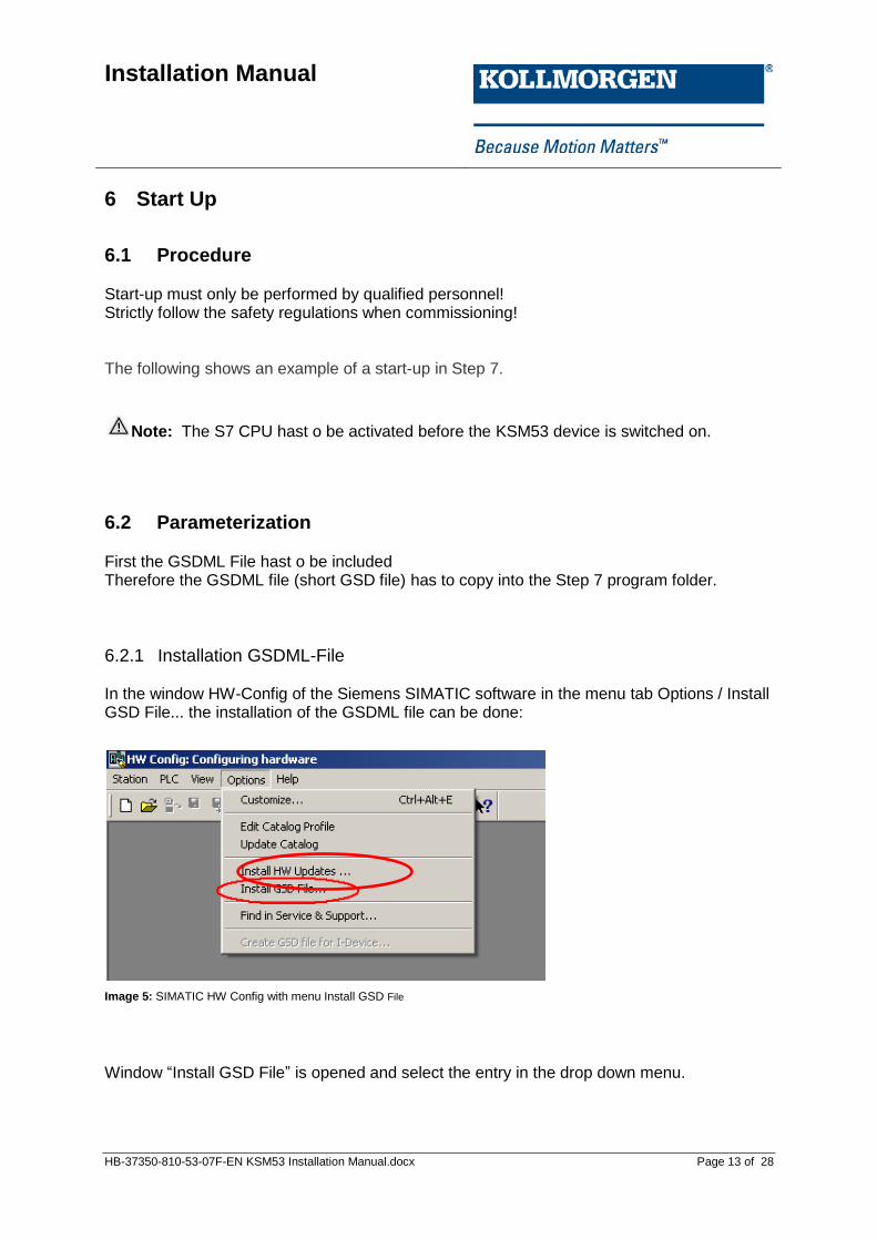
6.2.1 Installation GSDML-File In the window HW-Config of the Siemens SIMATIC software in the menu tab Options / Install GSD File... the installation of the GSDML file can be done:
Image 5: SIMATIC HW Config with menu Install GSD File
Window “Install GSD File” is opened and select the entry in the drop down menu.
Installation Manual
HB-37350-810-53-07F-EN KSM53 Installation Manual.docx Page 14 of 28
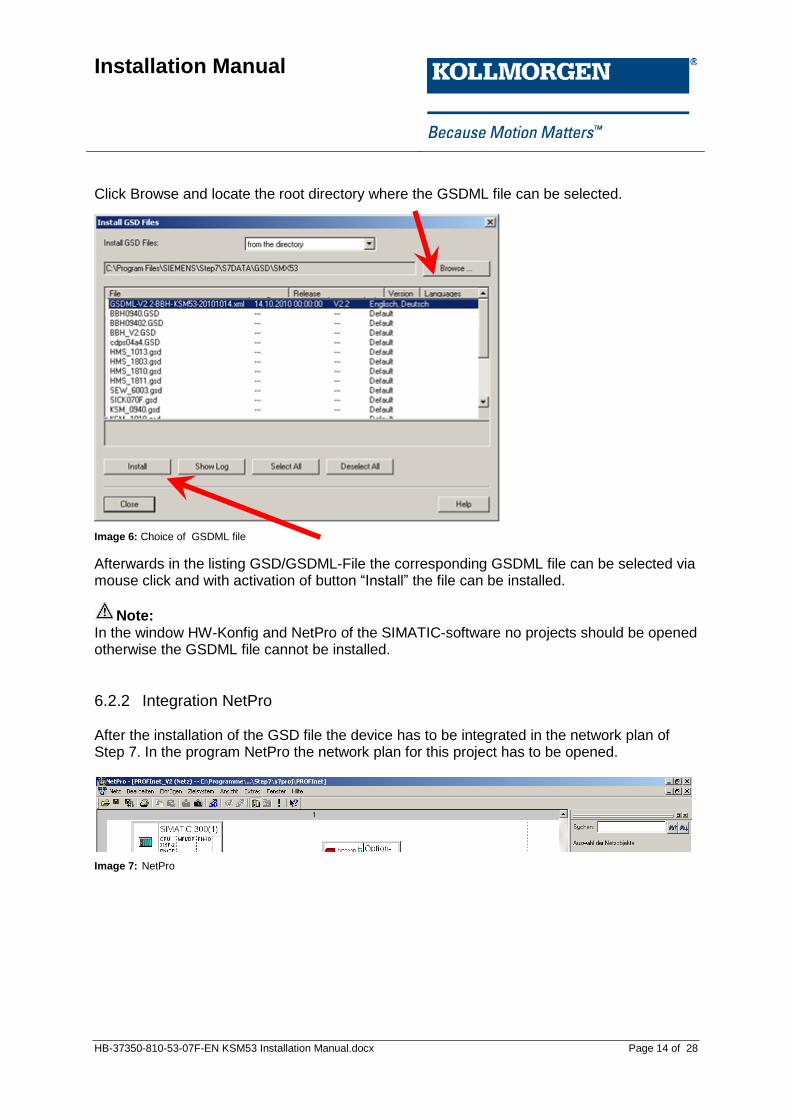
Click Browse and locate the root directory where the GSDML file can be selected.
Image 6: Choice of GSDML file
Afterwards in the listing GSD/GSDML-File the corresponding GSDML file can be selected via mouse click and with activation of button “Install” the file can be installed.
Note: In the window HW-Konfig and NetPro of the SIMATIC-software no projects should be opened otherwise the GSDML file cannot be installed.
6.2.2 Integration NetPro After the installation of the GSD file the device has to be integrated in the network plan of Step 7. In the program NetPro the network plan for this project has to be opened.
Image 7: NetPro
Installation Manual
HB-37350-810-53-07F-EN KSM53 Installation Manual.docx Page 15 of 28
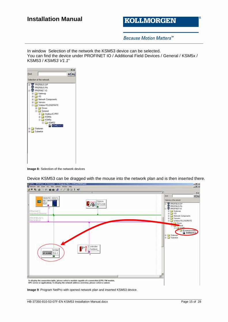
In window Selection of the network the KSM53 device can be selected. You can find the device under PROFINET IO / Additional Field Devices / General / KSM5x / KSM53 / KSM53 V1.1“
Image 8: Selection of the network devices
Device KSM53 can be dragged with the mouse into the network plan and is then inserted there.
Image 9: Program NetPro with opened network plan and inserted KSM53 device.
Installation Manual
HB-37350-810-53-07F-EN KSM53 Installation Manual.docx Page 16 of 28
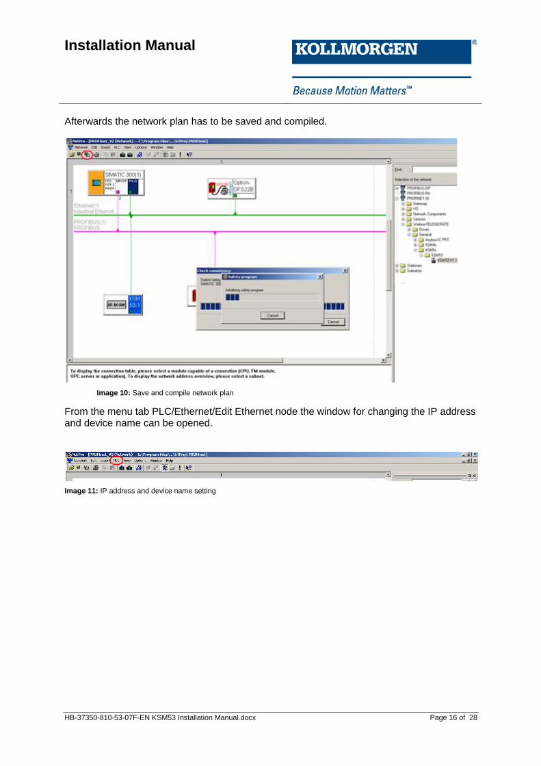
Afterwards the network plan has to be saved and compiled.
Image 10: Save and compile network plan
From the menu tab PLC/Ethernet/Edit Ethernet node the window for changing the IP address and device name can be opened.
Image 11: IP address and device name setting

Installation Manual
HB-37350-810-53-07F-EN KSM53 Installation Manual.docx Page 17 of 28
Image 12: Edit Ethernet nodes
By clicking Browse... the following window “Browse Network” is opened:
Image 13: Dialog box Browse Network with two PROFINET nodes
Installation Manual
HB-37350-810-53-07F-EN KSM53 Installation Manual.docx Page 18 of 28
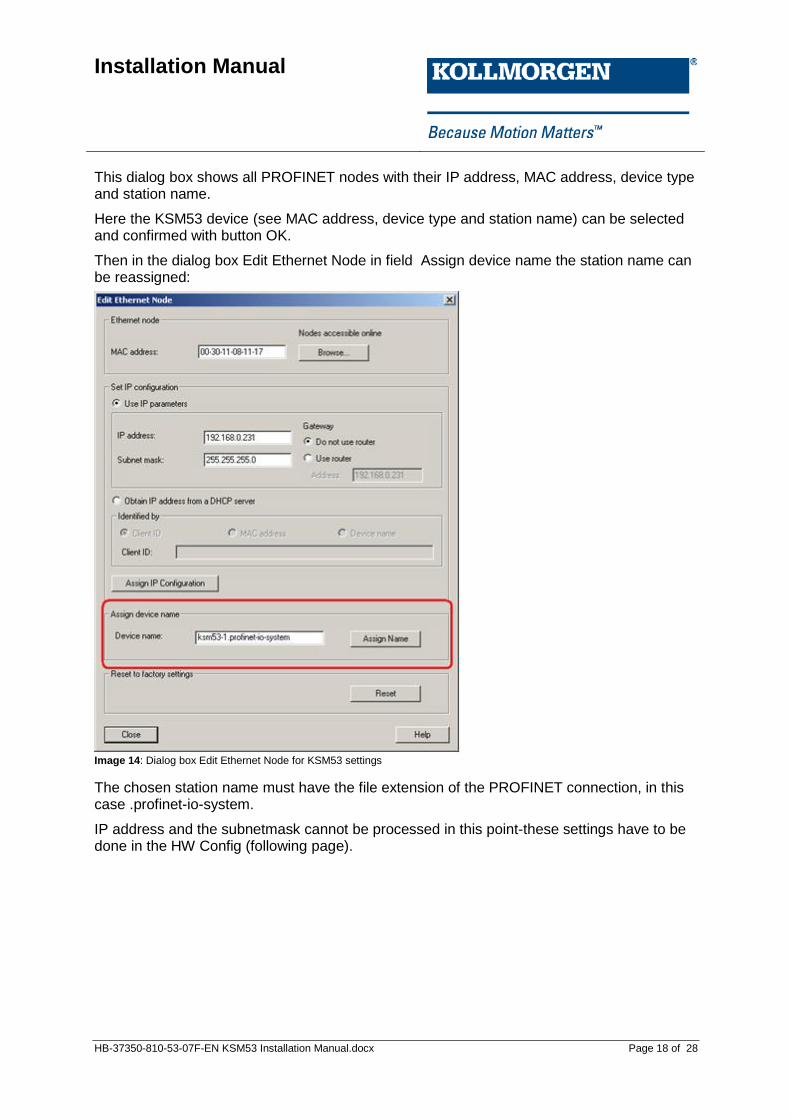
This dialog box shows all PROFINET nodes with their IP address, MAC address, device type and station name.
Here the KSM53 device (see MAC address, device type and station name) can be selected and confirmed with button OK.
Then in the dialog box Edit Ethernet Node in field Assign device name the station name can be reassigned:
Image 14: Dialog box Edit Ethernet Node for KSM53 settings
The chosen station name must have the file extension of the PROFINET connection, in this case .profinet-io-system.
IP address and the subnetmask cannot be processed in this point-these settings have to be done in the HW Config (following page).
Installation Manual
HB-37350-810-53-07F-EN KSM53 Installation Manual.docx Page 19 of 28
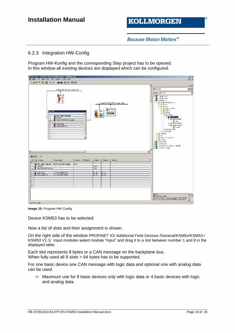
6.2.3 Integration HW-Config Program HW-Konfig and the corresponding Step project has to be opened. In this window all existing devices are displayed which can be configured.
Image 15: Program HW Config
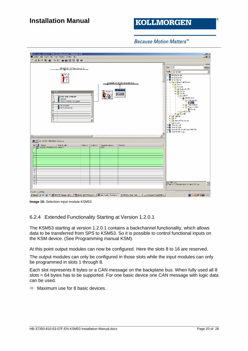
Device KSM53 has to be selected. Now a list of slots and their assignment is shown.
On the right side of the window PROFINET IO/ Additional Field Devices /General/KSM5x/KSM53 / KSM53 V1.1/ Input modules select module “Input” and drag it to a slot between number 1 and 8 in the displayed table.
Each slot represents 8 bytes or a CAN message on the backplane bus. When fully used all 8 slots = 64 bytes has to be supported.
For one basic device one CAN message with logic data and optional one with analog data can be used.
Maximum use for 8 basic devices only with logic data or 4 basic devices with logic and analog data.
Installation Manual
HB-37350-810-53-07F-EN KSM53 Installation Manual.docx Page 20 of 28
Image 16: Selection input module KSM53
6.2.4 Extended Functionality Starting at Version 1.2.0.1 The KSM53 starting at version 1.2.0.1 contains a backchannel functionality, which allows data to be transferred from SPS to KSM53. So it is possible to control functional inputs on the KSM device. (See Programming manual KSM). At this point output modules can now be configured. Here the slots 8 to 16 are reserved.
The output modules can only be configured in those slots while the input modules can only be programmed in slots 1 through 8.
Each slot represents 8 bytes or a CAN message on the backplane bus. When fully used all 8 slots = 64 bytes has to be supported. For one basic device one CAN message with logic data can be used.
Maximum use for 8 basic devices.

Installation Manual
HB-37350-810-53-07F-EN KSM53 Installation Manual.docx Page 21 of 28
Image 17: HW Konfig with opened project and KSM53 device
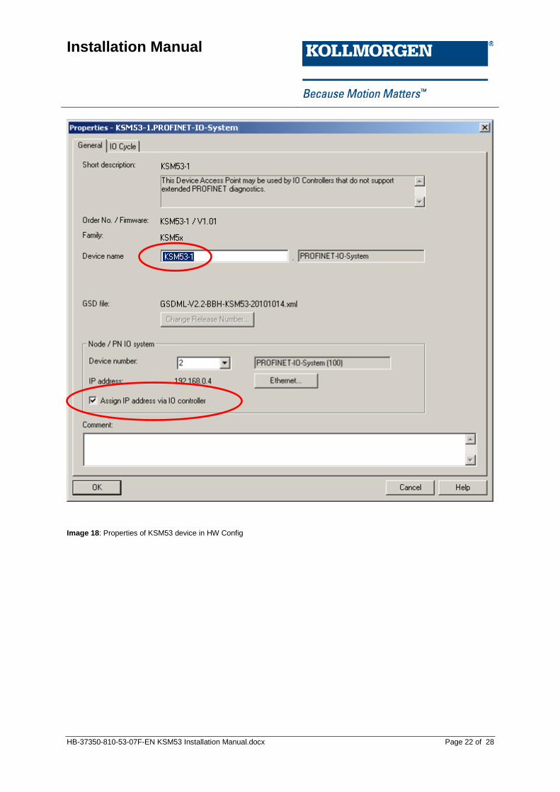
The input and output module is now available in the hardware configuration. By double clicking on the corresponding module start address of the inputs or outputs can be changed. Then close the Properties window of the module. Double-clicking object KSM53 in the dialog box Properties via the menu item Ethernet… the IP address of KSM53 can be configured. This IP address is assigned automatically to the KSM53 device when connected. The check box “Assign IP address via IO-Controller” in window “Properties” has to be activated. The station name has to match to the configured name in the network plan.
Installation Manual
HB-37350-810-53-07F-EN KSM53 Installation Manual.docx Page 22 of 28
Image 18: Properties of KSM53 device in HW Config

Installation Manual
HB-37350-810-53-07F-EN KSM53 Installation Manual.docx Page 23 of 28
6.2.5 Configuration of KSM53 Now the configuration possibilities for the internal CAN bus (backplane) of the KSM series will be explained. The configuration data are shown in Properties dialog box of the KSM device on tab Parameter and can be changed there. For one basic device maximum 2 CAN messages for output data (input data SPS) and 1 message for input data (output data SPS) can be used. Maximum 8 (only logic data) or 4 (logic and analog data) basic devices can operate with the available 8 slots By configuring the CAN ID an allocation to the slots of the basic devices is generated.
Image 19: Adjustable parameters of the KSM53 for CAN module backplane bus

Installation Manual
HB-37350-810-53-07F-EN KSM53 Installation Manual.docx Page 24 of 28
Folgende Einstellungen können ausgeführt werden:
Interval Time Timeout for internal CAN communication
CAN-ID Slot 1...8 CAN identifier for the particular slot CAN input data. This has to match the configured CAN ID of this slot assigned basic device. CAN ID of the basic device is configured in the SafePLC. If a slot is not used the value for CAN ID is set to 0.
CAN-ID Slot 9...16 Starting with version1.2.0.1 CAN ID for slot 9 … 16 be set additionally. This corresponds to the CAN ID for sending data from KSM53 to the KSM basic device. This has to match the configured CAN ID of this slot assigned basic device. CAN ID of the basic device is configured in the SafePLC. If a slot is not used the value for CAN ID is set to 0.
Table 4: CAN-ID slots
Note: Only when connected to the PROFINET master system the configured data is transferred to the KSM53 – otherwise the default settings are valid:
Parameter Default-value
Interval Time 500
CAN-ID slot 1 192
CAN-ID slot 2 194
CAN-ID slot 3 196
CAN-ID slot 4 198
CAN-ID slot 5 200
CAN-ID slot 6 202
CAN-ID slot 7 204
CAN-ID slot 8 206
Table 5: CAN-ID Default values
Starting with version 1.2.0.1 following modifications apply: The KSM53 from this version contains a feedback functionality. This data can be transferred from the SPS to the KSM53; the data is send over backplane bus to basic device. In the Properties dialog box of slot 0, the CAN IDs can be set for both the input modules as well as for the output modules per slot Unused slots are set to CAN ID = 0
Note: There must be at least one input and one output module. Starting with version 1.3.0.1 this restriction no longer applies but unused slots has to be occupied with empty modules and the CAN ID is set to 0.

Installation Manual
HB-37350-810-53-07F-EN KSM53 Installation Manual.docx Page 25 of 28
6.3 Diagnostic-LED The KSM53 device has three LEDs. Conditions:
LED Colour Mode Description
RUN Green Blinking Device OK
DP
Green Constant PROFINET-Connection active
Green Blinking PROFINET-connection lost, parameters valid
Red Blinking Transfered parameters not valid
XB
Green Blinking internal CAN-message (KSM) received
Green Constant Verarbeitung OK
Red Blinking Missing CAN message or CAN message out of CAN WD Timeout time
Red Constant Device error (contact the manufacturer)
Table 6: LED-Conditions
6.4 Diagnostic Message The KSM53 can send in case of error channel specific diagnostic message via PROFINET. These can be displayed on the SIEMENS SIMATIC software. The following table gives an overview of the possible diagnostic messages.
Error Code Description
300 Parameters not correct received or not valid.
Table 7: Error Codes

Installation Manual
HB-37350-810-53-07F-EN KSM53 Installation Manual.docx Page 26 of 28
6.5 Structure User Data Internal structure of the CAN data frame see installation manual
TD-37350-810-51-xxF-xx Status Message Data.pdf
6.6 Modification/Handling Changes to the Device Maintenance work must solely be carried out by qualified personnel. Regular maintenance work is not required. Repair
The devices must always be replaced as whole units Repair work on the device can only be performed in the factory. Warranty
By opening the module without permission the warranty will become null and void.
7 Maintenance
7.1 Exchanging a Module The following should be noted when exchanging:
Disconnect the electric power converter from the main supply.
PROFINET-plug disconnect.
Take the module off the top hat rail and pack up EMC-compliant
Mount the new module on the top hat rail
PROFINET-plug connect
Activate power supply via backplane plug.
Note: Pluggable connections of the KSM module must generally not be disconnected or connected in live condition. There is a danger of sensor damage, particularly with connected position or speed sensors.

Installation Manual
HB-37350-810-53-07F-EN KSM53 Installation Manual.docx Page 27 of 28
8 Technical Data
8.1 Enviromental Conditions Class of protection IP 20 Ambient temperature 0 °C* ... 50 °C Storage temperature -25°C…70°C Lifetime 20 years at 50 °C ambient
Table 8: Enviromental Conditions

Installation Manual
HB-37350-810-53-07F-EN KSM53 Installation Manual.docx Page 28 of 28
About Kollmorgen
Kollmorgen is a leading provider of motion systems and components for machine builders. Through world-class knowledge in motion, industry-leading quality and deep expertise in linking and integrating standard and custom products, Kollmorgen delivers breakthrough solutions that are unmatched in performance, reliability and ease-of-use, giving machine builders an irrefutable marketplace advantage. For assistance with your application needs, visit www.kollmorgen.com or contact us at:
North America
Kollmorgen
203A West Rock Road Radford, VA 24141 USA Web: www.kollmorgen.com Mail: [email protected] Phone: 1-540-633-3545 Fax: 1-540-639-4162
Europe
Kollmorgen
Pempelfurtstraße 1 40880 Ratingen, Germany Web: www.kollmorgen.com Mail: [email protected] Phone: + 49-2102-9394-0 Fax: + 49 -2102-9394-3155
Asia
Kollmorgen
Rm 2205, Scitech Tower, China 22 Jianguomen Wai Street Web: www.kollmorgen.com Mail: [email protected] Phone: + 86-400-666-1802 Fax: +86-10-6515-0263