Embed Size (px)
Citation preview
KSB Mechanical Seal
Double Mechanical Seals
for Etabloc, Etanorm Type SeriesBack-to-Back ArrangementWith Seal Supply System
Supplementary OperatingManual
Legal information/Copyright
Supplementary Operating Manual Double Mechanical Seals
Original operating manual
All rights reserved. The contents provided herein must neither be distributed, copied, reproduced,edited or processed for any other purpose, nor otherwise transmitted, published or made available to athird party without the manufacturer's express written consent.
Subject to technical modification without prior notice.
© KSB SE & Co. KGaA, Frankenthal 16/02/2018
Contents
3 of 12Double Mechanical Seals
Contents
1 Supplementary Operating Manual ....................................................................................................... 41.1 General.............................................................................................................................................................. 41.2 Technical data................................................................................................................................................... 41.3 Dismantling the shaft seal ............................................................................................................................... 41.4 Fitting the shaft seal ........................................................................................................................................ 51.5 Seal supply system ............................................................................................................................................ 7
1.5.1 Applications.......................................................................................................................................... 71.5.2 Connections.......................................................................................................................................... 71.5.3 Requirements to be met by the seal supply system........................................................................... 7
1.6 General assembly drawing with list of components ...................................................................................... 9
1 Supplementary Operating Manual
4 of 12 Double Mechanical Seals
1 Supplementary Operating Manual
1.1 GeneralThis supplementary operating manual accompanies the installation/operatingmanual. All information contained in the installation/operating manual must beobserved.
Table 1: Relevant operating manuals
Type series Reference number of the installation/operatingmanual
Etabloc 1173.8
Etanorm 1311.8
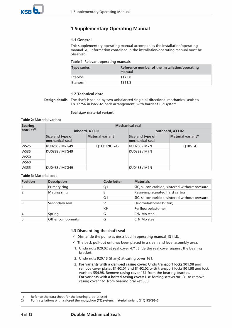
1.2 Technical dataDesign details The shaft is sealed by two unbalanced single bi-directional mechanical seals to
EN 12756 in back-to-back arrangement, with barrier fluid system.
Seal size/ material variant
Table 2: Material variant
Bearingbracket1)
Mechanical seal
inboard, 433.01 outboard, 433.02
Size and type ofmechanical seal
Material variant Size and type ofmechanical seal
Material variant2)
WS25 KU028S / M7G49 Q1Q1K9GG-G KU028S / M7N Q1BVGG
WS35 KU038S / M7G49 KU038S / M7N
WS50
WS60
WS55 KU048S / M7G49 KU048S / M7N
Table 3: Material code
Position Description Code letter Materials
1 Primary ring Q1 SiC, silicon carbide, sintered without pressure
2 Mating ring B Resin-impregnated hard carbon
Q1 SiC, silicon carbide, sintered without pressure
3 Secondary seal V Fluoroelastomer (Viton)
K9 Perfluoroelastomer
4 Spring G CrNiMo steel
5 Other components G CrNiMo steel
1.3 Dismantling the shaft sealü Dismantle the pump as described in operating manual 1311.8.
ü The back pull-out unit has been placed in a clean and level assembly area.
1. Undo nuts 920.02 at seal cover 471. Slide the seal cover against the bearingbracket.
2. Undo nuts 920.15 (if any) at casing cover 161.
3. For variants with a clamped casing cover: Undo transport locks 901.98 andremove cover plates 81-92.01 and 81-92.02 with transport locks 901.98 and lockwashers 554.98. Remove casing cover 161 from the bearing bracket.For variants with a bolted casing cover: Use forcing screws 901.31 to removecasing cover 161 from bearing bracket 330.
1) Refer to the data sheet for the bearing bracket used2) For installations with a closed thermosyphon (TS) system: material variant Q1Q1K9GG-G
1 Supplementary Operating Manual
5 of 12Double Mechanical Seals
4. Pull shaft sleeve 523 with the rotating assemblies of mechanical seals 433.01 and433.02 off shaft 210.
5. Take seal cover 471 off shaft 210.
6. Remove circlip 932.05 and the ring from casing cover 161.
7. Remove the stationary assembly (mating ring) of mechanical seal 433.01 fromcasing cover 161.
8. Remove the stationary assembly (mating ring) of mechanical seal 433.02 fromseal cover 471.
9. Loosen and remove the rotating assembly of mechanical seals 433.01 and 433.02from shaft sleeve 523.
10. Remove and dispose of gasket 400.15 (for WS25 joint ring 411.15) and gasket400.75.
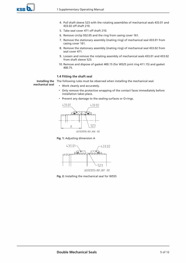
1.4 Fitting the shaft sealInstalling the
mechanical sealThe following rules must be observed when installing the mechanical seal:
▪ Work cleanly and accurately.
▪ Only remove the protective wrapping of the contact faces immediately beforeinstallation takes place.
▪ Prevent any damage to the sealing surfaces or O-rings.
Fig. 1: Adjusting dimension A
Fig. 2: Installing the mechanical seal for WS55
1 Supplementary Operating Manual
6 of 12 Double Mechanical Seals
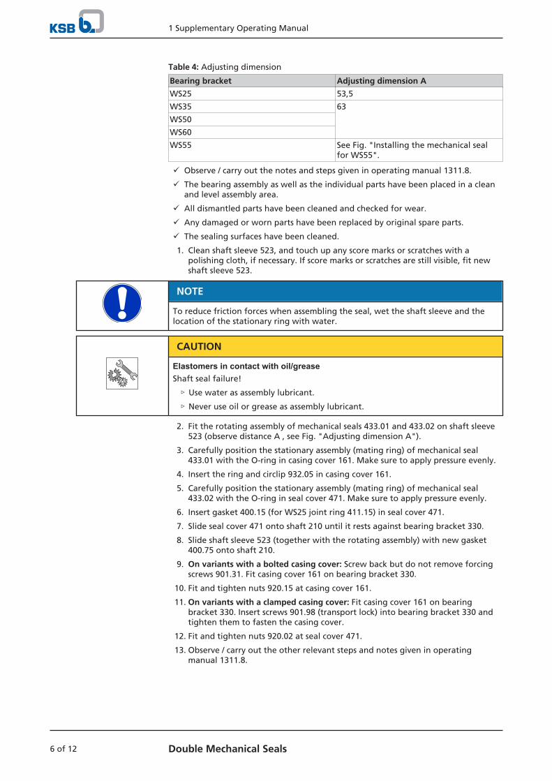
Table 4: Adjusting dimension
Bearing bracket Adjusting dimension A
WS25 53,5
WS35 63
WS50
WS60
WS55 See Fig. "Installing the mechanical sealfor WS55".
ü Observe / carry out the notes and steps given in operating manual 1311.8.
ü The bearing assembly as well as the individual parts have been placed in a cleanand level assembly area.
ü All dismantled parts have been cleaned and checked for wear.
ü Any damaged or worn parts have been replaced by original spare parts.
ü The sealing surfaces have been cleaned.
1. Clean shaft sleeve 523, and touch up any score marks or scratches with apolishing cloth, if necessary. If score marks or scratches are still visible, fit newshaft sleeve 523.
NOTE
To reduce friction forces when assembling the seal, wet the shaft sleeve and thelocation of the stationary ring with water.
CAUTION
Elastomers in contact with oil/greaseShaft seal failure!
▷ Use water as assembly lubricant.
▷ Never use oil or grease as assembly lubricant.
2. Fit the rotating assembly of mechanical seals 433.01 and 433.02 on shaft sleeve523 (observe distance A , see Fig. "Adjusting dimension A").
3. Carefully position the stationary assembly (mating ring) of mechanical seal433.01 with the O-ring in casing cover 161. Make sure to apply pressure evenly.
4. Insert the ring and circlip 932.05 in casing cover 161.
5. Carefully position the stationary assembly (mating ring) of mechanical seal433.02 with the O-ring in seal cover 471. Make sure to apply pressure evenly.
6. Insert gasket 400.15 (for WS25 joint ring 411.15) in seal cover 471.
7. Slide seal cover 471 onto shaft 210 until it rests against bearing bracket 330.
8. Slide shaft sleeve 523 (together with the rotating assembly) with new gasket400.75 onto shaft 210.
9. On variants with a bolted casing cover: Screw back but do not remove forcingscrews 901.31. Fit casing cover 161 on bearing bracket 330.
10. Fit and tighten nuts 920.15 at casing cover 161.
11. On variants with a clamped casing cover: Fit casing cover 161 on bearingbracket 330. Insert screws 901.98 (transport lock) into bearing bracket 330 andtighten them to fasten the casing cover.
12. Fit and tighten nuts 920.02 at seal cover 471.
13. Observe / carry out the other relevant steps and notes given in operatingmanual 1311.8.
1 Supplementary Operating Manual
7 of 12Double Mechanical Seals
1.5 Seal supply system
1.5.1 Applications
In order to function properly, the mechanical seals require a barrier fluid. The barrierfluid completely fills the space between the inboard and the outboard mechanicalseal. It serves two purposes:
▪ Dissipate friction heat
▪ Prevent the fluid handled from entering the sealing gap
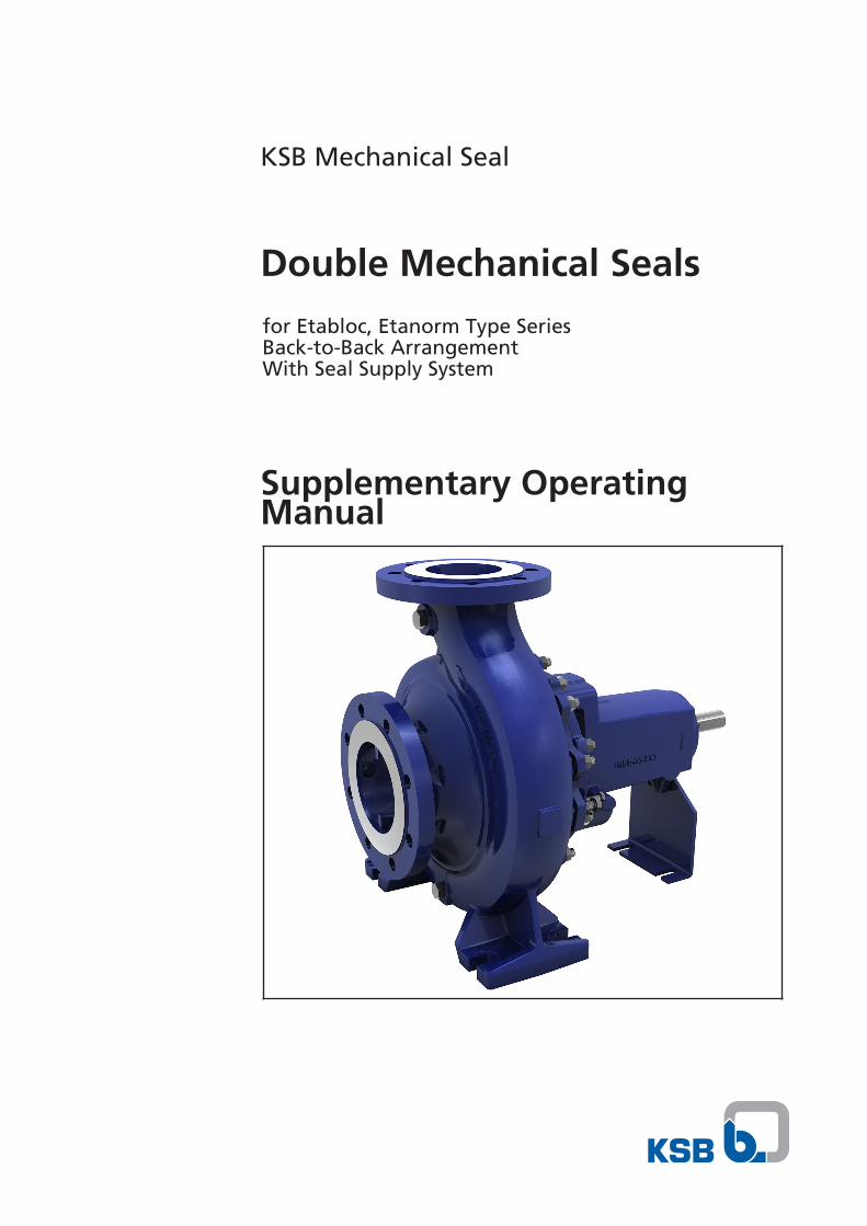
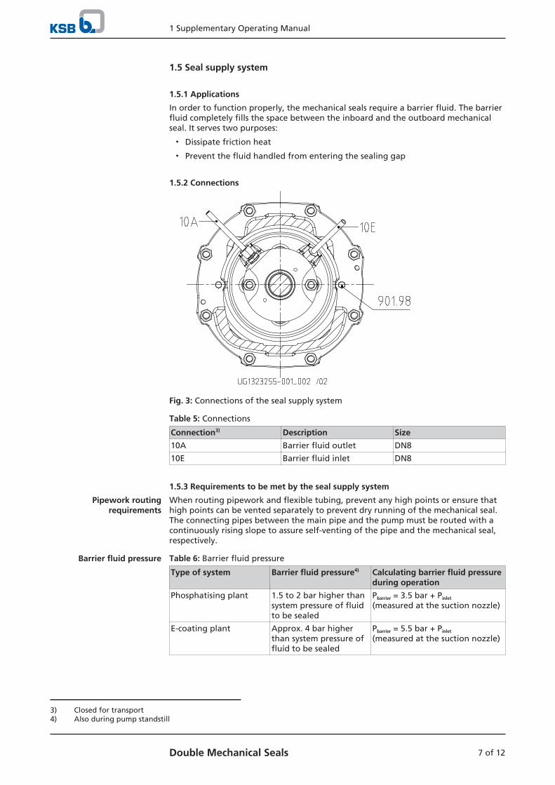
1.5.2 Connections
Fig. 3: Connections of the seal supply system
Table 5: Connections
Connection3) Description Size
10A Barrier fluid outlet DN8
10E Barrier fluid inlet DN8
1.5.3 Requirements to be met by the seal supply system
Pipework routingrequirements
When routing pipework and flexible tubing, prevent any high points or ensure thathigh points can be vented separately to prevent dry running of the mechanical seal.The connecting pipes between the main pipe and the pump must be routed with acontinuously rising slope to assure self-venting of the pipe and the mechanical seal,respectively.
Barrier fluid pressure Table 6: Barrier fluid pressure
Type of system Barrier fluid pressure4) Calculating barrier fluid pressureduring operation
Phosphatising plant 1.5 to 2 bar higher thansystem pressure of fluidto be sealed
Pbarrier = 3.5 bar + Pinlet
(measured at the suction nozzle)
E-coating plant Approx. 4 bar higherthan system pressure offluid to be sealed
Pbarrier = 5.5 bar + Pinlet
(measured at the suction nozzle)
3) Closed for transport4) Also during pump standstill
1 Supplementary Operating Manual
8 of 12 Double Mechanical Seals
Large-scale industrial plants
Barrier fluid ▪ Ultrafiltrate (residual solvent content approx. 50% of the solvent in the paint)
▪ Return barrier fluid to ultrafiltration stage.
Monitor the ultrafiltrate for contamination (clouding). In the event of amalfunction make sure the ultrafiltrate does not reach the barrier fluid vessel.
Barrier fluid pressure ▪ Install a pressure boosting pump to ensure the barrier fluid pressure required.
▪ Fit a by-pass valve in the return line, for instance, to maintain the minimumpressure. This valve must close tightly during idle periods and be used inconjunction with a sufficiently sized bladder accumulator to maintain thepressure in the system (e.g. in the event of a power failure or operating errors).
▪ To ensure equal distribution of the barrier fluid, install orifice plates in the linesdownstream of the mechanical seals. Use downstream valves for fine-tuning only.
▪ Secure the barrier fluid system against barrier pressure failure (e.g. due to powerfailure), as the absence of barrier pressure will result in mechanical seal failure.
Barrier fluid temperature ▪ The temperature of the barrier fluid should be within the processing range ofthe paint (normally 25 to +30 °C).
Circulation flow ▪ To prevent the formation of paint deposits in the seal supply system and tostabilise the temperature in the sealing gap, we recommend a circulation flow of2.5 - 5 l/min per seal.
Small systems
Barrier fluid ▪ Ultrafiltrate
▪ DI water with a slightly increased solvent content, e.g. 5 – 10 % butyl glycol
Barrier fluid pressure Ensure sufficient barrier fluid pressure by means of a continuous nitrogen supply orcompressed air supply via a suitable pressure regulating valve.
Thermosyphon system ▪ The thermosyphon vessel should be located approximately 1 metre above thecentreline of the pump and connected with pipework.
▪ Install pipes made of chrome nickel molybdenum cast steel with an insidediameter ≥ 9 mm and a steady rise, in order to avoid air pockets and consequentdry running of the mechanical seals.
▪ Each pump must be provided with its own thermosyphon system so that themechanical seals can be monitored individually and failure of one mechanicalseal will not pose a risk to the others.
▪ The pipe bend radius must be as large as possible to keep pipe friction losses aslow as possible.
▪ In order to stabilise the temperature, a circulating pump must be installed in thesystem. (Contact operator about explosion protection requirements.)
▪ Monitor the barrier fluid level by means of a level switch (contact operator aboutexplosion protection requirements).
▪ Barrier fluid refill is by means of a manual refill pump.
▪ When a closed thermosyphon system is used, we recommend to use a SiC/SiCcombination on the outboard mechanical seal as well, to avoid wear or damageto the seal faces caused by paint deposits or sticking.
Cooling Cooling of the thermosyphon system is required if the following limits are exceeded:
▪ Speeds > 1450 rpm
▪ Seal diameter > 60 mm
▪ Barrier fluid pressure > 6 bar
▪ Ambient temperature > 30 ℃
1 Supplementary Operating Manual
9 of 12Double Mechanical Seals
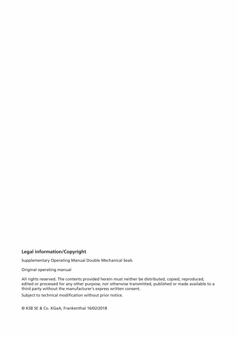
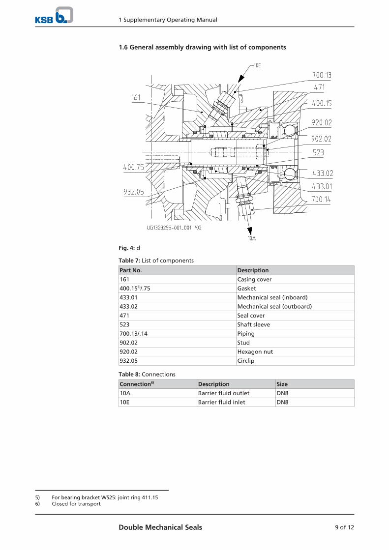
1.6 General assembly drawing with list of components
Fig. 4: d
Table 7: List of components
Part No. Description
161 Casing cover
400.155)/.75 Gasket
433.01 Mechanical seal (inboard)
433.02 Mechanical seal (outboard)
471 Seal cover
523 Shaft sleeve
700.13/.14 Piping
902.02 Stud
920.02 Hexagon nut
932.05 Circlip
Table 8: Connections
Connection6) Description Size
10A Barrier fluid outlet DN8
10E Barrier fluid inlet DN8
5) For bearing bracket WS25: joint ring 411.156) Closed for transport


KSB SE & Co. KGaA
Johann-Klein-Straße 9 • 67227 Frankenthal (Germany)
Tel. +49 6233 86-0
www.ksb.com
1311
.801
/02-
EN