Embed Size (px)
Citation preview
________________________________ _______________________________ ____________________________________________
Chapter 7 Farm Distribution Components National Engineering Handbook Part 652 Irrigation Guide
KS652.0710 State supplement - farm distribution components (a) General information This part contains technical information required for the design of various irrigation practices. The practices covered herein are primarily engineering practices and are required for the efficient development and operation of irrigation systems. For further information concerning the design and documentation of these practices, refer to the Kansas Practice Documentation Requirements in the electronic Field Office Technical Guide (FOTG). (b) Conservation Practice 447, Irrigation
System, Tailwater Recovery (1) Procedure for design of irrigation tailwater embankment ponds Embankment fills made to impound irrigation tailwater will meet the design requirements and specifications listed in Kansas Conservation Practice Standard 378, Pond. In addition to the reasons cited in Section 652.0705, tailwater recovery systems may be considered for one or more of the following reasons: • Section 208 of the Pollution Control act generally
treats tailwater as a non-point source of pollution.
• Tailwater and reuse systems are used in areas of deep-well irrigation because they require much less power to pump water from a tailwater pit than from the aquifer.
Storage requirements for irrigation tailwater will be determined using the same criteria as for tailwater pits.
(2) Procedure for design of irrigation tailwater pits (i) Depth--Design water surface shall be at the flowline elevation of the inlet structure or 1 foot (0.3 m) below the lowest irrigable land elevation adjacent to the pit, whichever is lower. Retrievable tailwater depth shall be a minimum of 5 feet (1.5 m) and a maximum of 12 feet (3.6 m). Excavated depth (below design water surface elevation) shall be design water depth plus 1 foot (0.3 m). (ii) Slopes and top width--Excavated and embankment slopes shall not be steeper than 3:1, except 2:1 slopes may be used for the sides of the pit in soils that will be stable at the slope. Slopes will usually not be flatter than 4:1, except that one or both ends may be flattened to 6:1 for ease of construction and cleanout. Minimum top width of berms and dikes shall be 8 feet (2.4 m). (iii) Mechanical inlets structures--Inlet structures shall be provided to convey the tailwater and/or storm runoff into the pit without erosion damage to the entrance channel or sides of the pit. These structures may consist of chutes, drop structures, or pipes (minimum size - 10 inches [25 cm] in diameter) using corrugated metal, welded steel, plastic, concrete, or other approved material. Structures will be designed in accordance with Kansas conservation practice standards and specifications in Section IV of the eFOTG. Use Kansas standard drawings (when available) that are on the Kansas Web site or that are in the Kansas Supplement to Chapter 6 of National Engineering Handbook Part 650 (NEH 650), Engineering Field Handbook. The inlet structures must have the capacity to satisfy the operating needs of the system. (iv) Auxiliary spillway or storm bypass--Pits shall be surrounded by berms and dikes to prevent surface water from entering the pits at points other than the mechanical inlet structure. A storm bypass or auxiliary spillway shall be provided that will pass the runoff from a 25-year, 24-hour frequency Antecedent Moisture Condition (AMC) II storm. Tops of the berms and dikes shall be at least 1 foot (0.3 m) above the maximum water surface in the pit or the spillway, whichever is higher, when passing this storm.
(210-VI-NEH 652, Amend. KS17, Aug. 2007) 1

________________________________ _______________________________ ____________________________________________
Chapter 7 Farm Distribution Components National Engineering Handbook Part 652 Irrigation Guide (v) Size
Condition A--Pumpback is intermittent. Volume of storage shall be designed on the basis of the following: Select Ti, which is the estimated time required (in hours). Ti is listed in Column 11, in the “Irrigation Design” charts in Section KS652.0605(b)(2). The Ti selected should represent the most restrictive design condition for the system. For example, if both border and furrow irrigation methods are planned, furrow irrigation with a high water demand crop (such as corn) should be used to select Ti. The number of sets (N) to be irrigated with pumpback water per pumpback cycle is usually 2. The maximum number is 2 and the minimum is 1. Determine whether or not tailwater from the pumpback pump also enters the pit. Tp is the pumpback time in hours, Tp = N x Ti. Discharge rate (q) in gallons per minute of the pumpback pump is determined by multiplying the primary source (Q) in gallons per minute by a variable factor (Ca). Values of Ca vary according to soil intake families. Table KS7-1 below lists the values of Ca for the various intake families. Table KS7-1
Intake Ca Factors Family Maximum Median Minimum
0.1 to 0.3 0.80 0.60 0.40 0.5 0.60 0.46 0.33 1.0 to 3.0 0.40 0.30 0.20 Values of q may be adjusted +10 percent if needed to fit the pump discharge rates of commercial suppliers. The rate of tailwater flow into the collection pits is based on the intake rates of the contributing areas along with the discharge rates of wells, turnouts, and pumps delivering the irrigation water. Use a decimal percentage (%) of Q returning as tailwater from the percentages shown in Table KS7-2 for the soil intake families listed.
Table KS7-2 Percentage (% or %*) of Primary Intake (Q) or q for Pumpback Flow Family Delivered as Tailwater 0.1 to 0.3 20 0.5 15 1.0 to 3.0 10 Also, select from Table KS7-2 a decimal percentage (%*) of q for pumpback flow returning as tailwater. Find the total of the average field tailwater from the primary source (%Q) and the average tailwater from the pumpback flow (%*q) or (%Q + %q). This is the total tailwater inflow into the pit. To keep the tailwater system in equilibrium, q for pumpback flow of the pumpback pump minus the total inflow (%Q + %q) must equal the volume of the tailwater pit (Vs) in acre-inches, or storage = (outflow - inflow) or Vs = q – (%Q + %q) x Tp = acre-inches 450 Example: Given: Richfield silt loam Intake Family = 0.3 Q = 1,000 gallons per minute (gpm) Slope Group = 0.2% Ti = 16.3 hours N = 2 Find: Tp, q, %Q, %*q, and Vs
Tp = N x Ti = 2 x 16.3 = 32.6 hours From Table KS7-1, Ca = 0.6 (median value) q = Ca x Q = 0.6 x 1,000 = 600 gpm
(210-VI-NEH 652, Amend. KS17, Aug. 2007) 2
________________________________ _______________________________ ____________________________________________
Chapter 7 Farm Distribution Components National Engineering Handbook Part 652 Irrigation Guide
From Table KS7-2, % = 20%, %* = 20%, then %Q = 0.20 x 1,000 = 200 gpm, %*q = 0.20 x 600 = 120 gpm
Vs = q - (%Q + %*q) x Tp 450
Vs = 600 - (200 + 120) x 32.6 450 = 20.3 acre-inches
Condition B--Where continuous pumping is desired and the inflow is sufficient both in rate and duration to sustain such a system, the sump (as a minimum) needs to be only large enough to accommodate the pumping.
Pumpback (once started) is continuous as long as the irrigation continues uninterrupted. The maximum value of N shall be one (1). The volume of storage (Vs) and q for pumpback flow are determined as shown below. The following equations may be used to determine q in gallons per minute:
q = % x Q, where % = Cb 1 - %* 1 - %* or q = Cb x Q Q, q, %, and %* are the same units as used for Condition A. Cb factors used to determine q are found in Table KS7-3.
Table KS7-3 Cb Factors Estimated Decimal % of Discharge Q Flowing into the Pit 0.10 0.15 0.20 Estimated Decimal % of q for Pumpback Flow into the Pit None 0.10 0.15 0.20 None 0.10 0.15 0.20 None 0.10 0.15 0.20 Pumpback Factor Cb 0.100 0.111 0.118 0.125 0.150 0.167 0.177 0.188 0.200 0.222 0.236 0.250
Volume of tailwater storage (Vs) needed is determined using the following equation:
Vs = (%Q) x Ti = acre-inches 450 Example Given: Q = 1,000 gpm, Ti = 16.3 hrs., % = 0.20, %* = 0.20 Find: Cb, q, and Vs
Cb = % = 0.20 = 0.25 1 - %* 1 - 0.20 or refer to Table KS7-3 to find Cb q = Cb x Q = 0.25 x 1,000 = 250 gpm
Vs = (0.20 x 1,000) x 16.3 450 = 7.2 acre-inches
(vi) Excavated volume--Approximate excavated volume (Ve) may be found as follows:
Ve = 175 x Vs (ac. in.) = cubic yards (cu. yd.) where 175 is the conversion from ac. in. to cu. yd. with the excavated soil density at 77%.
Condition C--To provide for adequate storage (gallons) for intermittent pumpback systems not indicated, use the following equation:
Pond Volume (V) = Q x T or Vs = q x Tp 3 3 Where: Q = Volume of pumpback system (gpm) T = Irrigation set time (hours)
(210-VI-NEH 652, Amend. KS17, Aug. 2007) 3
________________________________ _______________________________ ____________________________________________
Chapter 7 Farm Distribution Components National Engineering Handbook Part 652 Irrigation Guide
(vii) Figuring length width, and volume for excavated pits
Volume equation is V = d x (A1 + 4M + A2 ) 162 Where: d = Depth (feet) A1 = Top area (ft2) M = Medium area (ft2) A2 = Bottom area (ft2) 162 = 27 ft3/yd3 x 6 (sum of areas) Computing length of pit bottom for desired volume, depth, and width Where: l = Bottom length of the pit (feet) V = Volume (cubic yards) w = Bottom width (feet) d = Depth (feet) Table KS7-4 Equation for Length at Bottom of Pit
Side Slope
End Slope
Equation for l
3:1 3:1 27V – 12d3 – 3d2w 3d2 + dw
2:1 4:1 81V – 32d3 – 12d2w 6d2 + 3dw
3:1 4:1 27V – 16d3 – 4d2w 3d2 + dw
4:1 4:1 81V – 64d3 – 12d2w 12d2 + 3dw
3:1 6:1 - 4:1 27V – 20d3 – 5d2w 3d2 + dw
An Excel spreadsheet is available to perform the calculations. One needs to input the desired depth of the pit, bottom width, side, end slopes, and storage volume.
Example Given: Storage volume (Vs) of a pit = 20.3 ac-inches
Side Slopes = 3:1 End Slopes = 6:1 - 4:1 Depth = 8 feet Bottom Width = 50 feet
Find: Estimated excavation volume (Ve), bottom
length, and actual excavated volume
Ve = 175 x Vs Ve = 175 x 20.3 = 3,552.5 (use 3,553 cu. yds.) From Table KS7-4, for w = 50', d = 8', 3:1 side slope and 6:1 - 4:1 end slope
L = 27V – 20d3 – 5d2w 3d2 + dw
L = (27 x 3553) – (20 x 83) – (5 x 82 x 50) (3 x 82) + (8 x 50)
= (95,931) – (10,240) – (16,000)
(192) + (400)
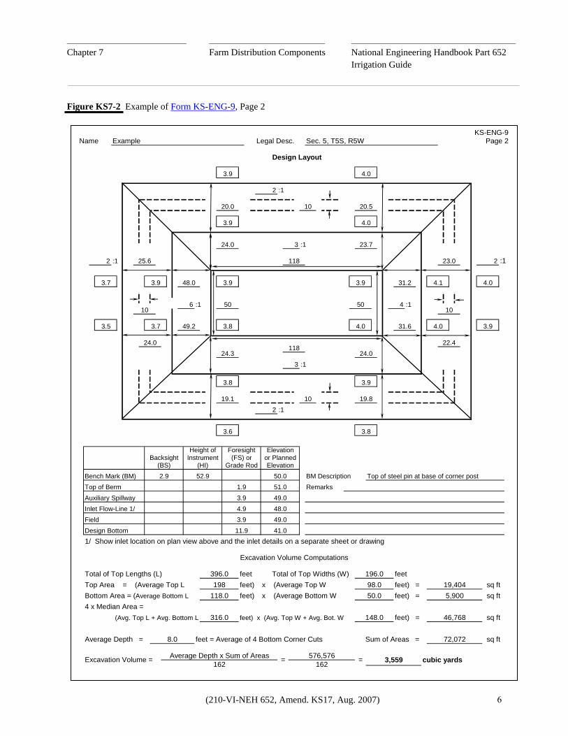
= 69,691 = 117.7 (use 118 feet) 592 Actual excavated volume:
Ve = d x (Al + (4x M) + A2) 162 = 8 (198 x 98 + 4 (158 x 74) + 50 x 118) 162 = 8 (72,072) = 3,559 cu. yds. 162
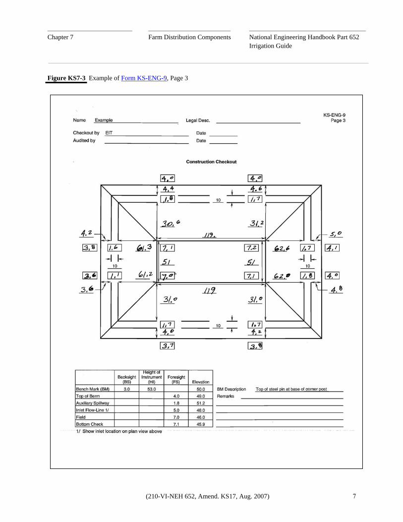
(vii) Sample Problem--See Figures KS7-1, KS7-2, and KS7-3 as examples of Form KS-ENG-9 that is to be filled out for a tailwater recovery pit.
(210-VI-NEH 652, Amend. KS17, Aug. 2007) 4

________________________________ _______________________________ ____________________________________________
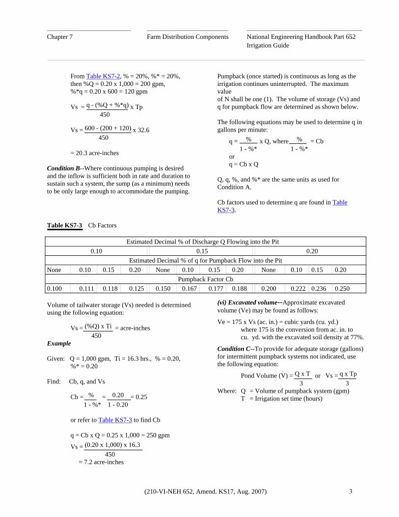
Chapter 7 Farm Distribution Components National Engineering Handbook Part 652 Irrigation Guide Figure KS7-1 Example of Form KS-ENG-9, Page 1
`
DateDate
T Θ Q = 1000 gpmll⊥Tll⊥Tll⊥Tll⊥Tll⊥Tll⊥Tllollllolll o \ /l
/ \
ii
---- ---- ---- ---- l-- --l l----l
iiiV
iVii
iiii
iiiV
iiVi
iiViiiiii
--l l------ ----
Viiii
---- ----l------ --l ----l----ll--
% S
lope
% slope
% S
lope
---- --l l----
% slope % slope
----------------------> ---------------------->
0.2 0.2
% S
lope
0.2
---------------------->
0.2 % slope
---------------------->
% S
lope
3549x
175 x =20.3=x
Condition A - Intermittent Pumpback
Scale 1" =
20.3
32.6
Volume of Storage (Vs) =q - (% x Q + % x q)
450
450
600 0.20
50118
feetfeet
Estimated Excavation Volume (Ve) = 175 x Vs =
feetLength
3
Design Dimensions
Tailwater Inflow to the Pit as Follows:
=
Condition B - Continuous Pumpback
Percentage (%) of Q = / 100 = / 100 =
q = Ca Factor x Q = =
:1
%
6 :1
x Tp =
Location Map
See design procedure in National Engineering Handbook (NEH) Part 652, Irrigation Guide, KS652.07(b). Use equations for pit bottom length from Table KS7-4 or other methods.
cubic yards
:1
Minimum Total Depth = 7 feet (per Conservation Practice Standard 447)
acre-inches
4EndEnd
Sides
8
Slopes:
gpm
- ( 1000
=
x
600x 1000
)600x
gpm
2
0.632.6 hours
Pumpback Time (Tp) = N x Ti =
gpmPrimary Source Pumping Rate (Q)Pump-Back Tailwater:
0.2020 0.2020
Will Enter the Pit
Will Not Enter the Pit
% of Pumpback (q) =
Irrigation Set Time (Ti) 16.3 hoursNumber of Sets (N): 2 orX
Haskell
Before any investigation or construction activity, the excavator is responsible for calling Kansas One-Call at 800-344-7233 (800-DIG-SAFE).
Ident. No.County
ExampleSec. 5, T5S, R5W
450
x x
Row Spacing 40 inches
Width
X
1
16.3
IntermittentSystem is: (Mark one for each selection below)
SoilCrop corn
Intake Family 0.3Field Slope 0.2
x
1000
0.20+
acre-inches
Vs =% x Q x Ti
450
Irrigation System, Tailwater Recovery - 447
Approved by
Layout by
NameLegal Desc.
KS-ENG-9
N
Rev. 7/05
X
Richfield
Continuous
USDANRCS
Remarks Locate inlet pipe on east side of pit as shown
660
Date
q = Cb Factor x Q = =
Design Information
Designed by Checked by
Date
=
Depth
(210-VI-NEH 652, Amend. KS17, Aug. 2007) 5
________________________________ _______________________________ ____________________________________________
Chapter 7 Farm Distribution Components National Engineering Handbook Part 652 Irrigation Guide Figure KS7-2 Example of Form KS-ENG-9, Page 2
Excavation Volume Computations
24.3
24.0 23.7
24.0
:1
3
19.8
118
3.8
:1
4.0
3.94.031.6
22.4
223.0
4.0
4.0
10
10 20.5
:1
50
4.0
3.9
:1
:1
24.0
3.73.5
3.7
118
6 :1 50
3.9
3
2.9
3.9
19.1
49.2 3.8
2
Backsight(BS)
48.0
3.6
Elevation52.9 50.0 BM Description
ForesightHeight of
KS-ENG-9Page 2Example Legal Desc. Sec. 5, T5S, R5W
10
25.6
Design Layout
2
3.9
3.9
20.0
Name
2 :1
Bottom Area = (Average Bottom LTop Area = (Average Top L
118.0
Total of Top Lengths (L) 396.0198
Total of Top Widths (W)
feet)
feetfeet)
:1
31.2 4.1
410
Top of steel pin at base of corner post
3.8
3.9
sq ft
sq ft
19,4045,900
sq ft
46,768
48.0
feet) =x (Average Bottom W 50.0feet) =
41.0
feet196.098.0x (Average Top W
feet) =
162 3,559576,576162 =Average Depth x Sum of Areas cubic yards=
72,072
4 x Median Area =
Average Depth =
feet) x (Avg. Top W + Avg. Bot. W(Avg. Top L + Avg. Bottom L
8.0
316.0
Sum of Areas = feet = Average of 4 Bottom Corner Cuts
148.0
sq ft
11.9
51.0
49.03.9
Remarks
Instrument(HI)
Inlet Flow-Line 1/Field
Top of BermAuxiliary Spillway 49.0
4.9
Design Bottom
3.9
Excavation Volume =
Bench Mark (BM)
1/ Show inlet location on plan view above and the inlet details on a separate sheet or drawing
(FS) orGrade Rod
Elevationor Planned
1.9
(210-VI-NEH 652, Amend. KS17, Aug. 2007) 6
________________________________ _______________________________ ____________________________________________
Chapter 7 Farm Distribution Components National Engineering Handbook Part 652 Irrigation Guide Figure KS7-3 Example of Form KS-ENG-9, Page 3
(210-VI-NEH 652, Amend. KS17, Aug. 2007) 7
________________________________ _______________________________ ____________________________________________
Chapter 7 Farm Distribution Components National Engineering Handbook Part 652 Irrigation Guide (c) Design criteria for irrigation pipelines This is a summary of design criteria for irrigation pipelines and includes various technical aids used in pipeline design. In Section IV of the eFOTG, refer to the following Kansas conservation practice standards for detailed information and refer to the documentation requirements for information relating to the documentation of low-pressure underground plastic pipelines.
• 430DD, Irrigation Water Conveyance, High-Pressure, Underground, Plastic Pipeline (includes polyvinyl chloride [PVC], Acrylonitrile-Butadiene-Styrene [ABS], and polyethylene [PE] plastic pipe)
• 430EE, Irrigation Water Conveyance, Low-Pressure, Underground, Plastic Pipeline (includes PVC, ABS and PE plastic pipe)
• 431, Above Ground Multi-Outlet Pipeline (includes Aluminum and PVC gated pipe)
(1) Design criteria summary (i) Working pressure--The maximum allowable working pressure is that pressure at which the pipe is warranted to operate continuously without failure. All pipelines should be designed to operate at a pressure less than or equal to the working pressure. Working pressure varies greatly from one pipe material to another; refer to the specific pipeline standard for detailed criteria. (ii) External load limit--This is the maximum allowable load due to soil and vehicle weight that may be applied to the pipe. This factor is usually controlled by placing limits on the maximum and minimum amount of fill that may be placed over a pipeline. (iii) Capacity--The pipeline shall be designed to have sufficient flow capacity to deliver the amount of water necessary to meet planned irrigation requirements. Where water is supplied by a well, the pipeline is generally designed to carry the total well output. (iv) Velocity--Some pipe materials have a maximum velocity limitation. This limitation is usually imposed to minimize damage from surge pressures. The
following conservation practices standards contain velocity limitations: • 430DD and 430EE - 5 feet/second maximum
• 431 - 7 feet/second maximum (v) Friction losses--This section indicates the minimum allowable roughness coefficient to be used in calculating pressure or head loss in a pipeline due to friction. (vi) Outlets--These are appurtenances to the pipeline that deliver water to a field or another water conveyance or storage area. Typical examples include line gate valves, risers and alfalfa valves, and hydrants. (vii) Check valves--These are devices that prevent reverse flow back into a pump and/or well after the pump is shut down. Check valves help prevent pump damage and help minimize the chance of polluted water in the pipeline flowing back into the well. Check valves are required on all Natural Resources Conservation Service (NRCS) jobs. (viii ) Stands--A stand is a device used to convey water from the source of supply into the pipeline. In most cases, the stand is installed between the pump discharge and the beginning of the pipeline. Stands are generally constructed of steel and aid in controlling air entrapment, surge pressure, and vacuum or negative pressure.
(ix) Vents--A vent is a vertical conduit attached to the pipeline that is open on one end to the atmosphere. The purpose of a vent is to allow for overflow when pressure exceeds maximum allowable working pressure. Vents are rarely used at this time, having been replaced by pressure relief valves.
(x) Pressure relief valves--These valves are set to overflow when a specified pressure is reached. This valve protects the pipeline from rupture due to excessive pressure.
Pipe materials conforming to Kansas Conservation Practice 430DD--Pressure relief valves shall be no smaller than 1/4 the nominal pipeline diameter and shall be set to open at a pressure no greater than 5
(210-VI-NEH 652, Amend. KS17, Aug. 2007) 8

________________________________ _______________________________ ____________________________________________
Chapter 7 Farm Distribution Components National Engineering Handbook Part 652 Irrigation Guide
(xv) Materials protection--Certain pipe materials require protective measures to prevent early failure from chemical attack. Aluminum and steel require protection from corrosion. Sulfates and salts may degrade concrete pipe. These substances may occur in irrigation water, the soil in contact with the pipeline, or both.
pounds per square inch (psi) above the pressure rating of the pipe.
Pipe materials conforming to Kansas Conservation Practice 430EE--Pressure relief valves shall have the capacity to discharge the design flow rate of the pipeline at a pressure no greater than 50 percent more than the working pressure of the pipe. The valves should be set to open at the pipe working pressure.
Refer to Figure KS7-5 for an example of a typical pump installation including appurtenances.
Pressure relief valves are to be installed on all pump stands and at the end of the pipeline if there is no valve installed there. On a system that does not have a pump stand, a pressure relief valve shall be installed between the check valve and the beginning of the pipeline.
(2) Design tables The following design tables may be used in the design of pipeline systems. Included are tables for friction loss in various pipe materials and appurtenances, along with size and capacity guidelines for pressure relief valves and air and vacuum release valves installed on low-pressure plastic pipelines.
(xi) Air and vacuum release valves--These valves allow air to escape during pipeline filling and allow air to enter the line to prevent vacuum formation during draining operations. Air and vacuum release valves are to be installed at the following points:
• On the pump stand
For plastic pipelines with working pressures greater than 50 psi, refer to Exhibit 3-7 in NEH 650, Engineering Field Handbook, for head loss tables.
• At any summit in the pipeline • At the end of the pipeline • At any in-line control device, such as a line gate
valve or hub end gate • At any location where there are changes in pipeline
grade in a downward direction of flow greater than 10 degrees (18 percent)
Refer to the specific standard for criteria regarding size requirements for air and vacuum release valves. (xii) Drainage--Provisions for draining the pipeline shall be made if recommended by the manufacturer or required to prevent damage from freezing. (xiii) Flushing--A valve shall be installed at the end of the pipeline to allow for flushing if a sediment accumulation hazard exists. (xiv) Thrust control--Thrust blocks or anchors are to be installed wherever there is an abrupt change in pipeline grade, alignment, or reduction in pipe size. Thrust blocks absorb the axial thrust at these locations, thereby preventing rupture or separation of the pipeline.
(210-VI-NEH 652, Amend. KS17, Aug. 2007) 9

________________________________ _______________________________ ____________________________________________
Chapter 7 Farm Distribution Components National Engineering Handbook Part 652 Irrigation Guide Figure KS7-4 Typical Pump Installation
(210-VI-NEH 652, Amend. KS17, Aug. 2007) 10
________________________________ _______________________________ ____________________________________________
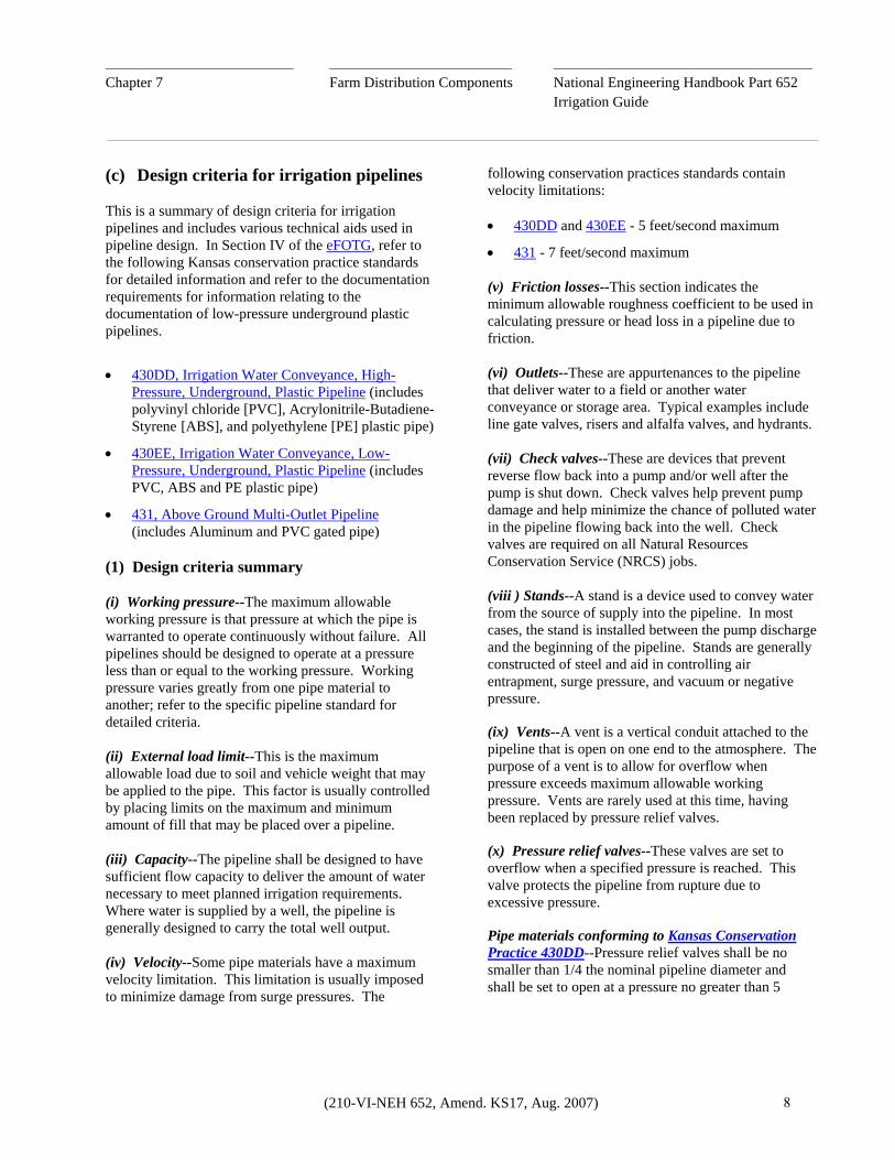
Chapter 7 Farm Distribution Components National Engineering Handbook Part 652 Irrigation Guide Table KS7-5 Friction Loss (in feet/1000 feet) in 22 Pounds per Square Inch (psi) Polyvinyl Chloride (PVC) Pipe 1/
Flow Pipe Size (inches) (gpm) 4 2/ 6 2/ 8 2/ 10 2/ 12 2/ 14 2/ 15 2/ 18 21 24 100 5.77 0.80 0.20 0.07 0.03 0.01 0.01 0.00 0.00 0.00 200 20.82 2.89 0.71 0.24 0.10 0.05 0.03 0.01 0.01 0.00 300 *** 6.12 1.51 0.51 0.21 0.10 0.07 0.03 0.01 0.01 400 *** 10.43 2.57 0.87 0.36 0.17 0.12 0.05 0.02 0.01 500 *** 15.77 3.88 1.31 0.54 0.25 0.18 0.07 0.03 0.02 600 *** 22.10 5.44 1.84 0.76 0.36 0.25 0.10 0.04 0.02 700 *** *** 7.24 2.44 1.01 0.47 0.34 0.13 0.06 0.03 800 *** *** 9.27 3.13 1.29 0.61 0.43 0.16 0.07 0.04 900 *** *** 11.54 3.89 1.60 0.76 0.54 0.21 0.09 0.05
1000 *** *** 14.02 4.73 1.95 0.92 0.66 0.25 0.11 0.06 1100 *** *** 16.73 5.64 2.32 1.10 0.78 0.30 0.13 0.08 1200 *** *** 19.65 6.63 2.73 1.29 0.92 0.35 0.16 0.09 1300 *** *** *** 7.69 3.16 1.49 1.07 0.41 0.18 0.10 1400 *** *** *** 8.82 3.63 1.71 1.22 0.46 0.21 0.12 1500 *** *** *** 10.02 4.12 1.95 1.39 0.53 0.24 0.13 1600 *** *** *** 11.29 4.65 2.19 1.57 0.60 0.27 0.15 1700 *** *** *** 12.63 5.20 2.45 1.75 0.67 0.30 0.17 1800 *** *** *** 14.04 5.78 2.73 1.95 0.74 0.33 0.19 1900 *** *** *** 15.52 6.39 3.02 2.15 0.82 0.37 0.21 2000 *** *** *** 17.07 7.02 3.32 2.37 0.90 0.40 0.23 2100 *** *** *** 18.68 7.69 3.63 2.59 0.98 0.44 0.25 2200 *** *** *** 20.37 8.38 3.96 2.83 1.07 0.48 0.27 2300 *** *** *** *** 9.10 4.29 3.07 1.17 0.52 0.29 2400 *** *** *** *** 9.85 4.65 3.32 1.26 0.57 0.32 2500 *** *** *** *** 10.62 5.01 3.58 1.36 0.61 0.34 2600 *** *** *** *** 11.42 5.39 3.85 1.46 0.66 0.37 2700 *** *** *** *** 12.25 5.78 4.13 1.57 0.70 0.40 2800 *** *** *** *** 13.10 6.18 4.42 1.68 0.75 0.42 2900 *** *** *** *** 13.98 6.60 4.71 1.79 0.80 0.45 3000 *** *** *** *** 14.88 7.02 5.02 1.91 0.86 0.48 3100 *** *** *** *** 15.81 7.46 5.33 2.03 0.91 0.51 3200 *** *** *** *** *** 7.92 5.66 2.15 0.96 0.54 3300 *** *** *** *** *** 8.38 5.99 2.27 1.02 0.57 3400 *** *** *** *** *** 8.86 6.33 2.40 1.08 0.61 3500 *** *** *** *** *** 9.35 6.68 2.54 1.14 0.64 3600 *** *** *** *** *** 9.85 7.04 2.67 1.20 0.68 3700 *** *** *** *** *** 10.36 7.40 2.81 1.26 0.71 3800 *** *** *** *** *** 10.88 7.78 2.95 1.33 0.75 3900 *** *** *** *** *** 11.42 8.16 3.10 1.39 0.78 4000 *** *** *** *** *** 11.97 8.55 3.25 1.46 0.82
4 6 8 10 12 14 15 18.3 21.57 24.27 Actual Inside Diameter (ID) of Pipe
1/ This table is based on the Hazen-Williams Equation C = 150 2/ Flow rates below the line in this column exceed 5.0 feet per second (fps) maximum
(210-VI-NEH 652, Amend. KS17, Aug. 2007) 11

________________________________ _______________________________ ____________________________________________
Chapter 7 Farm Distribution Components National Engineering Handbook Part 652 Irrigation Guide Table KS7-6 Friction Loss (in feet/1000 feet) in 50 psi PVC Pipe 1/
Flow Pipe Size (inches) (gpm) 4 2/ 6 2/ 8 2/ 10 2/ 12 2/ 14 2/ 15 2/ 18 2/ 21 24
100 5.77 0.81 0.20 0.07 0.03 0.01 0.01 0.00 0.00 0.00200 20.82 2.92 0.73 0.25 0.10 0.05 0.03 0.01 0.01 0.00300 44.12 6.18 1.55 0.52 0.21 0.10 0.07 0.03 0.01 0.01400 *** 10.53 2.64 0.89 0.37 0.17 0.12 0.05 0.02 0.01500 *** 15.92 3.99 1.34 0.55 0.26 0.19 0.08 0.03 0.02600 *** 22.32 5.59 1.88 0.77 0.36 0.26 0.11 0.05 0.03700 *** *** 7.43 2.51 1.03 0.48 0.35 0.14 0.06 0.04800 *** *** 9.52 3.21 1.32 0.61 0.45 0.18 0.08 0.05900 *** *** 11.83 3.99 1.64 0.76 0.55 0.22 0.10 0.06
1000 *** *** 14.38 4.85 2.00 0.93 0.67 0.27 0.12 0.071100 *** *** 17.16 5.79 2.38 1.11 0.80 0.33 0.15 0.081200 *** *** 20.16 6.80 2.80 1.30 0.94 0.38 0.17 0.101300 *** *** *** 7.89 3.24 1.51 1.09 0.44 0.20 0.111400 *** *** *** 9.05 3.72 1.73 1.26 0.51 0.23 0.131500 *** *** *** 10.28 4.23 1.97 1.43 0.58 0.26 0.151600 *** *** *** 11.58 4.77 2.22 1.61 0.65 0.29 0.161700 *** *** *** 12.96 5.33 2.48 1.80 0.73 0.33 0.181800 *** *** *** 14.41 5.93 2.76 2.00 0.81 0.36 0.201900 *** *** *** 15.92 6.55 3.05 2.21 0.89 0.40 0.232000 *** *** *** 17.51 7.20 3.35 2.43 0.98 0.44 0.252100 *** *** *** 19.17 7.88 3.67 2.66 1.08 0.48 0.272200 *** *** *** *** 8.59 4.00 2.90 1.17 0.53 0.302300 *** *** *** *** 9.33 4.35 3.15 1.27 0.57 0.322400 *** *** *** *** 10.10 4.70 3.41 1.38 0.62 0.352500 *** *** *** *** 10.89 5.07 3.67 1.49 0.67 0.382600 *** *** *** *** 11.71 5.45 3.95 1.60 0.72 0.402700 *** *** *** *** 12.56 5.85 4.24 1.71 0.77 0.432800 *** *** *** *** 13.43 6.26 4.53 1.83 0.82 0.462900 *** *** *** *** 14.33 6.68 4.84 1.96 0.88 0.493000 *** *** *** *** 15.26 7.11 5.15 2.08 0.93 0.533100 *** *** *** *** 16.22 7.55 5.47 2.21 0.99 0.563200 *** *** *** *** *** 8.01 5.80 2.35 1.05 0.593300 *** *** *** *** *** 8.48 6.14 2.49 1.12 0.633400 *** *** *** *** *** 8.96 6.49 2.63 1.18 0.663500 *** *** *** *** *** 9.46 6.85 2.77 1.24 0.703600 *** *** *** *** *** 9.96 7.22 2.92 1.31 0.743700 *** *** *** *** *** 10.48 7.59 3.07 1.38 0.783800 *** *** *** *** *** 11.01 7.98 3.23 1.45 0.823900 *** *** *** *** *** 11.56 8.37 3.39 1.52 0.864000 *** *** *** *** *** 12.11 8.77 3.55 1.59 0.90
4 5.988 7.958 9.948 11.94 13.93 14.92 18.24 21.18 23.83 Actual ID of Pipe
1/ This table is based on the Hazen-Williams Equation: C = 150 2/ Flow rates below the line in this column exceed 5.0 feet per second (fps) maximum
(210-VI-NEH 652, Amend. KS17, Aug. 2007) 12
________________________________ _______________________________ ____________________________________________
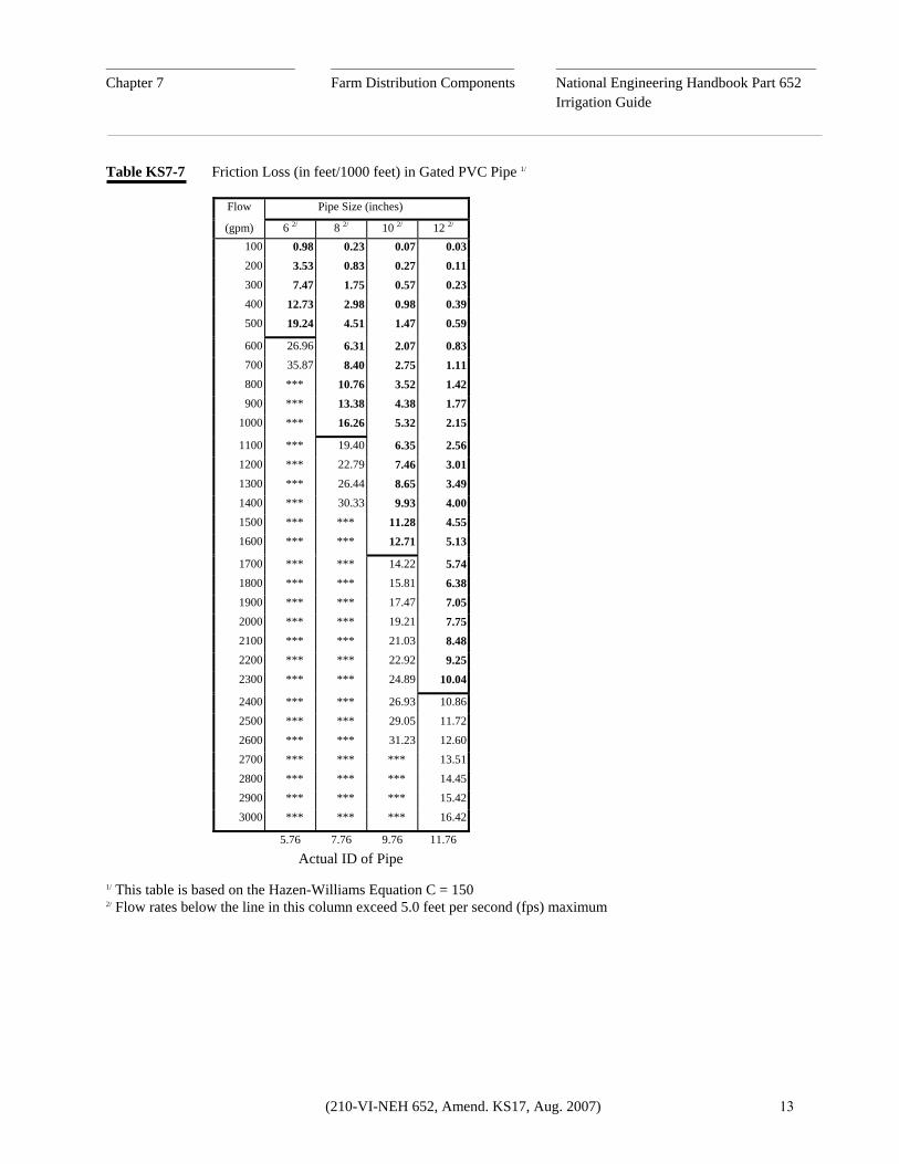
Chapter 7 Farm Distribution Components National Engineering Handbook Part 652 Irrigation Guide Table KS7-7 Friction Loss (in feet/1000 feet) in Gated PVC Pipe 1/
Flow Pipe Size (inches) (gpm) 6 2/ 8 2/ 10 2/ 12 2/ 100 0.98 0.23 0.07 0.03 200 3.53 0.83 0.27 0.11 300 7.47 1.75 0.57 0.23 400 12.73 2.98 0.98 0.39 500 19.24 4.51 1.47 0.59 600 26.96 6.31 2.07 0.83 700 35.87 8.40 2.75 1.11 800 *** 10.76 3.52 1.42 900 *** 13.38 4.38 1.77 1000 *** 16.26 5.32 2.15 1100 *** 19.40 6.35 2.56 1200 *** 22.79 7.46 3.01 1300 *** 26.44 8.65 3.49 1400 *** 30.33 9.93 4.00 1500 *** *** 11.28 4.55 1600 *** *** 12.71 5.13 1700 *** *** 14.22 5.74 1800 *** *** 15.81 6.38 1900 *** *** 17.47 7.05 2000 *** *** 19.21 7.75 2100 *** *** 21.03 8.48 2200 *** *** 22.92 9.25 2300 *** *** 24.89 10.04 2400 *** *** 26.93 10.86 2500 *** *** 29.05 11.72 2600 *** *** 31.23 12.60 2700 *** *** *** 13.51 2800 *** *** *** 14.45 2900 *** *** *** 15.42 3000 *** *** *** 16.42 5.76 7.76 9.76 11.76
Actual ID of Pipe
1/ This table is based on the Hazen-Williams Equation C = 150 2/ Flow rates below the line in this column exceed 5.0 feet per second (fps) maximum
(210-VI-NEH 652, Amend. KS17, Aug. 2007) 13
________________________________ _______________________________ ____________________________________________
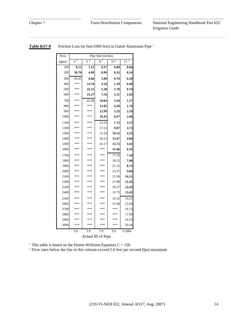
Chapter 7 Farm Distribution Components National Engineering Handbook Part 652 Irrigation Guide Table KS7-8 Friction Loss (in feet/1000 feet) in Gated Aluminum Pipe 1/
Flow Pipe Size (inches)
(gpm) 4 2/ 6 2/ 8 2/ 10 2/ 12 2/
100 8.51 1.13 0.27 0.09 0.04
200 30.70 4.09 0.99 0.33 0.14
300 65.05 8.66 2.09 0.70 0.29
400 *** 14.76 3.56 1.19 0.49
500 *** 22.31 5.38 1.79 0.74
600 *** 31.27 7.54 2.51 1.03
700 *** 41.60 10.04 3.34 1.37
800 *** *** 12.85 4.28 1.76
900 *** *** 15.99 5.33 2.19
1000 *** *** 19.43 6.47 2.66
1100 *** *** 23.18 7.72 3.17
1200 *** *** 27.23 9.07 3.73
1300 *** *** 31.58 10.52 4.32
1400 *** *** 36.23 12.07 4.96
1500 *** *** 41.17 13.72 5.63
1600 *** *** *** 15.46 6.35
1700 *** *** *** 17.29 7.10
1800 *** *** *** 19.22 7.90
1900 *** *** *** 21.25 8.73
2000 *** *** *** 23.37 9.60
2100 *** *** *** 25.58 10.51
2200 *** *** *** 27.88 11.45
2300 *** *** *** 30.27 12.43
2400 *** *** *** 32.75 13.45
2500 *** *** *** 35.32 14.51
2600 *** *** *** 37.98 15.60
2700 *** *** *** *** 16.73
2800 *** *** *** *** 17.90
2900 *** *** *** *** 19.10
3000 *** *** *** *** 20.34
3.9 5.9 7.9 9.9 11.884
Actual ID of Pipe
1/ This table is based on the Hazen-Williams Equation C = 150 2/ Flow rates below the line in this column exceed 5.0 feet per second (fps) maximum
(210-VI-NEH 652, Amend. KS17, Aug. 2007) 14

________________________________ _______________________________ ____________________________________________
Chapter 7 Farm Distribution Components National Engineering Handbook Part 652 Irrigation Guide Table KS7-9 Head Loss (in feet) Through Alfalfa Valves and Portable Hydrants
Valve and Riser Portable Hydrant Flow Valve Size (inches) Outlet Size (inches) (gpm) 8 10 12 14 6 8 10 12 400 0.3 0.1 0.1 0.0 0.3 0.1 0.0 0.0 500 0.4 0.2 0.1 0.0 0.5 0.2 0.1 0.0 600 0.6 0.3 0.1 0.1 0.7 0.2 0.1 0.0 700 0.9 0.4 0.2 0.1 1.0 0.3 0.1 0.1 800 1.1 0.5 0.2 0.1 1.3 0.4 0.2 0.1 900 1.4 0.6 0.3 0.2 1.6 0.5 0.2 0.1 1000 1.8 0.7 0.3 0.2 2.0 0.6 0.3 0.1 1100 2.1 0.9 0.4 0.2 2.4 0.8 0.3 0.2 1200 2.5 1.0 0.5 0.3 2.9 0.9 0.4 0.2 1300 3.0 1.2 0.6 0.3 3.4 1.1 0.4 0.2 1400 3.4 1.4 0.7 0.4 3.9 1.2 0.5 0.2 1500 3.9 1.6 0.8 0.4 4.5 1.4 0.6 0.3 1600 4.5 1.8 0.9 0.5 5.1 1.6 0.7 0.3 1700 5.1 2.1 1.0 0.5 5.8 1.8 0.7 0.4 1800 5.7 2.3 1.1 0.6 6.5 2.1 0.8 0.4 1900 6.3 2.6 1.3 0.7 7.2 2.3 0.9 0.5 2000 7.0 2.9 1.4 0.7 8.0 2.5 1.0 0.5 2100 7.7 3.2 1.5 0.8 8.8 2.8 1.1 0.6 2200 8.5 3.5 1.7 0.9 9.7 3.1 1.3 0.6 2300 9.3 3.8 1.8 1.0 10.6 3.4 1.4 0.7 2400 10.1 4.1 2.0 1.1 11.5 3.6 1.5 0.7 2500 11.0 4.5 2.2 1.2 12.5 4.0 1.6 0.8 2600 11.9 4.9 2.3 1.3 13.5 4.3 1.8 0.8 2700 12.8 5.2 2.5 1.4 14.6 4.6 1.9 0.9 2800 13.8 5.6 2.7 1.5 15.7 5.0 2.0 1.0 2900 14.8 6.0 2.9 1.6 16.8 5.3 2.2 1.1 3000 15.8 6.5 3.1 1.7 18.0 5.7 2.3 1.1
(210-VI-NEH 652, Amend. KS17, Aug. 2007) 15

________________________________ _______________________________ ____________________________________________
Chapter 7 Farm Distribution Components National Engineering Handbook Part 652 Irrigation Guide (3) Equations used to develop pipe friction loss tables Hazen-Williams Equation: hf = (1000) (3.552) (Q) 1/0.54
(C)(d 2.63) Manning's Equation: hf = (1000) (3.631) (Q) (n) 2 ( d)8/3 Where: hf = Friction loss (feet/1000 feet)
Q = Flow rate (gpm)
d = Inside pipe diameter (inches)
C = Hazen-Williams roughness coefficient
n = Manning's roughness coefficient (4) Equations used to develop head loss table For alfalfa valves and risers:
h = 2.77V2 2g For portable hydrants:
h = V2
2g Where: h = Head loss (feet) V = Flow velocity (feet/second) g = 32.2 (feet/sec.2) (d) Design summary for Conservation Practice 430EE, Irrigation Water Conveyance, Low-Pressure, Underground, Plastic Pipeline This summary covers the major criteria for this conservation practice. Refer to the standard and specifications in Section IV of the eFOTG for further details.
(1) Velocity
Flow Rate at Which a Velocity of 5 feet/second Occurs
Nominal Pipe Diameter (Inches) Flow Rate (gpm) 6 441 8 783 10 1224 12 1763 14 2399 15 2754 (2) Stands A pump stand or "dogleg" shall be located at the outlet of the pump discharge pipe. For a closed system, the minimum diameter of a stand or "dogleg" is the pipe diameter. (3) Check valves Install check valves between the pump discharge and the stand. (4) Pressure relief valves Install a pressure relief valve on the pump stand or level portion of the "dogleg."
Capacity of Various Pressure Relief Valves (in gpm) at 32.5 psi and Set to Open at 22 psi 1/
Valve Size Waterman Fresno (inches) AA-96C AA-9 AA-6 PR900 PR600 3 675 --- 60 630 165 4 1030 --- 120 1045 --- 6 --- 1580 --- 1550 --- 1/ From manufacturer's test data - Refer to
manufacturer's literature for pressure relief valve capacity for pipelines with working pressures greater than 22 psi.
(210-VI-NEH 652, Amend. KS17, Aug. 2007) 16
________________________________ _______________________________ ____________________________________________
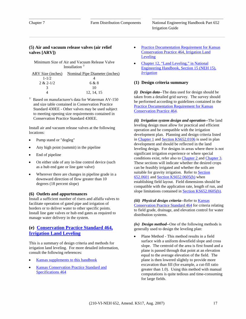
Chapter 7 Farm Distribution Components National Engineering Handbook Part 652 Irrigation Guide (5) Air and vacuum release valves (air relief valves [ARV])
Minimum Size of Air and Vacuum Release Valve Installation 1/
ARV Size (inches) Nominal Pipe Diameter (inches) 1-1/2 4 2 & 2-1/2 6 & 8 3 10 4 12, 14, 15 1/ Based on manufacturer's data for Waterman AV-150
and size table contained in Conservation Practice Standard 430EE - Other valves may be used subject to meeting opening size requirements contained in Conservation Practice Standard 430EE.
Install air and vacuum release valves at the following locations:
• Pump stand or "dogleg"
• Any high point (summit) in the pipeline
• End of pipeline
• On either side of any in-line control device (such as a hub end gate or line gate valve)
• Wherever there are changes in pipeline grade in a downward direction of flow greater than 10 degrees (18 percent slope)
(6) Outlets and appurtenances Install a sufficient number of risers and alfalfa valves to facilitate operation of gated pipe and irrigation of borders or to deliver water to other specific points. Install line gate valves or hub end gates as required to manage water delivery in the system. (e) Conservation Practice Standard 464, Irrigation Land Leveling This is a summary of design criteria and methods for irrigation land leveling. For more detailed information, consult the following references:
• Kansas supplements to this handbook
• Kansas Conservation Practice Standard and Specifications 464
• Practice Documentation Requirement for Kansas Conservation Practice 464, Irrigation Land Leveling
• Chapter 12, “Land Leveling,” in National Engineering Handbook, Section 15 (NEH 15), Irrigation
(1) Design criteria summary (i) Design data--The data used for design should be taken from a detailed grid survey. The survey should be performed according to guidelines contained in the Practice Documentation Requirement for Kansas Conservation Practice 464. (ii) Irrigation system design and operation--The land leveling design must allow for practical and efficient operation and be compatible with the irrigation development plan. Planning and design criteria listed in Chapter 1 and Section KS652.0106 is used in plan development and should be reflected in the land leveling design. For designs in areas where there is not significant irrigation experience or where special conditions exist, refer also to Chapter 2 and Chapter 3. These sections will indicate whether the desired crops can be feasibly irrigated and whether the soils are suitable for gravity irrigation. Refer to Section 652.0601 and Section KS652.0605(b) when establishing field layout. Field dimensions should be compatible with the application rate, length of run, and slope limitations contained in Section KS652.0605(b). (iii) Physical design criteria--Refer to Kansas Conservation Practice Standard 464 for criteria relating to field grade, drainage, and elevation control for water distribution systems. (iv) Design method--One of the following methods is generally used to design the leveling plan:
• Plane Method - This method results in a field surface with a uniform downfield slope and cross slope. The centroid of the area is first found and a plane is passed through that point at an elevation equal to the average elevation of the field. The plane is then lowered slightly to provide more excavation than fill (for example, a cut-fill ratio greater than 1.0). Using this method with manual computations is quite tedious and time-consuming for large fields.
(210-VI-NEH 652, Amend. KS17, Aug. 2007) 17

________________________________ _______________________________ ____________________________________________
Chapter 7 Farm Distribution Components National Engineering Handbook Part 652 Irrigation Guide • Profile Method - Using this method, the designer
works with profiles of grid lines rather than individual grid elevations. This is a trial-and-error method of adjusting grades on plotted profiles until all design criteria are satisfied. The profile grades are then transferred to the grid map, design elevations computed, and the resulting leveling map checked for adherence to forward slope and cross slope criteria. Also, earthwork computations are made to determine if the cut-fill ratio is satisfactory.
• Plan-Inspection Method - This is a trial-and-error method that relies heavily upon the knowledge, experience, and judgment of the designer. When using this method, contours are generally plotted on a copy of the grid map. Contour interval will depend upon the topography and desired field slopes. On nearly level fields, a contour interval of 0.5 foot may be desirable. For design slopes of 0.5-1.0 percent, contour intervals of 1.0 foot are generally satisfactory. Using the contours as indicators, areas of relatively uniform slope are assigned trial elevations or grades. The contours may also indicate areas where variable grade may be desirable. Where extreme elevation differences occur, contours may be used to guide placement of bench areas. The trial elevations assigned to the grid points are then checked for conformance to grade criteria. Earthwork computations are performed to determine if the cut-fill ratio is satisfactory. Also, extreme values of cut and fill should be inspected to determine if they are feasible (as should haul distances).
• Contour Adjustment Method - This method consists of trial-and-error adjustment of contour lines drawn on the grid map. Design elevations at the grid points are determined by interpolating between the design or adjusted contours. Like the other methods, cuts and fills are determined by comparing the design elevations to the original elevations, grades are checked, and earthwork computations are performed. This method is best adapted to fields where uniform cross slope is feasible and for contour furrow irrigation systems.
(v) Earthwork calculations--A number of methods may be used to estimate earthwork volumes during the trial-and-error phase of the design. All final design quantities, however, are to be computed using the four-point method. The following explanation of the four-point method was taken from Chapter 12, “Land Leveling,” in NEH 15, Irrigation. (2) Design documentation and plans Figure KS7-5 illustrates the format typically used to develop design documentation and plans. Refer to the Practice Documentation Requirement for Kansas Conservation Practice 464 for complete examples of land leveling plans. Where: V = Volume (in cubic feet) L = Perpendicular distance between end
planes (in feet) A1 = Area of one end plane (in square feet) A2 = Area of other end plane (in square feet) Am= Area in middle section parallel to end
planes (in square feet)
The use of this formula is laborious, and approximate methods are commonly used.
The four-point method--The four-point method is based on the following formula:
Vc = L2 ( Hc2 )
108 (Hc + Hf) and Vf = L2 ( Hf
2 ) 108 (Hc + Hf) Where: Vc = Volume of cut (in cubic yard)s Vf = Volume of fill (in cubic yards) L = Grid spacing (in feet) Hc = Sum of cuts on four corners of a grid
square (in feet) Hf = Sum of fills on four corners of a grid
square (in feet)
(210-VI-NEH 652, Amend. KS17, Aug. 2007) 18

________________________________ _______________________________ ____________________________________________
Chapter 7 Farm Distribution Components National Engineering Handbook Part 652 Irrigation Guide Figure KS7-5 Format for Listing Elevations, Cuts, and Fills on Land Leveling Grid Maps
Normal Field Layout (100-foot by 100-foot grid)
98 2 98 5 97 7 97 1 - Original elevation 98 2 98 0 97 8 97 6 - Planned or design elevation 0 0 -0 5 +0 1 +0 5 - Cut (-) or fill (+) or use C = cut and F = fill
98 1 98 6 97 9 96 9 98 2 98 0 97 8 97 6 +0 1 -0 6 -0 1 +0 7
Optional: Record as-built (final checkout) elevations above original elevations.
Horizontal Bench Line
To denote elevations on either side of a bench boundary shown horizontally on the leveling map:
+0.6 +0.1 +0.7 +1.1 - Cut (-) or fill (+) 98.8 98.6 98.4 98.2 - Planned or design elevation 98.2 98.5 97.7 97.1 - Original elevation 97.8 97.6 97.4 97.2 - Planned or design elevation -0.4 -0.9 -0.3 +0.1 - Cut (-) or fill (+) Optional: Record as-built (final checkout) elevations vertically along the side of the planned and original elevations.
Vertical Bench Line
To denote elevations on either side of a bench boundary shown vertically on the leveling map: 98.5 97 7 - Original elevation 98.0 98.0 97.0 - Planned or design elevation -0.5 +0.3 -0.7 - Cut (-) or fill (+) 98.6 97 9 97.8 97.8 96.8 -0.8 -0.1 -1.1 98.2 96 5 97.6 97.6 96.6 -0.6 +1.1 +0.1
Optional: Record as-built (final checkout) elevations above original elevations.
Color Coding System
The following color coding system has been used to develop land leveling grid maps:
Original elevation - black ink Cut - red Planned or design elevation - pencil Fill - blue As-built or final checkout elevation - green
(210-VI-NEH 652, Amend. KS17, Aug. 2007) 19

________________________________ _______________________________ ____________________________________________
Chapter 7 Farm Distribution Components National Engineering Handbook Part 652 Irrigation Guide Using the formula, the volume of cut and fill in each grid square can be ascertained and the totals for the field obtained. Table KS7-10 provides a rapid method for determining the excavation and fill in a 100-foot grid square. Examine the following grid: The sum of the cuts is 0.4, and the sum of the fills is 0.3. Since the square is 100 feet to a side, the volume of earthwork as given by Table KS7-10 is as follows: Excavation 21 cubic yards Fill 12 cubic yards The following methods have been found satisfactory for computing the volumes in other than square grids. For grids with four corners: 35 + 55 Area grid = 2 x 100 = 4,500 square feet Area in 100 x 100 grid = 10,000 square feet From Table KS7-10 for a 100 x 100 grid: Cut = 59 cubic yards Fill = 4 cubic yards
For the reduced grid:
Excavation = 59 x 4 500 (or .45) = 27 cubic yards 10,000 Fill = 4 x .45 = 2 cubic yards
Correct use of the four-point method requires that the cut or fill be known at the outside edges of the field. In practice, however, stakes are seldom placed in the fence lines, and usually it is satisfactory to assume that the cut in the fence line is identical to that of the nearest stake. Where abnormal conditions exist, plus stakes should be used. For the grid shown below, the following calculation was made:
Area in grid = 30 x 100 = 3,000 square feet
From Table KS7-10: C = 9 cubic yards F = 9 cubic yards Corrected Volume = 3000 (or .3) x 9 = 3 cubic yards 10,000 C = 3 F = 3
(210-VI-NEH 652, Amend. KS17, Aug. 2007) 20

________________________________ _______________________________ ____________________________________________
Chapter 7 Farm Distribution Components National Engineering Handbook Part 652 Irrigation Guide For a triangular area, the sum of the three corners can be taken and the values in the table reduced to two-thirds. Thus, Sum of cuts = 0.4 Sum of fills = 0.2 From Table KS7-10, C = 25 and F = 6 Excavation = 2/3 x 25 = 17 cubic yards Fill = 2/3 x 6 = 4 cubic yards When triangular areas not 100 feet on each side are encountered, the volumes may be determined by further
reducing the tabular values in proportion to the product of the length of the sides
Sum of cuts = 0.4 Sum of fills = 0.2
Excavation = 50 x 75 x (or .375) x 25 = 6 cubic yards 100 x 100 Fill = .25 x 6 = 2 cubic yards The four-point method is rapid and gives an accuracy comparable to the accuracy of the original survey.
(210-VI-NEH 652, Amend. KS17, Aug. 2007) 21

__________________________________________ ____________________________________________
C
_____________________________________________________
hapter 7 Farm Distribution Components National Engineering Handbook Part 652 Irrigation Guide
(210-VI-NEH 652, Amend. KS17, Aug. 2007)
Table KS7-10 Earthwork Quantities in Cubic Yards with 100-Foot Land Leveling Grid
SUM OF CUTS ON FOUR CORNERS
0.0 0.1 0.2 0.3 0.4 0.5 0.6 0.7 0.8 0.9 1.0 1.1 1.2 1.3 1.4 1.5 1.6 1.7 1.8 1.9 2.0 2.1 2.2 2.3 2.4 2.5 2.6 2.7 2.8 2.9 3.0 3.1 3.2 3.3 3.4 3.5 3.6 3.7 3.8 3.9 4.0 4.1 4.2 4.3 4.4 4.5 4.6 4.7 4.8 4.9 5.0 5.1 5.2 5.3 5.4 5.5 5.6 5.7 5.8 5.9 6.0
0.0 CUT FILL
0 0
9 0
19 0
29 0
37 0
46 0
56 0
65 0
74 0
83 0
93 0
102 0
111 0
120 0
130 0
139 0
148 0
157 0
167 0
176 0
185 0
194 0
204 0
213 0
222 0
232 0
241 0
250 0
259 0
269 0
279 0
287 0
296 0
306 0
315 0
324 0
333 0
343 0
352 0
361 0
370 0
380 0
389 0
398 0
407 0
417 0
426 0
435 0
444 0
454 0
463 0
472 0
482 0
491 0
500 0
509 0
519 0
528 0
537 0
546 0
556 0 0.0
0.1 CUT FILL
0 9
5 5
12 3
21 2
30 2
39 2
48 1
57 1
66 1
75 1
84 1
93 1
103 1
112 1
121 1
130 1
139 1
149 1
158 1
167 1
176 0
186 0
195 0
204 0
213 0
223 0
232 0
241 0
250 0
260 0
269 0
279 0
287 0
297 0
306 0
315 0
324 0
334 0
343 0
352 0
361 0
371 0
380 0
389 0
398 0
408 0
417 0
426 0
435 0
445 0
454 0
463 0
472 0
482 0
491 0
500 0
509 0
519 0
528 0
537 0
546 0 0.1
0.2 CUT FILL
0 19
3 12
9 9
17 7
25 6
33 5
42 5
50 4
59 4
68 3
77 3
86 3
95 3
104 3
113 2
123 2
132 2
141 2
150 2
159 2
168 2
179 2
187 2
196 2
205 1
214 1
224 1
233 1
242 1
251 1
260 1
270 1
279 1
288 1
297 1
307 1
316 1
325 1
334 1
343 1
353 1
362 1
370 1
380 1
390 1
399 1
408 1
417 1
427 1
436 1
445 1
454 1
464 1
473 1
482 1
491 1
501 1
510 1
519 1
528 1
538 1 0.2
0.3 CUT FILL
0 28
2 21
7 17
14 14
21 12
29 10
37 9
45 8
54 8
63 7
71 6
80 6
89 6
98 5
107 5
116 5
125 4
134 4
143 4
152 4
161 4
170 4
179 3
188 3
198 3
207 3
216 3
225 3
234 3
243 3
253 3
262 3
271 2
280 2
289 2
299 2
308 2
317 2
326 2
335 2
345 2
354 2
363 2
372 2
381 2
391 2
400 2
409 2
418 2
428 2
437 2
446 2
455 2
464 2
474 2
483 1
492 1
501 1
511 1
520 1
529 1 0.3
0.4 CUT FILL
0 37
2 30
6 25
12 21
19 19
26 17
33 15
41 14
49 12
58 11
66 11
75 10
83 9
92 9
101 8
110 8
119 7
127 7
136 7
145 6
154 6
163 6
172 6
181 6
191 5
200 5
209 5
213 5
227 5
236 5
245 4
254 4
263 4
273 4
282 4
291 4
300 4
309 4
318 4
328 3
337 3
346 3
355 3
364 3
373 3
383 3
392 3
401 3
410 3
419 3
429 3
438 3
447 3
456 3
466 3
475 3
484 3
493 2
502 2
512 2
521 2 0.4
0.5 CUT FILL
0 46
2 39
5 33
10 29
17 26
23 23
30 21
38 19
46 18
54 17
52 15
70 15
78 14
87 13
96 12
104 12
113 11
122 11
130 10
139 10
148 9
157 9
166 9
175 8
184 8
193 8
202 8
211 7
220 7
229 7
238 7
247 6
256 6
265 6
274 6
284 6
293 6
302 6
311 5
320 5
329 5
338 5
348 5
357 5
366 5
375 5
384 5
393 5
403 4
412 4
421 4
430 4
439 4
448 4
458 4
467 4
476 4
485 4
494 4
504 4
513 4 0.5
0.6 CUT FILL
0 56
1 48
5 42
9 37
15 33
21 30
28 28
35 26
42 24
50 22
58 21
56 20
74 19
82 18
91 17
99 16
108 15
115 15
125 14
134 13
142 13
151 12
160 12
169 12
178 11
187 11
196 10
205 10
214 10
223 10
232 9
241 9
250 9
259 9
268 8
277 8
286 8
295 8
304 8
313 7
322 7
331 7
341 7
349 7
359 7
368 7
377 6
386 7
395 6
404 6
413 6
423 6
432 6
441 6
450 6
459 6
468 5
478 5
487 5
496 5
505 5 0.6
0.7 CUT FILL
0 65
1 57
4 50
8 45
14 41
19 38
25 35
32 32
40 30
47 28
55 27
62 25
70 24
78 23
86 22
95 21
103 20
112 19
120 18
129 18
137 17
146 16
155 16
163 15
172 15
181 14
190 14
199 13
208 13
216 13
225 12
234 12
243 12
252 11
261 11
270 11
279 11
288 10
297 10
306 10
313 10
324 10
334 9
343 9
352 9
361 9
369 9
378 8
388 8
397 8
406 8
415 8
424 8
433 8
443 7
452 7
461 7
470 7
479 7
488 7
498 7 0.7
0.8 CUT FILL
0 74
1 66
4 59
8 54
12 49
18 46
24 42
30 40
37 37
44 35
51 33
59 31
67 30
75 28
83 27
91 26
99 25
107 24
115 23
124 22
132 21
141 20
149 20
158 19
167 19
175 18
184 17
193 17
202 17
211 16
219 16
223 15
237 15
246 15
255 14
264 14
273 14
282 13
291 13
300 13
309 12
318 12
327 12
335 12
345 11
354 11
363 11
372 11
381 11
390 10
399 10
408 10
417 10
426 10
436 10
445 9
454 9
463 9
472 9
481 9
490 9 0.8
0.9 CUT FILL
0 83
1 75
3 68
7 63
11 58
17 54
22 50
28 47
35 44
42 42
19 40
56 38
64 36
71 34
79 33
87 31
95 30
103 29
111 28
119 27
128 26
136 25
145 24
153 23
162 23
170 22
179 21
188 21
196 20
205 20
214 19
223 19
231 18
240 18
249 17
258 17
267 17
276 16
285 16
293 16
302 15
311 15
320 15
329 14
338 14
347 14
357 14
365 13
374 13
383 13
392 13
401 13
410 12
419 12
429 12
438 12
447 12
456 11
465 11
474 11
483 11 0.9
1.0 CUT FILL
0 93
1 84
3 77
7 71
11 66
15 62
21 58
27 55
33 51
40 49
15 46
53 44
61 42
68 40
76 39
83 37
91 36
99 34
107 33
115 32
124 31
132 30
140 29
148 28
157 27
165 27
174 26
183 25
191 24
200 24
208 23
217 23
225 22
235 22
243 21
252 21
261 20
270 20
279 20
288 19
296 19
305 18
314 18
323 18
332 17
341 17
350 17
359 16
368 16
377 16
386 15
395 15
404 15
413 15
422 15
431 14
440 14
449 14
458 14
467 13
476 13 1.0
1.1 CUT FILL
0 102
1 93
3 86
6 80
10 75
15 70
20 66
25 62
31 59
38 56
44 53
51 51
58 49
65 47
73 45
80 43
88 42
96 40
104 39
111 37
120 36
123 35
136 34
144 33
152 32
161 31
169 30
179 30
186 29
195 28
203 27
212 27
221 26
229 26
238 25
247 24
255 24
264 23
273 23
284 22
291 22
299 22
308 21
317 21
326 20
335 20
344 20
353 19
362 19
371 19
379 18
388 18
397 18
406 18
415 17
424 17
433 17
442 17
451 16
460 16
469 16 1.1
1.2 CUT FILL
0 111
1 103
3 95
6 89
9 83
14 78
19 74
24 70
30 67
36 64
42 61
49 58
56 56
63 53
70 51
77 49
85 48
92 46
100 44
107 43
116 42
124 40
132 39
140 38
148 37
156 36
165 35
173 34
182 33
190 33
199 32
207 31
216 30
224 30
233 29
241 28
250 28
259 27
267 27
276 26
285 26
294 25
303 25
311 24
320 24
329 23
338 23
347 23
356 22
364 22
373 22
382 21
391 21
400 21
409 21
418 20
427 20
436 19
445 19
454 19
463 19 1.2
1.3 CUT FILL
0 120
1 112
3 104
5 98
9 92
13 93
18 82
23 78
28 75
34 71
40 68
47 65
53 63
60 60
67 58
74 56
82 54
89 52
97 51
104 49
112 47
120 46
128 45
136 44
144 42
152 41
161 40
169 39
177 38
185 37
194 36
202 36
211 35
219 34
229 33
236 33
245 32
254 31
262 31
271 30
280 30
288 29
298 29
306 28
314 28
323 27
332 27
341 26
350 26
359 25
367 25
376 25
385 24
394 24
403 23
412 23
421 23
430 22
439 22
448 22
457 21 1.3
1.4 CUT FILL
0 130
1 121
2 113
5 107
8 101
12 96
17 91
22 86
27 83
33 79
39 76
45 73
51 70
58 67
65 65
72 63
79 61
86 59
94 57
101 55
109 53
117 52
125 50
132 49
140 48
148 47
157 45
165 44
173 43
181 42
189 41
198 40
206 40
215 39
223 38
232 37
240 36
249 36
257 35
266 34
274 34
283 33
292 32
300 32
309 31
318 31
326 30
335 30
344 29
353 29
362 28
371 28
379 28
388 27
397 27
406 26
415 26
424 26
433 25
442 25
450 25 1.4
1.5 CUT FILL
0 139
1 130
2 123
5 116
8 110
12 104
16 99
21 95
26 91
31 87
37 83
43 80
49 77
56 74
63 72
69 69
77 67
84 65
91 63
98 61
106 60
113 58
121 56
129 55
137 53
145 52
153 51
161 50
169 48
177 47
185 46
194 45
202 44
210 43
219 43
227 42
235 41
244 40
252 39
261 39
269 38
278 37
287 37
293 36
304 35
313 35
321 34
330 34
339 33
347 33
356 32
365 32
374 31
382 31
391 30
400 30
409 29
418 29
427 29
436 28
444 28 1.5
1.6 CUT FILL
0 148
1 139
2 132
4 125
7 119
11 113
15 108
20 103
25 99
30 95
36 91
42 88
48 85
54 82
61 79
67 77
74 74
81 72
88 70
96 68
103 66
110 64
118 62
126 61
133 59
141 58
149 57
157 55
165 54
173 53
181 52
189 50
198 49
206 48
214 47
223 47
231 46
239 45
248 44
256 43
265 42
273 42
282 41
290 40
299 40
307 39
316 38
325 38
333 37
342 37
351 36
359 35
368 35
377 34
386 34
394 33
403 33
412 33
421 32
430 32
439 31 1.6
1.7 CUT FILL
0 157
1 149
2 141
4 134
7 127
11 122
15 116
19 112
24 107
29 103
34 99
40 96
46 92
52 89
59 86
65 84
72 81
79 79
86 77
93 74
100 72
108 70
115 69
123 67
130 65
138 64
146 62
153 61
161 60
169 60
177 57
185 56
194 55
202 54
210 53
218 52
226 51
235 50
243 49
251 48
260 47
268 46
277 45
285 45
294 44
302 43
311 43
320 42
328 41
337 41
346 40
354 39
363 39
372 38
380 38
389 37
398 37
407 36
415 36
424 35
433 35 1.7
1.8 CUT FILL
0 167
1 158
2 150
4 143
7 136
10 130
14 125
18 120
23 115
28 111
33 107
39 104
44 100
51 97
57 94
63 91
70 88
77 86
83 83
90 81
98 79
105 77
112 75
120 73
127 71
135 70
142 68
150 67
158 65
166 64
174 63
182 61
190 60
198 59
206 58
214 57
222 56
231 55
239 54
247 53
255 52
264 51
273 50
281 49
289 48
298 48
306 47
315 46
323 46
332 45
340 44
349 44
358 43
366 42
375 42
384 41
392 41
401 40
410 40
419 39
427 39 1.8
1.9 CUT FILL
0 176
1 167
2 159
4 152
6 145
10 139
13 134
18 129
22 124
27 119
32 115
37 111
43 108
49 105
55 101
61 98
68 96
74 93
81 90
83 88
95 86
102 84
109 82
117 80
124 78
132 76
139 74
147 73
155 71
162 70
170 68
178 67
186 66
194 64
202 63
210 62
218 61
226 60
235 59
243 58
251 57
259 56
268 55
276 54
285 53
293 52
301 51
310 51
318 50
327 49
336 48
344 48
353 47
361 46
370 46
378 45
387 45
396 44
404 43
413 43
422 42 1.9
2.0 CUT FILL
0 185
0 176
2 168
4 161
6 154
9 148
13 142
17 137
21 132
25 128
31 124
36 120
42 116
47 112
53 109
60 106
66 103
72 100
79 98
86 95
93 93
100 90
107 88
114 86
121 84
129 82
136 81
144 79
151 77
159 76
167 74
175 73
182 71
190 70
198 69
206 67
214 66
222 65
231 64
239 63
247 62
255 61
264 60
271 59
280 58
288 57
296 56
305 55
314 55
322 54
331 53
339 52
348 51
356 51
365 50
373 49
382 49
391 48
399 48
408 47
417 46 2.0
2.1 CUT FILL
0 194
0 186
2 178
4 170
6 163
9 157
12 151
16 146
20 141
25 136
30 132
35 128
40 124
46 120
52 117
58 113
64 110
70 108
77 105
84 102
90 100
97 97
104 95
111 93
119 91
126 89
133 87
141 85
148 83
156 82
163 80
171 79
180 77
187 76
195 74
203 73
211 72
219 70
227 69
235 68
243 67
251 66
260 65
267 64
276 63
284 62
292 61
301 60
309 59
318 58
325 58
334 57
343 56
351 55
360 54
369 54
377 53
386 52
394 52
403 51
412 50 2.1
2.2 CUT FILL
0 204
0 195
2 187
3 179
6 172
9 166
12 160
16 155
20 149
24 145
29 140
34 136
39 132
45 128
50 125
56 121
62 118
69 115
75 112
82 109
88 107
95 104
102 102
109 100
116 97
123 95
130 93
138 92
145 90
153 88
160 86
168 85
176 83
183 82
191 80
199 79
207 77
215 76
223 75
231 74
239 72
247 71
256 70
263 69
272 68
280 67
288 66
295 65
305 64
313 63
322 62
330 61
338 61
347 60
355 59
364 58
372 58
381 57
389 56
398 55
407 55 2.2
2.3 CUT FILL
0 213
0 204
2 196
3 188
6 181
8 175
12 169
15 163
19 158
23 153
28 148
33 144
38 140
44 136
49 132
55 129
61 126
67 123
73 120
80 117
86 114
93 111
100 109
107 107
114 104
121 102
128 100
135 98
142 96
150 94
157 92
165 91
172 89
180 87
188 86
196 84
203 83
211 82
219 80
227 79
235 78
243 77
252 75
259 74
268 73
276 72
284 71
292 70
301 69
309 68
317 67
325 66
334 65
342 64
351 64
359 63
368 62
376 61
385 61
393 60
402 59 2.3
2.4 CUT FILL
0 222
0 213
1 205
3 198
5 191
8 184
11 178
15 172
19 167
23 162
27 157
32 152
37 148
42 144
48 140
53 137
59 133
65 130
71 127
78 124
84 121
91 119
97 116
104 114
111 111
118 109
125 107
132 105
140 103
147 101
154 99
162 97
169 95
177 94
185 92
192 90
200 89
208 87
216 86
224 85
232 83
239 82
248 81
256 80
264 78
272 77
280 76
288 75
296 74
305 73
313 72
321 71
329 70
338 69
346 68
355 68
363 67
371 66
380 65
388 64
397 64 2.4
2.5 CUT FILL
0 232
0 223
1 214
3 207
5 200
8 193
11 187
14 181
18 175
22 170
27 165
31 161
36 156
41 152
47 148
52 145
58 141
64 138
70 135
76 132
82 129
89 126
95 123
102 121
109 118
116 116
123 114
130 111
137 109
144 107
152 105
159 103
166 102
174 100
181 98
189 96
197 95
204 93
212 92
220 90
228 89
236 88
244 86
252 85
260 84
268 83
275 82
284 80
292 79
300 78
309 77
317 76
325 75
333 74
342 73
350 72
358 71
367 71
375 70
384 69
392 68 2.5
2.6 CUT FILL
0 241
0 232
1 224
3 216
5 209
8 202
10 196
14 190
17 184
21 179
25 174
30 169
35 165
40 161
45 157
51 153
57 149
62 146
68 142
74 139
81 136
87 133
93 130
100 128
107 125
114 123
120 120
127 118
135 116
142 114
149 112
156 110
163 108
171 106
178 104
186 103
194 101
201 99
209 98
217 96
225 95
232 93
241 92
247 91
256 89
264 88
272 87
280 86
288 85
296 84
305 82
313 81
321 80
329 79
338 78
346 77
354 76
362 75
371 75
379 74
388 73 2.6
2.7 CUT FILL
0 250
0 241
1 233
3 225
5 218
7 211
10 205
13 199
17 193
21 188
25 183
30 178
34 173
39 169
44 165
50 161
55 157
61 153
67 150
73 147
79 144
85 141
92 138
98 135
105 132
111 130
118 127
125 125
132 123
139 121
146 118
153 116
161 114
168 113
176 111
183 109
191 107
198 106
206 104
213 102
221 101
229 99
237 98
244 96
253 95
260 94
268 93
276 91
284 90
293 88
301 88
309 87
317 85
325 84
333 83
342 82
350 81
358 80
366 79
375 79
383 78 2.7
2.8 CUT FILL
0 259
0 250
1 242
3 234
5 227
7 220
10 214
13 208
17 202
20 196
24 191
29 186
33 182
38 177
43 173
48 169
54 165
60 161
65 158
71 155
77 151
83 148
90 145
96 142
103 140
109 137
116 135
123 132
130 130
137 127
144 125
151 123
158 121
165 119
173 117
180 115
188 113
195 112
203 110
210 108
218 107
226 105
233 104
241 102
249 101
257 99
264 98
273 97
281 96
289 94
297 93
305 92
313 91
321 90
329 89
337 88
346 86
354 85
362 84
371 83
379 83 2.8
2.9 CUT FILL
0 269
0 260
1 251
3 243
5 236
7 229
10 223
13 216
16 211
20 205
24 200
28 195
33 190
37 185
42 181
47 177
53 173
58 169
64 166
70 162
75 159
82 156
88 153
94 150
101 147
107 144
114 142
121 139
127 137
134 134
141 132
148 130
155 128
163 126
170 124
177 122
185 120
192 118
200 116
207 115
215 113
222 111
231 110
238 108
246 107
253 105
261 104
269 103
277 101
285 100
293 99
301 97
309 96
317 95
326 94
333 93
342 92
350 91
358 90
366 89
374 88 2.9
3.0 CUT FILL
0 278
0 269
1 260
3 253
4 245
7 238
9 232
12 225
16 219
19 214
23 208
27 203
32 199
36 194
41 189
46 185
52 181
57 177
63 174
68 170
74 167
80 163
86 160
92 157
99 154
105 152
112 149
118 146
125 144
132 141
139 139
146 137
153 134
160 132
167 130
175 128
182 126
189 124
197 123
204 121
212 119
219 117
227 116
234 114
242 113
250 111
257 110
266 108
273 107
281 106
289 104
297 103
305 102
313 100
321 99
329 98
338 97
346 96
354 95
362 94
370 93 3.0
0.0 0.1 0.2 0.3 0.4 0.5 0.6 0.7 0.8 0.9 1.0 1.1 1.2 1.3 1.4 1.5 1.6 1.7 1.8 1.9 2.0 2.1 2.2 2.3 2.4 2.5 2.6 2.7 2.8 2.9 3.0 3.1 3.2 3.3 3.4 3.5 3.6 3.7 3.8 3.9 4.0 4.1 4.2 4.3 4.4 4.5 4.6 4.7 4.8 4.9 5.0 5.1 5.2 5.3 5.4 5.5 5.6 5.7 5.8 5.9 6.0
SUM OF CUTS ON FOUR CORNERS
22


![Telecommunication Products - Trendtek jointing pits.pdf · [01] UG2006 - P6 Pit UG2007 - P7 Pit UG2008 - P8 Pit UG2900 - P9 Pit UG2001 - P1 Pit UG2002 - P2 Pit UG2003 - P3 Pit UG2004](https://img.pdfslide.us/doc/110x75/5a7969077f8b9ab9308d3433/telecommunication-products-jointing-pitspdf01-ug2006-p6-pit-ug2007-p7-pit.jpg)